How to Install Metal Lath - AMICO Building Products
How to Install Metal Lath - AMICO Building Products
How to Install Metal Lath - AMICO Building Products

You also want an ePaper? Increase the reach of your titles
YUMPU automatically turns print PDFs into web optimized ePapers that Google loves.
<strong>How</strong> <strong>to</strong> <strong>Install</strong> <strong>Metal</strong> <strong>Lath</strong><br />
These installation recommendations are intended <strong>to</strong> be instructional<br />
and accurate. This is first a guideline, providing a general<br />
overview and also equips the lather with specific installation<br />
details, based on ASTM C 1063-08 Standard Specification for<br />
<strong>Install</strong>ation of <strong>Metal</strong> <strong>Lath</strong>.<br />
Always consult your area building official before beginning any project<br />
<strong>to</strong> familiarize yourself with any local code requirements. This guide<br />
should not replace the designs and judgments of a qualified engineer<br />
and/or architect.<br />
<strong>Lath</strong> <strong>Install</strong>ation<br />
Begin at the right hand bot<strong>to</strong>m corner of the wall. If paper backing<br />
behind the lath is required, leave the paper overhanging at the <strong>to</strong>p and<br />
<strong>to</strong> the left of the sheet. Offset paper backing has the paper overlapping<br />
1-1/2” on one end and one side and corresponding retracted on<br />
the opposite end and side, the sheets should always be installed in a<br />
horizontal application perpendicular <strong>to</strong> the framing.<br />
Laps: Minimum of 1” at edges with ends nested paper <strong>to</strong> paper, metal<br />
<strong>to</strong> metal. Apply the second sheet <strong>to</strong> the left of the first sheet lapping<br />
paper over paper and lath over lath. Place the third sheet centered<br />
above the first two sheets. This process is similar <strong>to</strong> that of laying<br />
brick. This staggers the vertical butt joint seams and allows a more<br />
uniform dispersal of stress.<br />
Nailing Methods<br />
On horizontal applications all nails shall be driven flush with base.<br />
On vertical applications nails shall be bent over <strong>to</strong> engage at least 3<br />
strands over and through rib on rib lath and bridge ribs with staples.<br />
<strong>Lath</strong> Fasteners (per ASTM C-1063)<br />
Concrete/CMU: use (3/8” diameter shank, 3/4” minimum length).<br />
6 power or powder actuated fasteners, 4 in the corners and 2 in the<br />
middle of long edge.<br />
Wood framing: use 11 gauge 1-1/2” length, 7/16” head nails (roofing<br />
nails 4d 1-1/2” x1/4 head)<br />
Sheathing on wood framing: use 14 gauge, 1-1/2” leg, 3/4” crown<br />
staples<br />
<strong>Metal</strong> framing: use self drilling, self tapping #12 x 3/4” wafer head<br />
screws. Use of powder actuated or power actuated fasteners is acceptable,<br />
but may cause spalling when shot <strong>to</strong> the substrate; follow<br />
manufacturer’s instructions carefully.<br />
ICF: Consult specific ICF manufacturer.<br />
Fastener Spacing<br />
Spacing of nails, staples or screws is not more than 7” on center along<br />
the framing member (horizontal or vertical).<br />
Concrete: 6 power actuated fasteners, 4 in corners, 1 on each side of<br />
long edge in center.<br />
Span Limitations<br />
Every finish material is subject <strong>to</strong> span limitations, which is the<br />
maximum distance between frame members. When sheathing is not<br />
10 www.amico-lath.com | 800.366.2642<br />
required, 16” on center is the maximum spacing of framing <strong>to</strong> prevent<br />
undue sagging. Then minimum 2.5# self-furring lath is installed over<br />
sheathing or solid surface, the maximum spacing of supports may be<br />
24” on center.<br />
*Note: <strong>Lath</strong> shall be furred away from vertical supports or solid surfaces<br />
at least ¼”. Self-furring lath “dimples” “V-grooved” or “ribbed”<br />
lath meets these furring requirements. See chart “Support Spacing for<br />
<strong>Metal</strong> <strong>Lath</strong>” on page 3 (bot<strong>to</strong>m) of this catalog.<br />
Cut and Trim <strong>to</strong> Fit<br />
Standard sheet shears or metal cutting scissors are effectively used for<br />
notching and snipping. A conventional circular saw equipped with a metal<br />
cutting blade easily zips through steel lath <strong>to</strong> cut <strong>to</strong> desired lengths.<br />
Wire Tie (0.0475”, 18-gauge)<br />
<strong>Lath</strong> is <strong>to</strong> be wire tied at 9” on center at edges, ends and at laps between<br />
framing members. On plywood sheathing only, lath may be nailed or<br />
stapled in lieu of tying at the same center spacing noted above.<br />
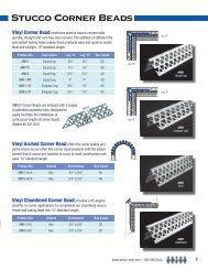
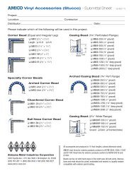
Accessories<br />
Corner beads shall be used <strong>to</strong> protect all external corners with a plumb<br />
and true edge. Casing beads shall be used <strong>to</strong> terminate stucco or s<strong>to</strong>ne<br />
around doors, windows or other openings. Flashing shall be used where<br />
lath and stucco are <strong>to</strong> be applied on walls. Intersection of roof plane<br />
(i.e.: bulkheads, sidewalls, headwalls), a stucco s<strong>to</strong>p, flashing/ counter<br />
flashing shall be carried over the flashing <strong>to</strong> terminate the stucco and/or<br />
s<strong>to</strong>ne. <strong>AMICO</strong> recommends zinc alloy or vinyl for exterior applications.<br />
Important <strong>Install</strong>ation Note<br />
<strong>Lath</strong> accessories are designed <strong>to</strong> make plaster jobs easier, more efficient<br />
and provide the final product a more professional look. To ensure<br />
this, accessories should be attached every 18” with nails, staples or tie<br />
wires. For control joint, corner and casing beads, the nose can be used<br />
as a screed for the stucco brown coat, but must be embedded by 1/8<br />
inch thickness of plaster on the final coat.<br />
Jointing for Cracking Control<br />
It is difficult <strong>to</strong> anticipate or prevent plaster cracks, but they can be<br />
largely controlled by means of expansion joints. The expansion joints<br />
should be installed between lath. The lath is <strong>to</strong> be broken underneath<br />
the expansion joint <strong>to</strong> function properly. Fasten the joints <strong>to</strong> the lath<br />
using info found under “<strong>Lath</strong> Fasteners” section.<br />
Walls and ceilings that use metal lath for the plaster base should be<br />
divided in<strong>to</strong> rectangular panels with control joint at least every 18 feet<br />
or at the juncture of a dissimilar wall, or in either direction in a length<br />
<strong>to</strong> width ratio of 2½ <strong>to</strong> 1, or in ceilings exceeding 100 sq. ft. or walls<br />
exceeding 144 feet in area.<br />
Control Joints shall be formed by installing a single piece Griplock J<br />
or #15 VV-Type accessory. <strong>Install</strong> the M-Slide TM 2-piece expansion joint<br />
where an expansion joint occurs in the base exterior wall, or dissimilar<br />
substrates align next <strong>to</strong> each other. M-Slide Vertical is for vertical<br />
applications and M-Slide Horizontal is for horizontal applications used<br />
within floor-<strong>to</strong>-floor framing, etc.
<strong>Install</strong>ation Detail Pho<strong>to</strong>s<br />
Attachment of <strong>Lath</strong> <strong>to</strong> studs<br />
1) Wafer head screws are power driven <strong>to</strong> allow quick and easy<br />
attachment of Diamond Mesh <strong>Lath</strong> <strong>to</strong> framing members.<br />
2) Diamond Mesh <strong>Lath</strong> can be cut <strong>to</strong> size with hand <strong>to</strong>ols.<br />
Attachment <strong>to</strong> solid surfaces<br />
1) Self-Furred Diamond Mesh <strong>Lath</strong> is secured <strong>to</strong> masonry surfaces<br />
with hardened concrete nails and power driven fasteners at the<br />
furring dimples. Paper backed lath is often used in this type of<br />
application as a bond breaker.<br />
2) The scratch coat is applied with complete embedment of the selffurred<br />
lath in the plaster.<br />
3) Scratch coat is fully embedded in the lath and is isolated from<br />
supporting structure. Water resistant backing paper allows<br />
controlled and uniform curing of this plaster foundation.<br />
Attachment of Rib <strong>Lath</strong> <strong>to</strong> ceilings<br />
1) High (3/8”) Rib <strong>Lath</strong> is attached <strong>to</strong> ceiling joist, spaced at 24” o/c<br />
max. Flat Rib <strong>Lath</strong> can span up <strong>to</strong> 16” o/c.<br />
Attachment of trims/joints<br />
1) Type “M” Expansion Joint is installed vertically over the window<br />
opening allowing for expansion and contraction.<br />
2) <strong>AMICO</strong> X-1 Corner Bead provides protection for outside corners<br />
and a reliable straight ground for screeding.<br />
3) X-66 Expanded Casing Bead is typically installed at door and<br />
window openings as a plaster s<strong>to</strong>p.<br />
www.amico-lath.com | 800.366.2642 11