Alco Controls
Alco Controls Alco Controls
2-Way Solenoid Valves Series 110, 200, 240 Normally Closed Capacity Data Selection Guide 84 Features • Compact size • Snap-on clip for attaching solenoid coils • No disassembly necessary for soldering Standards • 240 RA 16T11 and 20 are CE marked per PED Type Part Connection Solder / ODF No. mm Inch T2 801 217 6 110 RB 2 T2 801 210 1/4 T3 801 209 10 3/8 200 RB 3 T3 801 239 10 3/8 T3 801 176 10 200 RB 4 T3 T4 801 190 801 178 12 3/8 T4 801 179 1/2 T4 801 182 12 200 RB 6 T4 801 183 1/2 T5 801 186 16 5/8 240 RA 8 T5 T7 801 160 801 143 22 5/8 7/8 T5 801 161 16 5/8 240 RA 9 T7 801 162 22 7/8 T9 801 142 1-1/8 240 RA 12 T7 801 163 22 7/8 T9 801 144 1-1/8 240 RA 16 T9 801 164 1-1/8 T11 801 166 35 1-3/8 T11-M 801 172 35 1-3/8 240 RA 20 T13-M T13-M 801 224 801 173 42 1-5/8 T17-M 801 174 54 2-1/8 110 RB 240 RA 200 RB Type Nominal Capcity Q (kW) n Liquid Hot Gas Suction Gas R 404A R 404A kv-value ∆p min R 134a R 22 R 507 R 407C R 134a R 22 R 507 R 407C R 134a R 22 R 507 R 407C m3 /h bar 110 RB 2 3,5 3,8 2,5 3,6 1,6 2,0 1,7 2,1 0,2 0 200 RB 3 6,6 7,1 4,6 6,8 3,0 3,7 3,2 3,9 0,4 0,05 200 RB 4 15,5 16,8 10,9 16,1 7,1 8,8 7,5 9,2 0,9 0,05 200 RB 6 27,3 29,5 18,9 28,0 12,5 15,4 13,1 16,1 1,6 0,05 240 RA 8 36,3 39,3 25,2 37,3 16,7 20,5 17,4 21,4 4,2 5,6 4,6 5,2 2,3 0,05 240 RA 9 76,2 82,5 52,9 78,4 35,1 43,1 36,5 44,9 8,8 11,7 9,7 10,9 4,8 0,05 240 RA 12 85,7 92,8 59,5 88,1 39,4 48,4 41,1 50,5 9,9 13,1 10,9 12,3 5,4 0,05 240 RA 16 139,1 150,5 96,5 142,9 64,0 78,5 66,6 81,9 16,0 21,3 17,7 19,9 8,8 0,05 240 RA 20 202,6 219,3 140,7 208,3 93,2 114,4 97,1 119,3 33,0 31,0 25,7 29,0 12,8 0,05 Nominal capacities at +38°C condensing temperature, +4°C evaporating temperature, 0.15 bar pressure drop between valve inlet and outlet in liquid applications (for hot gas applications 1 bar pressure drop and +18 °C suction gas temperature); subcooling 1 K. Correction tables for other operating conditions see page 86. Special Versions: • Manual stems available upon request for Series 240 RA 8 to 240 RA 16 (Type M). Manual stems standard on Series 240 RA 20. Options: • Actuation coils available for various voltages, see page 83 A2.5.1/0706/E
2-Way Solenoid Valves Series 540 Normally Open Capacity Data Selection Guide A2.5.1/0706/E Features • Compact size • Snap-on clip for attaching solenoid coils • No disassembly necessary for soldering 540 RA Type Nominal Capacity Q (kW) n Liquid Hot Gas Suction Gas R 404A R 404A kv-value ∆p min R 134a R 22 R 507 R 407C R 134a R 22 R 507 R 407C R 134a R 22 R 507 R 407C m Type Part Connection Solder /ODF Nominal capacities at +38°C condensing temperature, +4°C evaporating temperature, 0.15 bar pressure drop between valve inlet and outlet in liquid applications (for hot gas applications 1 bar pressure drop and +18 °C suction gas temperature); subcooling 1 K. No. mm Inch Correction tables for other operating conditions see page 540 RA 8 T5 046 265 5/8 86. 540 RA 9 T5 046 266 5/8 T7 046 268 22 7/8 3 /h bar 540 RA 8 36,3 39,3 25,2 37,3 16,7 20,5 17,4 21,4 4,2 5,6 4,6 5,2 2,3 0,05 540 RA 9 76,2 82,5 52,9 78,4 35,1 43,1 36,5 44,9 8,8 11,7 9,7 10,9 4,8 0,05 540 RA 12 85,7 92,8 59,5 88,1 39,4 48,4 41,1 50,5 9,9 13,1 10,9 12,3 5,4 0,05 540 RA 16 139,1 150,5 96,5 142,9 64,0 78,5 66,6 81,9 16,0 21,3 17,7 19,9 8,8 0,05 540 RA 20 202,6 219,3 140,7 208,3 93,2 114,4 97,1 119,3 23,3 31,0 25,7 29,0 12,8 0,05 540 RA 12 T7 046 269 22 7/8 540 RA 16 T9 046 270 1-1/8 540 RA 20 T11 047 953 35 1-3/8 Accessories and spare parts for solenoid valves Description Type Part No. Service tool for 110 RB, 240 RA, 540 RA X 11981 - 1 027 451 Mounting bracket for 240 RA / 540 RA Changeover kit T to M X 13983 - 1 027 622 240RA8 KS 30066 801 265 240RA9/12 KS 30067 801 261 240RA16 KS 30068 801 266 240RA20 Gasket kits KS 30098 801 267 110RB KS 30040-2 801 232 200RB KS 30039-1 801 233 240RA8 KS 30061-1 801 234 240RA9/12 KS 30062-1 801 235 240RA16 KS 30065-1 801 236 240RA20 KS 30097-1 801 237 Options: • Actuation coils and cable assemblies available for various voltages, see page 83 Repair Kits Type Part No. 110RB KS 30040-1 801 206 200RB KS 30039 / KS 30109 801 205 240RA8 KS 30061 801 262 240RA9 KS 30062 801 263 240RA12 KS 30063 801 264 240RA16 KS 30065 801 200 240RA20 KS 30097 801 216 85
- Page 35 and 36: Selection Table Electronic Controll
- Page 37 and 38: Universal Driver Modules Series EXD
- Page 39 and 40: Accessories Type Part No. Terminal
- Page 41 and 42: Coldroom Controller Series EC3 Temp
- Page 43 and 44: Block Diagram EC3-33x Coldroom Cont
- Page 45 and 46: Selection table TCP/IP LON Descript
- Page 47 and 48: Rack and Condenser Controllers Seri
- Page 49 and 50: Block Diagrams EC3-81x Dual Ciruit
- Page 51 and 52: Network Accessories Description Cab
- Page 53 and 54: Pressure Transmitter Series PT4 A2.
- Page 55 and 56: Electronic Fan Speed Power Module F
- Page 57 and 58: A2.5.1/0706/E Thermo ® -Expansion
- Page 59 and 60: A2.5.1/0706/E Example Cooling capac
- Page 61 and 62: TIS(E) Valve bodies - solder type m
- Page 63 and 64: Capacity kW Valve Type TI..-M.... C
- Page 65 and 66: Condensing Temperature R 22 Capacit
- Page 67 and 68: R 407C Nominal less MOP with Standa
- Page 69 and 70: A2.5.1/0706/E Available upon specia
- Page 71 and 72: Liquid Correction Factor K t Temper
- Page 73 and 74: Thermo ® -Expansion Valve Series Z
- Page 75 and 76: Liquid Correction Factor K t Temper
- Page 77 and 78: Accessories A2.5.1/0706/E Available
- Page 79 and 80: Accessories Description Type Part N
- Page 81 and 82: Liquid Correction Factor K t Temper
- Page 83 and 84: A2.5.1/0706/E Solenoid Valves 81
- Page 85: Coils ASC Type Part No. Voltage Pow
- Page 89 and 90: 2. Liquid Application Liquid Correc
- Page 91 and 92: A2.5.1/0706/E Mechanical Pressure R
- Page 93 and 94: Hot Gas Bypass Regulators Series AC
- Page 95 and 96: Head Pressure Control Valves Series
- Page 97 and 98: Evaporator and Crankcase Pressure R
- Page 99 and 100: A2.5.1/0706/E Fan Speed Controllers
- Page 101 and 102: Technical Data Function Diagram A2.
- Page 103 and 104: Selection Dependent on Product Comb
- Page 105 and 106: A2.5.1/0706/E Pressure Controls and
- Page 107 and 108: A2.5.1/0706/E Standards and Regulat
- Page 109 and 110: Single Pressure Controls Series PS1
- Page 111 and 112: Dual Pressure Controls PS2 TÜV / E
- Page 113 and 114: Pressure Controls Series PS3 / Stan
- Page 115 and 116: Differential Pressure Controls Seri
- Page 117 and 118: Function of contacts A2.5.1/0706/E
- Page 119 and 120: Type Part No. Adjustment Range Lowe
- Page 121 and 122: A2.5.1/0706/E System Protectors, Mo
- Page 123 and 124: Bi-flow Filter Driers Series BFK he
- Page 125 and 126: Nominal Operating Conditions Nomina
- Page 127 and 128: Connections Type Part Connection A2
- Page 129 and 130: Filter-Drier Shells With Quick-Cap
- Page 131 and 132: Correction Tables for Filter Driers
- Page 133 and 134: Suction Line Filters and Filter Dri
- Page 135 and 136: BTAS - Water and Acid Adsorption Ca
2-Way Solenoid Valves Series 540<br />
Normally Open<br />
Capacity Data<br />
Selection Guide<br />
A2.5.1/0706/E<br />
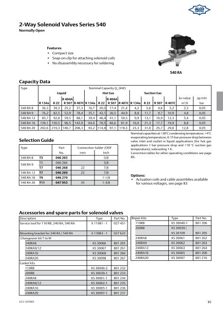
Features<br />
• Compact size<br />
• Snap-on clip for attaching solenoid coils<br />
• No disassembly necessary for soldering<br />
540 RA<br />
Type Nominal Capacity Q (kW)<br />
n<br />
Liquid Hot Gas Suction Gas<br />
R 404A R 404A kv-value ∆p min<br />
R 134a R 22 R 507 R 407C R 134a R 22 R 507 R 407C R 134a R 22 R 507 R 407C m<br />
Type Part Connection Solder /ODF<br />
Nominal capacities at +38°C condensing temperature, +4°C<br />
evaporating temperature, 0.15 bar pressure drop between<br />
valve inlet and outlet in liquid applications (for hot gas<br />
applications 1 bar pressure drop and +18 °C suction gas<br />
temperature); subcooling 1 K.<br />
No. mm Inch<br />
Correction tables for other operating conditions see page<br />
540 RA 8 T5 046 265 5/8<br />
86.<br />
540 RA 9<br />
T5 046 266 5/8<br />
T7 046 268 22 7/8<br />
3 /h bar<br />
540 RA 8 36,3 39,3 25,2 37,3 16,7 20,5 17,4 21,4 4,2 5,6 4,6 5,2 2,3 0,05<br />
540 RA 9 76,2 82,5 52,9 78,4 35,1 43,1 36,5 44,9 8,8 11,7 9,7 10,9 4,8 0,05<br />
540 RA 12 85,7 92,8 59,5 88,1 39,4 48,4 41,1 50,5 9,9 13,1 10,9 12,3 5,4 0,05<br />
540 RA 16 139,1 150,5 96,5 142,9 64,0 78,5 66,6 81,9 16,0 21,3 17,7 19,9 8,8 0,05<br />
540 RA 20 202,6 219,3 140,7 208,3 93,2 114,4 97,1 119,3 23,3 31,0 25,7 29,0 12,8 0,05<br />
540 RA 12 T7 046 269 22 7/8<br />
540 RA 16 T9 046 270 1-1/8<br />
540 RA 20 T11 047 953 35 1-3/8<br />
Accessories and spare parts for solenoid valves<br />
Description Type Part No.<br />
Service tool for 110 RB, 240 RA, 540 RA X 11981 - 1 027 451<br />
Mounting bracket for 240 RA / 540 RA<br />
Changeover kit T to M<br />
X 13983 - 1 027 622<br />
240RA8 KS 30066 801 265<br />
240RA9/12 KS 30067 801 261<br />
240RA16 KS 30068 801 266<br />
240RA20<br />
Gasket kits<br />
KS 30098 801 267<br />
110RB KS 30040-2 801 232<br />
200RB KS 30039-1 801 233<br />
240RA8 KS 30061-1 801 234<br />
240RA9/12 KS 30062-1 801 235<br />
240RA16 KS 30065-1 801 236<br />
240RA20 KS 30097-1 801 237<br />
Options:<br />
• Actuation coils and cable assemblies available<br />
for various voltages, see page 83<br />
Repair Kits Type Part No.<br />
110RB KS 30040-1 801 206<br />
200RB KS 30039 /<br />
KS 30109 801 205<br />
240RA8 KS 30061 801 262<br />
240RA9 KS 30062 801 263<br />
240RA12 KS 30063 801 264<br />
240RA16 KS 30065 801 200<br />
240RA20 KS 30097 801 216<br />
85


