Druck ADTS 505 Air Data Test Set - GE Measurement & Control
Druck ADTS 505 Air Data Test Set - GE Measurement & Control
Druck ADTS 505 Air Data Test Set - GE Measurement & Control

You also want an ePaper? Increase the reach of your titles
YUMPU automatically turns print PDFs into web optimized ePapers that Google loves.
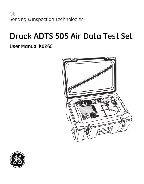
<strong>GE</strong><br />
Sensing & Inspection Technologies<br />
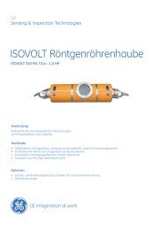
<strong>Druck</strong> <strong>ADTS</strong> <strong>505</strong> <strong>Air</strong> <strong>Data</strong> <strong>Test</strong> <strong>Set</strong><br />
User Manual K0260
© The General Electric Company. All rights reserved
i<br />
Introduction<br />
� This technical manual provides operating instructions for the <strong>Air</strong> <strong>Data</strong> <strong>Test</strong> System compatible<br />
with the requirements of first line operation for the technician and supervisor.<br />
Scope<br />
� This technical manual contains a brief description, operation and testing procedures for the<br />
user of this equipment with software version V1.07.<br />
Safety<br />
� The manufacturer has designed this equipment to be safe when operated using the<br />
procedures detailed in this manual. Do not use this equipment for any other purpose than that<br />
stated.<br />
� This publication contains operating and safety instructions that must be followed to make sure<br />
of safe operation and to maintain the equipment in a safe condition. The safety instructions<br />
are either warnings or cautions issued to protect the user and the equipment from injury or<br />
damage.<br />
� Use qualified* technicians and good engineering practice for all procedures in this publication.<br />
PIN Protection<br />
The <strong>ADTS</strong> <strong>505</strong> contains two protected menus, the operating limits (described in this manual)<br />
and the maintain calibration menu (described in the calibration manual).<br />
The factory set PIN codes are contained in an envelope addressed to the Supervisor.<br />
IMPORTANT NOTE<br />
Change these codes for authorised access. Unauthorised access to these two menus can make<br />
this system inaccurate and could, in control mode, cause excessive rates of pressure change.<br />
Pressure<br />
� Do not apply pressure greater than the maximum safe working pressure to the equipment.<br />
Toxic Materials<br />
There are no known toxic materials used in this equipment.<br />
Maintenance<br />
� The equipment must be maintained using the manufacturer’s procedures and should be<br />
carried out by authorized service agents or the manufacturer’s service departments<br />
Technical Advice<br />
� For technical advice contact the manufacturer or subsidiary.<br />
* A qualified technician must have the necessary technical knowledge, documentation, special test<br />
equipment and tools to carry out the required work on this equipment.<br />
K0260 Issue No. 6
<strong>Druck</strong> <strong>ADTS</strong> <strong>505</strong> User Manual<br />
Associated Publications<br />
This lists the <strong>Druck</strong> manuals and publications referenced in this manual.<br />
Calibration Manual K272<br />
<strong>Air</strong> <strong>Data</strong> <strong>Test</strong> <strong>Set</strong> <strong>ADTS</strong> <strong>505</strong><br />
Quick Reference Guide K274<br />
<strong>Air</strong> <strong>Data</strong> <strong>Test</strong> <strong>Set</strong> <strong>ADTS</strong> <strong>505</strong><br />
Approved Service Agents<br />
Internet www.gesensinginspection.com<br />
Markings and Symbols<br />
This symbol, on the test set, indicates that the user should refer to the user guide or manual.<br />
This symbol, in this manual set, indicates a hazard to the user.<br />
Do not dispose of this product as household<br />
waste. Refer to “Maintenance”.<br />
Complies with European Union directives.<br />
ii<br />
K0260 Issue No. 6
iii<br />
Table of Contents<br />
CONTENTS<br />
Preliminary pages<br />
Introduction .............................................................................................................................................................................. ............... i<br />
Scope .............................................................................................................................................................................. ............... i<br />
Associated Publication................................................................................................................................................................ ............... ii<br />
Approved Service Agents........................................................................................................................................................... ............... ii<br />
Table of contents (this table).................................................................................................................................................... ............... iii<br />
Abbreviations .............................................................................................................................................................................. ............... vii<br />
Glossary .............................................................................................................................................................................. ............... ix<br />
Pressure units and conversion factors................................................................................................................................ ............... xi<br />
ATEX Certified Advanced Hand Terminal........................................................................................................................... ............... xii<br />
Section Title page<br />
1 DESCRIPTION<br />
1.1 Introduction...................................................................................................................................................... ............... 1-1<br />
1.2 Operating Limits............................................................................................................................................. ............... 1-3<br />
2 INSTALLATION<br />
2.1 Packaging ........................................................................................................................................................ ............... 2-1<br />
2.2 Packaging for Storage and Transportation...................................................................................... ............... 2-1<br />
2.3 Return Goods Procedure............................................................................................................................ ............... 2-3<br />
2.4 Electrical Connection................................................................................................................................... ............... 2-6<br />
2.5 Pneumatic Pressure Connection............................................................................................................ ............... 2-7<br />
2.6 Positioning of the <strong>ADTS</strong> <strong>505</strong>...................................................................................................................... ............... 2-8<br />
3 OPERATION<br />
3.1 Preparation....................................................................................................................................................... ............... 3-1<br />
3.2 Display Functions and Units of Measure............................................................................................ ............... 3-2<br />
3.3 Quick Reference............................................................................................................................................. ............... 3-3<br />
3.4 First Time Operators..................................................................................................................................... ............... 3-4<br />
3.4.1..... Operating Modes........................................................................................................................... ............... 3-6<br />
3.5 Operation and Example Procedures.................................................................................................... ............... 3-10<br />
3.5.1..... Operating Procedures................................................................................................................. ............... 3-10<br />
3.5.2..... Power-up........................................................................................................................................... ............... 3-10<br />
3.5.3..... <strong>Control</strong> or Measure Parameter............................................................................................... ............... 3-11<br />
3.5.4..... Leak <strong>Test</strong>ing the <strong>ADTS</strong> <strong>505</strong>........................................................................................................ ............... 3-11<br />
3.5.5..... Changing the Units of <strong>Measurement</strong>................................................................................... ............... 3-13<br />
3.5.6..... <strong>Set</strong>ting Limits................................................................................................................................... ............... 3-13<br />
3.6 <strong>Test</strong>s Before Use............................................................................................................................................ ............... 3-15<br />
3.6.1..... <strong>Air</strong>craft System Protection........................................................................................................ ............... 3-15<br />
3.7 <strong>Test</strong>ing <strong>Air</strong>craft Systems or UUT............................................................................................................. ............... 3-15<br />
3.7.1..... <strong>Test</strong>ing the <strong>Air</strong>craft Static System.......................................................................................... ............... 3-16<br />
3.7.2..... <strong>Test</strong>ing the <strong>Air</strong>craft Pitot System............................................................................................ ............... 3-17<br />
3.7.3..... Combined <strong>Test</strong>ing of the <strong>Air</strong>craft Pitot and Static Systems....................................... ............... 3-18<br />
3.7.4..... Mach <strong>Test</strong> and Constant Mach............................................................................................... ............... 3-19<br />
3.7.5..... Leak <strong>Test</strong>ing..................................................................................................................................... ............... 3-20<br />
3.7.6..... <strong>Air</strong>speed Switch <strong>Test</strong>.................................................................................................................... ............... 3-21<br />
3.7.7..... Engine Pressure Ratio (EPR)...................................................................................................... ............... 3-22<br />
3.7.8..... Go To Ground.................................................................................................................................. ............... 3-23<br />
K0260 Issue No. 6
<strong>Druck</strong> <strong>ADTS</strong> <strong>505</strong> User Manual<br />
Table of Contents (contd)<br />
Section Title page<br />
3.8 Manual Venting of the <strong>Air</strong>craft Pitot and Static Systems............................................................ ............... 3-24<br />
3.9 <strong>ADTS</strong> <strong>505</strong> Options.......................................................................................................................................... ............... 3-24<br />
3.10 <strong>Set</strong>-up Reference........................................................................................................................................... ............... 3-25<br />
4 MAINTENANCE<br />
4.1 Introduction...................................................................................................................................................... ............... 4-1<br />
4.2 Materials and Tools....................................................................................................................................... ............... 4-2<br />
4.3 Maintenance Tasks....................................................................................................................................... ............... 4-3<br />
4.4 Routine Maintenance................................................................................................................................... ............... 4-4<br />
5 TESTING AND FAULT FINDING<br />
5.1 Introduction...................................................................................................................................................... ............... 5-1<br />
5.2 Standard Serviceability <strong>Test</strong>..................................................................................................................... ............... 5-2<br />
5.3 Fault Diagnosis............................................................................................................................................... ............... 5-3<br />
5.4 Warnings and Self-test Errors................................................................................................................. ............... 5-3<br />
5.5 Further <strong>Test</strong>ing................................................................................................................................................ ............... 5-6<br />
5.6 Fault Finding.................................................................................................................................................... ............... 5-14<br />
6 REFERENCE and SPECIFICATION<br />
6.1 Introduction...................................................................................................................................................... ............... 6-1<br />
6.2 Key-pad Selections and Functions........................................................................................................ ............... 6-1<br />
F1 - F6................................................................................................................................................................ ............... 6-1<br />
ALT/Ps................................................................................................................................................................ ............... 6-2<br />
SPEED Qc........................................................................................................................................................... ............... 6-2<br />
MACH................................................................................................................................................................. ............... 6-3<br />
ROC Ps RATE..................................................................................................................................................... ............... 6-3<br />
RATE ................................................................................................................................................................... ............... 6-4<br />
LEAK MEASURE/CONTROL......................................................................................................................... ............... 6-5<br />
GROUND............................................................................................................................................................. ............... 6-5<br />
0 to 9.................................................................................................................................................................. ............... 6-6<br />
-000.................................................................................................................................................................... ............... 6-6<br />
CLEAR/QUIT...................................................................................................................................................... ............... 6-6<br />
DELETE................................................................................................................................................................ ............... 6-6<br />
HELP................................................................................................................................................................... ............... 6-7<br />
ENTER ................................................................................................................................................................ ............... 6-7<br />
CLEAR/QUIT + ENTER (ABORT).................................................................................................................. ............... 6-7<br />
Main Menu........................................................................................................................................................ ............... 6-8<br />
[Rate Timer]...................................................................................................................................................... ............... 6-8<br />
[Units] ................................................................................................................................................................ ............... 6-9<br />
[EPR]................................................................................................................................................................... ............... 6-10<br />
[Hold] ................................................................................................................................................................. ............... 6-10<br />
Nudge [ or ]............................................................................................................................................. ............... 6-10<br />
6.3 SETUP ................................................................................................................................................................ ............... 6-11<br />
6.3.1..... <strong>Set</strong>-up 1 of 2..................................................................................................................................... ............... 6-11<br />
............... [Display],[Single, Dual, Quad, Hand Term] .......................................................................... ............... 6-11<br />
iv<br />
K0260 Issue No. 6
v<br />
Table of Contents (contd)<br />
CONTENTS<br />
Section Title page<br />
[Units] ................................................................................................................................................................ ............... 6-12<br />
[Limits]................................................................................................................................................................ ............... 6-13<br />
[Alt. Corr.]........................................................................................................................................................... ............... 6-15<br />
[Date Format].................................................................................................................................................. ............... 6-16<br />
6.3.2..... <strong>Set</strong>-up 2 of 2..................................................................................................................................... ............... 6-17<br />
............... [Operational Hours]...................................................................................................................... ............... 6-17<br />
............... [Software Versions]....................................................................................................................... ............... 6-17<br />
............... [Security]............................................................................................................................................ ............... 6-17<br />
............... [Maintain Calibration].................................................................................................................. ............... 6-17<br />
............... [Auto Leak]........................................................................................................................................ ............... 6-18<br />
6.4 Other Features................................................................................................................................................ ............... 6-19<br />
Elapsed Time Counter.................................................................................................................................. ............... 6-19<br />
............... Auto Zero........................................................................................................................................... ............... 6-19<br />
............... Hand Terminal Option A............................................................................................................. ............... 6-19<br />
............... Hand Terminal Option B............................................................................................................. ............... 6-19<br />
............... ...............Template Format for Creating <strong>Test</strong> Sequence Files...................................... ............... 6-32<br />
............... ...............Zone 2 Hazardous Area Definition......................................................................... ............... 6-40<br />
............... ...............Option B Advanced Hand Terminal Specification.......................................... ............... 6-41<br />
6.5 Specification..................................................................................................................................................... ............... 6-42<br />
K0260 Issue No. 6
<strong>Druck</strong> <strong>ADTS</strong> <strong>505</strong> User Manual<br />
Table of Illustrations<br />
Figure Title page<br />
1-1 <strong>ADTS</strong> <strong>505</strong> General View.............................................................................................................................. ............... 1-2<br />
2-1 <strong>ADTS</strong> <strong>505</strong> Accessories................................................................................................................................. ............... 2-4<br />
2-2 <strong>ADTS</strong> <strong>505</strong> Altitude Correction On-aircraft.......................................................................................... ............... 2-9<br />
2-3 <strong>ADTS</strong> <strong>505</strong> Altitude Correction Off-aircraft.......................................................................................... ............... 2-9<br />
2-4 <strong>ADTS</strong> <strong>505</strong> General View.............................................................................................................................. ............... 2-10<br />
3-1 Key-pad and Display.................................................................................................................................... ............... 3-3<br />
5-1 Fault Finding Chart....................................................................................................................................... ............... 5-4<br />
5-2 System Screen for Diagnosis................................................................................................................... ............... 5-7<br />
5-3 System Screen................................................................................................................................................ ............... 5-9<br />
5-4 Key-pad <strong>Test</strong> Display................................................................................................................................... ............... 5-10<br />
6-1 ARINC 565 Limits Graph............................................................................................................................. ............... 6-14<br />
6-2 Altitude Correction On-aircraft............................................................................................................... ............... 6-15<br />
6-3 Altitude Correction Off-aircraft............................................................................................................... ............... 6-16<br />
6-4 Interconnection.............................................................................................................................................. ............... 6-20<br />
6-5 Power-up Displays........................................................................................................................................ ............... 6-21<br />
6-6 Main Menu Screen........................................................................................................................................ ............... 6-22<br />
6-7 Main Menu Structure................................................................................................................................... ............... 6-23<br />
6-8 Manual <strong>Control</strong> Selections........................................................................................................................ ............... 6-24<br />
6-9 <strong>Set</strong>-up Menu Selections.............................................................................................................................. ............... 6-27<br />
6-10 <strong>Test</strong> Sequence Selections.......................................................................................................................... ............... 6-30<br />
6-11 Customer <strong>Test</strong> Sequence File Selections............................................................................................ ............... 6-31<br />
6-12 System Status.................................................................................................................................................. ............... 6-38<br />
6-13 Example Error Screen.................................................................................................................................. ............... 6-39<br />
List of Tables<br />
Table Title page<br />
2-1 Parts List............................................................................................................................................................ ............... 2-5<br />
4-1 Maintenance Chart....................................................................................................................................... ............... 4-1<br />
4-2 Materials List.................................................................................................................................................... ............... 4-2<br />
4-3 Tool and <strong>Test</strong> Equipment Requirements............................................................................................. ............... 4-2<br />
5-1 Fault Finding ................................................................................................................................................... ............... 5-5<br />
5-2 System Screen Information...................................................................................................................... ............... 5-8<br />
5-3 Error Messages............................................................................................................................................... ............... 5-14<br />
5-4 Warning Messages....................................................................................................................................... ............... 5-15<br />
vi<br />
K0260 Issue No. 6
vii<br />
Abbreviations<br />
Abbreviations<br />
The following abbreviations are used in this manual; the abbreviations are the same in the singular and plural.<br />
A Ampere<br />
abs Absolute<br />
a.c. Alternating current<br />
<strong>ADTS</strong> <strong>Air</strong> <strong>Data</strong> <strong>Test</strong> <strong>Set</strong><br />
ALT Altitude<br />
ARINC <strong>Air</strong> Radio Incorporated<br />
ASI <strong>Air</strong>speed indicator<br />
CAS Calibrated airspeed<br />
COSHH <strong>Control</strong> of Substances Hazardous to Health Regulations<br />
cm Centimetre<br />
d.c. Direct current<br />
Def Define<br />
e.g. For example<br />
EPR Engine pressure ratio<br />
etc. And so on<br />
°F Degrees Fahrenheit<br />
Fig. Figure<br />
ft Foot<br />
g Gauge<br />
h Hour<br />
HBC High breaking capacity<br />
Hg Mercury<br />
hm Hecto metre<br />
Hz Hertz<br />
IAS Indicated airspeed<br />
i.e. That is<br />
in Inch<br />
kg Kilogram<br />
km Kilometre<br />
kts Knots<br />
LCD Liquid crystal display<br />
m Metre<br />
mA Milliampere<br />
max Maximum<br />
mbar Millibar<br />
min Minute or minimum<br />
mm Millimetre<br />
mph Miles per hour<br />
MSDS Material safety data sheet<br />
mV Millivolts<br />
No. Number<br />
PIN Personal identification number<br />
Ps Static pressure<br />
psi Pounds per square inch<br />
Pt Total pressure (Pitot)<br />
Qc Differential pressure Ps-Pt<br />
QFE Local atmospheric pressure<br />
QNH Barometric pressure at sea level<br />
K0260 Issue No. 6
<strong>Druck</strong> <strong>ADTS</strong> <strong>505</strong> User Manual<br />
Abbreviations (contd)<br />
RGA Return Goods Authorization (<strong>Druck</strong> procedure)<br />
RMS Root mean square<br />
ROC Rate of climb<br />
Rt Rate<br />
SST Standard serviceability test<br />
V Volts<br />
+ve Positive<br />
-ve Negative<br />
°C Degrees Celsius<br />
°F Degrees Fahrenheit<br />
viii<br />
K0260 Issue No. 6
ix<br />
Terminology<br />
Glossary<br />
The terminology used in this manual is specific and individual interpretation must not be<br />
introduced. The terms are defined as follows:<br />
Adjust To bring to a more satisfactory state; to manipulate controls, levers, linkages, etc. to return equipment<br />
from an out-of-tolerance condition to an in-tolerance condition.<br />
Align To bring into line; to line up; to bring into precise adjustment, correct relative position or coincidence.<br />
Assemble:To fit and secure together the several parts of; to make or form by combining parts.<br />
Calibrate: To determine accuracy, deviation or variation by special measurement or by comparison with a<br />
standard.<br />
Check: Make a comparison of a measure of time, pressure, temperature, resistance, dimension or other<br />
quality with a known figure for that measurement.<br />
Disconnect:To detach the connection between; to separate keyed or matched equipment parts.<br />
Dismantle:To take apart to the level of the next smaller unit or down to all removable parts.<br />
Examine: To perform a critical visual observation or check for specific conditions; to test the condition of.<br />
Fit: Correctly attach one item to another.<br />
Inspect: Review the work carried out by Specialists to ensure it has been performed satisfactorily.<br />
Install: To perform operations necessary to properly fit an equipment unit into the next larger assembly or<br />
system.<br />
Maintain: To hold or keep in any particular state or condition especially in a state of efficiency or validity.<br />
Operate: Make sure that an item or system functions correctly as far as possible without the use of test<br />
equipment or reference to measurement.<br />
Readjust: To adjust again; to move back to a specified condition; to bring back to an in-tolerance condition.<br />
Reconnect:To rejoin or refasten that which has been separated.<br />
Refit: Fit an item which has previously been removed.<br />
Glossary<br />
K0260 Issue No. 6
<strong>Druck</strong> <strong>ADTS</strong> <strong>505</strong> User Manual<br />
Remove: To perform operations necessary to take an equipment unit out of the next larger assembly or<br />
system. To take off or eliminate. To take or move away.<br />
Repair: To restore damaged, worn out or malfunctioning equipment to a serviceable, usable or operable<br />
condition.<br />
Replace: Remove an item and fit a new or a serviced item.<br />
Reset: To put back into a desired position, adjustment or condition.<br />
Service: To perform such operations as cleaning, lubricating and replenishing to prepare for use.<br />
<strong>Test</strong>: Ascertain by using the appropriate test equipment that a component or system functions correctly.<br />
x<br />
K0260 Issue No. 6
xi<br />
Table of pressure units and conversion factors<br />
Unit Conversion<br />
To convert FROM pressure VALUE 1 in pressure UNITS 1<br />
TO pressure VALUE 2 in pressure UNITS 2, calculate as follows:<br />
Note:<br />
P ressure<br />
unit<br />
Factor ( Pascals)<br />
P ressure<br />
unit<br />
Factor<br />
( Pascals)<br />
2 bar100000 lbf/ ft<br />
47.<br />
8803<br />
2 lbf/ in<br />
( psi)<br />
6894. 76<br />
inHg 3386.<br />
39<br />
mH O 9806. 65<br />
inH O [ 1]<br />
249.<br />
089<br />
2 2<br />
mbar100 ftH O [ 1]<br />
2989.<br />
07<br />
2<br />
2 kgf/ cm<br />
98066. 5 atm 101325.<br />
0<br />
2 2 kgf/ m<br />
9. 80665<br />
pdl/ ft<br />
1.<br />
48816<br />
2 mmHg133. 322<br />
dyn/ cm<br />
0.<br />
1<br />
cmHg1333. 22<br />
hbar 10000000<br />
2 mHg133322. 0 tonf/ ft<br />
( UK)<br />
107252.<br />
0<br />
2 mm/ H O [ 1]<br />
9. 80665<br />
tonf/ in<br />
( UK)<br />
15444300<br />
2<br />
cm/ H O [ 1]<br />
98. 0665<br />
inH O ( USA)<br />
[ 2]<br />
248.<br />
64135<br />
2 2<br />
N/ m2<br />
1 ftH O ( USA)<br />
[ 2]<br />
2983.<br />
6983<br />
2<br />
2 hPa100 kP/ mm<br />
9806650<br />
2 kPa1000 kP/ cm<br />
98066.<br />
5<br />
2 MPa1000000 kP/ m<br />
9.<br />
80665<br />
torr133. 322<br />
VALUE 2 = VALUE 1 x FACTOR 1<br />
FACTOR 2<br />
The conversion factor for pressure units referenced [1] are calculated for a water temperature<br />
of 4°C. Pressure units referenced [2] are calculated for a water temperature of 68°F these units<br />
are normally used in the USA.<br />
K0260 Issue No. 6
<strong>Druck</strong> <strong>ADTS</strong> <strong>505</strong> User Manual<br />
ATEX Certified Advanced Hand Terminal (Option B)<br />
CONDITIONS OF USE<br />
The ATEX certified Advanced Hand Terminal can be used in zone 2 hazardous areas in accordance<br />
with the ATEX certification document and schedule.<br />
ATEX Certificate of Conformity<br />
No. Baseefa06ATEX0003<br />
BASEEFA being an Approved Certification Body, in accordance with Article 14 of the Council Directive<br />
of the European Communities of 18th December, 1975 (76/117/EEC) certifies that the apparatus<br />
has been found to comply with harmonised European Standards:<br />
EN 60079-0: 2004 EN 60079-15: 2005<br />
and has successfully met the examination and test requirements recorded in confidential report<br />
number:<br />
05(C)0663 (Baseefa) dated 6th February 2006<br />
Note:<br />
Refer to pages 2/2 of the Certificate of conformity for electrical connection parameters.<br />
Rated Voltage = 28Vdc.<br />
Marking detail:<br />
Refer to Advanced Hand Terminal User Manual K0418 and the label on the Advanced Hand Terminal.<br />
SPECIAL CONDITION OF USE<br />
• The advanced hand terminal must not be disconnected when energized in the hazardous area.<br />
• The advanced hand terminal is a non-serviceable component. If the advanced hand terminal becomes<br />
unserviceable it can only be replaced by another ATEX compliant hand terminal.<br />
Note:<br />
The advanced hand terminal must only be used with the cable assembly supplied and marked “DO<br />
NOT SEPARATE WHILST ENERGISED IN HAZARDOUS AREA”<br />
xii<br />
K0260 Issue No. 6
xiii<br />
intentionally left blank<br />
K0260 Issue No. 6
xiv<br />
K0260 Issue No. 6
Description 1 - 1<br />
1 INTRODUCTION<br />
1.1 Introduction<br />
� The <strong>ADTS</strong> <strong>505</strong> is a self-contained flight-line air data test system, enclosed in an ABS case. The<br />
unit provides complete pressure and vacuum measuring and control for on-aircraft sense<br />
and leak testing, functional tests of air data instruments, components and systems.<br />
� The <strong>ADTS</strong> <strong>505</strong> displays and operates in either units of pressure measurement or aeronautical<br />
units. In the control mode, the rate that the pressures change towards new set-points can<br />
be controlled in true aeronautical rate units.<br />
� There are two independent pneumatic channels connect to the aircraft or instrument systems,<br />
one for static and one for pitot. They can be operated as measure only channels with leak<br />
testing facilities or each can be control channels producing true pressure conditions for altitude<br />
and airspeed. Two pneumatic outlet ports, on the front panel and identified as Ps (static) and<br />
Pt (pitot) provide connection to the aircraft system or unit under test.<br />
� To protect sensitive instruments and equipment a `ground' facility automatically and safely<br />
controls both channels to atmospheric pressure at the previously entered rates of change<br />
and then informs the user when both channels are safely at `ground'.<br />
� Pre-defined sets of limits, stored in the system, prevent excessive pressures and rates<br />
damaging aircraft systems and components. A further five sets of operating limits can be<br />
defined by the supervisor or quality assurance engineer. The user can select sets of limits but<br />
cannot change the values.<br />
� The user interface is either the key-pad and display on the front panel or one of two types of<br />
optional hand terminal connected to the front panel. The two types of hand terminal are<br />
identified as option A and option B.<br />
� The option A hand terminal contains all the facilities of the front panel key-pad and display.<br />
The key-pad contains fixed function keys used to select various parameters, modes and enter<br />
numeric values. The display shows various menus, each menu provides selections using six<br />
menu-defined function keys.<br />
� The option B advanced hand terminal is ATEX certified for use in zone 2 hazardous areas. This<br />
computer-based hand terminal up-loads and down-loads user-defined test programs<br />
displaying all test data on a touch-sensitive, Windows® display, colour screen.<br />
� The integral pumps of the <strong>ADTS</strong> <strong>505</strong>, produce pressure and vacuum supplies for the unit's<br />
controlling requirements. The power supply connection for the unit is located on the front<br />
panel.<br />
K0260 Issue No. 6<br />
1
1 - 2 <strong>Druck</strong> <strong>ADTS</strong> <strong>505</strong> User Manual<br />
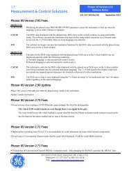
DO NOT OBSTRUCT<br />
THESE VENTS<br />
WATER<br />
DRAIN<br />
K0260 Issue No. 6<br />
FIGURE 1-1 <strong>ADTS</strong> <strong>505</strong> <strong>GE</strong>NERAL VIEW<br />
Mach<br />
<strong>Air</strong> <strong>Data</strong> <strong>Test</strong> <strong>Set</strong> - Hand Terminal<br />
Leak Measure<br />
0.001 Mach<br />
LEAK MEASURE MODE<br />
Option A Hand Terminal<br />
g<br />
Advanced Advanced Hand Hand Terminal Terminal<br />
Option B Hand Terminal
Description 1 - 3<br />
1.2 Operating Limits<br />
The <strong>ADTS</strong> <strong>505</strong> is supplied with the following pre-defined operating limits.<br />
Civil Limits<br />
Parameter Limit<br />
MIN ALT -1,000 ft<br />
MAX ALT 50,000 ft<br />
MIN CAS 0.0 knots<br />
MAX CAS 450.0 knots<br />
MAX MACH 1.000 Mach<br />
MAX ROC 6,000 ft/min<br />
ARINC LIMITS OFF<br />
ALT CORRECTION 0 ft<br />
MIN Ps 115.972 mbar<br />
MAX Ps 1050.406 mbar<br />
MIN Qc 0.0 mbar<br />
MAX Qc 368.01 mbar<br />
MAX Rate Ps 109.85 mbar/min<br />
MAX Rate Qc<br />
Standard Limits<br />
109.85 mbar/min<br />
Parameter Limit<br />
MIN ALT -2,000 ft<br />
MAX ALT 60,000 ft<br />
MIN CAS 0.0 knots<br />
MAX CAS 650.0 knots<br />
MAX MACH 1.732 Mach<br />
MAX ROC 10,000 ft/min<br />
ARINC LIMITS OFF<br />
ALT CORRECTION 0 ft<br />
MIN Ps 65.00 mbar<br />
MAX Ps 1088.6 mbar<br />
MIN Qc 0.0 mbar<br />
MAX Qc 866.00 mbar<br />
MAX Rate Ps 200 mbar/min<br />
MAX Rate Qc 200 mbar/min<br />
K0260 Issue No. 6<br />
1
1 - 4 <strong>Druck</strong> <strong>ADTS</strong> <strong>505</strong> User Manual<br />
Max Limits<br />
Parameter Limit<br />
MIN ALT -2,000 ft<br />
MAX ALT 60,000 ft<br />
MIN CAS 0.0 knots<br />
MAX CAS 650.0 knots<br />
MAX MACH 2.800 Mach<br />
MAX ROC 40,000 ft/min<br />
ARINC LIMITS OFF<br />
ALT CORRECTION 0 ft<br />
MIN Ps 10.90 mbar<br />
MAX Ps 1355.00 mbar<br />
MIN Qc -1355.00 mbar<br />
MAX Qc 2490.00 mbar<br />
MAX Rate Ps 1000 mbar/min<br />
MAX Rate Qc 1000 mbar/min<br />
EPR Limits<br />
Parameter Limit<br />
MIN INLET 27.0 mbar<br />
MAX INLET 1355.0 mbar<br />
MIN OUTLET 27.0 mbar<br />
MAX OUTLET 2500.0 mbar<br />
MIN EPR 0.1<br />
MAX EPR 10.0<br />
MIN INLET RATE 0<br />
MAX INLET RATE 1000 mbar/min<br />
MIN EPR RATE 0<br />
MAX EPR RATE 60 EPR/min<br />
K0260 Issue No. 6
<strong>Druck</strong> <strong>ADTS</strong> <strong>505</strong> User Manual 2 - 1<br />
2 INSTALLATION<br />
2.1 Packaging<br />
On receipt of the <strong>ADTS</strong> <strong>505</strong> check the contents of the packaging against the following lists:<br />
i) <strong>ADTS</strong> <strong>505</strong> <strong>Air</strong> <strong>Data</strong> <strong>Test</strong> <strong>Set</strong><br />
ii) Power supply cable - 5 m<br />
iii) Option A<br />
comprising:<br />
Hand terminal<br />
Hand terminal cable - 18 m (option A only)<br />
5 m hose - red<br />
5 m hose - blue<br />
Accessory Bag<br />
iv) Option B<br />
comprising:<br />
Advanced hand terminal<br />
Hand terminal cable - 18 m (option B only)<br />
Cable, communications<br />
Cable, power supply<br />
Power pack<br />
Accessory Bag<br />
v) 2 m hose - red<br />
vi) 2 m hose - blue<br />
vii) User Manual (this publication)<br />
viii) Quick Reference Guide K274<br />
ix) Calibration Manual K272<br />
x) Spare fuses (2 off)<br />
2.2 Packaging for Storage or Transportation<br />
To store the unit or to return the unit for calibration or repair carry out the following procedures:<br />
1. Pack the unit as detailed in the following procedure.<br />
2. To return the unit for calibration or repair complete the return goods procedure as<br />
detailed in 2.3.<br />
K0260 Issue No. 6<br />
2
2 - 2 Installation<br />
Procedure<br />
� The unit should be at zero/ambient pressure. Disconnect the hose assemblies and stow in the<br />
lid.<br />
� Switch OFF and disconnect from the electrical power supply. Disconnect the power<br />
supply cable and the hand terminal cable. Disconnect the hand terminal cable from the<br />
hand terminal.<br />
� Fit the lid to the unit.<br />
� The power supply cable, hand terminal cable and the hand terminal should be placed<br />
in the original packing material.<br />
� If available, use the original packing material. When using packing materials other than the<br />
original, proceed as follows.<br />
� Wrap unit in polyethylene sheeting.<br />
� Select a double-wall cardboard container. Inside dimensions must be at least 15 cm<br />
greater than the equipment. The carton must meet test strength requirements of >125 kg.<br />
� Protect all sides with shock-absorbing material to prevent equipment movement within<br />
the container.<br />
� Seal carton with approved sealing tape.<br />
� Mark carton “FRAGILE” on all sides, top, and bottom of shipping container.<br />
� To return the unit for calibration or repair complete the return goods procedure as detailed in 2.3.<br />
Environment<br />
� The following conditions apply for both shipping and storage:<br />
� Temperature Range........... ............-20 to +70 °C (-4 to +158 °F)<br />
� Altitude......... ............Up to 15,000 feet (4,570 metres)<br />
K0260 Issue No. 6
<strong>Druck</strong> <strong>ADTS</strong> <strong>505</strong> User Manual 2 - 3<br />
2.3 Returned Goods Procedure<br />
Should the unit require calibration or become unserviceable it can be returned to the <strong>Druck</strong><br />
Service Department.<br />
Please contact our Service Department, either by 'phone, fax or E-mail, to obtain a Returned<br />
Goods Authorization (RGA) number or (Return Material Authorization [RMA] in USA), providing<br />
the following information:<br />
Product (i.e. <strong>ADTS</strong> <strong>505</strong>)<br />
Serial number<br />
Details of defect/work to be undertaken<br />
Calibration traceability requirements<br />
Operating conditions<br />
Safety Precautions<br />
You must also tell us if the product has been in contact with anything hazardous or toxic and,<br />
the relevant COSHH (MSDS in USA) references and precautions to be taken when handling.<br />
IMPORTANT NOTICE<br />
Service or calibration by unauthorized sources will affect the warranty and may not guarantee<br />
further performance<br />
K0260 Issue No. 6<br />
2
2 - 4 Installation<br />
1<br />
K0260 Issue No. 6<br />
191-198<br />
�<br />
6<br />
12<br />
Mach<br />
<strong>Air</strong> <strong>Data</strong> <strong>Test</strong> <strong>Set</strong> - Hand Terminal<br />
Leak Measure<br />
LEAK MEASURE MODE<br />
11<br />
0.001 Mach<br />
13<br />
9<br />
18m<br />
Advanced Advanced Hand Hand Terminal Terminal<br />
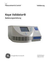
FIGURE 2-1 <strong>ADTS</strong> <strong>505</strong> ACCESSORIES<br />
g<br />
4<br />
18m<br />
�<br />
10<br />
5<br />
2<br />
3A<br />
DO NOT SEPARATE WHILST<br />
ENERGISED IN HAZARDOUS AREA<br />
Note: Item 13 supplied for the country of use
<strong>Druck</strong> <strong>ADTS</strong> <strong>505</strong> User Manual 2 - 5<br />
No Part Number Description<br />
# not illustrated<br />
1 AS<strong>505</strong>-18-3124M0 Kit, Fuse/ O-Ring 1<br />
2 AS<strong>505</strong>-52-3124M0<br />
TABLE 2-1 PARTS LIST<br />
Qty per<br />
assy<br />
Comprising:<br />
Hose, red, ST/OPN, AN4<br />
1<br />
Hose, blue, ST/OPN, AN4 1<br />
3A AS<strong>505</strong>-40-3124M0 Cable, AC Power, 5M (250V UK plug) 1<br />
3B# AS<strong>505</strong>-41-3124M0<br />
3C# AS<strong>505</strong>-42-3124M0<br />
4 AS<strong>505</strong>-56-3124M0<br />
4.1# -<br />
5 AS<strong>505</strong>-54-3124M0<br />
Alternative<br />
AC Power, 5M (115V US plug)<br />
Alternative<br />
AC Power, 5M (250V European plug)<br />
Option A<br />
Hand terminal Assembly<br />
Option A and B<br />
Hose, red, 5M<br />
Hose, blue, 5M<br />
Option A<br />
Cable, Hand terminal 18M (option)<br />
6 AS<strong>505</strong>-57-3124M0<br />
Option A and B<br />
Bag, Accessory, Hand Terminal<br />
1<br />
7# AS<strong>505</strong>-60-3124M0 Handbook, User Manual, K0260 1<br />
8# AS<strong>505</strong>-61-3124M0 Handbook, Calibration Manual, K0272 1<br />
9 AS<strong>505</strong>-56-3124M1<br />
10 AS<strong>505</strong>-54-3124M1<br />
Option B<br />
Hand terminal , Advanced<br />
Option B<br />
Cable, Hand terminal 18M, Safety marking (option)<br />
11 AS204-06-3435M0 Cable, Communications PC 1<br />
12 AS204-07-3435M0 Power pack 1<br />
13<br />
part of item 12<br />
Adaptor, power pack (comprising: 4)<br />
14# AS204-10-3435M0 Stylus, pack (comprising: 3)<br />
1<br />
1<br />
1<br />
1<br />
1<br />
1<br />
1<br />
1<br />
K0260 Issue No. 6<br />
2
2 - 6 Installation<br />
2.4 Electrical Connection<br />
WARNING: VOLTA<strong>GE</strong>S IN EXCESS OF 30 VOLTS (RMS) AC OR 50 VOLTS DC, IN CERTAIN<br />
CIRCUMSTANCES, CAN BE LETHAL. CARE MUST BE TAKEN WHEN WORKING ON LIVE,<br />
EXPOSED CONDUCTORS.<br />
Power Supply Connection<br />
The unit must be connected to the correct electrical power supply as stated, adjacent to the<br />
power connector.<br />
CAUTIONS:<br />
1 THE SUPPLY MUST PROVIDE CONNECTION TO A PROTECTIVE GROUND TERMINAL. THE UNIT MUST, AT ALL<br />
TIMES, BE CONNECTED TO THE SUPPLY EARTH (GROUND).<br />
2 THE POWER SUPPLY CABLE AND CONNECTOR MUST BE CORRECTLY RATED FOR THE POWER SUPPLY.<br />
Note: The <strong>ADTS</strong> <strong>505</strong> is normally supplied with an approved power supply cable for use in the country<br />
of delivery. This can limit the maximum supply voltage that can be safely used.<br />
e.g. a NEMA 5-15P terminated cable, for use in the U.S.A., is approved for a maximum of 125<br />
V ac; it must be replaced for a higher supply voltage.<br />
� Make sure that the power supply is off before connecting the power cable.<br />
� If required, connect the hand terminal to the connector on the front panel.<br />
Note: Connecting the hand terminal to the unit disables the front panel key-pad.<br />
Fuses<br />
The two fuses, located in the holders and mounted on the front panel, protect the unit. The<br />
fuses are connected in the live and neutral supply circuit and are rated at:<br />
5A anti-surge HBC 250V<br />
External earth/ground connection<br />
� An external earth (ground) cable may be connected to the stud on the front panel of the unit<br />
providing integrity of the earth (ground) connection.<br />
K0260 Issue No. 6<br />
Pin<br />
(<strong>ADTS</strong>)<br />
European<br />
Colour<br />
U.S.<br />
Color<br />
Function<br />
1 Brown Black Live<br />
4 Blue White Neutral<br />
Centre Green/Yellow Green Protective Earth (Ground)
<strong>Druck</strong> <strong>ADTS</strong> <strong>505</strong> User Manual 2 - 7<br />
Option B - Advanced Hand Terminal<br />
WARNING: DO NOT DISCONNECT THE ADVANCED HAND TERMINAL WHEN ENERGIZED IN THE<br />
HAZARDOUS AREA.<br />
USE IN A HAZARDOUS AREA<br />
SPECIAL CONDITIONS APPLY TO THIS ATEX CERTIFIED ADVANCED HAND TERMINAL REFER TO PA<strong>GE</strong> VI.<br />
Connection<br />
• The <strong>ADTS</strong> <strong>505</strong> provides a power supply to the advanced hand terminal when connected to the<br />
hand terminal connector on the front panel.<br />
• The power supplies must be isolated when connecting the advanced hand terminal in the<br />
hazardous area.<br />
Using the advanced hand terminal when not connected to the <strong>ADTS</strong> <strong>505</strong><br />
Using the advanced hand terminal with a pc to create test scripts.<br />
• The unit must be connected to the correct electrical power supply, see paragraph 2.4.<br />
• Before use, make sure the SELV power adaptor supplied with the instrument is correct for the<br />
power supply voltage. The Safety Extra Low Voltage (SELV) power adaptor complies with<br />
EN61010 (including safety requirements for laboratory instruments).<br />
Note: The instrument can be powered from other DC power supplies of the correct voltage range. It<br />
is the user’s responsibility to make sure the power supply is safe.<br />
� Make sure that the power supply is off before connecting the power cable.<br />
Communications Connection<br />
Communications cable - parts list item 11<br />
Pin No.<br />
<strong>ADTS</strong><br />
1<br />
2<br />
3<br />
4<br />
5<br />
0V<br />
Function Connector Cable<br />
Colour<br />
+ VIN<br />
RS232 Tx PIN 2<br />
RS232 Rx<br />
RS232 0V<br />
Jack plug outer<br />
Jack plug inner<br />
PIN 3<br />
BLK<br />
BLK-W<br />
RED<br />
GRN<br />
PIN 5 BLK<br />
K0260 Issue No. 6<br />
2
2 - 8 Installation<br />
2.5 Pneumatic Pressure Connections<br />
Ps (static)- AN4 (MS33656-4)<br />
Pt (pitot)- AN4 (MS33656-4)<br />
When not in use, a blanking cap must be fitted.<br />
Note: When carrying out a leak test, a leak of this blanking cap affects the performance of the <strong>ADTS</strong> <strong>505</strong>.<br />
2.6 Positioning of the <strong>ADTS</strong> <strong>505</strong><br />
WARNING: IN AN ENCLOSED AREA WITH FUEL VAPOUR PRESENT THIS EQUIPMENT MUST BE<br />
PLACED AT LEAST 0.5 METRES ABOVE FLOOR LEVEL. THIS EQUIPMENT CONTAINS A<br />
D.C. MOTOR WITH BRUSHES THAT COULD CAUSE A SPARK.<br />
CAUTION: TO OPERATE, PLACE THE UNIT ON A HORIZONTAL SURFACE (FRONT PANEL UPPERMOST) OR VERTICALLY<br />
(POWER SUPPLY CONNECTOR UPPERMOST) THIS ALLOWS THE WATER IN THE WATER FILTER TO VENT. WATER<br />
COULD CONTAMINATE THE CONTROLLER MANIFOLD AND AFFECT CONTROLLER PERFORMANCE.<br />
Note: In control mode, the water drain, located at one end of the unit near the carrying handle, produces<br />
a flow of air and some water. The amount of water depends on the humidity and the operating<br />
time in control mode.<br />
CAUTION: BEFORE USE, CHECK THE WATER DRAIN PIPE, IT MUST BE FREE OF OBSTRUCTION. WHEN IN CONTROL<br />
MODE CHECK THAT A SMALL FLOW OF AIR COMES OUT OF THE DRAIN PIPE.<br />
Notes:<br />
1 When checking for a small flow of air do not block the drain pipe completely this causes a backpressure<br />
in the pipe and controller instability.<br />
2 If no air flows from the drain pipe, when in control mode, switch off and start again. If no air<br />
flows after a re-start, switch off and do not use the <strong>ADTS</strong> <strong>505</strong>, return the unit to the repair depot.<br />
CAUTION: THE SIDE VENTS MUST NOT BE OBSTRUCTED, THIS UNIT REQUIRES AN AIRFLOW FOR THE INTERNAL COOLING<br />
FANS.<br />
� It is important that the position of the <strong>ADTS</strong> <strong>505</strong> in relation to the aircraft altitude sensors is<br />
known. An altitude correction must be made to allow for the difference in height between the<br />
reference level and the aircraft's altitude sensors (Figures 2-2 and 2-3). The Reference section<br />
contains details of altitude correction.<br />
WARNING: OBSERVE THE APPROPRIATE SAFETY INSTRUCTIONS AND TESTING PROCEDURES<br />
DETAILED IN THE AIRCRAFT MAINTENANCE MANUALS AND COMPONENT<br />
MAINTENANCE MANUALS.<br />
K0260 Issue No. 6
<strong>Druck</strong> <strong>ADTS</strong> <strong>505</strong> User Manual 2 - 9<br />
FIGURE 2-2 <strong>ADTS</strong> <strong>505</strong> ALTITUDE CORRECTION ON-AIRCRAFT<br />
FIGURE 2-3 ALTITUDE CORRECTION OFF-AIRCRAFT<br />
K0260 Issue No. 6<br />
2
2 - 10 Installation<br />
K0260 Issue No. 6<br />
FIGURE 2-4 <strong>ADTS</strong> <strong>505</strong> <strong>GE</strong>NERAL VIEW
<strong>Druck</strong> <strong>ADTS</strong> <strong>505</strong> User Manual 3 - 1<br />
3 OPERATION<br />
3.1 Preparation<br />
WARNING:<br />
OBSERVE SAFETY PRECAUTIONS STATED IN LOCAL ORDERS AND THE AIRCRAFT OR<br />
EQUIPMENT SERVICING PROCEDURES.<br />
� Make sure the electrical and pneumatic connectors, electrical cables and pipes and positioning of<br />
the <strong>ADTS</strong> <strong>505</strong> comply with the instructions and requirements in Section 2 Installation.<br />
� Carry out the following before use:<br />
� If necessary, carry out the maintenance task detailed in Section 4.<br />
� Make sure the air data test system power supply switch on the front panel is set to<br />
OFF. Connect the air data test system to the electrical supply, make sure the supply<br />
includes a connection to a protective earth.<br />
� Inspect the pneumatic hoses for damage, ingress of dirt and moisture. Make sure<br />
the aircraft adaptors are serviceable and the pipe connections are air-tight.<br />
Note: Do not connect the air data test system to a contaminated aircraft system. Inspect the static<br />
vents and pitot probes for dirt and debris before connecting. If necessary, check the pitot-static<br />
system water drain traps.<br />
� Connect, to the air data test system, the hoses necessary for the test procedures to be carried out:<br />
STATIC output (Ps), PITOT output (Pt). Temporarily seal the free ends of the hoses.<br />
Note: When connected, take care not to kink or stand on the hoses.<br />
� Before use, the <strong>ADTS</strong> <strong>505</strong> should be tested, for first time users see section 3.4, for users requiring<br />
more operating detail see section 3.5.<br />
� This section contains a quick reference chart detailing all the functions of the key-pad. Further<br />
quick reference charts, at the end of this section, detail the set-up menu.<br />
� Review and become familiar with the whole procedure before starting the test process on an<br />
aircraft or component.<br />
K0260 Issue No. 6<br />
3
3 - 2 Operation<br />
3.2 Display Functions and Units of Measure<br />
When operating in either pressure measuring or pressure controlling modes, the <strong>ADTS</strong> <strong>505</strong> can<br />
display the following information:<br />
Aeronautical Functions Display Abbreviation Displayed Units<br />
K0260 Issue No. 6<br />
(if applicable)<br />
Altitude ALT ft, m<br />
Calibrated <strong>Air</strong>speed CAS kts, km/h, mph<br />
Mach MACH-<br />
Rate of Climb ROC ft/min, m/min, m/s, hm/min<br />
Rate of <strong>Air</strong>speed Rt CAS kts/min, km/h/min, mph/min<br />
Pressure Functions Display Abbreviation Displayed Units<br />
(if applicable)<br />
Static (Absolute) Ps [P]<br />
Pitot (Absolute)<br />
Dynamic or Impact<br />
Pt [P]<br />
(Differential) Qc [P]<br />
Engine Pressure Ratio EPR -<br />
Rate of Ps Rt Ps [P] /min<br />
Rate of Pt Rt Pt [P] /min<br />
Rate of Qc Rt Qc [P] /min<br />
Rate of EPR Rt EPR EPR/min<br />
Where [P] is the currently selected pressure units from the following list:<br />
mbar, inHg, mmHg, inH 2 O (4°C), inH 2 O (20°C), inH 2 O (60°F), psi, hPa, kPa.<br />
Operating Range and Performance<br />
The <strong>ADTS</strong> <strong>505</strong> is supplied with a full-scale range of 650 knots for measurement and control of the<br />
pitot pressure channel. The unit can measure altitude up to 105,000 ft; altitude control depends<br />
on the performance of the pump, the integral pump is capable of achieving -2000 to 60,000 ft.<br />
Refer to section 6 for more details of performance and specification.<br />
<strong>Set</strong>s of factory-defined limits known as ARINC565, Standard, Military, Max and EPR can be selected<br />
through the SETUP menu (see Reference section 6). Operators may also define up to five sets of<br />
additional limits for different aircraft types. When configuring the display to aeronautical or<br />
pressure units operators should be aware that when units of pressure are selected, wider full-scale<br />
pressure limits will be enabled for some parameters.
<strong>Druck</strong> <strong>ADTS</strong> <strong>505</strong> User Manual 3 - 3<br />
3.3 Quick Reference<br />
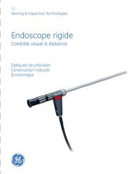
KEY-PAD FUNCTION<br />
the display shows the main pressure display (Leak Measure or <strong>Control</strong> mode) with<br />
normal operation key functions.<br />
Key/selection Function and comments<br />
F1-F6 Function keys for menus<br />
ALT/Ps Altitude (Aeronautical units) or Ps (pressure units)<br />
SPEED Qc <strong>Air</strong>speed (Aeronautical units) or Qc (pressure units)<br />
EPR Engine Pressure Ratio (pressure units only)<br />
ROC/RATE Ps Rate of Climb (Aeronautical units) or Rate of Ps (pressure units)<br />
LEAK MEASURE/CONTROL Switches between measure mode (for leak testing) and control mode<br />
RATE Rate of change of Pitot or Mach parameter, press parameter then RATE (read only)<br />
GROUND <strong>Control</strong>s Ps to atmospheric pressure and Qc to zero both at current rates of change<br />
SETUP Changes functions, limits and units, if [save/lock] pressed changes are permanent<br />
HELP Press HELP for further information on current selection/display<br />
0-9 Number entry<br />
-/000 Minus sign for first number entry 000 (thousand) if not first number of entry<br />
CLEAR/QUIT Clear number entry - quit from menu, HELP screen or clear warning message<br />
ENTER Complete number entry<br />
DELETE Removes the last number or character entered<br />
CLEAR/QUIT + DELETE = ABORT, all operations stop, the <strong>ADTS</strong> <strong>505</strong> restarts from a normal power-up<br />
sequence, including safe equalising of pressures between the test set and the<br />
connected system<br />
FIGURE 3-1 KEY-PAD AND DISPLAY<br />
K0260 Issue No. 6<br />
3
3 - 4 Operation<br />
3.4 First Time Operators<br />
� The following sequences of operation should be used by first time operators and by operators that<br />
use the equipment occasionally. For regular users, familiar with the equipment, go to section 3.5.<br />
<strong>Set</strong> the power supply switch to ON and the power-on routine starts.<br />
(1) The display first shows:<br />
(2) After approximately five seconds the display shows<br />
the start of the power-on sequence, the system<br />
carries out a self test. If the test finds a fault, the<br />
display shows an error message, refer to Section 5,<br />
Fault Finding and <strong>Test</strong>ing.<br />
(3) The display messages show a sequence of<br />
pneumatic and internal system checks:<br />
(4) After a successful self-test sequence the system changes to measure mode. The display changes<br />
to the Leak Measure mode display showing the parameters selected in set-up.<br />
K0260 Issue No. 6<br />
ALT<br />
Ps<br />
ROC<br />
RATE Ps<br />
LEAK<br />
MEASURE<br />
CONTROL<br />
SYSTEM STARTING<br />
SPEED<br />
Qc<br />
PLEASE WAIT<br />
MACH<br />
Pt<br />
GROUND RATE<br />
HELP SETUP<br />
7<br />
4<br />
1<br />
_<br />
000<br />
8<br />
5<br />
2<br />
0<br />
9<br />
6<br />
3<br />
.<br />
F1<br />
F2<br />
F3<br />
F4<br />
F5<br />
F6<br />
CLEAR<br />
QUIT<br />
ABORT<br />
DELETE<br />
ENTER
<strong>Druck</strong> <strong>ADTS</strong> <strong>505</strong> User Manual 3 - 5<br />
(5) The system is now ready for use.<br />
NOTES<br />
1 The <strong>ADTS</strong> <strong>505</strong> is a continuous, self-monitoring system. If the system detects an error, the display<br />
shows an error message. Lists of errors are detailed in Section 5, Fault Finding and <strong>Test</strong>ing.<br />
2 The display at power-up will be [QUAD] format (see above) unless changed in SETUP and [Save<br />
<strong>Set</strong>tings] selected.<br />
(6) The connection of an optional hand terminal (option A or B) causes the front panel display to show<br />
one of two messages:<br />
or<br />
ALT<br />
Ps<br />
ROC<br />
RATE Ps<br />
LEAK<br />
MEASURE<br />
CONTROL<br />
SPEED<br />
Qc<br />
REMOTE<br />
HAND<br />
TERMINAL<br />
OPERATING<br />
MACH<br />
Pt<br />
GROUND RATE<br />
HELP SETUP<br />
7<br />
8<br />
4 5<br />
1 2<br />
_<br />
000 0<br />
F1<br />
F2<br />
F3<br />
F4<br />
F5<br />
F6<br />
CLEAR 9 QUIT<br />
6 ABORT<br />
3 DELETE<br />
. ENTER<br />
To change between<br />
these two displays, see<br />
SETUP and<br />
[Display], [Hand Term],<br />
[Monitor] or [Message].<br />
See paragraphs 3.4.1<br />
and 3.9.<br />
K0260 Issue No. 6<br />
3
3 - 6 Operation<br />
3.4.1 Operating Modes<br />
The air data test system can now be set for a variety of functions and modes. In the following,<br />
examples of measure mode, control mode, leak measure mode and go-to-ground show the key<br />
presses and selections required for each mode.<br />
Measure Mode<br />
The system automatically enters measure mode after a successful self-test. To change the display<br />
press:<br />
To set the display to show [Monitor]<br />
or [Message] press F6. This<br />
switches between the two settings<br />
and operates only when the hand<br />
terminal is connected.<br />
To store display for the next power-up press:<br />
To return to measure mode press:<br />
K0260 Issue No. 6
<strong>Druck</strong> <strong>ADTS</strong> <strong>505</strong> User Manual 3 - 7<br />
Checking the Limits<br />
Before use on aircraft systems or components check that the limits are within the values stated<br />
in the appropriate maintenance manual. There are sets of factory-defined limits:<br />
Civil, Standard, Max or EPR (refer to Section 1 for details)<br />
At each power-up sequence the default set of limits "CIVIL" become active. The "CIVIL" limit set<br />
contains the lowest ranges and values. To see the name of the set of limits in use, press SETUP<br />
the display shows the [name] in the F3 limits field. To see the value of limits in use proceed as follows:<br />
ALT<br />
Ps<br />
ROC<br />
RATE Ps<br />
LEAK<br />
MEASURE<br />
CONTROL<br />
Active Limit <strong>Set</strong>: CIVIL<br />
Available Preset Limits<br />
MAX<br />
STANDARD<br />
CIVIL<br />
Available User Limits<br />
USER 1<br />
USER 2<br />
USER 3<br />
USER 4<br />
USER 5<br />
The current selected limits can be viewed by pressing F3. To select and use one of the factorydefined<br />
limit sets or define one of five sets of user-defined limits, see 3.5.6. The selected set of<br />
limits remain active until the selection of another set of limits or until power supply switch-off.<br />
ALT<br />
Ps<br />
ROC<br />
RATE Ps<br />
LEAK<br />
MEASURE<br />
CONTROL<br />
Min ALT -1000 ft<br />
Max ALT 50,000 ft<br />
Min CAS<br />
0.0 knots<br />
Max CAS 450 knots<br />
Max Mach 1.0 Mach<br />
Max ROC 6,000 ft/min<br />
Alt Cor. 0 ft<br />
ARINC Limits<br />
Page #1<br />
OFF<br />
SPEED<br />
Qc<br />
MACH<br />
Pt<br />
GROUND RATE<br />
HELP SETUP<br />
7 8<br />
4 5<br />
1 2<br />
_<br />
000 0<br />
User<br />
Details<br />
Next<br />
Page<br />
9<br />
6<br />
3<br />
.<br />
F1<br />
F2<br />
F3<br />
F4<br />
F5<br />
F6<br />
CLEAR<br />
QUIT<br />
ABORT<br />
DELETE<br />
ENTER<br />
Details<br />
Next<br />
Page<br />
�<br />
�<br />
Modify<br />
Units<br />
ft kts<br />
ft/min<br />
more<br />
(1 of 2)<br />
Supervisor<br />
Detail<br />
SPEED<br />
Qc<br />
MACH<br />
Pt<br />
GROUND RATE<br />
m km/h<br />
m/min<br />
HELP SETUP<br />
mbar<br />
mbar/min<br />
more<br />
(2 of 2)<br />
ALT<br />
Ps<br />
ROC<br />
RATE Ps<br />
LEAK<br />
MEASURE<br />
CONTROL<br />
Page #2<br />
7<br />
4<br />
1<br />
_<br />
000<br />
SPEED<br />
Qc<br />
MACH<br />
Pt<br />
GROUND RATE<br />
HELP SETUP<br />
Limits<br />
�<br />
�<br />
Select<br />
Limits<br />
View<br />
Details<br />
Enter<br />
PIN<br />
8<br />
5<br />
2<br />
0<br />
User Supervisor<br />
9<br />
6<br />
3<br />
.<br />
F1<br />
F2<br />
F3<br />
F4<br />
F5<br />
F6<br />
CLEAR<br />
QUIT<br />
ABORT<br />
DELETE<br />
ENTER<br />
7 8<br />
4 5<br />
1 2<br />
_<br />
000 0<br />
User<br />
Min Ps<br />
Max Ps<br />
Min Qc<br />
115.97 mbar<br />
1050.41 mbar<br />
0.0 mbar<br />
Details<br />
Next<br />
Page<br />
Max Qc 368.01 mbar<br />
Rt Ps 100.00 mbar/min<br />
Rt Qc 100.0 mbar/min<br />
9<br />
6<br />
3<br />
.<br />
F1<br />
F2<br />
F3<br />
F4<br />
F5<br />
F6<br />
CLEAR<br />
QUIT<br />
ABORT<br />
DELETE<br />
ENTER<br />
Limits<br />
�<br />
�<br />
Select<br />
Limit<br />
Modify<br />
Details<br />
Modify<br />
Name<br />
Save<br />
<strong>Set</strong>tings<br />
K0260 Issue No. 6<br />
3
3 - 8 Operation<br />
<strong>Control</strong> Mode<br />
When the system is in measure mode, to enter control mode press:<br />
The display changes to:<br />
Note: The number of parameters displayed depends on the settings made in set-up, see previous page.<br />
New set-point<br />
To change the Aim value, press the required parameter key and, using the numeric keys, set the<br />
new Aim value. If necessary, use DELETE to remove the last digit set in the Aim value display field.<br />
The display shows each numeric key press, a beep sounds with each key press. When the display<br />
shows the new Aim value press ENTER.<br />
The display shows the parameter changing as the system controls to the set-point, at the set rate<br />
of change.<br />
K0260 Issue No. 6
<strong>Druck</strong> <strong>ADTS</strong> <strong>505</strong> User Manual 3 - 9<br />
Go to GROUND<br />
When the system is in control mode press:<br />
Note: Go to ground does not operate in measure mode.<br />
The ALT Aim value immediately changes to the current<br />
ground pressure (local airfield altitude) and the system<br />
safely controls to the GROUND value stored from<br />
power-up. The CAS Aim value immediately changes to<br />
zero and the system safely controls to zero:<br />
The altitude and airspeed decreases at the rate set in<br />
ROC and RtCAS.<br />
When the altitude and airspeed are at ground and zero<br />
the display changes to:<br />
At ground and zero the display shows safe at ground for 5<br />
seconds then the <strong>ADTS</strong> <strong>505</strong> system closes the output valves<br />
to isolate the aircraft system and goes into a system datum<br />
check routine (includes operation of the pump and control<br />
valves). After completion of the system datum check routine<br />
the display shows safe at ground and the message "Press<br />
Clear/Quit to continue".<br />
It is now safe to continue testing or to switch off and<br />
disconnect the aircraft system.<br />
When familiar with these procedures go to 3.5.4 to leak test<br />
the <strong>ADTS</strong> <strong>505</strong>.<br />
K0260 Issue No. 6<br />
3
3 - 10 Operation<br />
3.5 Operation and Example Procedures<br />
3.5.1 Operating Procedures<br />
� The procedures show the steps required to make sure the <strong>ADTS</strong> <strong>505</strong> is serviceable and the settings<br />
required to test an aircraft system or component. For further information refer to the Section 6 -<br />
Reference and Specification.<br />
In the following:<br />
� All key presses are highlighted in bold and shown as identified on the front panel.<br />
� Key presses inside brackets e.g., [MORE], are soft key presses (i.e., function key selections {F1 to F6}<br />
indicated on the screen).<br />
Help System<br />
� The help information includes further details of the function and details associated functions, also<br />
see Section 6 - Reference and Specification.<br />
3.5.2 Power-up<br />
� <strong>Set</strong> the front panel power switch to ON and check the power indicator lights.<br />
� The display shows the following sequence:<br />
a. <strong>ADTS</strong> <strong>505</strong> power-up screen with the software version and the last calibration date.<br />
b. Sequence of system and pneumatic tests:<br />
i. Thermal test.<br />
ii. <strong>Test</strong>ing for vacuum leaks.<br />
iii. <strong>Test</strong>ing for pressure leaks.<br />
iv. Pressurizing pumps.<br />
v. Finding valve bias.<br />
vi. Measuring ground pressure.<br />
vii. Equalising system pressures.<br />
c. Display shows Leak Measure mode and the number of parameters last selected in<br />
display set-up.<br />
� Make sure that the <strong>ADTS</strong> <strong>505</strong> performs a self-test with no errors reported refer to <strong>Test</strong>ing and Fault<br />
finding Section 5, for details of errors.<br />
� The <strong>ADTS</strong> <strong>505</strong> always powers up in Leak Measure mode with the pressure controllers off. When<br />
changing to <strong>Control</strong> Mode the pump unit must be producing the correct pressure and vacuum.<br />
� The <strong>ADTS</strong> <strong>505</strong> system is now ready for use. After approximately 15 minutes, the system may be<br />
used with full specification accuracy and stability.<br />
K0260 Issue No. 6
<strong>Druck</strong> <strong>ADTS</strong> <strong>505</strong> User Manual 3 - 11<br />
3.5.3 <strong>Control</strong> or Measure Parameter<br />
� To change the displayed Measure parameters:<br />
Press SETUP [Displays], [Single, Dual, Quad], press CLEAR/QUIT repeatedly until the display goes<br />
to Leak Measure Mode.<br />
� Measure parameters:<br />
Press the parameter key<br />
e.g., press SPEED/Qc to display airspeed.<br />
� To change the displayed rate parameter:<br />
Press the associated parameter key followed by the rate key.<br />
e.g., display airspeed rate, press SPEED/Qc then RATE.<br />
ROC/RATE Ps may be directly pressed without first pressing ALT/Ps.<br />
� In Leak Measure mode, pressing the parameter and rate keys changes the order that the display<br />
shows the parameters.<br />
<strong>Control</strong> Aim<br />
� A new control aim can be entered using the numeric keys. Each digit is displayed as it is pressed.<br />
The existing aim is replaced when the first digit of the new aim is pressed. If an error is made during<br />
the entry of data, press CLEAR/QUIT to restore the original aim.<br />
� Press ENTER to action the new aim.<br />
Note 1:The -/000 key can be used as a quick way of entering thousands. If this key is pressed first (i.e.<br />
before a number is entered) the value becomes negative, press again the value becomes positive.<br />
Note 2:The <strong>ADTS</strong> <strong>505</strong> must be in control mode to enter a new aim (current aim displayed). If the aim<br />
field shows "Leak Measure" press LEAK MEASURE/CONTROL to enter control mode.<br />
3.5.4 Leak <strong>Test</strong>ing the <strong>ADTS</strong> <strong>505</strong><br />
� It is important to check that the <strong>ADTS</strong> <strong>505</strong> and the connecting hoses do not leak. Before use, a<br />
leak check should be carried out as follows:<br />
� Connect the Pitot and static hoses (to front panel of <strong>ADTS</strong> <strong>505</strong>). Temporarily seal the free ends of<br />
the hoses.<br />
� <strong>Set</strong> the display to quad, see 3.4.1. <strong>Set</strong> the units to feet and knots, see 3.5.5.<br />
K0260 Issue No. 6<br />
3
3 - 12 Operation<br />
� Press LEAK MEASURE/CONTROL to select <strong>Control</strong> mode.<br />
� Using the set-up menu, choose the limits set for the aircraft or UUT, see 3.5.6.<br />
� Press CLEAR/QUIT repeatedly until the display shows control mode.<br />
� <strong>Set</strong> ROC/RtPs to 5000ft/min, enter an altitude aim of 1000 ft and an airspeed of 200 knots.<br />
� Wait until the system achieves the aim values and press LEAK MEASURE/CONTROL to<br />
change to Leak Measure mode.<br />
Leak <strong>Measurement</strong><br />
Note: Compressing a gas generates heat. Gas heated or cooled in an enclosed volume causes a<br />
pressure change. It is important, especially for leak testing, to allow enough time for the heated<br />
gas to cool and the pressure to stabilize.<br />
� In Leak Measure mode, select from the main menu [Rate Timer], and enter a wait time in minutes<br />
and seconds F3 - [<strong>Set</strong> Wait] 00m.30Secs. Enter a leak measure time in minutes and seconds F4 -<br />
[<strong>Set</strong> Time] 00m.30Secs. If necessary, press F5 to save these times for future use.<br />
� Select [Start Timer] F1, as the rate timer starts, the display shows the count down (in seconds) of<br />
the wait time and then the count down of the timing. The status message at the bottom of the<br />
screen changes in this order LEAK MODE: WAIT: TIMING: RATES AVAILABLE: Wait until rate timer<br />
has completed, the rate parameters on the display changes from "Leak Measure" to "Timed Leak<br />
Measure" and shows the results in units/min.<br />
• Check ROC is less than ±25 ft/min and Rt CAS is less than ±0.25 kt/min.<br />
• Press CLEAR/QUIT to return to the main menu.<br />
• Press LEAK MEASURE/CONTROL to return to <strong>Control</strong> mode.<br />
• Press GROUND, to go to atmospheric pressure.<br />
• Wait until the display shows safe at ground (atmospheric pressure).<br />
� After a successful leak test, the <strong>ADTS</strong> <strong>505</strong> is now ready to be connected to an aircraft system or<br />
unit under test.<br />
� After an unsuccessful, first-time leak test, leave the system to achieve thermal stability for a further<br />
five minutes, press CLEAR/QUIT and repeat the leak test. If the leak test is now successful, the<br />
<strong>ADTS</strong> <strong>505</strong> is now ready to be connected to an aircraft system or unit under test.<br />
K0260 Issue No. 6
<strong>Druck</strong> <strong>ADTS</strong> <strong>505</strong> User Manual 3 - 13<br />
� After another unsuccessful leak test, disconnect both hoses, check the condition of the o-rings on<br />
the Ps and Pt connectors as detailed in the maintenance section and firmly replace the blanking<br />
caps. Press CLEAR/QUIT and repeat the leak test procedure.<br />
� After a successful leak test without hoses connected, replace or repair the faulty hose(s) and test<br />
again. If the <strong>ADTS</strong> <strong>505</strong> fails the leak test without hoses connected, switch off and return the unit<br />
to the repair depot.<br />
3.5.5 Changing the Units of <strong>Measurement</strong><br />
� The units of measurement can be changed<br />
to units of pressure measurement or<br />
aeronautical units.<br />
� To change the units:<br />
• Select, from the main menu, [Units].<br />
• Select from the Units Menu:<br />
• Select [Save <strong>Set</strong>tings] to store as the<br />
units used at the next power up.<br />
• Press CLEAR/QUIT to return to the<br />
main pressure display.<br />
• In set-up, more units of pressure<br />
measurement can be selected for<br />
each parameter.<br />
Main Menu<br />
F5<br />
3.5.6 <strong>Set</strong>ting Limits<br />
F6<br />
� All data entered is checked against minimum<br />
and maximum values set for the particular<br />
limit set in use. If these limits are exceeded, the display shows a warning message "Changed aim<br />
to current limit". Press CLEAR/QUIT the system automatically modifies the aim values so that the<br />
limits are not exceeded. All limits of associated parameters are checked, if these limits are exceeded<br />
the display shows the warning message and the parameter modified. Similarly, if an ARINC 565<br />
limit is exceeded when entering a value and, ARINC limits are enabled, the display shows a warning<br />
message. Refer to Section 6 for details of the factory-defined operating envelope ARINC565.<br />
� In the SETUP function, previously stored sets of limits can be selected for use. Each set of limits is<br />
stored under name or number up to a maximum of 10 characters. To enable other sets of limits<br />
or enter additional sets of limits requires the supervisor PIN.<br />
Units<br />
F2<br />
Units<br />
ft kts<br />
ft/min<br />
m km/h<br />
m/min<br />
mbar<br />
mbar/min<br />
Save<br />
<strong>Set</strong>tings<br />
F1<br />
F2<br />
F3<br />
F4<br />
K0260 Issue No. 6<br />
3
3 - 14 Operation<br />
To select a limit set (User)<br />
� Press SETUP, the display shows <strong>Set</strong>up, [Limits]<br />
[xxxxxx], where xxxxxx is the current name of<br />
the selected limit set. Select [Limits] [xxxx] F3.<br />
� The display highlights the current set of limits<br />
in use by the name in the list. The current limit<br />
values can be inspected by pressing [View<br />
Details] F4. The display shows the current<br />
limit values and divides these values into<br />
aeronautical (Page #1) and pressure (Page<br />
#2).<br />
� The ARINC 565 limit can be selected ON or<br />
OFF in a set of user defined limits, When<br />
selected, the values entered and/or achieved<br />
in control mode are checked within the<br />
operating envelope of the ARINC 565 limits,<br />
see section 6.<br />
� To select another set of limits from the list<br />
press [Select Limits], F5. Use [<br />
move through the list.<br />
To edit a limit set (Supervisor)<br />
] or [ ] to<br />
� To edit or make a new set of limits press [Enter<br />
PIN], F3 and enter the PIN. Use [ ] or [ ] to<br />
�<br />
move through the list. Each set of limits is<br />
identified by it's name. New sets of limits can<br />
be created and existing sets of limits can be<br />
renamed or values changed. Refer to section<br />
6 for more details. The user-named sets, can<br />
be edited by pressing [Select Limit [xxxxxx],<br />
then Modify Details or Modify Name.<br />
Select [Save <strong>Set</strong>tings] to store the new details<br />
or name to be used on the next power-up of<br />
the system.<br />
Notes:<br />
1 For temporary changes press QUIT/CLEAR<br />
in place of [Save <strong>Set</strong>tings].<br />
2 The factory-defined limit sets, “STANDARD“,<br />
"MAX" and “CIVIL“ cannot be changed.<br />
K0260 Issue No. 6<br />
ALT<br />
Ps<br />
ROC<br />
RATE Ps<br />
LEAK<br />
MEASURE<br />
CONTROL<br />
Active Limit <strong>Set</strong>: CIVIL<br />
Available Preset Limits<br />
MAX<br />
STANDARD<br />
CIVIL<br />
Available User Limits<br />
USER 1<br />
USER 2<br />
USER 3<br />
USER 4<br />
USER 5<br />
ALT<br />
Ps<br />
ROC<br />
RATE Ps<br />
LEAK<br />
MEASURE<br />
CONTROL<br />
SPEED<br />
Qc<br />
MACH<br />
Pt<br />
GROUND RATE<br />
HELP SETUP<br />
SPEED<br />
Qc<br />
MACH<br />
Pt<br />
GROUND RATE<br />
Limits<br />
�<br />
�<br />
Select<br />
Limits<br />
View<br />
Details<br />
Enter<br />
PIN<br />
7 8<br />
4 5<br />
1 2<br />
_<br />
000 0<br />
Min ALT -1000 ft<br />
Max ALT 50,000 ft<br />
Min CAS<br />
0.0 knots<br />
Max CAS 450 knots<br />
Max Mach 1.0 Mach<br />
Max ROC 6,000 ft/min<br />
Alt Cor. 0 ft<br />
ARINC Limits<br />
Page #1<br />
OFF<br />
HELP SETUP<br />
7<br />
4<br />
1<br />
_<br />
000<br />
User Supervisor<br />
9<br />
6<br />
3<br />
.<br />
Details<br />
Next<br />
Page<br />
8<br />
5<br />
2<br />
0<br />
Min Ps<br />
Max Ps<br />
Min Qc<br />
0.0 mbar<br />
1050.406 mbar<br />
0.0 mbar<br />
Details<br />
Next<br />
Page<br />
Max Qc 368.01 mbar<br />
Rt Ps 105.00 mbar/min<br />
Rt Qc 90.0 mbar/min<br />
ALT<br />
Ps<br />
ROC<br />
RATE Ps<br />
LEAK<br />
MEASURE<br />
CONTROL<br />
Page #2<br />
SPEED<br />
Qc<br />
MACH<br />
Pt<br />
GROUND RATE<br />
HELP SETUP<br />
7<br />
4<br />
1<br />
_<br />
000<br />
8<br />
5<br />
2<br />
0<br />
F1<br />
F2<br />
F3<br />
F4<br />
F5<br />
F6<br />
CLEAR<br />
QUIT<br />
ABORT<br />
DELETE<br />
ENTER<br />
9<br />
6<br />
3<br />
.<br />
F1<br />
F2<br />
F3<br />
F4<br />
F5<br />
F6<br />
CLEAR<br />
QUIT<br />
ABORT<br />
DELETE<br />
ENTER<br />
Limits<br />
�<br />
�<br />
Select<br />
Limit<br />
Modify<br />
Details<br />
Modify<br />
Name<br />
Save<br />
<strong>Set</strong>tings<br />
User Supervisor<br />
9<br />
6<br />
3<br />
.<br />
F1<br />
F2<br />
F3<br />
F4<br />
F5<br />
F6<br />
CLEAR<br />
QUIT<br />
ABORT<br />
DELETE<br />
ENTER<br />
Details<br />
Next<br />
Page<br />
�<br />
�<br />
Modify<br />
Units<br />
ft kts<br />
ft/min<br />
more<br />
(1 of 2)<br />
User Supervisor<br />
Limits<br />
m km/h<br />
m/min<br />
mbar<br />
mbar/min<br />
more<br />
(1 of 2)
<strong>Druck</strong> <strong>ADTS</strong> <strong>505</strong> User Manual 3 - 15<br />
3.6 <strong>Test</strong>s Before Use<br />
Note: It is recommended that the following test is carried out, before use, at least once per day.<br />
1. Switch the unit ON. After the power-up routine, fit the blanking caps to the outlet ports.<br />
2. Carry out the standard serviceability test in section 5.<br />
Note: It is recommended that, for protection, the blanking caps remain fitted to the outlet ports<br />
until required for connection to the Pitot-Static systems.<br />
3.6.1 <strong>Air</strong>craft System Protection<br />
� The <strong>ADTS</strong> <strong>505</strong> protects the aircraft system against user error and leaks in the aircraft system. The<br />
system protection operates:<br />
� Limit checking of all aim values entered.<br />
� Automatically regains control if the leak rate is greater than the parameter rate (RtPt, ROC)<br />
during leak testing.<br />
� The pressure controllers within the <strong>ADTS</strong> <strong>505</strong> have the ability to feed a leak within an aircraft system.<br />
When first testing an aircraft system, carry out a leak test in accordance with the aircraft<br />
maintenance manuals.<br />
� If, during a leak test, a leak in the system produces a rate of climb greater than ±3000 ft/min or a<br />
rate of change of airspeed greater than ±300 knots/min, then the pressure controllers automatically<br />
regain control to minimise damage to the aircraft system. This AUTO LEAK RECOVERY facility can<br />
be disabled.<br />
3.7 <strong>Test</strong>ing <strong>Air</strong>craft Systems or UUT<br />
WARNING:<br />
OBSERVE THE APPROPRIATE SAFETY INSTRUCTIONS AND PROCEDURES DETAILED IN THE<br />
AIRCRAFT MAINTENANCE MANUALS OR COMPONENT MAINTENANCE MANUALS.<br />
� Connect the hoses and appropriate adaptors to the aircraft system or UUT.<br />
� To make sure that the connections to the aircraft system or UUT are not leaking carry out a leak<br />
test detailed in the appropriate aircraft or component manual.<br />
K0260 Issue No. 6<br />
3
3 - 16 Operation<br />
3.7.1 <strong>Test</strong>ing the <strong>Air</strong>craft Static System<br />
CAUTIONS:<br />
1 OBSERVE ALL SAFETY PRECAUTIONS DETAILED IN THE AIRCRAFT MAINTENANCE MANUAL.<br />
2 WHEN USING PS (STATIC ONLY), MAKE SURE THAT THE DIFFERENTIAL PRESSURE (QC) STAYS WITHIN<br />
THE LIMITS OF THE ASI.<br />
1. Remove the static blanking cap and switch ON.<br />
2. Connect the <strong>ADTS</strong> <strong>505</strong> to the <strong>Air</strong>craft Static System.<br />
Note: If the static system under test contains an ASI, applying static (vacuum) to this instrument<br />
generates a Q C differential pressure.<br />
3. Press ALT/Ps and make sure the display shows ALT Leak Measure.<br />
Note: To monitor the rate of change press ROC/RATE Ps after pressing ALT/Ps. The control rate of<br />
change for altitude can be changed within the selected limits.<br />
4. If necessary, select [Units] in the Main Menu, press F1 [ft, kts, ft/min]. Press CLEAR/QUIT to go back<br />
to the Main Menu.<br />
5. If necessary change the limits in the Main Menu, press F6 [More], F1 [Limits]. After setting the limits,<br />
press repeatedly CLEAR/QUIT to go back to the Main Menu.<br />
6. Press LEAK MEASURE/CONTROL to select control mode and, using the numeric keys, set the control<br />
aim. Press ENTER, the altitude changes to the control aim the rate of change slows as it gets near<br />
the control aim and does not "overshoot" the aim value.<br />
7. Enter another aim or use the nudge facility to change the aim value. At the end of testing, press<br />
GROUND to return to atmospheric pressure.<br />
8. On completion of testing, select GROUND and wait for the `Safe at Ground' message to be displayed,<br />
see 3.7.8., refit the static blanking cap.<br />
K0260 Issue No. 6
<strong>Druck</strong> <strong>ADTS</strong> <strong>505</strong> User Manual 3 - 17<br />
3.7.2 <strong>Test</strong>ing the <strong>Air</strong>craft Pitot System<br />
CAUTIONS:<br />
1 OBSERVE ALL SAFETY PRECAUTIONS DETAILED IN THE AIRCRAFT MAINTENANCE MANUAL.<br />
2 WHEN USING PT (PITOT ONLY), MAKE SURE THAT THE DIFFERENTIAL PRESSURE (QC) STAYS WITHIN THE<br />
LIMITS OF THE ASI.<br />
1. Remove the Pitot and static blanking caps and switch ON.<br />
2. Connect the <strong>ADTS</strong> <strong>505</strong> to the <strong>Air</strong>craft Pitot System.<br />
3. Press SPEED/Qc and make sure the display shows Qc Leak Measure.<br />
Note: To monitor the rate of change press RATE after pressing SPEED/Qc. The control rate of change<br />
for airspeed is fixed at 300 kts/min.<br />
4. If necessary, select Units in the Main Menu, press F1 [ft, kts, ft/min]. Press CLEAR/QUIT to go back<br />
to the Main Menu.<br />
5. If necessary change the limits in the Main Menu, press F6 [More], F1 [Limits]. After setting the limits,<br />
press repeatedly CLEAR/QUIT to go back to the Main Menu.<br />
6. Press LEAK MEASURE/CONTROL to select control mode and, using the numeric keys, set the control<br />
aim. Press ENTER, the airspeed changes to the control aim the rate of change slows as it gets near<br />
the control aim and does not "overshoot" the aim value.<br />
7. Enter another aim or use the nudge facility to change the aim value. At the end of testing, press<br />
GROUND to return to zero pressure.<br />
8. On completion of testing, select GROUND and wait for the `Safe at Ground' message to be displayed,<br />
see 3.7.8., refit the pitot and static blanking caps.<br />
K0260 Issue No. 6<br />
3
3 - 18 Operation<br />
3.7.3 Combined <strong>Test</strong>ing of the <strong>Air</strong>craft Pitot and Static Systems<br />
CAUTION:<br />
OBSERVE ALL SAFETY PRECAUTIONS DETAILED IN THE AIRCRAFT MAINTENANCE MANUAL.<br />
It is possible to combine the tests detailed in paragraphs 3.7.1 and 3.7.2. Any combination of<br />
altitude and airspeed can be established within the programmed set limits.<br />
1. Remove the pitot and static blanking caps and switch ON.<br />
2. Connect the <strong>ADTS</strong> <strong>505</strong> to the <strong>Air</strong>craft Pitot and Static Systems.<br />
3. The most convenient way of observing speed and altitude is to change the display to Dual, showing<br />
both parameters. To observe rates of speed and altitude change the display to Quad and then, in<br />
turn press ALT/Ps, ROC/RATE Ps, SPEED/Qc and Rate; this will display the parameters in the most<br />
appropriate order.<br />
4. If necessary, select [Units] in the Main Menu, press F1 [ft, kts, ft/min]. Press CLEAR/QUIT to go back<br />
to the Main Menu.<br />
5. If necessary change the limits press SETUP, select F3 [Limits]. After setting the limits, press<br />
repeatedly CLEAR/QUIT to go back to the Main Menu.<br />
Note: The control rate of change for altitude can be changed within the selected limits.<br />
6. Press LEAK MEASURE/CONTROL and set the ALT Aim to the required pressure and then the SPEED/<br />
Qc CAS Aim to the required pressure.<br />
7. Observe the display parameters changing as the <strong>ADTS</strong> <strong>505</strong> controls to the required altitude and<br />
airspeed.<br />
8. On completion of testing, select GROUND and wait for the `Safe at Ground' message to be displayed,<br />
see 3.7.8., refit the pitot and static blanking caps.<br />
K0260 Issue No. 6
<strong>Druck</strong> <strong>ADTS</strong> <strong>505</strong> User Manual 3 - 19<br />
3.7.4 Mach <strong>Test</strong> and Constant Mach<br />
Example<br />
� To go to 0.45 Mach, proceed as follows:<br />
• Press LEAK MEASURE/CONTROL to enter <strong>Control</strong> Mode.<br />
• Press SPEED/Qc then RATE to display rate of change of airspeed.<br />
• The preset rate of speed is 300 kts/min.<br />
• Press MACH/Pt.<br />
• Enter an aim of 0.45.<br />
• Wait for the Mach aim to be achieved.<br />
• The system keeps the Mach aim constant by controlling/changing Pt (pitot) leaving Ps<br />
(static) at a constant value.<br />
� On completion of testing, select GROUND and wait for the `Safe at Ground' message to be displayed,<br />
see 3.7.8., refit the pitot and static blanking caps.<br />
Notes<br />
1 If the altitude Ps (static) changes, the system automatically adjusts Pt (pitot) to keep the Mach<br />
value constant.<br />
2 Use the nudge facility for small changes to the Mach aim value.<br />
K0260 Issue No. 6<br />
3
3 - 20 Operation<br />
3.7.5 Leak <strong>Test</strong>ing<br />
General<br />
Apply pressure to the system under test as detailed in <strong>Test</strong>ing the <strong>Air</strong>craft Static or Pitot system. Before<br />
starting the leak test, check that the <strong>ADTS</strong> <strong>505</strong> is operating within range of the set limits.<br />
Example<br />
To leak test a pitot system to 300 knots at a maximum rate of 300 knots/min and a static system<br />
to 30,000 ft at a maximum rate 5,000 ft/min. <strong>Test</strong>s with a wait time of 5 minutes and test time of<br />
1 minute. Maximum pitot system leak rate allowed 5 kts/min or less. Maximum static system leak<br />
rate 200 ft/min or less.<br />
Procedure<br />
1. Select F2 [Units], from the Main Menu, select F1 [ft kts kts/min]. Press CLEAR/QUIT to return to the<br />
main menu.<br />
2. Press SETUP, select F1 [Display], press F3 [Quad] and then press ALT/Ps, ROC/RATE Ps, SPEED/Qc<br />
and RATE so that the display shows these parameters in the most appropriate order.<br />
3. Press F3, [Rate Timer], then F3 [<strong>Set</strong> Wait 5.00], press ENTER and F4 [<strong>Set</strong> Time 1.00], press ENTER.<br />
Press F6 to return to the Main menu.<br />
4. Press the LEAK MEASURE/CONTROL to enter control mode. Press ROC/RATE Ps and set an Aim<br />
of 5000 ft/min. Press ALT/Ps and set an Aim value of 30,000 ft and press ENTER. The system starts<br />
to control to the new set-point. Press F1 [Rate Timer] and press F1 [Start Timing].<br />
5. At the end of the timing check the rate of change (leak rate) this should be within the required limits<br />
stated in the <strong>Air</strong>craft Maintenance Manual; in this example 200 ft/min or less.<br />
6. The preset rate of speed is set at 300 knots/min. Press SPEED/Qc and set an Aim of 300 knots.<br />
The system starts to control to the new set-point. Press F1 [Rate Timer] and press F1 [Start Timing].<br />
7. At the end of the timing check the rate of change (leak rate) this should be within the required limits<br />
stated in the <strong>Air</strong>craft Maintenance Manual; in this example 5 kts/min or less.<br />
Note: If further testing is required, apply another pressure to the system under test and repeat the<br />
steps above.<br />
� On completion of testing, select GROUND and wait for the `Safe at Ground' message to be displayed,<br />
see 3.7.8., refit the pitot and static blanking caps.<br />
K0260 Issue No. 6
<strong>Druck</strong> <strong>ADTS</strong> <strong>505</strong> User Manual 3 - 21<br />
3.7.6 <strong>Air</strong>speed Switch <strong>Test</strong><br />
� The following example shows how an airspeed switch can be functionally checked.<br />
Note: For low airspeed switches (i.e. 130 knots) Pitot only could be used, 3.7.2.<br />
• Press LEAK MEASURE/CONTROL to enter control mode. Press SPEED/Qc.<br />
• Enter an Aim value below the operating limits of the switch (i.e., airspeed switch operating at 130<br />
knots ±2 knots set 127 knots).<br />
• If necessary, press RATE and enter a change of airspeed low enough to observe switch operation.<br />
• Press ENTER and observe the airspeed changing.<br />
• Using the NUD<strong>GE</strong> facility, to step-increase, at a fixed increment (0.2 knots), the Aim value.<br />
• Increase the Aim until the switch operates (contacts close) and record the value.<br />
• Change the Aim to above the airspeed operating range (i.e. 133 knots). Repeat the steps, decreasing<br />
the Aim value until the airspeed switch operates (contacts open) and record value.<br />
• On completion of testing, select GROUND and wait for the `Safe at Ground' message to be displayed,<br />
see 3.7.8., refit the pitot and static blanking caps.<br />
• This procedure can be repeated.<br />
• The above method can be used for the other parameters:<br />
Examples:<br />
Altitude switch - low altitude warning<br />
- landing gear configuration warning<br />
- height lock<br />
Mach switch - Speed brake scheduling<br />
- Mach cruise lock<br />
K0260 Issue No. 6<br />
3
3 - 22 Operation<br />
3.7.7 Engine Pressure Ratio<br />
� The <strong>ADTS</strong> <strong>505</strong> may be used to check EPR sensors and indicators. Use Ps (static) for INLET pressure<br />
and Pt (Pitot) for OUTLET pressure.<br />
� To carry out an EPR check, the display must be showing units of pressure measurement e.g., mbar,<br />
inHg, psi.<br />
Note: Altitude correction applies to EPR values make sure this correction does not adversely affect<br />
accuracy. The difference in height between the <strong>ADTS</strong> <strong>505</strong> and the EPR sensor may be different<br />
to the altitude correction previously set for the aircraft instruments.<br />
� To change units:<br />
• Press F2 [Units].<br />
• Select required pressure units, the pressure units are selected in set-up.<br />
• Use CLEAR/QUIT to return to pressure display.<br />
� To enter an EPR of 1.8 with inlet pressure of 500 mbar (15 inHg), proceed as follows:<br />
• If the display shows "Leak Measure", press LEAK MEASURE/CONTROL to go to control.<br />
• Press [Rate Inlet], F2 and set 200mbar/min.<br />
• Press [Rate EPR], F4 and set 0.8 EPR/min.<br />
• Press [Inlet], F1 set an aim value of 500 mbar (15 inHg).<br />
• Select [EPR] F3, set an aim value of 1.8.<br />
• Wait for the controller to achieve the EPR aim value. Press [Outlet], F5 to confirm 900<br />
mbar.<br />
Note: EPR testing can also be performed by specifying the actual INLET and OUTLET values. In the<br />
above example, with inlet at 500 mbar, a ratio of 1.8, the outlet value should be 500 mbar x 1.8<br />
= 900 mbar (Pt) [15 inHg x 1.8 = 27 inHg (Pt)].<br />
� Some EPR procedures (earlier ECU) may require measurement in aeronautical units:<br />
• <strong>Set</strong> to aeronautical units, press LEAK MEASURE/CONTROL and set the inlet pressure<br />
(ALT control aim) to the required value.<br />
• Change units to pressure, press EPR, set the required ratio.<br />
• Allow the system to achieve the control aim. Exit EPR and return to leak measure<br />
mode. Change units to aeronautical and record the resulting value in knots.<br />
� On completion of EPR testing, select GROUND and wait for the `Safe at Ground' message to be<br />
displayed, see 3.7.8., refit the pitot and static blanking caps.<br />
K0260 Issue No. 6
<strong>Druck</strong> <strong>ADTS</strong> <strong>505</strong> User Manual 3 - 23<br />
3.7.8 Go To Ground<br />
� On completion of testing and, before disconnecting from the aircraft system or UUT, the pressures<br />
in the system must be taken to the local atmospheric pressure (ground) with zero airspeed.<br />
• If the display shows "Leak Measure", press LEAK MEASURE/CONTROL.<br />
• Press GROUND, (go to ground).<br />
• The pressure in the system changes towards ground. The ground pressure replaces the<br />
static or altitude aim value; zero replaces the airspeed aim.<br />
Note: If required, new rates of change can be entered while going to ground.<br />
• Wait for the display to show zero airspeed and atmospheric pressure.<br />
• The display changes to "safe at ground" for 5 seconds then to "aircraft safe at ground"<br />
with the message "confirming system settings .....".<br />
Note: During this operation:<br />
keep the power supply connected and switched on.<br />
the system disables the key-pad.<br />
it is safe to disconnect the pipes from the aircraft system or UUT.<br />
• After completing this operation the display changes back to "safe at ground" with the<br />
message "Press Clear/Quit to continue".<br />
• It is now safe to continue testing or to switch off and disconnect the aircraft system or<br />
UUT.<br />
Note: If the <strong>ADTS</strong> <strong>505</strong> stays in the "safe at ground" for 30 minutes the "confirming system settings<br />
....." operation will be repeated.<br />
Shut-down<br />
• When the airspeed is zero and the Ps channel pressure is close to ground, the<br />
atmospheric pressure is re-measured to update the recorded ground pressure (QFE).<br />
• Press QUIT/CLEAR to continue with normal operation; the ground and zero valves<br />
automatically close.<br />
K0260 Issue No. 6<br />
3
3 - 24 Operation<br />
3.8 Manual Venting of the <strong>Air</strong>craft Pitot and Static Systems<br />
� This procedure should be carried out when the power supply has failed and the <strong>ADTS</strong> <strong>505</strong> has<br />
failed-safe with pressures remaining in the aircraft system. The aircraft system pressures must<br />
be slowly changed to atmospheric pressure in the following way:<br />
CAUTION:<br />
1 THE AIRCRAFT INSTRUMENTS MUST BE MONITORED THROUGHOUT MANUAL VENTING. DO NOT EXCEED THE<br />
MAXIMUM RATES OF CHAN<strong>GE</strong> OF PRESSURES FOR THE INSTRUMENTS IN THE AIRCRAFT SYSTEM. REFER TO<br />
THE AIRCRAFT MAINTENANCE MANUAL.<br />
2 FOLLOW THIS PROCEDURE; DO NOT PRODUCE A NEGATIVE AIRSPEED THIS WILL DAMA<strong>GE</strong> AIRCRAFT INSTRUMENTS.<br />
i. Using a screwdriver, carefully open the Qc manual vent and allow the pressure in the pitot<br />
(Pt) and static (Ps) systems to equalise (shown on the aircraft ASI). Fully open the Qc valve.<br />
ii. Using a screwdriver, carefully open the Ps manual vent do not exceed a rate of 3000 ft/min.<br />
iii. When the indicated pressures, shown on the aircraft instruments, reaches atmospheric<br />
pressure close both vents.<br />
3.9 <strong>ADTS</strong> <strong>505</strong> Options<br />
Hand Terminal Option A<br />
� The hand terminal provides the same selections and displays as the front panel display. When<br />
connected the system auto-detects the hand terminal and disables the front panel key-pad.<br />
The front panel display shows "Remote Hand Terminal Operating" (message/monitor) or the current<br />
values and modes of the hand terminal (monitor). The display menu in set-up provides the selection<br />
between message and monitor.<br />
Advanced Hand Terminal Option B<br />
CAUTION:<br />
ONLY USE THIS ADVANCED HAND TERMINAL WITH <strong>ADTS</strong> <strong>505</strong> UNITS AT MODIFICATION STATE 3,<br />
DAMA<strong>GE</strong> WILL OCCUR TO <strong>ADTS</strong> <strong>505</strong> UNITS AT EARLIER MODIFICATION STATES.<br />
• During the early power-up, self-test period, the instrument display screen shows:<br />
”Software Version 1.07”<br />
This text is located just above the last calibration date entry.<br />
� The advanced hand terminal provides a Windows®-based, touch-sensitive colour screen to upload<br />
and down-load user-defined test programs. When connected, the system auto-detects the<br />
advanced hand terminal and disables the front panel key-pad. The front panel display shows<br />
"Remote Hand Terminal Operating" (message/monitor) or the current values and modes of the<br />
advanced hand terminal (monitor). At power-up, the display shows the main operation menu with<br />
selections for system set-up, test sequence files and manual control. See 6.4 for the details and<br />
procedures for the advanced hand terminal.<br />
� If the <strong>ADTS</strong> <strong>505</strong> unit is not at the correct modification state, contact the local <strong>GE</strong> Sensing sales team<br />
to arrange for a free upgrade of your unit.<br />
www.gesensinginspection.com<br />
K0260 Issue No. 6
<strong>Druck</strong> <strong>ADTS</strong> <strong>505</strong> User Manual 3 - 25<br />
3.10 <strong>Set</strong>-up Reference<br />
The following charts provide a user reference for the set-up functions of the <strong>ADTS</strong> <strong>505</strong>.<br />
F1 Display<br />
F2 Units<br />
Display<br />
F1 Single<br />
F2 Dual<br />
F3 Quad<br />
F4 Save <strong>Set</strong>tings<br />
F5<br />
F6 Handset<br />
<strong>Set</strong>up Units<br />
F1 Alt/Ps<br />
F2 ROC/RatePs<br />
F3 CAS/Qc<br />
Rt CAS/Qc<br />
F4 Mach/Pt<br />
Rate Pt<br />
F5<br />
F6 Save <strong>Set</strong>tings<br />
[Monitor]<br />
[Message]<br />
Alt/Ps<br />
F1 ft<br />
F2 m<br />
F3 mbar<br />
F4 “Hg<br />
F5 psi<br />
F6 more (1 of 3)<br />
ROC/Rt Ps<br />
F1 ft/min<br />
F2 m/min<br />
F3 m/s<br />
F4 hm/min<br />
F5 mbar/min<br />
F6 more (1 of 3)<br />
CAS/Qc<br />
F1 kts<br />
F2 km/h<br />
F3 mph<br />
F4 mbar<br />
F5 “Hg<br />
F6 more (1 of 3)<br />
Mach/Pt<br />
F1 Mach<br />
F2 mbar<br />
F3 “Hg<br />
F4 psi<br />
F5 mmHg<br />
F6 more (1 of 2)<br />
Alt/Ps<br />
F1 ft<br />
F2 “H2O°C4 F3 “H2O°C20 F4 “H2O°F60 F5 kPa<br />
F6 more (2 of 3)<br />
ROC/Rt Ps<br />
F1 “Hg/min<br />
F2 psi/min<br />
F3 mmHg/min<br />
F4 “H2O°C4/min F5 “H2O°C20/min F6 more (2 of 3)<br />
CAS/Qc<br />
F1 psi<br />
F2 mmHg<br />
F3 “H2O°C4 F4 “H2O°C20 F5 “H2O°F60 F6 more (2 of 3)<br />
Mach/Pt<br />
F1 “H2O°C4 F2 “H2O°C20 F3 “H2O°F60 F4 kPa<br />
F5 hPa<br />
F6 more (2 of 2)<br />
to (1 of 2)<br />
Alt/Ps<br />
F1 hPa<br />
F2<br />
F3<br />
F4<br />
F5<br />
F6 more (3 of 3)<br />
ROC/Rt Ps<br />
F1 “H2O°F60 /min<br />
F2 kPa/min<br />
F3 hPa/min<br />
F4<br />
F5<br />
F6 more (3 of 3)<br />
CAS/Qc<br />
F1 kPa<br />
F2 hPa<br />
F3<br />
F4<br />
F5<br />
F6 more (3 of 3)<br />
to (1 of 3)<br />
to (1 of 3)<br />
to (1 of 3)<br />
Continued …<br />
K0260 Issue No. 6<br />
3
3 - 26 Operation<br />
K0260 Issue No. 6
<strong>Druck</strong> <strong>ADTS</strong> <strong>505</strong> User Manual 3 - 27<br />
K0260 Issue No. 6<br />
3
3 - 28 Operation<br />
K0260 Issue No. 6
<strong>Druck</strong> <strong>ADTS</strong> <strong>505</strong> User Manual 4 - 1<br />
4 MAINTENANCE<br />
4.1 Introduction<br />
This section details the maintenance tasks to be carried out by the operator. The<br />
maintenance chart shows the maintenance tasks, the periodicity of each task and a code<br />
referenced to the task detailed in 4.3.<br />
Task Code Period<br />
Inspect A Daily, before use.<br />
Inspect B Weekly<br />
<strong>Test</strong> C Before use.<br />
<strong>Test</strong> D Daily, before use.<br />
Calibrate E Every 12 months *<br />
Replace F As detailed in fault finding or when detailed after inspection.<br />
Clean G Weekly *<br />
Service H<br />
Service J<br />
1,000 hours recorded by the unit's operational timer or the<br />
equipment running log.<br />
3,000 hours recorded by the unit's operational timer or 1000<br />
hours recorded by pump operational timer or the equipment<br />
running log.<br />
* Periodicity may change depending on usage and environment, refer to the Engineering Authority.<br />
TABLE 4-1 MAINTENANCE CHART<br />
Waste Electrical and Electronic Equipment directive 2002/96/EC<br />
Do not dispose of this product as household waste. Use an approved<br />
organisation that collects and/or recycles waste electrical and electronic<br />
equipment. For more information, contact one of these:<br />
• our customer service department:<br />
( Contact us at www.gesensing.com)<br />
• your local government office.<br />
K0260 Issue No. 6<br />
4
4 - 2 Maintenance<br />
4.2 Materials and Tools<br />
This section provides lists of the materials and tools required for the user to maintain the <strong>ADTS</strong> <strong>505</strong>.<br />
Note: Equivalent substitutes can be used.<br />
Note: Equivalent substitutes can be used.<br />
K0260 Issue No. 6<br />
Item<br />
Item Name, Description<br />
Number<br />
1 Cloth, Cotton, Lint-free<br />
2 Alcohol, Isopropyl (MIL-A-10428, Grade A)<br />
3 Detergent, Mild, Liquid<br />
4 Brush, Soft-bristle (MIL-B-43871)<br />
TABLE 4-2 MATERIALS LIST<br />
Ref Code Nomenclature<br />
Manufacturer’s<br />
part number<br />
1 Voltmeter, Digital Fluke series II, Type 77 H7291<br />
2 Insulation <strong>Test</strong>er, 250V Robin<br />
TABLE 4-3 TOOL AND TEST EQUIPMENT REQUIREMENTS
<strong>Druck</strong> <strong>ADTS</strong> <strong>505</strong> User Manual 4 - 3<br />
4.3 Maintenance Tasks<br />
A Check that all the equipment is present; record any deficiencies. Visually inspect the<br />
external of the <strong>ADTS</strong> <strong>505</strong>, and its associated equipment, for obvious signs of damage, dirt,<br />
and the ingress of moisture. If necessary, use mild liquid detergent (item 3, Table 4-2) and a<br />
lint-free cloth (item 1, Table 4-2) to clean the external surfaces.<br />
Inspect the pressure outlet ports for ingress of dirt and moisture, clean if necessary with a<br />
lint-free cloth.<br />
B Visually inspect the pneumatic output connectors for damage. Inspect the small o-ring on<br />
each pneumatic output connector for cuts and any signs of wear; replace as necessary.<br />
Visually inspect pneumatic hoses, electrical cables for cuts, splits and damage; replace as<br />
necessary.<br />
C Before use, power-up the unit as detailed in Section 3. Check the date of the last calibration<br />
and, if necessary, refer to task E. Record any error messages and refer to Section 5.<br />
D Daily and before use, carry out the SST detailed in Section 5.<br />
E Normal calibration period 12 months. When calibration is due, the unit should be withdrawn<br />
from service and returned to depot or calibration facility. The date of calibration is stored in<br />
the unit and displayed in the power-up sequence and on a label on the front panel. Do not<br />
use a unit with out-of-date calibration. Engineering authority may change the periodicity of<br />
calibration depending on usage and the operating environment.<br />
F As detailed in fault finding or when detailed after inspection replace the listed item in A and B.<br />
G Clean the unit every week. Clean the front panel with a damp lint-free cloth (item 1, Table 4-<br />
2) and mild liquid detergent (item 3, Table 4-2). Remove any stubborn dirt using isopropyl<br />
alcohol (item 2, Table 4-2) and allow to dry. Clean all pneumatic connectors with a soft brush<br />
(item 4, Table 4-2). Remove any stubborn dirt using isopropyl alcohol (item 2, Table 4-2) and<br />
allow to dry.<br />
H Withdraw the unit from service and return to the repair depot.<br />
J Withdraw the unit from service and return to the repair depot.<br />
K0260 Issue No. 6<br />
4
4 - 4 Maintenance<br />
4.4 Routine Maintenance<br />
WARNING: SWITCH OFF AND DISCONNECT THE POWER SUPPLY BEFORE STARTING ANY MAINTENANCE TASK.<br />
Carrying out the maintenance tasks detailed 4.3.<br />
Servicing Procedures<br />
The following procedures provide instructions to test and replace items for the operator. Return the<br />
unit to the repair depot for further testing and replacement of items.<br />
Replacing the output connector o-ring<br />
K0260 Issue No. 6<br />
After inspection as detailed in maintenance task B, carry out the following if the o-ring<br />
is worn or damaged:<br />
Carefully remove the o-ring from the<br />
small groove at the top of the<br />
connector.<br />
Fit a new o-ring in the small groove at<br />
the top of the connector.<br />
Make sure the o-ring is tight in the<br />
groove and not damaged after fitting.<br />
Note: Damage to this o-ring causes leaks.
<strong>Druck</strong> <strong>ADTS</strong> <strong>505</strong> User Manual 4 - 5<br />
Hand Terminal Cable <strong>Test</strong>s<br />
Carry out the following check as detailed in <strong>Test</strong>ing and Fault Finding, Section 5.<br />
Measure continuity using the DVM (item 1, Table 4-3) set to an appropriate range.<br />
Measure the continuity between corresponding pins at each end of each cable assembly.<br />
The measured resistance must not exceed 0.10 .<br />
Measure insulation using the Insulation tester (item 2, Table 4-3), set to an appropriate<br />
range.<br />
Measure the insulation resistance between the shell of the connector and all individual pins<br />
in turn.<br />
Measure the insulation resistance between the shell of the appropriate connectors and all<br />
pins in turn.<br />
Measure also the resistance between individual pairs of pins (i.e., 1-2, 1-3, 1-4, 1-5, 1-6, 2-<br />
3, 2-4, 2-5, 2-6, 3-4, 3-5, 3-6, 4-5, 4-6 and 5-6). In all cases the resistance must exceed 10<br />
Mohms.<br />
�<br />
K0260 Issue No. 6<br />
4
4 - 6 Maintenance<br />
K0260 Issue No. 6<br />
Intentionally left blank
<strong>Druck</strong> <strong>ADTS</strong> <strong>505</strong> User Manual 5 - 1<br />
5 TESTING AND FAULT FINDING<br />
5.1 Introduction<br />
� The <strong>ADTS</strong> <strong>505</strong> contains a built-in, self-test and diagnostic system. The system continuously<br />
monitors the performance of the unit and at power-up carries out a self-test. Warning and<br />
error messages are displayed during normal operation if out of range values are entered or if<br />
faults occur.<br />
� This section details the standard serviceability test and the possible error messages and<br />
codes that can be displayed. A fault diagnosis flow chart and table provide the probable<br />
cause and procedures to rectify specific symptoms.<br />
Error messages<br />
� When the display shows a message indicating entry of incorrect data or values, pressing<br />
CLEAR/QUIT clears the message and allows the correct entry to be made.<br />
K0260 Issue No. 6<br />
5
5 - 2 <strong>Test</strong>ing and Fault Finding<br />
5.2 Standard Serviceability <strong>Test</strong><br />
� The following procedure shows if the unit is serviceable and checks functions and facilities of<br />
the <strong>ADTS</strong> <strong>505</strong>. In this procedure:<br />
• All key presses are highlighted in BOLD and shown as identified on the front panel.<br />
• Key presses inside brackets e.g., [Units], are soft key presses (i.e., function key<br />
selections {F1 to F6} indicated on the screen).<br />
Procedure<br />
� Connection and power-on checks.<br />
• Connect power to the unit.<br />
• Make sure the blanking caps are fitted to the<br />
Ps and Pt front panel outputs.<br />
• <strong>Set</strong> the power supply switch to ON.<br />
• Check power indicator is on.<br />
• Check the display shows the first power-up<br />
message.<br />
� Check the display all the power-up messages.<br />
• The <strong>ADTS</strong> <strong>505</strong> displays any detected errors,<br />
refer to fault finding.<br />
• Check that the display then changes to show<br />
measured aeronautical or pressure values.<br />
This depends on the display set-up.<br />
NOTES<br />
1 The displayed values change as atmospheric pressure changes at power-up.<br />
2 The unit requires<br />
15 minutes to<br />
warm-up to<br />
achieve full<br />
accuracy and<br />
stability.<br />
K0260 Issue No. 6<br />
ALT<br />
Ps<br />
ROC<br />
RATE Ps<br />
LEAK<br />
MEASURE<br />
CONTROL<br />
SYSTEM STARTING<br />
SPEED<br />
Qc<br />
PLEASE WAIT<br />
MACH<br />
Pt<br />
GROUND RATE<br />
HELP SETUP<br />
7 8<br />
4 5<br />
1 2<br />
_<br />
000 0<br />
9<br />
6<br />
3<br />
.<br />
F1<br />
F2<br />
F3<br />
F4<br />
F5<br />
F6<br />
CLEAR<br />
QUIT<br />
ABORT<br />
DELETE<br />
ENTER
<strong>Druck</strong> <strong>ADTS</strong> <strong>505</strong> User Manual 5 - 3<br />
• <strong>Set</strong> the display to QUAD format (see 3.4.1 to change) and aeronautical units of ft, kts and<br />
ft/min (see 3.5.5 to change).<br />
• Press ALT/Ps, ROC/RtPs, SPEED/Pt and RATE to display the required parameters.<br />
• Press LEAK MEASURE/CONTROL to go to control mode.<br />
• <strong>Set</strong> the ROC/RtPs to 5000 ft/min.<br />
• Enter an altitude aim of 500 ft and an airspeed aim of 400 knots.<br />
• Check that these aim values are achieved, the rate of change are within the selected<br />
rates and that the achieved aim values are stable.<br />
Completion<br />
� Press GROUND, wait until the display shows `Safe at Ground'. On successful completion of<br />
this test procedure, switch off and disconnect the power supply.<br />
5.3 Fault Diagnosis<br />
� If a fault occurs, refer to the fault location chart, Figure 5-1 and Table 5-1 for possible fault<br />
causes and recommended action.<br />
� If the display shows a warning or error message, refer to the section below.<br />
� If a pneumatic leak or controller is suspect refer to section 5.5.<br />
5.4 Warnings and Self-<strong>Test</strong> Errors<br />
� At power-up, the <strong>ADTS</strong> <strong>505</strong> indicates if there is a fault by displaying an error code and<br />
message.<br />
� See 5.6 for the tables listing the error codes, check that the error code is complete and listed<br />
in the table before returning the unit to the repair depot.<br />
� During normal operation the display can show a warning message, see 5.6 for the tables<br />
listing the warning messages, probable cause and recommended action.<br />
K0260 Issue No. 6<br />
5
5 - 4 <strong>Test</strong>ing and Fault Finding<br />
K0260 Issue No. 6<br />
FIGURE 5-1 FAULT FINDING CHART
<strong>Druck</strong> <strong>ADTS</strong> <strong>505</strong> User Manual 5 - 5<br />
TABLE 5-1 FAULT FINDING<br />
Fault Symptom Probable cause Action<br />
F1<br />
F2<br />
Power supply indicator<br />
does not light.<br />
Power supply indicator<br />
lights, no display.<br />
Faulty power supply outlet.<br />
Unserviceable power supply front<br />
panel fuse.<br />
Faulty power supply cable.<br />
Internal power supply fault.<br />
Internal fault.<br />
F3 No self-test message. Internal fault.<br />
F4<br />
F5<br />
Display shows error<br />
message.<br />
Display does not show<br />
Leak Measure mode.<br />
F6 Fails SST.<br />
Check power supply.<br />
Check/replace fuse.<br />
Check/replace fuse.<br />
Replace cable and re-test.<br />
Record fault and return <strong>ADTS</strong> <strong>505</strong><br />
to depot for repair.<br />
Record fault and return <strong>ADTS</strong> <strong>505</strong><br />
to depot for repair.<br />
Record fault and return <strong>ADTS</strong> <strong>505</strong><br />
to depot for repair.<br />
Error detected. Refer to fault finding tables.<br />
If display stops at Thermal <strong>Test</strong><br />
System component fault.<br />
Internal leak.<br />
Internal fault.<br />
Allow <strong>ADTS</strong> <strong>505</strong> to reach ambient<br />
temperature<br />
Record fault and return <strong>ADTS</strong> <strong>505</strong><br />
to depot for repair.<br />
Refer to further testing 5.5.<br />
K0260 Issue No. 6<br />
5
5 - 6 <strong>Test</strong>ing and Fault Finding<br />
5.5 Further <strong>Test</strong>ing<br />
The following tests should only be carried out if a pneumatic leak or a controller instability is<br />
suspected.<br />
<strong>Test</strong> Environment and Preliminary Operations<br />
These tests should be carried out in a room with a stable temperature environment within<br />
the operating temperature range. The room must be free from drafts.<br />
� Review and become familiar with the whole of the test procedure before beginning the test<br />
procedure.<br />
� The unit must be thermally stable; switch on and leave the unit for at least one hour to<br />
achieve thermal stability.<br />
� Make sure the blanking caps are fitted to the Ps and Pt front panel outputs.<br />
� Change the units to mbar as follows:<br />
(1) Select [UNITS] then select mbar and mbar/min.<br />
(2) Select [Save/Lock] and then press CLEAR/QUIT and the display now shows ALT/Ps and<br />
Speed/Qc in units of mbar.<br />
� Change the pressure limits to MAX as follows:<br />
(1) Press SETUP then select [LIMITS].<br />
(2) Use [ ] or [ ] to move through the list and press F3 to select MAX limits.<br />
K0260 Issue No. 6
<strong>Druck</strong> <strong>ADTS</strong> <strong>505</strong> User Manual 5 - 7<br />
On-screen Assessment (Figure 5-2)<br />
� This procedure enables real time assessment of the system. Each valve and transducer is<br />
characterized to obtain maximum performance. Any values shown on the screen are an<br />
indication and not a precise value.<br />
To assess the system, enter a set-point and a rate so that achieving the set-point takes at<br />
least 5 minutes. Once set and controlling, select setup and display the system data screen<br />
using the menu selection below<br />
SETUP<br />
<strong>Set</strong>up<br />
(1 of 2)<br />
<strong>Set</strong>up<br />
Maintain<br />
Calibration<br />
F6<br />
F4<br />
Maintenance<br />
View<br />
Manifold<br />
F2<br />
FIGURE 5-2 SYSTEM SCREEN FOR DIAGNOSIS<br />
K0260 Issue No. 6<br />
5
5 - 8 <strong>Test</strong>ing and Fault Finding<br />
<strong>Data</strong> Identifier Function Expected Display or Value<br />
RPT Diagnostics Ps/Altitude Sensor<br />
RPT Diode [mV] Temperature Compensation 400 (hot) ............. 800 (cold)<br />
RPT Count Value proportional to pressure 248,553 .............4,473,600<br />
TEMP [c] Ps channel (RPT) measured temperature 5°...... 60°C (over permitted ambient range)<br />
PDCR Diagnostics Qc/<strong>Air</strong>speed Sensor<br />
PDCR Vc [mV] Temperature Compensation 980 ............. 2100<br />
PDCR Vd [mV] Value proportional tp pressure 0 to 140 mV (always active)<br />
Valve Diagnostics Pressure Output and <strong>Control</strong><br />
Ps Output Ps Port isolation valve state L:L H:H (open) —:— (closed)<br />
Pt Output Pt Port isolation valve state L:L H:H (open) —:— (closed)<br />
Ground Ground pressure sense valve state —:— (closed,normal), H:H (at ground)<br />
Qc Zero Qc auto-zero valve state —:— (closed,normal), H:H (at ground,auto-zero)<br />
Pressure Ps Ps pressure valve drive level 0 (Leak/Measure), varying to 9999 (control)<br />
Vacuum Ps Ps vacuum valve drive level 0 (Leak/Measure), varying to 9999 (control)<br />
Pressure Pt Pt pressure valve drive level 0 (Leak/Measure), varying to 9999 (control)<br />
Vacuum Pt Pt vacuum valve drive level 0 (Leak/Measure), varying to 9999 (control)<br />
Pump Diagnostics <strong>Control</strong>ler Source Pressures<br />
Pressure Pressure pump drive state POV (Pressure On Flow) or blank (pump off)<br />
Vacuum Vacuum pump drive state VOF (Vacuum On Flow) or blank (pump off)<br />
Processed information Major <strong>Measurement</strong>/<strong>Control</strong> Parameters<br />
Ps Ps Channel Pressure, mbar absolute 0 to 1355<br />
Qc Qc Channel Pressure, mbar differential -1355 to 2490<br />
Pt Pt Channel Pressure, mbar absolute 0 to 3845<br />
ground Ambient pressure estimate 800 to 1300<br />
Ps VOL System Ps volume estimate 0.125 (min) varies with connected system<br />
Pt VOL System Pt volume estimate 0.125 (min) varies with connected system<br />
Characterisation <strong>Control</strong> Valve <strong>Data</strong><br />
PWM PPS VB Valve bias (VB) calculated in real time Variable with temperature<br />
PWM PPS ERR Determined during manufacture or service operations Constant<br />
PWM VPS VB Valve bias (VB) calculated in real time Variable with temperature<br />
PWM VPS ERR Determined during manufacture or service operations Constant<br />
PWM PPT VB Valve bias (VB) calculated in real time Variable with temperature<br />
PWM PPT ERR Determined during manufacture or service operation Constant<br />
PWM VPT VB Valve bias (VB) calculated in real time Variable with temperature<br />
PWM VPT ERR Determined during manufacture or service operations Constant<br />
Tertiary Information Other system control states<br />
CAL: Calibration lock switch state Disabled (normal)<br />
DUMP: Pump pressure vent state Shut (normal)<br />
K0260 Issue No. 6<br />
TABLE 5-2 SYSTEM SCREEN INFORMATION
<strong>Druck</strong> <strong>ADTS</strong> <strong>505</strong> User Manual 5 - 9<br />
Schematic shown on the advanced hand terminal<br />
FIGURE 5-3 SYSTEM SCHEMATIC<br />
K0260 Issue No. 6<br />
5
5 - 10 <strong>Test</strong>ing and Fault Finding<br />
Key-pad <strong>Test</strong>ing<br />
� The front panel key-pad and the hand terminal key-pad can be tested using the facility in the<br />
maintenance/calibration selection of the set-up menu.<br />
The procedure to test the key-pad requires each key to be pressed in turn and to confirm the<br />
correct key press on the display. Make sure the display shows only the appropriate key<br />
press.<br />
Note:<br />
Connecting the hand terminal disables the front panel key-pad.<br />
K0260 Issue No. 6<br />
FIGURE 5-4 KEY-PAD TEST DISPLAY
<strong>Druck</strong> <strong>ADTS</strong> <strong>505</strong> User Manual 5 - 11<br />
Pressure leak check<br />
� This procedure verifies that the unit is leak tight under positive pressure conditions.<br />
(1) Press LEAK MEASURE/CONTROL to enter control mode.<br />
(2) Enter an ALT/Ps Aim of 1016 mbar.<br />
(3) Enter a SPEED/Qc Aim of 272 mbar. Wait for the aim values to be achieved then wait<br />
for 1 min.<br />
(4) Press LEAK MEASURE/CONTROL to return to Leak Measure mode.<br />
(5) Select [Rate Timer] and select [<strong>Set</strong> Wait 05:00], [<strong>Set</strong> Time 01:00] and then select [Start<br />
Timing].<br />
(6) At the end of the timing period, the display shows the rate of change of Ps, Qc and Pt.<br />
(7) Check that the Ps, Qc and Pt rates are less than or equal to ±0.5 mbar/min. If the leak<br />
rate is not achieved, allow further thermal stabilization time and re-test by selecting<br />
[Rate Timer] and selecting [<strong>Set</strong> Wait 05:00], [<strong>Set</strong> Time 01:00].<br />
(8) Press CLEAR/QUIT to exit rate timer display.<br />
K0260 Issue No. 6<br />
5
5 - 12 <strong>Test</strong>ing and Fault Finding<br />
Vacuum leak check<br />
� This procedure verifies that the unit is leak tight under vacuum conditions.<br />
(1) Press LEAK MEASURE/CONTROL to enter control mode.<br />
(2) Enter an ALT/Ps Aim of 100 mbar.<br />
(3) Enter a Speed/Qc Aim of 0 mbar.<br />
(4) Wait the required time for temperature stabilization e.g., one minute. Press LEAK<br />
MEASURE/CONTROL return to Leak Measure mode.<br />
(5) Select [Rate Timer] and select [<strong>Set</strong> Wait 05:00], [<strong>Set</strong> Time 01:00] and then select [Start<br />
Timing].<br />
(6) At the end of the timing period, press ROC/RtPs to display the measured rate of change<br />
of ALT/Ps.<br />
(7) Check that the Ps, Qc and Pt rates are less than or equal to ±0.5 mbar/min. If the leak<br />
rate is not achieved, allow further thermal stabilization time and re-test by selecting<br />
[Rate Timer] and select [<strong>Set</strong> Wait 05:00], [<strong>Set</strong> Time 01:00].<br />
(8) Press CLEAR/QUIT to exit rate timer display.<br />
Range check<br />
� <strong>Control</strong> the Ps and Qc pressures to the normal limits of operation and make sure that these<br />
are achieved. Use minimum Ps and zero Qc and then maximum Ps and maximum Qc.<br />
Note: Do not exceed the maximum Pt as shown on the front panel of the unit. Use<br />
maximum available rates of change to minimise test times.<br />
K0260 Issue No. 6
<strong>Druck</strong> <strong>ADTS</strong> <strong>505</strong> User Manual 5 - 13<br />
<strong>Control</strong>ler Stability<br />
� This section verifies the control stability.<br />
(1) Press LEAK MEASURE/CONTROL to turn the pressure controllers on.<br />
(2) Enter an ALT/Ps Aim of 510 mbar with a rate of change of 204 mbar/min.<br />
(3) Enter a Speed/Qc Aim of 0 mbar with a rate of change of 204 mbar/min.<br />
(4) Press ALT/Ps and wait for the aim values to be achieved.<br />
(5) Observe the measured values of Ps and Qc on the display for 1 min.<br />
(6) Check that the displayed value of Ps remains within ±0.068 mbar.<br />
(7) Check that the displayed value of Qc remains within ±0.068 mbar.<br />
K0260 Issue No. 6<br />
5
5 - 14 <strong>Test</strong>ing and Fault Finding<br />
5.6 Fault Finding<br />
System Messages<br />
� In the event of a malfunction, the built-in, self-test and diagnostic system displays a message<br />
and a code. The message heading Error indicates a fault or condition that interrupts normal<br />
operation. The following tables list the error messages with the probable cause and action to<br />
be taken.<br />
� If the display shows a message not listed in the tables the unit must be switched off. If the<br />
display shows the same non-operational message after switching on, the unit should be<br />
returned to the repair depot.<br />
No. Message Probable Cause Action<br />
7<br />
K0260 Issue No. 6<br />
Autoleak recovery<br />
activated<br />
Excessive leak rate detected in Ps/Qc<br />
pressures<br />
TABLE 5-3 ERROR MESSA<strong>GE</strong>S<br />
Check hoses and aircraft systems for<br />
leaks<br />
31 <strong>Test</strong> set must be at ground Invalid user request Select Go to Ground first<br />
32 Pressure leak in Ps.<br />
33 Pressure leak in Pt.<br />
36 Ps Aim Overshoot<br />
37<br />
"Ps aim value<br />
unobtainable"<br />
40 Pt Aim Overshoot<br />
41<br />
"Pt aim value<br />
unobtainable"<br />
4 Vacuum leak in Ps.<br />
4 Vacuum leak in Pt.<br />
4<br />
Ps pressure control valve<br />
cannot be calibrated<br />
56 Stabilising Qc to Zero<br />
57<br />
Current Pressure Limits<br />
Exceeded<br />
Leaking Ps channel pressure control<br />
valve<br />
Leaking Pt channel pressure control<br />
valve<br />
Connected system leak rate<br />
changing<br />
Leak rate on Ps too high to control<br />
Connected system leak rate<br />
changing<br />
Leak rate on Pt too high to control<br />
Leaking Ps channel vacuum control<br />
valve<br />
Leaking Pt channel vacuum control<br />
valve<br />
Return unit to repair depot<br />
Return unit to repair depot<br />
Check hoses and aircraft systems for<br />
leaks<br />
Check port caps, hoses and<br />
connectors for leaks<br />
Check hoses and aircraft systems for<br />
leaks<br />
Check port caps, hoses and<br />
connectors for leaks<br />
Return unit to repair depot<br />
Return unit to repair depot<br />
Valve fault Return unit to repair depot<br />
Possible negative airspeed detected,<br />
possible sudden leak<br />
Limits for Ps or Qc exceeded.<br />
System zero valve opened to stop<br />
negative airspeed condition.<br />
Make sure pressures are within limits,<br />
check leak rates<br />
Note: In No. 56 this safety feature opens the zero valve. If this happens constantly, check for leaks.
<strong>Druck</strong> <strong>ADTS</strong> <strong>505</strong> User Manual 5 - 15<br />
No. Message Probable Cause Action<br />
219 Abort sequence started by user<br />
220<br />
"Cannot Modify Altitude<br />
Correction in Pressure Units"<br />
221 "Changed Aim to ARINC Limit"<br />
222 Calibration data failed<br />
223 "Cannot enter EPR in Aero Units"<br />
Abort key pressed on<br />
hand terminal<br />
TABLE 5-3 ERROR MESSA<strong>GE</strong>S (CONTINUED)<br />
Wait until system completes abort<br />
sequence<br />
Altitude Correction Change units in setup to aero units<br />
Value out of ARINC limit<br />
range<br />
Incorrect pressure<br />
value entered during<br />
calibration<br />
EPR selected with aero<br />
units displayed<br />
Re-enter value within allowed range<br />
Check and enter correct pressure<br />
value for reference pressure point<br />
Change units in setup to pressure<br />
units then select EPR<br />
227 "Changed Aim to Current Limit" Value out of limit range Re-enter value within allowed range<br />
228 "Limit Overlap"<br />
229 "Limit Saved"<br />
241 "Ground Request in Leak Mode"<br />
243<br />
245<br />
247<br />
250<br />
251<br />
252<br />
"LDK has an invalid EEPROM<br />
archive"<br />
"<strong>Control</strong>ler has an invalid EEPROM<br />
archive"<br />
"Handset has an invalid EEPROM<br />
archive"<br />
"Vacuum pump processor has<br />
failed"<br />
"Vacuum pump lead is<br />
disconnected"<br />
"Vacuum pump transistor is faulty<br />
or drive inhibited"<br />
Value conflicts with<br />
limit ranges<br />
Value out of acceptable<br />
range<br />
System must be in<br />
control mode<br />
Invalid/corrupted data<br />
- recovery in progress<br />
Invalid/corrupted data<br />
- recovery in progress<br />
Invalid/corrupted data<br />
- recovery in progress<br />
Re-enter value within allowed range<br />
Re-enter value within allowed range<br />
Select control mode<br />
Check custom limit sets not lost<br />
Check/correct calibration<br />
Internal fault Return unit to repair depot<br />
- Return unit to repair depot<br />
Internal fault Return unit to repair depot<br />
K0260 Issue No. 6<br />
5
5 - 16 <strong>Test</strong>ing and Fault Finding<br />
No. Message Probable Cause Action<br />
253 "Vacuum pump has stalled" Internal mechanical fault<br />
Restart system, if fault repeats<br />
-return unit to repair depot<br />
254<br />
"Pressure pump processor has<br />
failed"<br />
Internal fault Return unit to repair depot<br />
255<br />
"Pressure pump lead is<br />
disconnected"<br />
- Return unit to repair depot<br />
256<br />
"Pressure pump transistor is<br />
faulty or drive inhibited"<br />
Internal fault Return unit to repair depot<br />
257 "Pressure pump has stalled" Internal mechanical fault<br />
Restart system, if fault repeats<br />
- return unit to repair depot<br />
260<br />
"Connected handset has failed to Handset bad connection or<br />
respond. Disconnecting power." comms/power supply fault<br />
Check connections and restart,<br />
if fault repeats - return unit to<br />
261<br />
"Calibration switch has not<br />
enabled."<br />
Switch not selected <strong>Set</strong> calibration switch<br />
262<br />
"Valve characterisation data is<br />
invalid. Restoring from FLASH."<br />
Invalid/corrupted data, recovery Allow for complete recovery<br />
in progress<br />
before continuing<br />
263 to<br />
"Valve constant out of range”<br />
290<br />
Essential system data failure Return unit to repair depot<br />
293<br />
"Limit entry changed to MAX limit User tried to enter limit out of<br />
set"<br />
range of instrument<br />
Re-enter within maximum<br />
range of instrument<br />
295 "CAS is outside MAX limits"<br />
Differential pressure applied at<br />
Ps/Pt ports over-range<br />
Check/reduce Ps/Pt pressure<br />
applied to <strong>ADTS</strong> <strong>505</strong><br />
296 "Alt is outside MAX limits"<br />
Pressure applied at Ps port over- Check/reduce Ps pressure<br />
range<br />
applied to <strong>ADTS</strong> <strong>505</strong><br />
297 "ROC is outside MAX limits"<br />
Rate of pressure change at Ps port Check/correct hose or aircraft<br />
too high<br />
system Ps leak<br />
298 "Qc is outside MAX limits"<br />
Differential pressure applied at<br />
Ps/Pt ports over-range<br />
Check/reduce Ps/Pt pressure<br />
applied to <strong>ADTS</strong> <strong>505</strong><br />
299<br />
"Ps is outside MAX limits"<br />
Pressure applied at Ps port over- Check/reduce Ps pressure<br />
range<br />
applied to <strong>ADTS</strong> <strong>505</strong><br />
300<br />
"RtPs is outside MAX limits"<br />
Rate of pressure change at Ps port Check/correct hose or aircraft<br />
too high<br />
system Ps leak<br />
309<br />
"Hand terminal short circuit" Faulty cable or hand terminal<br />
Check cable, if necessary,<br />
replace hand terminal<br />
312 "RtCAS is fixed and cannot be User attempted to enter None, RtCAS is pre-set and<br />
altered"<br />
alternative RtCAS aim<br />
locked at 300kts/min<br />
313 "Calibration data not entered.<br />
Enter calibration date"<br />
Date entry step missed in<br />
calibration procedure<br />
Enter date field requested<br />
K0260 Issue No. 6<br />
TABLE 5-3 ERROR MESSA<strong>GE</strong>S (CONTINUED)
<strong>Druck</strong> <strong>ADTS</strong> <strong>505</strong> User Manual 5 - 17<br />
Additional Messages<br />
Internal temperature<br />
� The temperature sensor in the pressure measurement system measures the temperature of<br />
the pressure manifold. At a temperature greater than 60°C the sensor triggers an overheat<br />
fault. In measure mode, the display flashes between the normal aim/measure screen and<br />
"Ps Sensor Outside Calibrated Range". In control mode, the display shows "CONTROL<br />
HALTED" the system stops controlling and switches off the pumps. When the sensor detects<br />
a temperature of 55°C the display stops flashing.<br />
� Before re-entering control mode check the air vents for obstructions. To re-enter control<br />
mode press LEAK MEASURE/CONTROL twice. If this overheat fault happens again switch off<br />
the unit and return to repair depot.<br />
K0260 Issue No. 6<br />
5
5 - 18 <strong>Test</strong>ing and Fault Finding<br />
K0260 Issue No. 6<br />
Intentionally left blank
<strong>Druck</strong> <strong>ADTS</strong> <strong>505</strong> User Manual 6 - 1<br />
6 REFERENCE AND SPECIFICATION<br />
6.1 Introduction<br />
This section includes a full description of each key-pad selection and function, the main<br />
menu selections and functions and set-up selections and functions.<br />
The available keys are:<br />
F1 - F6<br />
ALT Ps<br />
SPEED Qc<br />
MACH Pt<br />
ROC Ps RATE<br />
RATE<br />
LEAK MEASURE/CONTROL<br />
GROUND<br />
HELP<br />
SETUP<br />
0 to 9<br />
- 000<br />
CLEAR/QUIT<br />
DELETE<br />
ENTER<br />
.<br />
Double key press:<br />
ABORT (CLEAR/QUIT + ENTER)<br />
6.2 Key-pad Selections and Functions<br />
F1 - F6<br />
� These function keys or soft-keys are used to select choices from menus. The main menu<br />
choices are shown next to the keys. After making a menu choice, the display shows further<br />
selections in a sub-menu or the display changes indicating a successful selection.<br />
� When a sub-menu is displayed, press the appropriate function key to select the required<br />
choice.<br />
� CLEAR/QUIT can be used to leave a sub-menu without making a selection.<br />
K0260 Issue No. 6<br />
6
6 - 2 Reference and Specification<br />
ALT Ps<br />
• In aeronautical units (ft or m), this key selects an altitude display.<br />
• In pressure units (mbar, inHg etc.), this key selects a static pressure (Ps) display.<br />
• Select [Units], from the main menu, to change the display units.<br />
• Before entering a new altitude or Ps aim, set the rate of change using the ROC/RATEPs key.<br />
• When in <strong>Control</strong> Mode (Aim display), enter a new altitude or Ps aim using the numeric keys.<br />
Use LEAK MEASURE/CONTROL to change between <strong>Control</strong> and Leak Measure mode.<br />
SPEED Qc<br />
• In aeronautical units (kts, km/h), this key selects an airspeed (CAS) display. In pressure units<br />
(mbar, inHg etc.), this key selects dynamic pressure and the display shows (Qc).<br />
Note:For testing purposes, Calibrated <strong>Air</strong>speed (CAS) equates to Indicated <strong>Air</strong>speed (IAS).<br />
• If the altitude aim is changed, after the entry of CAS, the Mach aim value changes while the<br />
CAS value remains unchanged.<br />
• If the altitude aim is changed, after the entry of Mach, the CAS aim value changes while the<br />
Mach value remains unchanged.<br />
• If the Ps aim is changed, after the entry of Qc, then the Pt aim value changes while the Qc<br />
remains unchanged.<br />
• If the Ps aim is changed, after the entry of Pt, then the Qc aim value changes while the Pt<br />
remains unchanged.<br />
• Select [Units], from the main menu, to change the display units.<br />
• The rate of change is fixed at 300 kts/min or equivalent.<br />
• When in <strong>Control</strong> Mode (AIM display), a new CAS or Qc can be entered using the numeric keys.<br />
Use LEAK MEASURE/CONTROL to change between <strong>Control</strong> and Leak Measure mode.<br />
K0260 Issue No. 6
<strong>Druck</strong> <strong>ADTS</strong> <strong>505</strong> User Manual 6 - 3<br />
MACH Pt<br />
• In aeronautical units (ft/kts or m/km/h), this key selects the Mach display.<br />
• In pressure units (mbar, inHg etc.), this key selects the total pressure (Pt) display.<br />
• If the altitude aim is changed, after the entry of CAS, the Mach aim value changes while the<br />
CAS value remains unchanged.<br />
• If the altitude aim is changed, after the entry of Mach, the CAS aim value changes while the<br />
Mach value remains unchanged.<br />
• If the Ps aim is changed, after the entry of Qc, then the Pt aim value changes while the Qc<br />
remains unchanged.<br />
• If the Ps aim is changed, after the entry of Pt, then the Qc aim value changes while the Pt<br />
remains unchanged.<br />
• When in <strong>Control</strong> Mode (AIM display), a new Mach or Pt aim can be entered using the numeric<br />
keys, Use LEAK MEASURE/CONTROL to change between <strong>Control</strong> and Leak Measure mode.<br />
ROC Ps RATE<br />
• In aeronautical units (ft or m), this key selects the Rate of Climb (ROC) or vertical speed<br />
display.<br />
• In pressure units (mbar, inHg etc.), this key selects the rate of change of Ps display.<br />
• Select [UNITS], from the main menu, to change between aeronautical and pressure units.<br />
• When in <strong>Control</strong> Mode (AIM display), a new ROC or Ps rate can be entered using the numeric<br />
keys. Use LEAK MEASURE/CONTROL to change between <strong>Control</strong> and Leak Measure mode.<br />
The default control rate set at manufacture is 3000 ft/min.<br />
K0260 Issue No. 6<br />
6
6 - 4 Reference and Specification<br />
RATE<br />
• In aeronautical units (kts, km/h), this key shows the rate of change of airspeed (Rate CAS).<br />
• In pressure units (mbar, inHg etc.), this key shows the rate of change of pressure (Rate Qc)<br />
display.<br />
• In leak measure mode the display shows the current rate of change. In control mode this<br />
key selects the fixed rate of change of airspeed (Rate CAS) of 300 kts/min or the equivalent<br />
rate (Rt Qc) in pressure units/min.<br />
• Select [UNITS], from the main menu, to change between aeronautical and pressure units.<br />
• Use LEAK MEASURE/CONTROL to change between <strong>Control</strong> and Leak Measure mode.<br />
K0260 Issue No. 6
<strong>Druck</strong> <strong>ADTS</strong> <strong>505</strong> User Manual 6 - 5<br />
LEAK MEASURE/CONTROL<br />
• This key switches between <strong>Control</strong> and Leak Measure mode.<br />
• When in leak measure mode, the display shows “LEAK MEASURE”.<br />
• Press LEAK MEASURE/CONTROL to switch the controllers on. No significant pressure<br />
transients are produced when regaining control.<br />
• When in control mode, the display shows “Aim Value”.<br />
• A built-in safety feature called auto leak recovery protects the aircraft systems during leak<br />
testing.<br />
• Auto Leak recovery automatically regains control if the leak rate is too high on either<br />
channel. The trip values are set by the manufacturer to 3000 ft/min and 300 kts/min.<br />
• Auto Leak recovery can be switched on/off by pressing SETUP, [<strong>Set</strong>up 2 of 2], [Auto Leak],<br />
ON/OFF.<br />
GROUND<br />
• This key enables the automatic control of the pressures in the aircraft system to return to<br />
local atmospheric pressure.<br />
Note: The "go-to-ground" operates only in control mode.<br />
• The <strong>ADTS</strong> <strong>505</strong> records local atmospheric pressure during the power-up sequence.<br />
• When GROUND is pressed, a prompt asks the user to confirm YES or NO. The system<br />
automatically enters an altitude or static aim equivalent to local atmospheric pressure (QFE)<br />
and an airspeed or dynamic pressure aim of zero. The system controls pressures towards<br />
these aims in the normal way and at the set rates. At any time when going-to-ground, a new<br />
rate of change can be entered, the <strong>ADTS</strong> <strong>505</strong> continues `going-to-ground'.<br />
• At any time during `going-to-ground', a new value aim for ALT, CAS, Mach, Ps, Qc or Pt can be<br />
entered. This causes the procedure to stop and normal controlling operation to start.<br />
• When the system completes the go to ground the display shows the message `Safe at<br />
Ground' with the ground and zero valves open.<br />
• Press CLEAR /QUIT to continue with normal operation. The ground and zero valves then<br />
automatically close.<br />
K0260 Issue No. 6<br />
6
6 - 6 Reference and Specification<br />
0 to 9<br />
• Use these keys for numeric entry. Press ENTER to complete numeric entry. All data entry is<br />
based on over-writing the existing value.<br />
• If a mistake is made during numeric entry, press DELETE to remove the last entered digit. At<br />
any time, the existing value may be recovered by pressing CLEAR/QUIT.<br />
Note: Once the ENTER key has been pressed, the old number cannot be restored.<br />
-000<br />
• This key performs two functions during numeric entry.<br />
• If it is the first numeric key pressed, it produces a minus sign for the entry of negative<br />
numbers.<br />
• If it is not the first key pressed during numeric entry, it produces three zeros for fast entry of<br />
thousands e.g. to enter -1000,<br />
Press -000 (Display shows -)<br />
Press 1 (Display shows -1)<br />
Press -000 (Display shows -1000)<br />
Note: When -000 is pressed during entry of an aircraft name for limits, it always<br />
produces “-”.<br />
CLEAR/QUIT<br />
• During numeric entry, CLEAR/QUIT removes the new number and restores the previously<br />
entered number.<br />
Note: Once the ENTER key has been pressed, the old number cannot be restored.<br />
• When menus are displayed, CLEAR /QUIT exits the menu, generally to the previous display.<br />
• When a display contains a [Save/<strong>Set</strong>tings] option, making this selection saves the new<br />
settings; pressing CLEAR /QUIT restores the old settings. For all other displays, pressing<br />
CLEAR /QUIT saves the changes.<br />
• When the display shows a warning message, pressing CLEAR /QUIT removes the message.<br />
DELETE<br />
• During numeric entry, DELETE removes the last digit entered.<br />
K0260 Issue No. 6
<strong>Druck</strong> <strong>ADTS</strong> <strong>505</strong> User Manual 6 - 7<br />
HELP<br />
• The HELP key provides information on each key function. The help message generally gives<br />
associated functions and ways of changing the use of each key. When the display shows<br />
the main pressure display, the user can get help on any of the keys on the key-pad. To do<br />
this:<br />
¤ Press the required key for information, then press HELP.<br />
¤ Press CLEAR/QUIT to exit the help system.<br />
ENTER<br />
• Press ENTER to complete a numeric entry.<br />
CLEAR/QUIT + ENTER (ABORT)<br />
• When CLEAR/QUIT and ENTER are pressed simultaneously, the <strong>ADTS</strong> <strong>505</strong> restarts from the<br />
power-up sequence.<br />
• When these keys are pressed all output valves immediately close, isolating the aircraft<br />
systems.<br />
• The ABORT function should only be used as a last resort:<br />
¤ When a restart is required after the system has shutdown displaying an error message.<br />
¤ As an emergency measure.<br />
• If the system is restarted by pressing ABORT, it vents to atmosphere during the power-up<br />
sequence. The aircraft systems remain at the original pressures. At a later stage in the<br />
power-up sequence, the aircraft system pressures are sampled and the Ps (static) and Pt<br />
(pitot) channels reconnected with a small pressure loss.<br />
K0260 Issue No. 6<br />
6
6 - 8 Reference and Specification<br />
Main Menu<br />
In the Leak Measure and <strong>Control</strong> modes the display shows and provides further selections.<br />
[Rate Timer]<br />
• The Rate Timer starts an internal timer for a pre-defined set of times. On the completion of<br />
the time period, the display shows the average rate of change over the time period.<br />
• The pre-defined time period with an associated wait period allows pressures to settle before<br />
the timing starts. The wait period counts down to zero before the time period starts.<br />
Rate timing<br />
• Press LEAK MEASURE/CONTROL to select Leak Measure mode and, from the main menu,<br />
select [Rate Timer]. The display shows the default time of 1.00 minutes and a wait time of<br />
1.00 minutes. Select each in turn and using the numeric keys change the time and rate time<br />
to the required values.<br />
• Select [Start Timing] to begin the test. The display shows "Waiting: 0.00" at the bottom of the<br />
screen and counts down the waiting period. The display then changes to "Timing: 0.00" and<br />
counts down the timing period. After the timing period the ROC and RtCAS changes to<br />
Timed Leak Measure and shows the units/min leak rate.<br />
• Pressing one of the parameter keys (e.g., ALT/Ps, ROC/RtPt, SPEEDQc etc.,) or QUIT/CLEAR<br />
cancels the Timed Leak Measure display and returns to the Leak Measure display.<br />
• At any time during rate timing or when a timed value is displayed, selecting [Rate Timer]<br />
allows for either the restarting or cancelling of the timing. When timing is cancelled, the rate<br />
displays returns to instantaneous values.<br />
• The timed average value remains until a new aim is entered. During this time, it is possible to<br />
view any parameter.<br />
K0260 Issue No. 6
<strong>Druck</strong> <strong>ADTS</strong> <strong>505</strong> User Manual 6 - 9<br />
[Units]<br />
• The list of units shown in the main menu divide into aeronautical units and units of pressure<br />
measurement. The display shows the available units selected from the list in the set-up<br />
menu. Select the units and then press CLEAR/QUIT. The available units are:<br />
Example<br />
Aeronautical units:<br />
ft and kts (ft/min) (includes Mach)<br />
m and km/h (m/min) (includes Mach)<br />
Units of pressure measurement:<br />
mbar<br />
Note: See set-up to change to another unit of pressure measurement.<br />
Selecting [Units] F4, from the main menu, displays the three available sets of units as follows:<br />
Main Menu<br />
Units<br />
F2<br />
Units<br />
ft kts<br />
ft/min<br />
m km/h<br />
m/min<br />
mbar<br />
mbar/min<br />
Save<br />
<strong>Set</strong>tings<br />
F1<br />
F2<br />
F3<br />
F4<br />
F5<br />
F6<br />
K0260 Issue No. 6<br />
6
6 - 10 Reference and Specification<br />
[EPR]<br />
• Engine Pressure Ratio only operates in units of pressure measurement (mbar, inHg etc.) with<br />
a set of pre-defined limits, see section 1. The <strong>ADTS</strong> <strong>505</strong> can be used to check EPR sensors,<br />
indicators and EPR data for engine control systems.<br />
Note: Altitude correction applies to EPR values, make sure this correction does not adversely<br />
affect accuracy. The difference in height between the <strong>ADTS</strong> <strong>505</strong> and the EPR sensor<br />
may be different to the altitude correction previously set for the aircraft instruments.<br />
• For EPR testing, use Ps as INLET pressure and EPR to set the ratio of OUTLET pressure (Pt) to<br />
INLET pressure (Ps).<br />
• Before entering a new EPR aim, the rate of change should be set by selecting [EPR Rate] on<br />
the Main Menu.<br />
• When in <strong>Control</strong> Mode (AIM display), a new EPR aim can be entered using the numeric keys.<br />
Use LEAK MEASURE/CONTROL to change between <strong>Control</strong> and Leak Measure mode.<br />
Rate EPR<br />
• When in <strong>Control</strong> Mode (AIM display), the rate of pressure change can be set using the<br />
numeric keys. Use LEAK MEASURE/CONTROL to change between <strong>Control</strong> and Leak<br />
Measure mode.<br />
[Hold]<br />
• Selecting [HOLD] causes a changing pressure to instantaneously hold. Selecting [HOLD]<br />
again releases the pressure to continue to the aim value. The [HOLD] facility applies to both<br />
channels simultaneously .<br />
• [HOLD] automatically releases when LEAK MEASURE/CONTROL is pressed entering Measure<br />
Mode.<br />
[Nudge]<br />
• Changes the current aim value [ or ] by a set increment value (2 ft, 0.2 kts, Mach 0.02).<br />
• This facility can be used to align a pointer of an instrument to a precise indicated value and<br />
compare this indicated value with the measured value.<br />
• This facility may be used for pressure switch testing as follows:<br />
¤ Aim for a pressure just below the expected operating point.<br />
¤ When the pressure is achieved, repeatedly press until the switch operates.<br />
¤ Record the pressure reading shown on the display.<br />
• Repeat this procedure using the<br />
section 3 for an example.<br />
until the switch returns to its original condition, refer to<br />
K0260 Issue No. 6
<strong>Druck</strong> <strong>ADTS</strong> <strong>505</strong> User Manual 6 - 11<br />
6.3 SETUP<br />
<strong>Set</strong>-up allows access to secondary functions that do not have an assigned key and are not<br />
part of the main menu.<br />
6.3.1 <strong>Set</strong>-up 1 of 2<br />
[Display], [Single, Dual, Quad, Hand Term]<br />
In leak measure mode, after each parameter, the display shows "Leak Measure". In control<br />
mode the display changes to Aim = after each parameter.<br />
• Single<br />
The display shows a single parameter. When set, pressing a key-pad function key, the<br />
display changes the displayed parameter. The display will not change if RATE is pressed<br />
when ROC/RtPs is displayed.<br />
• Dual<br />
The display shows two parameters only one can be a rate. The display will not show RtCAS<br />
and ROC/RtPs together and automatically changes to show CAS or ALT respectively. The<br />
display highlights the last selected parameter.<br />
• Quad<br />
The display shows four parameters, pressing a key-pad function key, changes a displayed<br />
parameter and causes the display to highlight the last selected parameter.<br />
• Hand Term<br />
This option has two display settings, see paragraph 6.4 for details.<br />
K0260 Issue No. 6<br />
6
6 - 12 Reference and Specification<br />
[Units]<br />
• The list of units in the set-up menu divide into aeronautical units and units of pressure<br />
measurement. The available units are:<br />
Aeronautical units<br />
ft and kts (ft/min) (includes Mach)<br />
m and km/h (m/min) (includes Mach)<br />
m and mph (m/s) (includes Mach)<br />
m and km/h (hm/min) (includes Mach)<br />
Units of pressure measurement<br />
mbar inH 2 O 60°F<br />
inHg psi<br />
mmHg hPa<br />
inH 2 O 4°C kPa<br />
inH 2 O 20°C<br />
Selecting [Units] from the main menu displays the three available sets of units, to change<br />
the available sets, press SETUP and select:<br />
K0260 Issue No. 6<br />
[<strong>Set</strong>up units]<br />
Select a parameter to change (i.e., ALT/Ps), the<br />
current unit in [brackets].<br />
The display shows units of altitude: ft or metres and<br />
pressure units. Similarly, selecting the other<br />
parameters causes the display to show appropriate<br />
units. After selecting the required units, select {Save<br />
<strong>Set</strong>tings} and then repeatedly press CLEAR/QUIT to<br />
return to the main menu.
<strong>Druck</strong> <strong>ADTS</strong> <strong>505</strong> User Manual 6 - 13<br />
[Limits]<br />
• The <strong>ADTS</strong> <strong>505</strong> is preprogrammed with the manufacturer's standard, civil and maximum limit<br />
sets (STD, CIVIL and MAX). This facility enables five sets of additional limits to be<br />
programmed and allows the selection of a set of limits to be used; each additional set of<br />
limits can be identified by its aircraft name or type.<br />
• To access limit sets for editing values, select enter PIN and use [ or ] to step through the<br />
•<br />
aircraft names highlighted in the display. After changing the limits, select [Save <strong>Set</strong>tings]<br />
press CLEAR/QUIT to save and exit.<br />
Each set of limits contains:<br />
(Page 1 of 2)<br />
(Page 2 of 2)<br />
Max ALT<br />
Max Ps<br />
Min ALT<br />
Min Ps<br />
Max CAS<br />
Max Qc<br />
Min CAS<br />
Min Qc<br />
Max Mach<br />
Max Rate Ps<br />
Max ROC<br />
Max Rate CAS<br />
ARINC limits on or off<br />
Altitude correction value<br />
Max Rate Qc<br />
• The selected set of limits remain active until the selection of another set of limits or until<br />
power supply switch-off. At each power-up sequence the default set of limits "CIVIL" become<br />
active. The "CIVIL" limit set contains the lowest ranges and values.<br />
• If the selected set of limits results in the measured pressures being outside the limits, the<br />
display shows the warning message "Changed entry to current limit" the system<br />
automatically changes the aim value to within the selected limits. This warning message is<br />
also displayed if the pressures measured directly after power-up are outside the limits used<br />
at power-up.<br />
• After selecting a set of limits, the altitude correction value can be changed using SETUP,<br />
[Altitude Correction], [Alt. Corr.]. The display shows the altitude correction (in ft or m) below<br />
the mode message.<br />
New Limits<br />
CAUTION: USING INCORRECT LIMITS CAN CAUSE DAMA<strong>GE</strong> TO SENSITIVE COMPONENTS AND AIRCRAFT<br />
SYSTEMS.<br />
• Before creating new limits refer to the appropriate Component Maintenance Manual or<br />
<strong>Air</strong>craft Maintenance Manual for the actual minimum and maximum values to be applied.<br />
• A PIN protects access to the sets of limits that can be created, renamed or edited. <strong>Druck</strong><br />
recommends that only personnel of supervisor level have access to these limit sets.<br />
• After manufacture the <strong>ADTS</strong> <strong>505</strong> only contains the pre-defined limit sets. To create the first<br />
user-defined set, use the to step down the list. At the bottom of the list press again,<br />
K0260 Issue No. 6<br />
6
6 - 14 Reference and Specification<br />
select [Modify Name], F5 and using the seven screens of characters compose the name of<br />
the new limit set, press ENTER. Select [Modify Details], F4, set the units (aeronautical and<br />
pressure) to be used and, after each entry of a completed value, press ENTER.<br />
ARINC Limits<br />
• The ARINC 565 limit can be selected ON or OFF in a set of user defined limits, When selected,<br />
the values entered and/or achieved in control mode are checked within the operating<br />
envelope of the ARINC 565 limits<br />
K0260 Issue No. 6<br />
FIGURE 6-1 ARINC 565 LIMITS GRAPH
<strong>Druck</strong> <strong>ADTS</strong> <strong>505</strong> User Manual 6 - 15<br />
[Alt. Corr.]<br />
Altitude Correction (Figures 6-2 and 6-3)<br />
• This function allows the altitude correction value to be changed. The display shows the<br />
altitude correction value in the lower part of the display screen.<br />
• The altitude correction facility corrects for the pressure difference when the <strong>ADTS</strong> <strong>505</strong> and<br />
the aircraft system or UUT are at different heights.<br />
• Enter the height difference between the aircraft system or UUT and the <strong>ADTS</strong> <strong>505</strong> reference<br />
level. If the <strong>ADTS</strong> <strong>505</strong> front panel is vertical, use a reference level of the mid point on the front<br />
panel. If the <strong>ADTS</strong> <strong>505</strong> front panel is horizontal, then use the reference level of the top of the<br />
case. If the aircraft system or UUT is below the <strong>ADTS</strong> <strong>505</strong>, enter the value as a negative<br />
number.<br />
• The units of altitude correction are the current aeronautical units.<br />
FIGURE 6-2 ALTITUDE CORRECTION ON-AIRCRAFT<br />
K0260 Issue No. 6<br />
6
6 - 16 Reference and Specification<br />
K0260 Issue No. 6<br />
FIGURE 6-3 ALTITUDE CORRECTION OFF-AIRCRAFT<br />
[Date Format]<br />
The format of the date can be changed to satisfy local requirements.
<strong>Druck</strong> <strong>ADTS</strong> <strong>505</strong> User Manual 6 - 17<br />
6.3.2 <strong>Set</strong>-up 2 of 2<br />
[Operational Hours]<br />
• This display shows the total number of hours for system<br />
operation and the total number of hours of pump <strong>Set</strong>up (2 of 2) F1<br />
operation. The system records, as a background task,<br />
the total running hours of the unit. At an appropriate<br />
time before the 1000 and 3000 servicings are due a<br />
message is added to the power-up display sequence<br />
<strong>Set</strong>up<br />
Operational<br />
Hours<br />
reminding the user of the hours to go before a<br />
servicing.<br />
Software<br />
Versions<br />
•<br />
[Software Versions]<br />
This display shows the master software version<br />
reference for the product followed by the component<br />
Security<br />
•<br />
versions used by the display and key-pad [LDK], the system controller and the optional hand<br />
terminal.<br />
[Security]<br />
Two PIN codes (level 1 and 2) protect access into two sensitive settings menus. Level 1<br />
allows access to the sets of operating limits. Level 2 allows access to the system calibration/<br />
characterisation menu. This security menu allows the code or number of digits to be<br />
changed. Both PIN code can be up to 10 digits. A single zero disables the PIN protection,<br />
allowing unrestricted access to the settings.<br />
[Maintain Calibration]<br />
[<strong>Test</strong> Keypad]<br />
The display shows a schematic of the key-pad with indications of each key press. A test<br />
procedure for the key-pad test is detailed in section 5, <strong>Test</strong>ing and Fault Finding.<br />
[View Manifold]<br />
The display shows a table of the current system data values with real time indications of the<br />
staus of the valves and the transducers. This facility provides a method of performance<br />
assessment by showing actual system values which can be compared with the known<br />
system parameters. A fault finding procedure for the system is detailed in section 5, <strong>Test</strong>ing<br />
and Fault Finding.<br />
[Enter PIN]<br />
After entering the correct level 2 PIN, this facility allows access for servicing technicians to<br />
characterise the valves or calibrate the pressure sensors though additional menus.<br />
K0260 Issue No. 6<br />
6
6 - 18 Reference and Specification<br />
[View Manifold]<br />
¤ This facility is the same as view manifold (above) but within the PIN protected area.<br />
[Valve Calibration]<br />
¤ The system operates the apply and release valves, measures performance, calculates<br />
and stores the characteristics of each valve. This takes approximately 20 minutes to<br />
complete.<br />
Note: To complete this set-up requires additional equipment and should only be carried out at<br />
approved equipment service centres.<br />
[Work Valves]<br />
¤ Should a valve be replaced and, before valve calibration, the new valve requires<br />
exercising to bed into the valve seat. The recommended time for this function is 8 hours.<br />
Selecting this function operates each apply and release valves every second until Cancel<br />
<strong>Test</strong> is selected.<br />
[Cancel <strong>Test</strong>]<br />
¤ This stops the work valves function.<br />
[Calibrate Sensors]<br />
¤ The calibration function requires the calibration switch on the front panel to be enabled.<br />
This procedure must be carried out by a qualified calibration technician, the details of<br />
calibration are contained in the <strong>Druck</strong> Calibration Manual for the <strong>ADTS</strong> <strong>505</strong>.<br />
[Auto Leak]<br />
• The <strong>ADTS</strong> <strong>505</strong> protects the aircraft system against leaks in the aircraft system. The system<br />
protection operates:<br />
¤ Automatically regains control if the leak rate is greater than the parameter rate (RtPt,<br />
ROC) during leak testing.<br />
K0260 Issue No. 6
<strong>Druck</strong> <strong>ADTS</strong> <strong>505</strong> User Manual 6 - 19<br />
6.4 Other Features<br />
Elapsed Time Counter<br />
The system records, as a background task, the total running hours of the unit and the pump running<br />
hours. This facility assists with the scheduling of the 1000 hour and 3000 hour servicings.<br />
Auto Zero<br />
• This function optimizes airspeed accuracy at low airspeeds. The <strong>ADTS</strong> <strong>505</strong> performs an auto<br />
zero when the following conditions are met:<br />
1. The <strong>ADTS</strong> <strong>505</strong> is in Leak/Measure mode.<br />
2. Ps and Pt pressures are stable.<br />
3. The airspeed is less than 20 knots (or Qc equivalent).<br />
• The auto zero starts five minutes after entering Leak/Measure mode providing conditions 2<br />
and 3 are met and thereafter, every five minutes.<br />
• The auto zero sequence can be interrupted at any time by entering a new command (key<br />
press).<br />
Hand Terminal Option A<br />
• The hand terminal option connects to the front panel through an 18 metre cable and<br />
connector. Both the hand terminal and front panel key-pad and display provide the same<br />
information. All selections that can be made by the front panel key-pad can be made by the<br />
hand terminal key-pad.<br />
• The system auto-detects the hand terminal at power-up or when connected and<br />
automatically disables the front panel key-pad. The front panel display can be set to show<br />
the message "Remote Hand Terminal Operating" or to monitor mode showing the current<br />
values and modes selected by the hand terminal. In monitor mode the front panel display<br />
shows only these values and modes but no function key selections.<br />
• To change between message and monitor selections go to set-up, display, F6 Hand Term<br />
[Monitor]. Press F6 to switch between [Monitor] and [Message].<br />
Advanced Hand Terminal Option B<br />
CAUTION:<br />
DO NOT USE SHARP OBJECTS ON THE TOUCH SCREEN; USE THE STYLUS (SUPPLIED AND<br />
RECOMMENDED). A SHARP OBJECT WILL PERMANENTLY DAMA<strong>GE</strong> THE TOUCH SCREEN, IT<br />
CANNOT BE REPAIRED.<br />
• The advanced hand terminal provides a Windows®-based, touch-sensitive colour screen to<br />
up-load and down-load user-defined test programs. When connected the system autodetects<br />
the advanced hand terminal and disables the front panel key-pad. The front panel<br />
display shows "Remote Hand Terminal Operating" (message/monitor) or the current values<br />
and modes of the advanced hand terminal (monitor). The display (Figure 6-6) shows the<br />
main operation menu with selections for system set-up, test sequence file screen and<br />
manual control screen.<br />
K0260 Issue No. 6<br />
6
6 - 20 Reference and Specification<br />
Uploading and downloading operations<br />
using the PC communications cable,<br />
power pack and power supply cable<br />
K0260 Issue No. 6<br />
Mach<br />
ALT SPEED MACH<br />
Ps Qc Pt<br />
ROC<br />
GROUND RATE<br />
RATE Ps<br />
LEAK<br />
MEASURE HELP SETUP<br />
CONTROL<br />
<strong>Air</strong> <strong>Data</strong> <strong>Test</strong> <strong>Set</strong> - Hand Terminal<br />
Leak Measure<br />
0.001 Mach<br />
LEAK MEASURE MODE<br />
F1<br />
REMOTE<br />
F2<br />
HAND<br />
TERMINAL<br />
F3<br />
OPERATING<br />
F4<br />
F5<br />
F6<br />
7 8<br />
CLEAR 9 QUIT<br />
4 5 6 ABORT<br />
1 2 3 DELETE<br />
_<br />
000 0 . ENTER<br />
Option A Hand Terminal<br />
191-198<br />
Normal operation using option A and option B<br />
FIGURE 6-4 INTERCONNECTION<br />
Option B Advanced<br />
Hand Terminal
<strong>Druck</strong> <strong>ADTS</strong> <strong>505</strong> User Manual 6 - 21<br />
Power-up routine<br />
• <strong>Set</strong> the power supply switch to ON.<br />
• Check that the screen shows the correct display for a successful power-up.<br />
Check:<br />
¤ the pump operates.<br />
¤ the power indicator lights<br />
¤ air discharges through the water drain.<br />
• Connect the cable to the AHT communication connector on the <strong>ADTS</strong> <strong>505</strong>.<br />
• Check that the screen shows the correct display.<br />
• Check that the <strong>ADTS</strong> <strong>505</strong> screens show the correct display messages.<br />
Note: This Windows‚ based facility hides many of the normal features of Windows‚.<br />
FIGURE 6-5 POWER-UP DISPLAYS<br />
K0260 Issue No. 6<br />
6
6 - 22 Reference and Specification<br />
K0260 Issue No. 6<br />
FIGURE 6-6 MAIN MENU SCREEN<br />
Selected<br />
standard<br />
function<br />
Touch<br />
screen<br />
keys<br />
Screen Displayed Key Selections<br />
Touch screen key Function and comments<br />
UP/DOWN Moves the screen highlight bar up/down.<br />
Select Selects the test or set of values highlighted by the up/down function.<br />
Back Returns to the previous screen.<br />
<strong>Control</strong> Switches all channels between measure and control modes.<br />
Restore Default Values<br />
Restores the last set of stored data values or unit selection saved<br />
as a default<br />
Save <strong>Set</strong>tings <strong>Data</strong> Values or unit selection saved as a default.<br />
Select Activates the highlighted function.<br />
Exit Program Exits Program.<br />
Enter Confirms data entry to a numeric field.
<strong>Druck</strong> <strong>ADTS</strong> <strong>505</strong> User Manual 6 - 23<br />
System <strong>Set</strong>-up<br />
FIGURE 6-7 MAIN MENU STRUCTURE<br />
Select Customer <strong>Test</strong> Sequence<br />
File Screen<br />
Manual <strong>Control</strong> Screen<br />
Engine Pressure Ratio Screen<br />
K0260 Issue No. 6<br />
6
6 - 24 Reference and Specification<br />
Manual Mode<br />
FIGURE 6-8 MANUAL CONTROL SELECTIONS<br />
Selecting <strong>Control</strong> and Leak/Measure Modes<br />
Manual test control always starts in leak measure mode displaying pressures in the last selected units of<br />
measurement. The system can be switched between aero units and pressure units, these units can only be<br />
changed in set-up mode.<br />
Selecting control/leak measure switches between leak measure mode and control mode. In control mode the<br />
set of limits provide protection for the aircraft system and can only be changed in set-up mode.<br />
K0260 Issue No. 6
<strong>Druck</strong> <strong>ADTS</strong> <strong>505</strong> User Manual 6 - 25<br />
Rate Timer<br />
Alt and CAS<br />
readings/results<br />
Wait time<br />
EXAMPLE RATE TIMER SCREEN<br />
Measure<br />
time<br />
Selected in Leak/Measure Mode<br />
1. Use the touch screen keys to select wait and measure times and use the numeric keys to enter the<br />
values.<br />
Note:<br />
Times entered as whole numbers are interpreted as seconds. Numbers higher than 60 are interpreted<br />
and displayed as minutes and seconds (i.e. 90 = 1 minute 30 seconds = 1:30).<br />
2. After selecting the timer values and with the required the Ps1, Ps2 and Pt readings, press the START<br />
key. The time counter shows the progress of the test: wait time, then test time. The results, at the end<br />
of the test, shows the timed rates for each channel indicated by “T” after the digits.<br />
3. Press BACK to return to Leak Measure Mode.<br />
K0260 Issue No. 6<br />
6
6 - 26 Reference and Specification<br />
Ground<br />
Selected in <strong>Control</strong> Mode<br />
1. Use the GROUND touch screen key to select go-to-ground. The displayed channel aims show<br />
GROUND, the controller takes all channels to ground pressures and Qc to zero as shown above.<br />
Note:<br />
At any time during this operation, pressing Leak/Measure stops the operation.<br />
2. The display shows At Ground Pressures (see above). Pressing “OK” cancels the yellow message box<br />
but leaves the system “At Ground”. Pressing Leak/Measure returns the system to Leak/Measure<br />
mode.<br />
K0260 Issue No. 6
<strong>Druck</strong> <strong>ADTS</strong> <strong>505</strong> User Manual 6 - 27<br />
Select <strong>Set</strong>-up<br />
1. From the main menu, select system set-up.<br />
see page 28<br />
see page 38<br />
FIGURE 6-9 SET-UP MENU SELECTIONS<br />
see page 29<br />
K0260 Issue No. 6<br />
6
6 - 28 Reference and Specification<br />
2. Use the Up and Down keys to highlight the required aeronautical and pressure units.<br />
3. Press SAVE SETTINGS to store in nonvolatile memory or press MAIN MENU to store in volatile memory<br />
and return to the Main Menu Screen. Press RESTORE DEFAULTS to restore the last set of stored values<br />
and unit selection saved as a default.<br />
Select limits<br />
Enter the PIN to access the SETUP LIMITS<br />
display. Select one of the preset limits of MAX,<br />
STANDARD and CIVIL or define and enable USER<br />
1 limits. An eight character name/code can<br />
replace USER 1 title.<br />
Default limits<br />
This set of limits, identified as: CIVIL are enabled<br />
when the <strong>ADTS</strong> <strong>505</strong> is switched on:<br />
MIN ALT -1000 ft<br />
MAX ALT 50,000 ft<br />
MIN CAS 0.0 knots<br />
MAX CAS 450 knots<br />
MAX MACH 1.0 Mach<br />
MAX ROC 6,000 ft/min<br />
ARINC LIMITS OFF<br />
ALT CORRECTION 0 ft<br />
MIN Ps 115.972 mbar (2.7 inHg)<br />
MAX Ps 1050.406 mbar (38.1000 inHg)<br />
MIN Qc 0.0 mbar<br />
MAX Qc 368.01 mbar (10.8673 inHg)<br />
MAX Rate Ps 109.85 mbar/min (10.8127 inHg/min)<br />
MAX Rate Qc 109.85 mbar/min (10.8127 inHg/min)<br />
K0260 Issue No. 6
<strong>Druck</strong> <strong>ADTS</strong> <strong>505</strong> User Manual 6 - 29<br />
Altitude Correction<br />
An altitude correction must be made to allow for the<br />
difference in height between the reference level of the<br />
<strong>ADTS</strong> <strong>505</strong> and the reference level of the aircraft’s<br />
altitude sensors. Select the Instrument Altitude<br />
Correction and, using the numeric keys, enter the<br />
correction value (see Fig 2-2).<br />
Auto leak<br />
Auto leak automatically regains control if the leak rate becomes too high for any of the control channels. Auto<br />
leak operates at preset rates of 3000ft/min and 300knots/min. This facility can be switched off and on in setup<br />
menu.<br />
K0260 Issue No. 6<br />
6
6 - 30 Reference and Specification<br />
Select <strong>Test</strong> Sequence File<br />
Files stored in the computer<br />
1. From the main menu, select Custom <strong>Test</strong><br />
Sequence File.<br />
2. Use the Up and Down keys to highlight the test<br />
file.<br />
3. Use the SELECT key to load the file.<br />
4. Press MAIN MENU to return to the Main Menu<br />
Screen.<br />
Title<br />
Actual<br />
channel<br />
readings<br />
<strong>Test</strong><br />
procedure<br />
step<br />
K0260 Issue No. 6<br />
FIGURE 6-10 TEST SEQUENCE SELECTIONS<br />
Measure/<br />
<strong>Control</strong><br />
Actual rate of<br />
pressure<br />
<strong>Set</strong> of aim<br />
values to be<br />
used in control<br />
mode<br />
Only available<br />
in <strong>Control</strong> Mode<br />
changes to Rate Timer<br />
in Leak/Measure Mode<br />
Rate aim to be<br />
used in this TP<br />
step.<br />
Selecting a <strong>Test</strong> Sequence<br />
1. From the main menu, select the Custom <strong>Test</strong> Sequence File. The screen changes to the selected test<br />
screen with the data table from the file.<br />
2. Use the touch screen keys to select each test procedure value.<br />
3. After selecting the test procedure value use the <strong>Control</strong>/Leak Measure key to select CONTROL.<br />
4. The screen changes to CONTROL MODE and shows the actual measurement and rate.
<strong>Druck</strong> <strong>ADTS</strong> <strong>505</strong> User Manual 6 - 31<br />
Creating Custom <strong>Test</strong> Sequences for the <strong>ADTS</strong> <strong>505</strong><br />
Instructions for generating or editing source data for test table values<br />
The data shown on each screen or table of the test sequence comes from a single data source file. This .CSV<br />
format file uses numeric data fields separated by commas. Files of this type may be viewed and edited using<br />
a spread sheet program such as Excel. Files would normally be saved with an applicable name for easy<br />
identification and selection.<br />
A template file (TEMPLATE.CSV), provided on the software distribution with this product, may be used as the<br />
basis for creating new aircraft test sequences. An example, below, shows how the data fields of the file can<br />
be used in the test screens.<br />
<strong>Test</strong> Table Title<br />
Header 2<br />
Header 1<br />
Ref<br />
<strong>Test</strong> Descriptor<br />
Message<br />
FIGURE 6-11 CUSTOMER TEST SEQUENCE FILE SELECTIONS<br />
Rate Units<br />
Aim Units<br />
Ps, Pt Aims<br />
Ps, Pt Rates<br />
K0260 Issue No. 6<br />
6
6 - 32 Reference and Specification<br />
TEMPLATE FORMAT FOR CREATING TEST SEQUENCE FILES<br />
(files to be created using EXCEL and saved as (comma separated variables)<br />
<strong>Test</strong> Identifier Parameter Label Prompt Message Ps1 Aim Ps2 Aim Pt Aim Ps1 Rate Ps2 Rate Pt Rate<br />
Begin <strong>Test</strong> Table<br />
<br />
K0260 Issue No. 6<br />
<br />
<br />
<br />
<br />
<br />
<br />
End <strong>Test</strong> Table<br />
Begin <strong>Test</strong> Table<br />
<br />
<br />
<br />
<br />
<br />
<br />
End <strong>Test</strong> Table<br />
Field Descriptions<br />
Begin <strong>Test</strong> Table - <strong>Control</strong> keywords - delimits the start of a test table data set.<br />
End <strong>Test</strong> Table - <strong>Control</strong> keywords - delimits the end of a test table data set.<br />
- Free text field (34 characters maximum) - title for a page of test aims.<br />
- Free text field column title (3 characters maximum).<br />
- Free text field (29 characters maximum) - describes test.<br />
- <strong>Control</strong> field - sets the units for entry of channel pressure aims, pressure or aeronautical, as per the units screen.<br />
- <strong>Control</strong> field - sets the units for entry of channel pressure rates, pressure or aeronautical, as per the units screen.<br />
- Free text field per test row (3 characters maximum) - refers to a section of a test document etc.<br />
- Free text field per test row (29 characters maximum) - describes test conditions at that point etc.<br />
- Free text field per test row (70 characters maximum) - gives instructions to the user etc.<br />
- Numeric entry fields (3 per test row) - must contain a pressure aim for each channel in units .<br />
- Numeric entry fields (3 per test row) - must contain a pressure rate for each channel in units .<br />
- Not used on the <strong>ADTS</strong> <strong>505</strong> - must contain a pressure aim of 0 (zero)* .<br />
- Not used on the <strong>ADTS</strong> <strong>505</strong> - must contain a pressure rate of 0 (zero)* .<br />
Notes: The example template file (.XLS, format, with coloured fields as above) may be used for creation, edit or archive of new test sequence files. A copy of the data<br />
sheet MUST be saved in .CSV file format for direct use by the <strong>ADTS</strong> <strong>505</strong> user interface program (.CSV files do not use the colour and column width of the .XLS).<br />
When necessary use ‘ and ‘ (single quotes) in free text fields. Do not use “ “ (double quotes) this causes program lock-up.<br />
* Alternatively, copy values entered for Ps1
<strong>Druck</strong> <strong>ADTS</strong> <strong>505</strong> User Manual 6 - 33<br />
Example <strong>Test</strong> Table<br />
Begin <strong>Test</strong> Table<br />
<br />
Begin <strong>Test</strong> Table<br />
Case Leak <strong>Test</strong><br />
<strong>Test</strong> Identifier<br />
REF (b)<br />
<strong>Test</strong> Identifier<br />
Pressure Units Assumed Rates<br />
(for Ps, Pt, Qc) for Pressure Units<br />
mbar mbar/min<br />
inHg inHg/min<br />
psi<br />
psi/min<br />
mmHg mmHg/min<br />
inH2O4C<br />
inH2O20C<br />
InH2O60F<br />
kPa<br />
hPa<br />
Parameter Label Prompt Message<br />
<br />
REF (a) <br />
<br />
Parameter Label Prompt Message<br />
TP Max. Allowed Leak Rate<br />
1 +/- 100 feet/min<br />
2<br />
inH2O4C/min<br />
inH2O20C/min<br />
inH2O60F/min<br />
kPa/min<br />
hPa/min<br />
End of <strong>Test</strong><br />
When stable> Leak Measure><br />
Go to ground<br />
Ps1 Aim Ps2 Aim Pt Aim Ps1 Rate Ps2 Rate Pt Rate<br />
< RATE UNIT> < RATE UNIT><br />
<br />
<br />
<br />
<br />
<br />
<br />
<br />
<br />
<br />
<br />
<br />
<br />
<br />
<br />
<br />
<br />
<br />
<br />
<br />
<br />
Ps1 Aim Ps2 Aim Pt Aim Ps1 Rate Ps2 Rate Pt Rate<br />
feet feet knots feet/min feet/min knots/min<br />
18000 0 0 6000<br />
0 300<br />
0 0 0 6000<br />
0 300<br />
Aero Units<br />
Matching Rate<br />
(for Altitude and Speed)<br />
For Altitude:<br />
of Aero Units<br />
feet feet/min<br />
m<br />
For Speed:<br />
m/min<br />
knots knots/min<br />
kph kph/min<br />
mph mph/min<br />
Mach knots/min<br />
Aero Units<br />
for Altitude<br />
Matching Speed<br />
Units<br />
feet knots<br />
feet<br />
mph<br />
m kph<br />
Any of the above Mach<br />
Note: The pressure and aero units shown have been validated for these procedures. Using<br />
any other units in an up-loaded file may not be accepted by the advanced hand<br />
terminal.<br />
K0260 Issue No. 6<br />
6
6 - 34 Reference and Specification<br />
File Transfer Flowchart<br />
K0260 Issue No. 6<br />
File transfer<br />
Create XLS file<br />
from test data<br />
save as CSV file<br />
Connect hand terminal<br />
see figure 6-4<br />
After power-up of the hand terminal<br />
press EXIT PROGRAM<br />
The hand terminal display shows:<br />
Windows® CE desktop.<br />
Start the file transfer program.<br />
On the pc, start the<br />
file transfer program<br />
Use the file transfer program explorer<br />
to find the new csv file<br />
Use the file transfer program explorer<br />
to find Hand Terminal and file contents of<br />
Hard Disc\<strong>Test</strong> Scripts.<br />
Check that no file exists with the same<br />
name as the new csv file.<br />
If necessary, delete the file with the<br />
same name.<br />
To transfer the new csv file,<br />
click on the file and use the FILE drop-down<br />
menu and select FILE>COPY.<br />
Go to Hand Terminal and file contents of<br />
Hard Disc\<strong>Test</strong> Scripts.<br />
Use the FILE drop-down menu and<br />
select FILE>PASTE.<br />
The hand terminal now contains the new csv file.<br />
It can now be used when connected to<br />
the <strong>ADTS</strong> <strong>505</strong> to carry out the new test procedure.
<strong>Druck</strong> <strong>ADTS</strong> <strong>505</strong> User Manual 6 - 35<br />
Transferring files from a PC to:<br />
the <strong>ADTS</strong> <strong>505</strong> Advanced Hand Terminal or <strong>ADTS</strong> <strong>505</strong><br />
New .csv file test scripts can be tested for general syntax and screen formatting using the desktop PC utility<br />
“<strong>ADTS</strong> <strong>505</strong> Remote” (DK250). This utility requires no external equipment connections to operate, available for<br />
installation from the distributor.<br />
Transferring Files using <strong>GE</strong> FileTransfer Utility<br />
CAUTION: DO NOT CONNECT THE POWER PACK (Table 2-1, item 6) TO THE PC COMMUNICATIONS CABLE (Table 2-1, item<br />
5) WHEN IT IS CONNECTED BETWEEN THE <strong>ADTS</strong> <strong>505</strong> AND PC.<br />
Connect the PC communications cable (Table 2-1, item 5)<br />
into an available 9-way ‘D‘ COM port on the PC and the<br />
connector of the Advanced Hand Terminal.<br />
Use the icon on the windows CE desk top to start the File<br />
Transfer Utility.<br />
To start the File Transfer Utility on the PC, double click the<br />
icon, set the File Transfer Utility, click the + to<br />
expand the Advanced Hand Terminal drive as shown:<br />
�<br />
Notes:<br />
1. Check which serial communications has been connected,<br />
use the RS232 drop-down menu to set the PC<br />
communications port (COM1 to COM 4). The system stores<br />
this setting and automatically selects this port on the next<br />
power-up.<br />
2. Only files directly loaded to the AHT will be accessible in the<br />
AHT menus. To be accessible from the <strong>ADTS</strong> <strong>505</strong> the files<br />
must be also loaded in the <strong>ADTS</strong> <strong>505</strong>. This requires a<br />
different connection configuration see Figure 6-4.<br />
K0260 Issue No. 6<br />
6
6 - 36 Reference and Specification<br />
To copy a new script file (.csv file) to the Advanced Hand Terminal click-on and highlight the required file and,<br />
using the File/Copy/Paste facility in Windows®, click on the Hand terminal/Hard Disk directory as the<br />
destination of the file. A progress bar appears and shows the transfer progress. Use the same procedure to<br />
transfer files from the Advanced Hand Terminal to the PC. After re-starting the main <strong>ADTS</strong> <strong>505</strong> application,<br />
the new test file can be selected and used.<br />
File Transfer Utility NO Connection<br />
An egg-timer icon appears on the screen when the program detects a<br />
no connection condition. After approximately 20 seconds this file transfer<br />
error message appears.<br />
Software <strong>Set</strong>tings<br />
Refer to 2.7 for the list of software supplied with the <strong>ADTS</strong> <strong>505</strong><strong>ADTS</strong> <strong>505</strong>.<br />
The following details the adjustments that can be made using this<br />
software<br />
DK285 – RTC Adjuster<br />
This program enables the adjustment of the system clock in Windows ® and the real-time clock on the control<br />
computer board. To execute this application, exit from the <strong>ADTS</strong> <strong>505</strong> program and double click on the icon<br />
Adjust Clock . The screen capture below shows the application running.<br />
To adjust the date and time, use the window boxes provided on the left of the dialogue box. Click on the year<br />
number, the display shows up/down arrows to change the year shown below. When the date and time are<br />
correct, click the <strong>Set</strong> Date And Time button.<br />
On completion, click the Exit button.<br />
K0260 Issue No. 6
<strong>Druck</strong> <strong>ADTS</strong> <strong>505</strong> User Manual 6 - 37<br />
DK286 – Touch Screen Calibrator<br />
This program enables the calibration of the touch screen. To execute this application, exit from the <strong>ADTS</strong> <strong>505</strong><br />
program and double click on the Calibrate Touch icon . The Stylus application, stored as part of the<br />
system application, executes first. Select the calibration option and click the Recalibrate button. Follow the<br />
on-screen instructions, after obtaining all the calibration points, touch the screen once and the Stylus<br />
program returns to the previous screen. Close down the Stylus application, the screen shows the following:<br />
This screen gives the opportunity to save the calibration by clicking the Save Screen Calibration button, or<br />
restoring the default screen calibration stored by clicking the Restore Default Calibration <strong>Data</strong> button. The<br />
system stores the calibration data.<br />
On completion, click the Exit button.<br />
DK287 – Display Backlight Brightness <strong>Set</strong>ting Program<br />
This program enables the user to adjust the brightness of the display backlight. To execute this program, exit<br />
the <strong>ADTS</strong>205 program and double click on the icon <strong>Set</strong> BkLight Brightness . The screen shows the<br />
following:<br />
The slide bar Brightness Level starts in the position of the current backlight brightness. Adjust the brightness<br />
level by moving the slide bar left for darker and right for brighter. The backlight changes as the slide bar<br />
moves. To save the setting, click the Save Brightness <strong>Set</strong>ting button, this stores the current brightness<br />
setting.<br />
On completion, click the Exit button.<br />
K0260 Issue No. 6<br />
6
6 - 38 Reference and Specification<br />
valves<br />
open<br />
K0260 Issue No. 6<br />
valves<br />
closed<br />
Leak Measure Mode<br />
p<br />
u<br />
m<br />
p<br />
s<br />
o<br />
f<br />
f<br />
At ground<br />
valves<br />
open<br />
valves<br />
valves<br />
open open<br />
p<br />
u<br />
m<br />
p<br />
s<br />
o<br />
f<br />
f<br />
FIGURE 6-12 SYSTEM STATUS<br />
valves<br />
closed<br />
<strong>Control</strong> Mode<br />
p<br />
u<br />
m<br />
p<br />
s<br />
o<br />
n
<strong>Druck</strong> <strong>ADTS</strong> <strong>505</strong> User Manual 6 - 39<br />
Ps aim value unobtainable<br />
FIGURE 6-13 EXAMPLE ERROR SCREEN<br />
K0260 Issue No. 6<br />
6
6 - 40 Reference and Specification<br />
Zone 2 Hazardous Area Definition<br />
Defined as an atmosphere where explosive vapours may be present in an air breathable<br />
atmosphere.<br />
ONLY USE ATEX CERTIFIED EQUIPMENT IN THIS DEFINED AREA. USING NON-CERTIFIED<br />
EQUIPMENT RISKS AN EXPLOSION.<br />
In an aircraft hangar, explosive vapour may be present around an aircraft. The amount of explosive<br />
vapour varies and depends on local conditions such as hangar ventilation, prevailing metrological<br />
conditions and the density of explosive vapours. The local conditions must be assessed and the<br />
dimensions (x metre) of the hazardous area defined by the local engineering and safety officials.<br />
K0260 Issue No. 6<br />
THE POWER SUPPLIES MUST BE ISOLATED WHEN CONNECTING ELECTRICAL EQUIPMENT IN THE<br />
HAZARDOUS AREA.<br />
DO NOT DISCONNECT ATEX CERTIFIED ELECTRICAL EQUIPMENT SUCH AS THE ADVANCED HAND<br />
TERMINAL WHEN ENERGIZED IN THE HAZARDOUS AREA.<br />
x metre<br />
x metre x metre<br />
x metre<br />
x metre
<strong>Druck</strong> <strong>ADTS</strong> <strong>505</strong> User Manual 6 - 41<br />
Option B Advanced Hand Terminal Specification<br />
Dimensions<br />
Power supply<br />
Temperature<br />
Environment<br />
Conformity<br />
size ................................... .................. ......... 212 x 178 x 63 mm (8.35” x 7” x 2.48”)<br />
weight................................. ................................................ ......... .... 2.0 kg (4.4 lb.)<br />
.......................................... ................................................ ......... .... .....6.5 to 28V dc<br />
Power rating........................ ................................................ ......... .......... .... 16 VA<br />
Installation ......................... ................................................ ......... .......... .... Class 2<br />
Operating: ........................... ............................ ......... 0°C to 50°C (32°F to 122°F)<br />
Storage:.............................. ............................ ......... -25°C to 70°C (-13°F to 158°F)<br />
Humidity.............................. ...................................... ......... 0 to 90%, non-condensing<br />
Vibration............................. ................................................ ......... MIL-PRF-28800<br />
Shock................................. ....... .......... Mechanical shock conforms to EN61010<br />
.......................................... .................. .........BSEN61010, BSEN61326-1, 97/23/EC<br />
.......................................... ................................................ ......... .... ..... CE marked<br />
EMC:................................. ...................................... ......... BS EN61326 (Class A)<br />
ATEX approval .................... ................................................ ......... .... refer to page xii<br />
Zone 2 definition................. ................................................ ......... refer to page 6-40<br />
K0260 Issue No. 6<br />
6
6 - 42 Reference and Specification<br />
6.5 Specification<br />
Physical Specification<br />
Size .......... .........265 mm x 520 mm x 355 mm (10.4” x 20.5" x 14")<br />
Weight .......... .........15 kg [33 lb]<br />
Power Supply<br />
Auto-selection between:<br />
? .......... .........Single phase AC 90 to 132 V<br />
.......... .........frequency range 47 to 440 Hz<br />
? .......... .........Single phase AC 180 to 265 V<br />
.......... .........frequency range 47 to 66 Hz<br />
Power .......... .........200 VA<br />
Safety performance<br />
EMC emmisions/immunity.........EN61326<br />
Electrical/mechanical....... .........EN61010<br />
Shock and vibration<br />
.......... .........MIL-T-28800 Class 2<br />
Environment<br />
Temperature<br />
The <strong>ADTS</strong> <strong>505</strong> has the following temperature ranges:<br />
Calibrated .......... .........+5° to +35°C (+41° to +95°F)<br />
Operating .......... .........0° to +50°C (+32° to +122°F)<br />
Storage .......... .........-20° to +70°C (-4° to +158°F)<br />
Humidity<br />
.......... .........0 to 95% non condensing<br />
Pressure/Vacuum Requirements<br />
Pressure connections<br />
Ps ..... .........AN-4, 37° flare<br />
Pt ...... .........AN-4, 37° flare<br />
Performance<br />
The <strong>ADTS</strong> <strong>505</strong> at a control set-point operating into a leak tight system, consumes no air. The integral pump<br />
is capable of the following:<br />
Rate of climb .......... .........6,000 ft/min into 4 litre (240 cu.in) to 30,000 ft<br />
Rate of speed .......... .........300 knots/min into 2 litre (120 cu.in) to 650 knots<br />
Note: These rates of change decrease for larger volumes.<br />
K0260 Issue No. 6
<strong>Druck</strong> <strong>ADTS</strong> <strong>505</strong> User Manual 6 - 43<br />
<strong>Measurement</strong> and <strong>Control</strong> Range Specifications<br />
Operating Range and Performance<br />
Limits are set pre-defined tabular limits known as ARINC 565, CIVIL and EPR these can be selected<br />
through the SETUP menu. Operators may also configure the display to aeronautical or pressure<br />
units but should be aware that when units of pressure are selected, wider full-scale pressure limits<br />
will be enabled for some parameters.<br />
Performance expressed in aeronautical units<br />
Altitude<br />
Rate of Climb<br />
(ROC)<br />
NOTES<br />
Calibrated <strong>Air</strong>speed Mach<br />
Units feet ft/min knots -<br />
Operating Range (1) -2000 to 60,000 (3)<br />
0 to 40,000 20 to 650 0.16 to 2.8<br />
<strong>Measurement</strong> up to 105,000 0 to 40,000 0 to 1000 10<br />
Accuracy (2)<br />
Repeatability<br />
±3 at sea level<br />
±7 at 30,000<br />
±29 at 60,000<br />
±1 at sea level<br />
±2 at 30,000<br />
±7 at 60,000<br />
±2% of value<br />
±0.5%<br />
(measurement)<br />
±0.5kts at 50kts<br />
±0.5kts at 550kts<br />
±0.4kts at 50kts<br />
±0.02kts at 550kts<br />
Better than<br />
0.005<br />
0.001<br />
rising to<br />
0.005<br />
Resolution 1 1 0.1 0.001<br />
(1) Maximum operating range that can be achieved using the internal pump at airfield<br />
altitudes to a maximum of 7,500 ft above sea level.<br />
(2) Accuracy at ambient +5° to +35°C.<br />
(3) Not all combinations are available to prevent excessive Mach number. For the Mach<br />
number 2.8 limit to be maintained:<br />
Altitude of 60,000 ft means a CAS limit of 590.2 knots.<br />
<strong>Air</strong>speed of 650 knots means a limit of 55,147 ft.<br />
K0260 Issue No. 6<br />
6
6 - 44 Reference and Specification<br />
Performance expressed in pressure units<br />
K0260 Issue No. 6<br />
Altitude Sensor<br />
(Ps)<br />
NOTES<br />
<strong>Air</strong>speed Sensor<br />
(Qc)<br />
Units mbar abs inHg abs mbar diff inHg diff -<br />
Maximum Range (1) 71.7 (3) to 1355<br />
Accuracy (2) ±0.1 ±0.003<br />
(1) Maximum operating range can be achieved using the internal pump at airfield altitudes<br />
to a maximum of 7,500 ft above sea level.<br />
(2) The accuracy figures stated include 12 months stability.<br />
(3) The system measures below this value but, because of pump capacity, controls to 71.7<br />
mbar absolute. 35 mbar is the lowest calibration point.<br />
Max Pt 3000 mbar absolute (with Ps >500 mbar absolute)<br />
Max Qc 2500 mbar differential (with Ps