Brown & Sharpe Dial Indicators - Swiss Instruments Ltd
Brown & Sharpe Dial Indicators - Swiss Instruments Ltd
Brown & Sharpe Dial Indicators - Swiss Instruments Ltd

Create successful ePaper yourself
Turn your PDF publications into a flip-book with our unique Google optimized e-Paper software.
E-10<br />
Mechanical <strong>Dial</strong> <strong>Indicators</strong> External Micrometers<br />
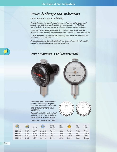
<strong>Brown</strong> & <strong>Sharpe</strong> <strong>Dial</strong> <strong>Indicators</strong><br />
Better Response - Better Re li abil i ty<br />
Unlimited application for set up and checking of turned, milled and ground<br />
parts; for tool setting gages, fixtures and in spec tion, etc. The AGD <strong>Dial</strong><br />
Indicator Series likely meets more re quire ments than any other indicators.<br />
Racks and bottom bearings are made from stainless steel. Rack teeth are<br />
ground to ensure ac cu ra cy, responsiveness and re li abil i ty that you can count on.<br />
All AGD In di ca tors are supplied with central lug back which can be rotated 90°<br />
for vertical or hor i zon tal use.<br />
Now available in easy-to-read satin black “Jet Console” face with high visibility<br />
orange hand or standard white face with black hand.<br />
Series 0 <strong>Indicators</strong> - 1-1/8" Diameter <strong>Dial</strong><br />
Combining precision with re li abil i ty,<br />
the small size and light weight of<br />
the Series 0 indicators make them<br />
ideal for mul ti di men sion al fixture<br />
ap pli ca tions.<br />
Fitted with central lug back and ball<br />
contact tip as standard. A flat back<br />
is also available as an ac ces so ry.<br />
Contact point thread is No. 10 BA.<br />
10<br />
5<br />
15<br />
-0+<br />
0.001 in.<br />
Type 71<br />
20<br />
5<br />
15<br />
10<br />
2<br />
3<br />
1<br />
4<br />
-0+<br />
0.0001 in.<br />
Type 73<br />
Travel Total <strong>Dial</strong> Hand<br />
Series per rev. Travel Color Color<br />
14.81000 81000 MW73 0.0001 in 0.01 in 0.05 in 0-5-0 White Black<br />
14.81001 81001 MB73 0.0001 in 0.01 in 0.05 in 0-5-0 Black Orange<br />
14.81002 81002 MW71 0.001 in 0.04 in 0.05 in 0-20-0 White Black<br />
14.81003 81003 MB71 0.001 in 0.04 in 0.05 in 0-20-0 Black Orange<br />
5<br />
1<br />
4<br />
2<br />
3
20<br />
30<br />
10<br />
40<br />
External Micrometers<br />
Mechanical <strong>Dial</strong> <strong>Indicators</strong><br />
External Micrometers<br />
AGD 1 <strong>Indicators</strong> — 1-11/16" Diameter <strong>Dial</strong><br />
The AGD 1 series dial indicators are supplied with revolution counter, tolerance<br />
pointers, central lug back and ball contact tip as stan dard.<br />
-0+<br />
Alternative flat and slide back are available as accessories.<br />
181<br />
50<br />
10<br />
40<br />
Travel Total <strong>Dial</strong> Hand<br />
Series per rev. Travel Color Color<br />
14.83004 88335 MW193 0.0001 in 0.01 in 0.05 in 0-5-0 White Black<br />
14.83005 88336 MB193 0.0001 in 0.01 in 0.05 in 0-5-0 Black Orange<br />
14.83006 88333 MW183 0.0005 in 0.05 in 0.25 in 0-25-0 White Black<br />
14.83007 88334 MB183 0.0005 in 0.05 in 0.25 in 0-25-0 Black Orange<br />
14.83008 88331 MW181 0.001 in 0.1 in 0.25 in 0-50-0 White Black<br />
14.83009 88332 MB181 0.001 in 0.1 in 0.25 in 0-50-0 Black Orange<br />
20<br />
30<br />
10<br />
15<br />
5<br />
20<br />
-0+<br />
183<br />
25<br />
5<br />
20<br />
10<br />
15<br />
2<br />
3<br />
1<br />
4<br />
-0+<br />
193<br />
5<br />
1<br />
4<br />
2<br />
3<br />
E-11
E-12<br />
14.82022<br />
Mechanical <strong>Dial</strong> <strong>Indicators</strong> External Micrometers<br />
AGD 2 <strong>Indicators</strong> — 2-1/4" Diameter <strong>Dial</strong><br />
AGD 2 - SHOCKPROOF MODELS<br />
The models MB211 and MW211 are supplied with a full shockproof<br />
mech a nism, which is ideal where the indicators may be subjected to sudden<br />
impacts to the rack.<br />
30<br />
10<br />
20<br />
540<br />
15<br />
10<br />
-0+<br />
210<br />
-0+<br />
50<br />
214<br />
20<br />
10<br />
40<br />
5<br />
15<br />
14.82023<br />
20<br />
30<br />
10<br />
80<br />
70<br />
40<br />
35<br />
90<br />
45<br />
60<br />
30<br />
0<br />
211SP 216<br />
0<br />
50<br />
217<br />
25<br />
10<br />
5<br />
40<br />
20<br />
20<br />
30<br />
10<br />
15<br />
14.81029<br />
w/special<br />
yellow dial<br />
10<br />
15<br />
3<br />
2<br />
5<br />
1<br />
20<br />
4<br />
-0+<br />
212SP<br />
240<br />
5<br />
5<br />
4<br />
10<br />
15<br />
-0+<br />
1<br />
20<br />
25<br />
2<br />
Travel Total <strong>Dial</strong> Hand<br />
Series per rev. Travel Color Color<br />
14.83020 88346 MW211SP 0.001 in 0.10 in 0.5 in 0-100 White Black<br />
14.83021 88347 MB211SP 0.001 in 0.10 in 0.5 in 0-100 Black Orange<br />
14.83014 88348 MW212SP 0.0005 in 0.05 in 0.5 in 0-25-0 White Black<br />
3<br />
The AGD 2 series of dial<br />
in di ca tors are the most<br />
popular indicators in the<br />
<strong>Brown</strong> & <strong>Sharpe</strong> range.<br />
All models are supplied<br />
with a rev o lu tion counter,<br />
tolerance pointers, central<br />
lug back and ball contact<br />
tip as standard.<br />
Alternative flat and slide<br />
backs are available as<br />
accessories.<br />
Travel Total <strong>Dial</strong> Hand<br />
Series per rev. Travel Color Color<br />
14.83018 88337 MW210 0.001 in 0.10 in .350 in 0-50-0 White Black<br />
14.83019 88338 MB210 0.001 in 0.10 in .350 in 0-50-0 Black Orange<br />
14.83012 88339 MW214 0.0005 in 0.04 in .350 in 0-20-0 White Black<br />
14.83013 88340 MB214 0.0005 in 0.04 in .350 in 0-20-0 Black Orange<br />
14.82022 26862 MW216 0.001 in 0.10 in 1.0 in 0-100 White Black<br />
14.82023 26863 MB216 0.001 in 0.10 in 1.0 in 0-100 Black Orange<br />
14.82028 26864 MW216 0.001 in 0.10 in 1.0 in 0-100† White Black<br />
14.82016 26860 MW217 0.0005 in 0.05 in 1.0 in 0-50 White Black<br />
14.82017 26861 MB217 0.0005 in 0.05 in 1.0 in 0-50 Black Orange<br />
14.82010 26858 MW240 0.0001 in 0.01 in 0.2 in 0-5-0 White Black<br />
14.82011 26859 MB240 0.0001 in 0.01 in 0.2 in 0-5-0 Black Orange<br />
14.81029 27058 MB216Y 0.001 in 0.10 in 1.0 in 0-100 Yellow Black<br />
† Counterclockwise dial for depth gages.
External Micrometers<br />
Mechanical <strong>Dial</strong> <strong>Indicators</strong><br />
External Micrometers<br />
AGD 3 <strong>Indicators</strong> — 3" Diameter <strong>Dial</strong><br />
The AGD 3 series gages have a large, clear dial and are easy to read at a<br />
distance. Fatigue is thereby min i mized. A tensator return spring gives a<br />
constant pressure through out the total travel of the gage.<br />
Both models are supplied with a revolution counter, central lug back, and ball<br />
contact tip as standard.<br />
80<br />
70<br />
90<br />
60<br />
0<br />
222A<br />
50<br />
10<br />
40<br />
20<br />
30<br />
Extremely valuable in the work shop,<br />
where many awk ward machining<br />
situations arise, the back plunger<br />
indicator has been designed to<br />
ensure that the face of the dial can<br />
be pre sent ed to the op er a tor. Note<br />
that the 1/4" O.D. holding rod can<br />
be un screwed from the indicator if<br />
required. All gages are supplied with<br />
ball contact tip.<br />
10<br />
15<br />
-0+ 5<br />
5 TYPE 91<br />
0.001 in.<br />
20<br />
25<br />
20<br />
14.83027 14.83026<br />
Travel Total <strong>Dial</strong> Hand<br />
Series per rev. Travel Color Color<br />
14.83026 88349 MW22A 0.001 in 0.10 in 2.0 in 0-100 White Black<br />
14.83027 88350 MB222A 0.001 in 0.10 in 2.0 in 0-100 Black Orange<br />
Back Plunger <strong>Indicators</strong> — 1-1/2" Diameter <strong>Dial</strong><br />
10<br />
15<br />
14.81025 14.81024<br />
Travel Total <strong>Dial</strong> Hand<br />
Series per rev. Travel Color Color<br />
14.81024 81024 MW91 0.001 in 0.05 in 0.14 in 0-25-0 White Black<br />
14.81025 81025 MB91 0.001 in 0.05 in 0.14 in 0-25-0 Black Orange<br />
E-13
E-14<br />
D<br />
Actual Size <strong>Dial</strong> Faces<br />
20<br />
30<br />
C<br />
10<br />
40<br />
Mechanical <strong>Dial</strong> <strong>Indicators</strong> External Micrometers<br />
AGD <strong>Dial</strong> Indicator Dimensions<br />
All <strong>Brown</strong> & <strong>Sharpe</strong> <strong>Dial</strong> <strong>Indicators</strong> conform to ANSI B89.1.10M specifications.<br />
1/4 in.<br />
0<br />
.001¨<br />
SHO CK PROO<br />
50<br />
B<br />
10<br />
40<br />
Range<br />
20<br />
30<br />
3/4 in.<br />
5/16 in.<br />
*Dimensions courtesy of The American Society Of Mechanical Engineers, ANSI SPEC. B89.1.10M.<br />
20<br />
30<br />
Dimension Reference<br />
F<br />
10<br />
40<br />
A<br />
Minimum distance<br />
from center of hole<br />
to nearest projection<br />
on back.<br />
0<br />
.001¨<br />
SHO CK PRO O F<br />
50<br />
10<br />
40<br />
1/4 in.<br />
Bezel Diameter A 1.812 2.250<br />
Center Line to Tip of Contact B 1.625 2.000<br />
Case Diameter C 1.608 2.031<br />
Stem Length D 0.572* 0.739*<br />
*Long Stem <strong>Indicators</strong> – “D” equals 3.000 inches.<br />
20<br />
30<br />
AGD Size (in)<br />
1 2<br />
No. 4-48<br />
thread<br />
0.375 in.<br />
diam.
External Micrometers<br />
Mechanical <strong>Dial</strong> <strong>Indicators</strong><br />
External Micrometers<br />
Quick Selection Table<br />
The Industry’s Most Popular <strong>Indicators</strong><br />
This quick selection table has been arranged to make it easier to locate the<br />
AGD <strong>Indicators</strong> that you demand most often. Each one is listed again among its<br />
designated group in the pages that follow.<br />
Regular Models<br />
D1-20141A 33638 1 .025 in .0001 in 1.75 0-5-0<br />
D1-20241A 33836 2 .025 in .0001 in 2.25 0-5-0<br />
D1-20126A 33611 1 .075 in .0005 in 1.75 0-15-0<br />
D1-20226A 33786 2 .075 in .0005 in 2.25 0-15-0<br />
D1-20111A 33557 1 .250 in .001 in 1.75 0-50-0<br />
D1-20211A 33705 2 .250 in .001 in 2.25 0-50-0<br />
Long-Range <strong>Indicators</strong><br />
D5-21221F 86002 2 1.00 in .0005 in 2.25 0-50<br />
1-Rev <strong>Indicators</strong><br />
D1-23226A 86006 2 .025 in .0005 in 2.25 0-10-0<br />
D1-23241A 34018 2 .008 in .0001 in 2.25 0-4-0<br />
Metric <strong>Indicators</strong><br />
AGD<br />
Group<br />
<strong>Dial</strong><br />
Dia.<br />
D1-20261A 33857 2 2.5mm 0.01 mm 2.25 0-50-0<br />
D1-20281A 33886 2 0.5mm 0.002 mm 2.25 0-10-0<br />
E-15
E-16<br />
Mechanical <strong>Dial</strong> <strong>Indicators</strong> External Micrometers<br />
Regular Models<br />
Conform to ANSI B89.1.10M Specifications.<br />
High performance, shockproof design.<br />
Hardened steel contact point.<br />
Vertical centered lug back.<br />
Balanced dial reading.<br />
Precision Bearings<br />
The sizes, materials, and finishes of pivots and bearings are the best possible<br />
choice for optimum Indicator performance and lowest cost of ownership.<br />
*For AGD Dimensions, see page E-15.<br />
AGD<br />
Group<br />
in in in<br />
D1-20111A 33557 1 .250 .100 .001<br />
D1-20211A 33705 2 .250 .100 .001<br />
D1-20126A 33611 1 .075 .030 .0005<br />
D1-20226A 33786 2 .075 .030 .0005<br />
D1-20141A 33638 1 .025 .010 .0001<br />
D1-20241A 33836 2 .025 .010 .0001<br />
✓<br />
Rotating dial<br />
with lock<br />
Full metal<br />
case housing<br />
and bevel<br />
Identification<br />
number<br />
Declaration of<br />
conformity<br />
Plastic box
✓<br />
Rotating dial<br />
with lock<br />
Full metal<br />
case housing<br />
and bevel<br />
Identification<br />
number<br />
Declaration of<br />
conformity<br />
Plastic box<br />
20<br />
30<br />
10<br />
40<br />
0<br />
.001"<br />
SHOCKPROOF<br />
0 1<br />
2 2<br />
3 3<br />
4 5 4<br />
D1-29111<br />
1<br />
50<br />
External Micrometers<br />
Mechanical <strong>Dial</strong> <strong>Indicators</strong><br />
External Micrometers<br />
10<br />
40<br />
20<br />
30<br />
Intermediate Range <strong>Indicators</strong><br />
Conform to ANSI B89.1.10M Specifications.<br />
2<br />
3<br />
0<br />
.0005"<br />
SHOCKPROOF<br />
D1-29128<br />
20<br />
High performance, shockproof design.<br />
Hardened steel contact point.<br />
Vertical centered lug back.<br />
Balanced dial reading.<br />
Revolution counter.<br />
Tolerance pointers.<br />
5<br />
3<br />
4<br />
157<br />
10 5<br />
6<br />
4<br />
2<br />
3<br />
AGD<br />
Group<br />
0<br />
.0001"<br />
SHOCKPROOF<br />
D1-29141<br />
5<br />
202<br />
303<br />
D2-29111E 34052 1 .312 in .100 in .001 in<br />
D2-29211E 34117 2 .312 in .100 in .001 in<br />
D2-29128E 34080 1 .312 in .040 in .0005 in<br />
D2-29228E 34157 2 .312 in .040 in .0005 in<br />
D2-29141E 34088 1 .100 in .010 in .0001 in<br />
D2-29241E 34169 2 .100 in .010 in .0001 in<br />
D2-29161E 34097 1 8.0 mm 1.0 mm .01 mm<br />
D2-29261E 34181 2 8.0 mm 1.0 mm .01 mm<br />
D2-29181E 34112 1 1.9 mm 0.2 mm .002 mm<br />
D2-29281E 34192 2 1.9 mm 0.2 mm .002 mm<br />
1<br />
4<br />
10<br />
0 9<br />
2 8<br />
3 7<br />
4 5 6<br />
1<br />
40<br />
0<br />
0.01mm<br />
SHOCKPROOF<br />
D2-29161<br />
*The periphery of dial designs are identical to Regular Model dials.<br />
*For AGD Dimensions, see page E-15.<br />
50<br />
Intermediate Range<br />
<strong>Indicators</strong> are a standard<br />
modification of the Regular<br />
AGD <strong>Indicators</strong>. Designed<br />
to meet the occasional<br />
requirement for extra<br />
range, they are supplied<br />
with a balanced dial and<br />
a revolution counter for<br />
comparative-type reading<br />
applications.<br />
10<br />
40<br />
3<br />
4 20<br />
5<br />
6 30<br />
2<br />
1<br />
0 9<br />
2 8<br />
3 7<br />
4 5 6<br />
1<br />
7<br />
0<br />
0.002mm<br />
SHOCKPROOF<br />
D2-29181<br />
8 9 10<br />
1<br />
9<br />
2<br />
8<br />
3<br />
7<br />
4<br />
6<br />
5<br />
E-17
E-18<br />
20<br />
30<br />
10<br />
Mechanical <strong>Dial</strong> <strong>Indicators</strong> External Micrometers<br />
1-REV <strong>Indicators</strong><br />
Conform to ANSI B89.1.10M Specifications.<br />
0<br />
REV<br />
SHOCKPROOF<br />
D1-23211<br />
.001"<br />
Exclusive Shockproof Design.<br />
Precision Bearings.<br />
The 1-Rev always keeps the Indicator Hand within one revolution.<br />
Does not restrict spindle travel.<br />
Does not affect magnification.<br />
Does not damage the movement.<br />
Provides accurate, instant readings.<br />
10<br />
40 40<br />
20<br />
30<br />
10<br />
*For AGD Dimensions, see page E-15.<br />
AGD<br />
Group<br />
0<br />
REV<br />
SHOCKPROOF<br />
10<br />
5<br />
20<br />
40<br />
D1-23161<br />
30<br />
10<br />
40<br />
0.01mm<br />
D1-23171<br />
0.005mm<br />
Spindle<br />
Travel<br />
5 2<br />
1 0<br />
REV<br />
1<br />
2<br />
3<br />
10<br />
SHOCKPROOF 4<br />
5<br />
15<br />
6<br />
20 8<br />
D1-23181<br />
0.002mm<br />
9 9<br />
8<br />
7<br />
D1-23111A 86362 1 .080 in .250 in .001 in<br />
D1-23211A 33986 2 .080 in .250 in .001 in<br />
D1-23126A 86366 1 .025 in .075 in .0005 in<br />
D1-23226A 86006 2 .025 in .075 in .0005 in<br />
D1-23141A 86368 1 .008in .025 in .0001 in<br />
D1-23241A 34018 2 .008 in .025 in .0001 in<br />
D1-23161A 86369 1 2.5 mm 2.50 mm .01 mm<br />
D1-23261A 34027 2 2.5 mm 2.50 mm .01 mm<br />
D1-23171A 33974 1 1.25 mm 1.25 mm .005 mm<br />
D1-23271A 34037 2 1.25 mm 1.25 mm .005 mm<br />
D1-23181A 33979 1 .5 mm 0.50 mm .002 mm<br />
D1-23281A 34047 2 .5 mm 0.50 mm .002 mm<br />
5<br />
0<br />
0<br />
REV<br />
SHOCKPROOF<br />
The 1-Rev cannot be a full<br />
revolution off because the<br />
Indicator only makes one<br />
revolution.<br />
Shockproof Mechanism<br />
Available in all AGD sizes<br />
and in inch or metric.<br />
Metric dials are yellow for<br />
easy identification.<br />
Dead Zone<br />
✓<br />
Rotating dial<br />
with lock<br />
Full metal<br />
case housing<br />
and bevel<br />
Identification<br />
number<br />
Declaration of<br />
conformity<br />
Plastic box
✓<br />
Rotating dial<br />
with lock<br />
Full metal<br />
case housing<br />
and bevel<br />
Identification<br />
number<br />
Declaration of<br />
conformity<br />
Plastic box<br />
External Micrometers<br />
Mechanical <strong>Dial</strong> <strong>Indicators</strong><br />
External Micrometers<br />
5" Long Stem <strong>Indicators</strong><br />
Conform to ANSI B89.1.10M Specifications.<br />
When a surface is difficult to access, a Long Stem Indicator can be used to<br />
reach it without losing measuring accuracy and without great expense. Stem<br />
lengths are 5" long.<br />
High performance, shockproof design.<br />
Hardened steel contact point.<br />
Vertical centered lug back.<br />
Balanced dial reading.<br />
Revolution counter.<br />
Tolerance pointers.<br />
*For AGD Dimensions, see page E-15.<br />
AGD<br />
Group<br />
D4-20226A 34400 2 .075 in .030 in .0005 in<br />
D4-20261A 34417 2 2.5 mm 1.0 mm .01 mm<br />
E-19
E-20<br />
Mechanical <strong>Dial</strong> <strong>Indicators</strong> External Micrometers<br />
Metric <strong>Indicators</strong> – Regular Models<br />
High performance, shockproof design.<br />
Hardened steel contact point.<br />
Vertical centered lug back.<br />
Balanced dial reading.<br />
AGD<br />
Group<br />
mm mm mm<br />
D1-20161A 33653 1 2.5 1.0 .01<br />
D1-20261A 33857 2 2.5 1.0 .01<br />
D1-20171A 33670 1 1.25 0.5 .005<br />
D1-20271A 33873 2 1.25 0.5 .005<br />
D1-20181A 33686 1 0.5 0.2 .002<br />
D1-20281A 33886 2 0.5 0.2 .002<br />
✓<br />
Rotating dial<br />
with lock<br />
Full metal<br />
case housing<br />
and bevel<br />
Identification<br />
number<br />
Declaration of<br />
conformity<br />
Plastic box
✓<br />
Rotating dial<br />
with lock<br />
Full metal<br />
case housing<br />
and bevel<br />
Identification<br />
number<br />
Declaration of<br />
conformity<br />
Plastic box<br />
External Micrometers<br />
Mechanical <strong>Dial</strong> <strong>Indicators</strong><br />
External Micrometers<br />
Long Range <strong>Indicators</strong><br />
Continuous and Balanced <strong>Dial</strong>s.<br />
Revolution Counter.<br />
Precision Bearings.<br />
Long-Range Lifting Lever<br />
Catalog No. 599-8400-279<br />
AGD<br />
Group<br />
*For AGD Dimensions, see page E-15.<br />
D5-21221F 86002 2 1.000 in .050 in .0005 in<br />
D5-21201F 34434 2 30 mm 1 mm .01 mm<br />
E-21
E-22<br />
Mechanical <strong>Dial</strong> <strong>Indicators</strong> External Micrometers<br />
IP54 Indicator<br />
IP54 – Waterproof protection (Norm IEC 60529)<br />
Fully protected against the penetration of liquid or solid contaminants. Dust,<br />
particles of metal, spraying water or oil are prevented from entering the indicator.<br />
Corrosion resistant.<br />
High performance, shockproof design.<br />
Hardened steel contact point.<br />
Vertical centered lug back.<br />
Balanced dial reading.<br />
Revolution counter.<br />
Tolerance pointers.<br />
In a shop environment, Precision <strong>Dial</strong> Gages are in constant contact with oil,<br />
water mist and dust. Hermetically sealed IP54 waterproof gages from <strong>Brown</strong> &<br />
<strong>Sharpe</strong> are specifically designed to withstand these conditions.<br />
Features:<br />
A flexible rubber bellows is fitted where the spindle enters the stem.<br />
The upper end of the measuring spindle is sealed by a safety cap and an<br />
“O” ring.<br />
A new design of the external metal ring and its assembly produces a perfect<br />
seal. Its special features include “O” rings, flat glasses and a screwed on<br />
brass ring. An additional “O” ring is placed between the rotating outer ring<br />
and the indicator’s metal housing.<br />
The back plate is fitted to prevent foreign matter from entering.<br />
<strong>Dial</strong><br />
Color<br />
D2-29111F-W 28629 .001 in .100 in .200 in 0-50-0 White<br />
D2-29228F-W 28630 .0005 in .050 in .400 in 0-25-0 White<br />
D2-29161F-W 28631 0.01 mm 0.5 mm 5 mm 0-50 Yellow<br />
D2-29261F-W 28632 0.01 mm 1 mm 10 mm 0-100 Yellow
External Micrometers<br />
Mechanical <strong>Dial</strong> <strong>Indicators</strong><br />
External Micrometers<br />
90˚ Models<br />
Precision Bearings.<br />
Metric <strong>Indicators</strong> are supplied with yellow tinted faces.<br />
8 mm stem supplied with .375" bushing.<br />
Revolution counter.<br />
Tolerance pointer.<br />
.375" bushing<br />
35.60101<br />
AGD<br />
Group<br />
D9-20111E 34479 1 .200 in .100 in .001 in<br />
D9-20221E 34526 2 .125 in .050 in .0005 in<br />
D9-20161E 34507 1 2.5 mm 1.0 mm .01 mm<br />
D9-20261E 34552 2 2.5 mm 1.0 mm .01 mm<br />
E-23
E-24<br />
Regular<br />
Furnished on all in di ca tors unless otherwise<br />
specified.<br />
Mushroom<br />
External Micrometers<br />
Electronic <strong>Indicators</strong><br />
Mechnical <strong>Dial</strong> <strong>Indicators</strong><br />
AGD <strong>Dial</strong> Indicator Contacts<br />
Material in<br />
D0-80001 33460 Steel 1/8<br />
D0-80104 33474 Steel 1/4<br />
D0-03024 33430 Steel 3/8<br />
D0-03032 33433 Steel 1/2<br />
D0-03040 33436 Steel 5/8<br />
D0-03048 33438 Steel 3/4<br />
D0-03056 33439 Steel 7/8<br />
D0-03100 33447 Steel 1<br />
D0-03132 33452 Steel 1-1/2<br />
D0-03140 33453 Steel 1-5/8<br />
D0-03148 33454 Steel 1-3/4<br />
D0-03156 33455 Steel 1-7/8<br />
D0-03200 33456 Steel 2<br />
D0-03208 33457 Steel 2-1/8<br />
D0-03216 33458 Steel 2-1/4<br />
D0-03224 33459 Steel 2-3/8<br />
D0-03240 33462 Steel 2-5/8<br />
D0-03248 33463 Steel 2-3/4<br />
D0-03256 33467 Steel 2-7/8<br />
D0-03263 33468 Steel 3<br />
D0-03308 33469 Steel 3-1/8<br />
D0-03316 33470 Steel 3-1/4<br />
D0-03366 33475 Carbide 1/4<br />
D0-03250 33464 Diamond 1/4<br />
Material in<br />
D0-03405 33480 Steel 3/32<br />
D0-80109 33477 Steel 1/8<br />
D0-03466 33481 Carbide 1/8<br />
Flat<br />
Material in<br />
D0-80101 33476 Steel 5/32<br />
D0-03364 33473 Steel 1/4<br />
D0-03013 33420 Steel 3/8<br />
D0-03014 33421 Steel 1/2<br />
D0-03015 33422 Steel 5/8<br />
D0-03016 33423 Steel 3/4<br />
D0-03017 33424 Steel 7/8<br />
D0-03018 33425 Steel 1<br />
D0-03363 33472 Carbide 1/4<br />
Extension<br />
Material in<br />
D0-80102 33431 Steel 7/16<br />
D0-03058 33440 Steel 7/8<br />
D0-70160 33539 Steel 1<br />
D0-03123 33450 Steel 1-3/8<br />
Large Wide Face<br />
Material in<br />
D0-03403 33478 Steel 1/8<br />
Presser Foot<br />
Material in<br />
D0-80103 33543 Steel 7/16<br />
Needle Point<br />
Material in<br />
D0-80007 33545 Steel 1/2<br />
D0-80007 33544 Steel 5/8<br />
D0-73517A 33547 Carbide 1/2<br />
D0-73517 33546 Carbide 5/8<br />
Taper<br />
Material in<br />
D0-80005 33426 Steel 7/16<br />
D0-80010 33427 Steel 1<br />
D0-03021 33428 Steel 1-7/16<br />
D0-03022 33429 Steel 2<br />
Shock Absorbing<br />
Material in<br />
D0-80105 33471 Steel 5/8
Measuring insert with offset (A)<br />
contact point. Lock nut for radial<br />
alignment.<br />
35.60063 28651 Steel 12<br />
Measuring inserts with blade-shaped<br />
measuring faces. Lock nut for radial<br />
alignment.<br />
35.60024 28655 Steel 0.3<br />
35.60025 28656 Carbide 0.3<br />
5 6,5<br />
3,3<br />
1<br />
0,5<br />
Measuring insert with off-center, narrow<br />
measuring face. Lock nut for radial<br />
alignment.<br />
16<br />
35.10602 28662 Carbide 0.5<br />
5<br />
Amm<br />
Bmm<br />
Bmm<br />
Mechnical <strong>Dial</strong> <strong>Indicators</strong><br />
Contact Points with M2.5 Threads<br />
Measuring insert with needle contact<br />
point.<br />
35.60030 28652 Steel<br />
Measuring inserts with blade-shaped<br />
measuring faces, in steel. Lock nut for<br />
radial alignment.<br />
L<br />
mm<br />
35.60031 28657 5 0.2<br />
35.60032 28658 10 0.2<br />
35.60033 28659 15 0.2<br />
35.60034 28660 20 0.2<br />
ø4<br />
2,5<br />
0,5<br />
3,0<br />
2,0<br />
1.6<br />
Measuring insert with adjustable narrow<br />
measuring face (parallelism). Lock nut<br />
for radial alignment.<br />
35.10702 28663 Carbide 0.5<br />
Bmm<br />
Measuring insert with a flat, adjustable<br />
measuring face (parallelism). Lock nut<br />
for radial alignment.<br />
35.10902 28668 Carbide 2.5<br />
8<br />
2,3<br />
16<br />
ø7,5<br />
B<br />
mm<br />
mm<br />
0,003<br />
6<br />
1,6<br />
7,5<br />
Measuring inserts with ball-bearing<br />
rollers. Lock nut for radial alignment.<br />
35.60010 28653 Steel<br />
Shape<br />
Cylindrical<br />
35.60011 28654 Steel ball-shaped<br />
3,3<br />
ø2<br />
2,5<br />
Measuring insert with a cylindrical<br />
measuring face. Lock nut for radial<br />
alignment.<br />
35.10502 28661 Carbide<br />
7<br />
øD<br />
Measuring inserts with a flat measuring face.<br />
13<br />
35.10801 28664 Steel 2.5<br />
35.10802 28665 Carbide 2.5<br />
35.60022 28666 Steel 3.4<br />
35.60023 28667 Carbide 3.4<br />
DO-69998 28650<br />
6<br />
6<br />
ø4<br />
mm<br />
E-25
E-26<br />
Flat<br />
External Micrometers<br />
Electronic <strong>Indicators</strong><br />
Mechnical <strong>Dial</strong> <strong>Indicators</strong><br />
AGD <strong>Dial</strong> Indicator Backs<br />
for Prior Design<br />
(<strong>Indicators</strong> purchased before 01/2002)<br />
A.G.D. Mil. Spec. Lug<br />
Furnished on all dial indicators unless<br />
otherwise specified.<br />
A.G.D. Mil. Spec. Post<br />
LC<br />
AGD<br />
Group<br />
D0-29002 33497 1<br />
D0-29202 33507 2<br />
AGD<br />
Group<br />
D0-29021 33499 1<br />
D0-29221 33509 2<br />
AGD<br />
Group<br />
D0-29069 33504 1<br />
D0-29269 33515 2<br />
.875 to Lc<br />
Spindle<br />
Dovetail Bracket<br />
.562<br />
1.00<br />
D0-29253 33510<br />
(fits both sizes)<br />
A.G.D. Mil. Spec. Screw<br />
1.50<br />
.635<br />
.938<br />
1.50<br />
AGD<br />
Group<br />
D0-29068 33503 1<br />
D0-29268 33514 2<br />
Style H<br />
A.G.D. Mil. Spec. Adjustable<br />
AGD<br />
Group<br />
D0-29003 33498 1<br />
D0-29203 33508 2<br />
Style K Style M Style N<br />
A.G.D. Mil. Spec. Offset Lug<br />
LC<br />
AGD<br />
Group<br />
D0-29001 33496 1<br />
D0-29201 33506 2<br />
Style P Style R Style T<br />
Dovetail Rack<br />
AGD<br />
Group<br />
D0-29056 33500 1<br />
D0-29256 33511 2
To order an indicator<br />
with a specific back,<br />
place the style letter<br />
designation at the end<br />
of the indictator part<br />
number. For example,<br />
a D1-20241A indicator<br />
(shown on page E-17)<br />
will be shipped with a<br />
flat back if the style<br />
letter K is added to the<br />
end of the part number,<br />
as D1-20241AK.<br />
Mechnical <strong>Dial</strong> <strong>Indicators</strong><br />
AGD <strong>Dial</strong> Indicator Backs<br />
for Current Design<br />
(<strong>Indicators</strong> purchased during or after 01/2002)<br />
A.G.D. Mil. Spec. Lug<br />
Furnished on all dial indicators unless<br />
otherwise specified.<br />
AGD<br />
Group<br />
D0-29002-1 28669 1<br />
D0-29202-1 28670 2<br />
Flat<br />
Style K<br />
D0-29021-1 28673 1<br />
D0-29221-1 28674 2<br />
Style P<br />
A.G.D. Mil. Spec. Post<br />
AGD<br />
Group<br />
AGD<br />
Group<br />
D0-29069-1 28675 1<br />
D0-29269-1 28676 2<br />
Style H<br />
A.G.D. Mil. Spec. Adjustable<br />
Style N<br />
A.G.D. Mil. Spec. Offset Lug<br />
AGD<br />
Group<br />
D0-29001-1 28671 1<br />
D0-29201-1 28672 2<br />
A.G.D. Mil. Spec. Screw<br />
D0-29068-1 28677 1<br />
D0-29268-1 28678 2<br />
LC<br />
Style R<br />
AGD<br />
Group<br />
D0-29203 -1 2<br />
AGD<br />
Group<br />
E-27
E-28<br />
External Micrometers<br />
Electronic <strong>Indicators</strong><br />
Mechnical <strong>Dial</strong> <strong>Indicators</strong><br />
Indicator <strong>Dial</strong> Options<br />
Solid <strong>Dial</strong><br />
Continuous dial reading clockwise or coun ter clockwise, or balanced dial with<br />
“plus" or “minus" signs.<br />
20<br />
30<br />
40<br />
0<br />
10 .001¨<br />
50<br />
10<br />
40<br />
20<br />
30<br />
Format A<br />
Balanced Numbering<br />
(Plus on right, minus on left)<br />
Double <strong>Dial</strong>s - Revolution Counting Hands<br />
Con tin u ous dials reading clock wise or coun ter clock wise, or balanced dials<br />
without “plus” or “minus” signs, complete with revolution counting hands.<br />
20<br />
30<br />
40<br />
0<br />
10 .001¨<br />
50<br />
10<br />
1 0 12<br />
2<br />
3 3<br />
4 5 4<br />
40<br />
Format E<br />
Balanced Numbering<br />
(Plus and minus omitted)<br />
20<br />
30<br />
80<br />
70<br />
60<br />
0<br />
90 .001¨<br />
MADE IN U.S.A.<br />
50<br />
10<br />
1 0 98<br />
2<br />
3 7<br />
4 5 6<br />
40<br />
Format F<br />
Continuous Clockwise<br />
Numbering<br />
20<br />
30
Collet Clamp<br />
B&S 599-8941 45054<br />
B&S 599-8940 (9/16-18 Thrd.) 45053<br />
Moisture Seal*<br />
D0-69984 33538<br />
Mechnical <strong>Dial</strong> <strong>Indicators</strong><br />
AGD <strong>Dial</strong> Indicator Accessories<br />
Bell Crank*<br />
D0-48255 33521 12<br />
Hole Attachments*<br />
.81<br />
1.125"<br />
1.81<br />
2.06<br />
1.125"<br />
3.81<br />
D0-69974 33534 .25<br />
D0-69975 33535 .50<br />
* Fits all .375 AGD Mil. Spec. stem diameters<br />
in<br />
in<br />
.87<br />
.87<br />
E-29
E-30<br />
External Micrometers<br />
Electronic <strong>Indicators</strong><br />
Mechnical <strong>Dial</strong> <strong>Indicators</strong><br />
AGD <strong>Dial</strong> Indicator Accessories (cont.)<br />
Long-Range Lifting Lever<br />
in<br />
D0-48279 33522 0 - 1<br />
Used primarily on D5-21211 to provide<br />
for full spindle re trac tion.<br />
Holding Rod<br />
For 90° <strong>Indicators</strong><br />
D0-95020 33548 0.31<br />
D0-95030 33549 0.25<br />
D0-95050 33550 0.38<br />
Split Bushing*<br />
.50<br />
2.50<br />
.50<br />
D0-69976 33536<br />
All dimensions are in inches unless otherwise specified.<br />
* Fits all .375 AGD Mil. Spec. stem diameters<br />
in
✓<br />
Wood case<br />
Mechnical <strong>Dial</strong> <strong>Indicators</strong><br />
AGD <strong>Dial</strong> Indicator Accessories<br />
Contact Point Set<br />
Eliminates trouble in measuring hard-to-get-at places and en ables you to make<br />
complete use of your <strong>Dial</strong> Indicator. The set includes 22 points in various<br />
shapes and sizes.<br />
The set is supplied with a fitted case. Points have AGD Stan dard #4-48 threads<br />
and are protected against corrosion.<br />
599-7886 44958<br />
Blanks<br />
Material in<br />
D0-03007 33414 Steel 1/2<br />
D0-03008 33415 Steel 3/4<br />
D0-03009 33416 Steel 1<br />
D0-03010 33417 Steel 1-1/2<br />
D0-03011 33418 Steel 2<br />
D0-03012 33419 Steel 2-1/2<br />
E-31