magazinE - dSPACE
magazinE - dSPACE
magazinE - dSPACE

Create successful ePaper yourself
Turn your PDF publications into a flip-book with our unique Google optimized e-Paper software.
with flywheel mass test benches.<br />
This is done by means of a device<br />
that emulates loads.<br />
On the test bench, the motors of the<br />
actuators form the interface to the<br />
simulated braking actuators. Highly<br />
dynamic load equipment consisting<br />
of servo drives is applied to the<br />
motors to ensure dynamic simulation<br />
of the real loads that would occur<br />
in the vehicle. The electrical and<br />
mechanical components are<br />
designed so that prototypes can be<br />
installed and assembled flexibly in<br />
various test configurations.<br />
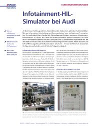
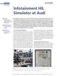
The complete communication<br />
network of the electrical braking<br />
system, with the pedal unit and the<br />
additional function of the electronic<br />
parking brake, is represented in<br />
hardware form in the test system.<br />
In addition to CAN communication<br />
with the braking system’s central<br />
ECU, a flexible FlexRay communication<br />
architecture was also set up.<br />
This enables all four wheel units of<br />
the brakebywire system to be<br />
simulated as required. Switching<br />
between the wheel units is performed<br />
by software, right through<br />
to the model.<br />
The mechanical, electrical, and communication<br />
variables of the system<br />
network are captured at various<br />
measurement points and archived in<br />
the automation system for subsequent<br />
evaluation.<br />
Load representation at the actuator.<br />
The core of the test bench automation<br />
system (AT) is a DS1005 PPC<br />
Board networked with several<br />
<strong>dSPACE</strong> I/O boards. The test bench<br />
therefore has a complex FlexRay<br />
network with a total of two independent<br />
networks in addition to<br />
CAN communication with the ECUs.<br />
To connect the test system to the<br />
FlexRay bus, the FlexRay Configuration<br />
Tool from <strong>dSPACE</strong> is used with a<br />
network description in a FIBEX (field<br />
bus exchange format) file.<br />
The vehicle model is calculated on<br />
an additional DS1005 that is<br />
“ The seamlessly integrated development<br />
environment from <strong>dSPACE</strong> lets us carry out<br />
projects efficiently. The help given by <strong>dSPACE</strong><br />
Support was exemplary.“<br />
Franz Hangl, IABG<br />
connected to the test bench automation<br />
system in real time via<br />
<strong>dSPACE</strong> Gigalink (a highspeed<br />
optical connection). The processes<br />
on the automation platform and<br />
the model platform communicate at<br />
intervals of 1 ms. On the software<br />
HIL Real-Time Platform<br />
whl spd<br />
Virtual Vehicle Environment, ...<br />
Actuator Model<br />
T_load F_caliper position actuator 1<br />
I/O<br />
M<br />
T_Load<br />
Shaft<br />
M<br />
load motor 1<br />
actuator 1<br />
M<br />
T_Load<br />
Shaft<br />
M<br />
load motor 2 actuator 2<br />
Sensor<br />
side, the HIL platform provides integrated<br />
vehicle dynamics behavior<br />
based on the <strong>dSPACE</strong> Automotive<br />
Simulation Models (ASM). The major<br />
components of this simulation environment<br />
are models for the vehicle,<br />
driver, and environment, the associated<br />
model control, and model<br />
parameterization functions. One<br />
point particularly worth noting is<br />
that integrated simulation is performed<br />
for any system components<br />
that are not installed as real parts.<br />
Because the model structure is open<br />
down to the Simulink block level, it<br />
did not take long to make optimum<br />
modifications to the model components<br />
of the ASM Vehicle Dynamics<br />
Simulation Package.<br />
The automation software builds on<br />
the MATLAB ® /Simulink ® /Stateflow ®<br />
development environment and the<br />
ControlDesk experiment software<br />
from <strong>dSPACE</strong>. Some of the functions<br />
that have to be executed on the AT<br />
realtime system are:<br />
n Eventdiscrete sequence control<br />
for the test system control and<br />
the implemented single tests<br />
n Communication with the ECUs<br />
via FlexRay and CAN protocols<br />
n Communication with the HIL<br />
realtime board via Gigalink<br />
interface<br />
µ_disc brake torque<br />
solenoid for failsafe mechanism<br />
position actuator 2 position<br />
solenoid<br />
forces<br />
whl spd<br />
Wheel Control Unit<br />
of Actuators<br />
pAGe 17