magazinE - dSPACE
magazinE - dSPACE
magazinE - dSPACE

You also want an ePaper? Increase the reach of your titles
YUMPU automatically turns print PDFs into web optimized ePapers that Google loves.
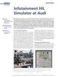
pAGe 16 BRAKe-BY-WIRe SYSTeMS<br />
This hardwareintheloop (HIL) test<br />
system has proven to be an efficient<br />
development and testing tool<br />
within the development process.<br />
Its main tasks are putting the system<br />
network into operation, function<br />
verification, failsafe trials and<br />
investigating the energy management<br />
functions of the braking<br />
system. HIL test procedures have<br />
numerous advantages over test<br />
drives in laboratory vehicles – reproducibility,<br />
efficiency, cost efficiency,<br />
etc., – and all these are fully utilized.<br />
Development approach to<br />
Complete Brake-by-Wire Systems<br />
The completely new braking technology<br />
in the electronic braking system<br />
utilizes a principle that is as simple as<br />
it is effective. Based on conventional<br />
friction braking, it involves no<br />
hydraulics whatsoever: the actuators<br />
are operated entirely by electronically<br />
controlled electric drives. Each wheel<br />
has its own control unit. When the<br />
car driver presses the braking pedal,<br />
an electronic signal is sent to the<br />
wheel brake. Sophisticated sensors<br />
and software optimally adjust the<br />
braking power on the wheel to a<br />
wide variety of road conditions.<br />
During braking, the friction arising<br />
between the brake pad and the brake<br />
disk generates torque on the pad.<br />
This is fed back into clamping force<br />
generation. Thus, much of the brake<br />
caliper’s clamping energy is obtained<br />
from the vehicle’s kinetic energy,<br />
so it does not have to be mainly fed<br />
in externally as electrical power.<br />
The main technical point is that this<br />
braking principle consumes less<br />
energy than other systems. For the<br />
first time ever, very high clamping<br />
energies and excellent control<br />
dynamics can be achieved with the<br />
12V vehicle electrical systems<br />
currently in widespread use.<br />
The system also has an integrated<br />
parking brake function.<br />
HiL Test System: integral Part of<br />
the Development Process for the<br />
Electrical Braking System<br />
The HIL test system was designed to<br />
verify the networked system functions<br />
and system communication<br />
and to perform further investigations<br />
during the development process.<br />
It acts as a system test bench for<br />
putting the system network into<br />
operation and for testing system<br />
functionality. Other purposes include<br />
investigating and optimizing basic<br />
functions and energy management<br />
in the backup level of the braking<br />
system, and testing how the braking<br />
system interacts with the simulated<br />
vehicle electrical system.<br />
To create a complete HIL test system,<br />
it is supplemented by an applicationspecific,<br />
adapted, extended simulation<br />
environment based on the<br />
<strong>dSPACE</strong> Automotive Simulation<br />
Models (ASM). This simulates the<br />
vehicle dynamics’ behavior in a virtual<br />
vehicle in real time. The physical<br />
vehicle variables and mean value<br />
variables calculated for the braking<br />
system are used to control the<br />
dynamic restbus simulation and the<br />
test system actuators.<br />
The applications focus on putting<br />
the system into operation, testing<br />
communication between system<br />
components, and studying error<br />
behavior when individual components<br />
fail. The integrated vehicle dynamics<br />
simulation makes it possible to<br />
systematically test different driving<br />
maneuvers including specific vehicle<br />
dynamics situations. The results are<br />
used to validate the system network<br />
and its functional properties, taking<br />
into account the effects of failures<br />
on driving behavior.<br />
Set-up and System architecture<br />
Since the generation of clamping<br />
forces depends on (load) torques<br />
being transmitted via the brake<br />
disks, the task at actuator level is to<br />
implement a suitable load for the test<br />
bench under costefficiency constraints,<br />
i.e., to avoid using actuators<br />
operated via a real gyrating mass like<br />
Set-up of the HIL test bench.