magazinE - dSPACE
magazinE - dSPACE
magazinE - dSPACE

You also want an ePaper? Increase the reach of your titles
YUMPU automatically turns print PDFs into web optimized ePapers that Google loves.
pAGe 10 AUTOSAR FUNCTION DeveLOpMeNT<br />
developed by the classic method.<br />
This means that AUTOSAR technology<br />
can be introduced step by step.<br />
modeling at Behavior<br />
and architecture Level<br />
With AUTOSAR, modeling is<br />
performed at two levels: Beside the<br />
behavior level, where the behavior<br />
of the functions is modeled, there is<br />
an architecture level where the<br />
interfaces of the SWCs and their<br />
connections have to be formally<br />
described.<br />
In a topdown strategy, when new<br />
vehicle functions are developed it is<br />
useful to first subdivide their<br />
functionality into several SWCs and<br />
then to define their interfaces at<br />
architecture level (fig. 4). Then the<br />
behavior of the resulting SWCs is<br />
modeled.<br />
For previously existing function<br />
models, a bottomup procedure can<br />
be used to generate the SWC<br />
descriptions from the model interfaces.<br />
The resulting SWCs are then<br />
connected with one another at<br />
architecture level.<br />
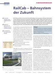
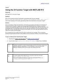
ECU Integration<br />
SWC 1 SWC 2 SWC n<br />
AUTOSAR RTE<br />
Standard core and<br />
tier 1 parts<br />
Stepwise introduction means that it<br />
is not possible to produce a complete<br />
topdown design of a whole<br />
vehicle. It also means that at the<br />
level of single ECUs, not all functions<br />
are initially available as models. A<br />
meetinthemiddle strategy has<br />
therefore proved useful, with the<br />
following steps being performed for<br />
each ECU:<br />
n The SWC descriptions are derived<br />
from existing behavior models.<br />
n For new vehicle functions, the<br />
interfaces are first defined<br />
at architecture level via SWCs.<br />
n Sensor/actuator SWCs are<br />
generated automatically according<br />
to fixed rules.<br />
The resulting SWCs are then collected<br />
together in a composition at architecture<br />
level and networked with<br />
one another. The remaining unconnected<br />
ports are led through to the<br />
outside, which turns them into<br />
ports in the composition. The ports<br />
now represent the communication<br />
interface of the ECU. Data elements<br />
referenced via the ports can be<br />
mapped to the signals specified for<br />
AUTOSAR Services<br />
the ECU by the communication<br />
matrix. This makes it possible to<br />
create the SWC structure of an ECU<br />
at a reasonable cost.<br />
The next section explains these<br />
activities in greater detail.<br />
Defining the aUTOSaR interfaces<br />
The basis for developing software<br />
components is a shared database or<br />
common object pool (COP) of<br />
interface and data type definitions<br />
that the SWC developers can use<br />
when defining SWC ports. The pool<br />
was derived from the signal<br />
definitions in the communication<br />
matrix and must be constantly<br />
reconciled with this (fig. 8).<br />
The derivation rules state that one<br />
interface with a data element must<br />
be generated for each communication<br />
matrix signal. This facilitates the<br />
transition from the current communication<br />
matrix signal world to the<br />
AUTOSAR world, since the same<br />
names are used and the corresponding<br />
interfaces are therefore easy to<br />
find. AUTOSAR’s structural options<br />
for collecting several data elements<br />
together in one interface are used<br />
Fig. 3: In stepwise AUTOSAR introduction,<br />
first the application software (SWCs) and<br />
the middleware (RTE) will be developed<br />
in compliance with AUTOSAR. The basic<br />
software will still consist of the Daimler<br />
Standard Core, extended by selected<br />
AUTOSAR software services.