Real Time Implementation of a Multiuser Detection Enabled
Real Time Implementation of a Multiuser Detection Enabled
Real Time Implementation of a Multiuser Detection Enabled

Create successful ePaper yourself
Turn your PDF publications into a flip-book with our unique Google optimized e-Paper software.
REAL TIME IMPLEMENTATION OF A MULTIUSER DETECTION<br />
ENABLED AD-HOC NETWORK<br />
978-1-4244-2677-5/08/$25.00 ©2008 IEEE<br />
John A. Tranquilli, Joseph A. Farkas, Joshua D. Niedzwiecki<br />
BAE SYSTEMS Advanced Systems & Technology, Nashua, NH<br />
Brian M. Pierce*, L. Reggie Brothers*, James A. DeBardelaben'<br />
*DARPA, Arlington, VA<br />
'Ivysys Technologies, Arlington, VA<br />
ABSTRACT<br />
In contrast to the interference avoidance paradigm that<br />
conventional wireless communication systems follow, the<br />
DARPA Interference Multiple Access (DIMA)<br />
Communications program intentionally structures<br />
multiple-access interference to enable high-capacity, lowlatency,<br />
spread spectrum communications. The system's<br />
adaptive multi-user detection (MUD) receiver algorithms<br />
enable the transmission <strong>of</strong> multiple data streams in the<br />
same time and frequency channel without need for<br />
centralized control <strong>of</strong> synchronization or power levels.<br />
This paper focuses on the DIMA system level<br />
implementation <strong>of</strong> the prototype radio network, along with<br />
the results from both non-real-time testing and real-time<br />
performance characterization efforts.<br />
Extensive simulations and non-real-time over-the-air<br />
testing helped to drive the design <strong>of</strong> a real-time MUD<br />
receiver implemented on a single FPGA. The Media<br />
Access Control Layer, implemented on a General Purpose<br />
Processor (GPP), facilitates intentional interference<br />
through a defined frame structure that also enables<br />
distributed synchronization and scheduling. During the<br />
real-time performance characterization period, the DIMA<br />
prototype network demonstrated 3.5 times the spectral<br />
efficiency <strong>of</strong> comparable 802.11 ad-hoc systems at low<br />
signal to noise ratios (SNRs). DIMA demonstrated up to<br />
11x reductions in latency jitter in the same comparison.<br />
These gains can be leveraged in future military<br />
applications to provide increased capabilities and<br />
improved performance to the war fighter.<br />
INTRODUCTION<br />
The Traditional wireless communications paradigm is to<br />
avoid all sources <strong>of</strong> interference. Multiple-access<br />
interference is avoided through time, code, or frequency<br />
division, while non-cooperative interference is avoided<br />
through frequency agility, and spread spectrum<br />
techniques. These methods reduce spectral efficiency,<br />
increasing the need for physical bandwidth, and/or they<br />
require centralized control to coordinate multi-user access.<br />
1 <strong>of</strong> 6<br />
The DARPA Interference Multiple Access (DIMA)<br />
Communications program presents a new paradigm based<br />
on intentionally allowing multiple-access interference<br />
using loose distributed coordination to increase network<br />
capacity, reduce traffic bottlenecks, and increase resilience<br />
against threats. This technology is critically important for<br />
military applications where low-latency, high capacity<br />
communications are required and infrastructure is nonexistent<br />
or undesirable.<br />
Multi-User <strong>Detection</strong> (MUD) is the enabling technology<br />
behind the DIMA concept. MUD is a receiver technology<br />
that is capable <strong>of</strong> jointly demodulating multiple interfering<br />
signals where single-user receivers (e.g. matched filters)<br />
fail [1] [2]. The MUD PHY Layer algorithms developed<br />
under the program allow multiple users to transmit on the<br />
same channel (time, frequency, etc.) simultaneously while<br />
maintaining low computational complexity and requiring<br />
no infrastructure or centralized control [3]. To exploit this<br />
PHY Layer capability, novel Media Access Control<br />
(MAC) protocols are required to encouraging users to<br />
collide rather than avoiding each other’s spectrum usage<br />
[4]. Prior papers have covered the design <strong>of</strong> the DIMA<br />
PHY and MAC algorithms so while this paper provides<br />
summaries <strong>of</strong> each layer, it focuses on the real-time system<br />
implementation and performance characterization efforts<br />
<strong>of</strong> the program.<br />
DIMA PHY/MAC BENEFITS SUMMARY<br />
Conventional systems that allow users to share time and<br />
frequency, such as the CDMA-based IS-95, are sensitive<br />
to near-far interference and to timing coordination<br />
between users [5]. Therefore, they rely on centralized<br />
power and timing control algorithms to enable multipleaccess.<br />
Even TDMA based systems, such as GSM, require<br />
centralized control to sufficiently separate user’s signals<br />
[6]. The DIMA receiver does not simply treat interfering<br />
signals as additional noise, but it adapts to them so the<br />
receiver can jointly demodulate the signals to extract the<br />
signal(s) <strong>of</strong> interest. In this way, DIMA is robust to both<br />
near-far interference as well as timing <strong>of</strong>fsets between
users, which frees the system <strong>of</strong> any need for<br />
infrastructure or a centralized controller. The DIMA<br />
receiver also enables increased resiliency against various<br />
non-cooperative interferers due to its adaptive nature.<br />
Current ad-hoc networking systems also operate without<br />
infrastructure but they use collision avoidance techniques<br />
to prevent multiple-access interference. For example,<br />
802.11 limits channel usage to one user at a time so as<br />
more users request to send data, the network capacity is<br />
divided among users leading to reduced throughput and<br />
large per user latencies [7]. Additionally, since colliding<br />
packets are lost and must be retransmitted based on<br />
exponential back-<strong>of</strong>f algorithms, large amounts <strong>of</strong><br />
overhead are budgeted for collision avoidance, which<br />
further reduces network capacity. Since DIMA actively<br />
encourages collisions, the system provides improved<br />
spectral efficiency and reduced latency compared to<br />
collision avoidance ad-hoc systems.<br />
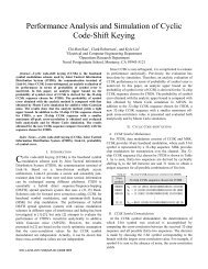
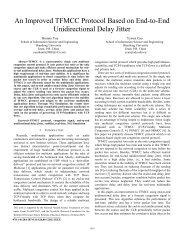
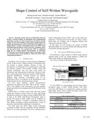
DIMA SYSTEM OVERVIEW<br />
The DIMA prototype system is based on COTS<br />
hardware integrated into a 6U Compact PCI Chassis.<br />
Figure 1 shows a diagram <strong>of</strong> the hardware blocks. The<br />
components within the Chassis include the Single Board<br />
Computer (SBC), which hosts the MAC, an FPGA<br />
motherboard and daughter boards, which host the PHY, an<br />
RF tuner, RF exciter, and a custom transmit/receive board<br />
built from COTS components.<br />
Custom RF Board<br />
DRS Tuner / Exciter<br />
Analog IF<br />
Nallatech Motherboard<br />
and Daughter Boards<br />
RS232<br />
Single Board Computer<br />
Compact PCI Chassis<br />
Rx<br />
Amp<br />
RF Tuner<br />
ADC<br />
10MHz Clk<br />
RF Exciter<br />
DAC<br />
clock clock<br />
FGPA Cores<br />
Transmit and Receive<br />
Chains<br />
cPCI<br />
Processing<br />
MAC<br />
Analog IF<br />
Figure 1: DIMA Prototype Hardware Block Diagram<br />
T/R<br />
Tx<br />
Amp<br />
Omni Antenna<br />
Linux<br />
T/R Ctrl<br />
RS232<br />
GBit Enet Hub<br />
2 <strong>of</strong> 6<br />
The SBC runs a Linux operating system and provides<br />
interfaces for receiving data through gigabit Ethernet<br />
(used by a separate laptop to host voice, video, chat, or<br />
packet generation applications) and for controlling the RF<br />
tuner and exciter through RS232. The MAC Layer is<br />
written as a Linux kernel driver, providing it access to the<br />
Linux network stack for sending and receiving IP packets.<br />
The MAC consists <strong>of</strong> four main functional blocks:<br />
• The MAC Common Parts Sublayer (MCPS), which<br />
provides the core MAC functionality (system access,<br />
bandwidth allocation, connection establishment, and<br />
connection maintenance).<br />
• The MAC Convergence Sublayer (MCS), which<br />
receives IP Layer Protocol Data Units (PDUs) and<br />
converts them to PDUs understood by the MCPS.<br />
• The PHY Layer Management Entity (PLME), which<br />
reads, write, and stores key PHY parameters,<br />
debugging information, and system performance<br />
metrics.<br />
• The MAC-PHY Interface, which communicates<br />
directly with the PHY through the PCI bus. The PCI<br />
bus provides the ability to receive hardware interrupts,<br />
perform Direct Memory Accesses (DMAs), and<br />
individually read and write hardware registers.<br />
The PHY Layer is implemented on COTS FPGA<br />
development boards. The three devices that made up the<br />
PHY are:<br />
• The MAC-PHY Convergence (MPC) chip, which<br />
handles the MAC-PHY interface as well as packet<br />
framing/de-framing functions.<br />
• The Physical Media Device (PMD), which contains<br />
the transmitter, RF interface, and parameter estimator.<br />
• The MUD receiver.<br />
The MPC device is a Virtex-2 V2000E FPGA residing<br />
on the FPGA motherboard, which handles mostly logic<br />
functions, and interfacing with the PCI bus. The PMD and<br />
MUD devices are both Virtex-4 SX-55 FPGAs located on<br />
separate daughter boards. The RF interface on the PMD<br />
connects to the RF exciter and tuner via the A/D and D/A<br />
converters on the daughter board, which put out / takes in<br />
analog IF signals. The tuner and exciter allow the DIMA<br />
waveform to communicate over a wide range <strong>of</strong> operating<br />
frequencies. The custom RF board consists <strong>of</strong> COTS<br />
amplifiers for both transmit and receive paths as well as a<br />
transmit/receive (T/R) switch that is controlled by the<br />
PMD. The prototype system is therefore a half-duplex<br />
transceiver whose default mode is reception, but it isolates<br />
the receive side whenever the radio needs to transmit. The<br />
air interface is through a single omni-directional antenna<br />
as the DIMA prototype waveform does not rely on
complex beam-forming or multiple-input multiple-output<br />
(MIMO) techniques.<br />
FPGA IMPLEMENTATION CONSIDERATIONS<br />
The biggest driver <strong>of</strong> complexity, and hence number <strong>of</strong><br />
FPGAs, in the design was the MUD receiver. Given a goal<br />
<strong>of</strong> fitting the core MUD algorithm within one FPGA,<br />
members <strong>of</strong> the algorithm development and hardware<br />
implementation teams worked together to select and<br />
optimize a MUD for performance based on the stated<br />
limitation. Initial trades relating to performance versus<br />
complexity, described in [2], pointed to the use <strong>of</strong> a<br />
recursive-least-squares (RLS) MUD [8]. Further<br />
simulations enabled a second layer <strong>of</strong> trades, which<br />
optimized the RLS MUD operating parameters to maintain<br />
the balance <strong>of</strong> required performance versus<br />
implementability on a single FPGA. Table 1 shows the<br />
final size <strong>of</strong> the PHY design as spread across the three<br />
devices.<br />
Table 1: DIMA FPGA Design Sizing<br />
Totals PMD (Virtex-4<br />
SX-55) % Used<br />
RLS (Virtex-4<br />
SX-55) % Used<br />
MPC (Virtex-2<br />
2000E) % Used<br />
DSP48s 435 19% 66% 0%<br />
BRAMs 260 29% 34% 37%<br />
Slices 40540 38% 86% 52%<br />
The MPC and PMD FPGAs are both utilized to a low<br />
degree, which supports going to a two FPGA design in the<br />
future (or a one FPGA design using a Virtex-5 device).<br />
The MUD FPGA is very highly utilized, using 86% <strong>of</strong> the<br />
available slices and 66% <strong>of</strong> the available DSP48s. All<br />
three chips used a high percentage <strong>of</strong> their input/output<br />
blocks, but integrating to one or two devices would<br />
alleviate this since more functions would exist on the same<br />
chip. This would reduce not only the required inputs and<br />
outputs between devices but also the slices dedicated to<br />
exchanging information between devices.<br />
Having such a highly utilized MUD FPGA reduced the<br />
speed at which the system could operate. This in turn<br />
affected the bandwidth <strong>of</strong> the system and hence the<br />
throughput <strong>of</strong> the network. The implementation team<br />
continued refining the overall design while the Systems<br />
Integration and Performance Characterization teams<br />
performed their functions. Hence, the performance<br />
numbers described in the results section are based on a<br />
non-full-rate design. Table 2 provides the clock speeds<br />
achieved in each device both the final design as well as the<br />
design used for performance characterization. The final<br />
PMD and RLS design speeds are 50% faster, which<br />
translates directly to 50% higher throughputs, though since<br />
3 <strong>of</strong> 6<br />
the bandwidth increases as clock speed increases, the<br />
spectral efficiency <strong>of</strong> the system will remain the same.<br />
Data<br />
Storage<br />
Table 2: DIMA FPGA Device Clock Speeds<br />
Device Final <strong>Implementation</strong><br />
Clock Speeds (MHz)<br />
Characterized Performance<br />
Clock Speeds (MHz)<br />
MPC 40 40<br />
PMD 200 135<br />
RLS 204 140<br />
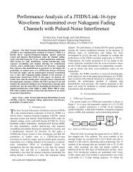
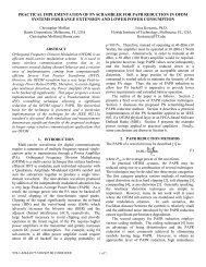
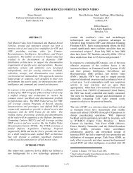
NON-REAL-TIME EXPERIMENTAL SETUP<br />
Figure 2: DIMA Non-<strong>Real</strong>-<strong>Time</strong> Test Block Diagram<br />
The Non-<strong>Real</strong>-<strong>Time</strong> (NRT) tests used three transmitters<br />
and one receiver as shown in Figure 2. Each node consists<br />
<strong>of</strong> the Tx/Rx hardware as depicted in Figure 1 (minus the<br />
T/R switch and with a new synchronization line input).<br />
Waveforms were generated in the MATLAB simulation<br />
environment and stored as binary data files containing IF<br />
waveforms and parameters (center frequency, time delay,<br />
attenuation) for all the transmitters. The receiver acted as<br />
a control node as it signaled all nodes to transmit via<br />
synchronization lines attached to each node. The<br />
transmitters then sent all their data while the receiver<br />
recorded the resulting waveform. The received waveform<br />
was then transferred into MATLAB and processed with<br />
fixed point PHY receiver algorithms.<br />
Tx2<br />
Remote<br />
User Control<br />
PC<br />
MATLAB Testbed<br />
Fixed Point DIMA<br />
PHY Transmitter<br />
Fixed Point DIMA<br />
PHY Receiver<br />
Ethernet<br />
30 m<br />
S<strong>of</strong>tware Defined Radio – Tx 1<br />
SBC FPGA Exciter<br />
S<strong>of</strong>tware Defined Radio – Tx 1<br />
30 m<br />
30 m<br />
Amp<br />
SBC FPGA Exciter Amp<br />
S<strong>of</strong>tware Defined Radio – Tx 1<br />
SBC FPGA Exciter Amp<br />
S<strong>of</strong>tware Defined Radio – Rx 1<br />
SBC FPGA Tuner Amp<br />
Tx3<br />
Rx<br />
Tx1<br />
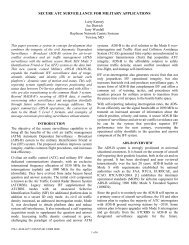
Figure 3: DIMA Non-<strong>Real</strong>-<strong>Time</strong> Test Field Locations
Table 3: DIMA Non-<strong>Real</strong>-<strong>Time</strong> Test Results (CBER = Channel Bit Error Rate,<br />
BER = Decoded Bit Error Rate, PER = Packet Error Rate).<br />
Experiment SNR Distribution SINR Distribution Total Packets Sent CBER BER PER<br />
Low SNR 5 Users @ 5dB 5 Users @ -6.4dB 100 4.8e-4 0 0%<br />
Near-Far 1 4 Users @ 5dB,<br />
1 User @ 35dB<br />
Near-Far 2 4 Users @ 5dB,<br />
1 User @ 45dB<br />
Near-Far 3 3 Users @ 5dB,<br />
2 User @ 45dB<br />
Near-Far 4 2 Users @ 5dB,<br />
3 User @ 30dB<br />
Near-Far 5 1 Users @ 5dB,<br />
4 User @ 30dB<br />
4 Users @ -40.0dB<br />
1 User @ 33.6dB<br />
4 Users @ -30.0dB<br />
1 User @ 23.6dB<br />
3 Users @ -43.dB<br />
2 Users @ 0.dB<br />
2 Users @ -29.8dB<br />
3 Users @ -3.0dB<br />
1 User @ -31.0dB<br />
4 Users @ -4.8dB<br />
To emulate more than three transmitters when only<br />
three were physically available, multiple transmit IF<br />
waveforms were synthesized together to be sent from each<br />
transmitter. This NRT testbed accomplished this by<br />
adding signals at IF after applying realistic carrier <strong>of</strong>fsets,<br />
time delays, and clock drifts to each signal to simulate<br />
multiple physical radios. The NRT test took place on a<br />
test range as depicted in Figure 3. The distance limit <strong>of</strong> 30<br />
meters was solely due to limitations <strong>of</strong> running power and<br />
synchronization cables around the test range.<br />
NON-REAL-TIME RESULTS<br />
The NRT test results verified that the fixed point PHY<br />
algorithm models meet the requirements for the PHY layer<br />
design. Table 3 summarizes the results and shows how the<br />
algorithms operated successfully at key power spreads (up<br />
to 40dB near-far suppression) with less than 1% PER (for<br />
packets with 512 byte payloads). The results also show<br />
where the algorithms breakdown as they could not<br />
maintain less than 1% PER with more than one user 40dB<br />
above the lowest power user.<br />
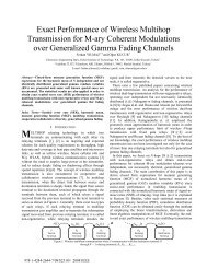
CBER<br />
10 0<br />
10 -2<br />
10 -4<br />
10 -6<br />
10<br />
2 4 6 8 10 12 14 16<br />
-10<br />
10 -8 NRT test results<br />
Theoretical Rayleigh Channel<br />
Theoretical AWGN Channel<br />
Theoretical Rician Channel (K factor 13)<br />
Eb/No<br />
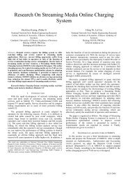
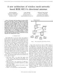
Figure 4: DIMA Test Range Channel Performance Results<br />
(Single User Tests, CBER = Channel Bit Error Rate, Eb/No =<br />
Energy per bit divided by Noise Spectral Density)<br />
4 <strong>of</strong> 6<br />
1000 1.1e-4 0 0%<br />
1000 3.6e-3 < 2e-5 < 1%<br />
300 3.5e-2 < 2e-4 < 2%<br />
200 2.1e-4 0 0%<br />
200 4.3e-4 0 0%<br />
Other key tests helped to verify parameter estimation<br />
performance (resulting in a probability <strong>of</strong> detection, Pd, <strong>of</strong><br />
0.999, and a probability <strong>of</strong> false alarm, Pfa, <strong>of</strong> 1x10 -8 at<br />
5dB SNR), quantify hardware imperfections (clock<br />
accuracies measured as below 0.5 ppm and carrier <strong>of</strong>fsets<br />
<strong>of</strong> ±50 Hz among others), and observe characteristics <strong>of</strong><br />
the propagation environment on the test range. Figure 4<br />
shows single user performance results for a number <strong>of</strong><br />
theoretical channels as well as measured test range results<br />
using the NRT testbed. The test range channel closely<br />
resembled a Rician channel with a K factor <strong>of</strong> 13, which<br />
was expected due to the moderately low number <strong>of</strong> local<br />
scatterers in the test environment.<br />
REAL-TIME EXPERIMENTAL SETUP<br />
Figure 5 shows the locations on the test range <strong>of</strong> the<br />
radio nodes for the <strong>Real</strong>-<strong>Time</strong> (RT) tests.<br />
Tx1<br />
175 m<br />
Tx3<br />
Tx2<br />
Rx<br />
120 m<br />
6 m<br />
Tx4<br />
Figure 5: DIMA <strong>Real</strong>-<strong>Time</strong> Test Field Locations<br />
Tx5
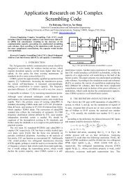
Tests consisted <strong>of</strong> six radio nodes, as described in<br />
Figure 1 and depicted in Figure 6. Each node acted as a<br />
transceiver and carried out the DIMA protocol as<br />
described in Eisenberg [3]. Ethernet connected the nodes<br />
to a test terminal to allow for remote configuration and<br />
control <strong>of</strong> the network. This remote control allowed the<br />
system to test various power spread scenarios from static<br />
location by varying the transmit power at each node.<br />
Custom RF<br />
Board<br />
Tuner<br />
Exciter<br />
FPGA Board<br />
Single Board<br />
Computer<br />
Figure 6: DIMA <strong>Real</strong>-<strong>Time</strong> Prototype Hardware (Photo)<br />
Performance testing utilized a random packet generator<br />
call Iperf to measure throughput, PER, and latency jitter at<br />
the application layer. Custom s<strong>of</strong>tware provided PHY<br />
layer throughput, PER, and signal-to-noise-ratio (SNR)<br />
estimates. Other applications, including TeamSpeak<br />
(voice and chat) and VLC Player (streaming video) were<br />
used to demonstrate the prototype system’s compatibility<br />
with any type <strong>of</strong> IP layer data.<br />
Other key RT test parameters included:<br />
• Carrier Frequency: 391 MHz<br />
• Bandwidth: 2.5 MHz<br />
• Test Duration: 5 minutes (unless otherwise stated)<br />
• Traffic Pr<strong>of</strong>ile: 5 users sending data to 1 receiver,<br />
many-to-one (unless otherwise stated)<br />
5 <strong>of</strong> 6<br />
Performance <strong>of</strong> the DIMA system was compared to<br />
results from tests using the 802.11 protocol (in ad-hoc<br />
mode) to show the spectral efficiency and latency<br />
improvements provided by the MUD technology. At the<br />
target SNR (5dB), both DIMA and 802.11 have an Eb/N0<br />
<strong>of</strong> approximately 15dB, resulting in 802.11 operating in<br />
the Direct Sequence Spread Spectrum (DSSS) 2Mbps<br />
mode. In this mode, 802.11 had a spectral efficiency <strong>of</strong><br />
0.0526 bits/Hz (1157kbps in 22MHz <strong>of</strong> bandwidth). This<br />
value was calculated using analytic models [9], verified<br />
through OPNET simulations, and validated by measuring<br />
the performance <strong>of</strong> a real over-the-air ad-hoc 802.11<br />
network.<br />
REAL-TIME RESULTS<br />
The RT test results validated that the DIMA concept<br />
can provide large gains in terms <strong>of</strong> spectral efficiency<br />
(aggregate capacity) and latency jitter over comparable adhoc<br />
systems. Table 4 summarizes the RT test results. In<br />
the baseline comparison at low SNR, DIMA achieved 3.5<br />
times the spectral efficiency <strong>of</strong> the 802.11 system. The<br />
improvement in latency jitter (which is very important in<br />
streaming applications) was even greater as DIMA<br />
provided an average latency jitter 11 times lower than the<br />
802.11 system. This latency jitter reduction was enabled<br />
by the DIMA system’s ability to allow more than one node<br />
to transmit at the same time. While the overall throughput<br />
<strong>of</strong> the 802.11 system was higher due to its much greater<br />
bandwidth (22MHz compared to DIMA’s 2.5MHz),<br />
latency jitter is unaffected by bandwidth and hence it is a<br />
good metric for measuring how long nodes are forced to<br />
wait between successive channel accesses.<br />
As in the NRT tests, various SNR distributions were<br />
studied to analyze the DIMA system’s near-far<br />
suppression capabilities. As expected, the performance <strong>of</strong><br />
the RT system was slightly below the results obtained<br />
from the NRT tests. As can be seen when comparing tests<br />
with four users at 5dB and one user at 35dB SNR, the<br />
NRT results showed 0% PHY PER while the RT system<br />
only achieved 0.91% PER. These differences are<br />
attributable to a number <strong>of</strong> factors. First, the fixed-point<br />
models used in the NRT tests only covered the MUD<br />
receiver algorithms. Therefore, quantization effects from<br />
the IF-to-baseband conversion and parameter estimation<br />
functions reduced performance. In addition, system level<br />
impairments due to the MAC-PHY interface and to the<br />
MAC being implemented on a non-real-time Linux kernel<br />
affected the RT system. Despite these effects, the RT<br />
DIMA system still demonstrated the benefits <strong>of</strong> MUD<br />
receiver technology.
Table 4: DIMA <strong>Real</strong>-<strong>Time</strong> Test Results (SINR = signal-to-interf.-plus-noise-ratio). SNR values averaged over the test duration and are<br />
not precisely at target values due to min. atten. setting increments <strong>of</strong> 1dB. Throughput and Capacity measured at Application Layer.<br />
Experiment Aggregate Aggregate PHY Layer App. Layer App. Layer SNR (dB) SINR (dB)<br />
Throughput Capacity PER PER Latency Jitter<br />
(bits/sec/Hz)<br />
(ms)<br />
802.11<br />
2Mbps mode<br />
1126kbps 0.0526<br />
802.11 Baseline Comparison Test<br />
0% 0% 54 5 (target)<br />
DIMA <strong>Real</strong>-<strong>Time</strong> System<br />
6 <strong>of</strong> 6<br />
5 (no interference due to<br />
collision avoidance)<br />
Low SNR 460kbps 0.184 0.5% 0% 5 5.2, 5.3, 5.4, 5.5, 5.5 -6.5, -6.5, -6.3, -6.2, -6.2<br />
Near-Far 1<br />
(30dB Spread)<br />
NF2 (30dB Spread,<br />
2 Loud Users)<br />
NF3<br />
(Distributed Power)<br />
Stability Test<br />
(4 hours)<br />
460kbps 0.184<br />
460kbps 0.184<br />
460kbps 0.184<br />
460kbps 0.184<br />
Additional RT tests not summarized in Table 4<br />
demonstrated various other DIMA system capabilities.<br />
MAC functionality tests included:<br />
• Talking Pairs: demonstrated multiple concurrent<br />
transmissions where each receiver filtered out<br />
unintended signals and successfully received their<br />
intended packets (three concurrent sessions were<br />
possible with six nodes).<br />
• Dying Node: demonstrated infrastructure-less<br />
operations and the lack <strong>of</strong> any single-point-<strong>of</strong>-failure.<br />
Each node was removed from the network individually<br />
and in groups without detrimental effects on any nodes<br />
remaining in the network.<br />
• Multicast: demonstrated ability to send packets to<br />
multiple recipients simultaneously instead <strong>of</strong> requiring<br />
separate transmissions (Broadcast is a special case <strong>of</strong><br />
multicast that is also supported).<br />
To test the stability <strong>of</strong> the DIMA system, the network was<br />
configured for five nodes continuously streaming data to<br />
one receiver at low SNR for four hours. During this<br />
period, over 350,000 random 512byte packets were<br />
transmitted simultaneously from each <strong>of</strong> the five<br />
transmitters with only a 0.40% PER. Finally, high<br />
spreading mode tests were conducted where each symbol<br />
was spread by an additional factor <strong>of</strong> 8 chips per symbols<br />
on top <strong>of</strong> the baseline spreading rate. This mode was<br />
developed to allow operation at even lower SNR ranges.<br />
CONCLUSIONS<br />
The DIMA program successfully implemented a realtime<br />
ad-hoc communications system, which demonstrated<br />
the capacity and latency gains possible by utilizing a<br />
0.9% 0% 10<br />
1.5% 0.1% 10<br />
0.1% 0% 9<br />
5.5, 5.0, 5.1, 5.5,<br />
34.7<br />
5.2, 5.6, 5.0,<br />
30.1, 30.0<br />
5.0, 10.3, 17.2,<br />
23.1, 29.9<br />
-29.3, -29.7, -29.6, -29.2,<br />
23.1<br />
-27.9, -27.5, -28.1,<br />
0.1, -0.2<br />
-25.9, -20.6, -13.6,<br />
-7.1, 5.6<br />
0.4% 0% 5 5.8, 5.4 5.3, 5.6, 5.2 -6.1, -6.6, -6.8, -6.4, -5.6<br />
MUD-based receiver. In military applications, having<br />
access to robust communications without infrastructure or<br />
single-points-<strong>of</strong>-failure, while sending more data in less<br />
bandwidth than currently possible can enable new<br />
capabilities and missions that enhance the effectiveness <strong>of</strong><br />
the warfighter.<br />
REFERENCES<br />
[1] S. Verdu, <strong>Multiuser</strong> <strong>Detection</strong>, Cambridge University<br />
Press, Cambridge, UK, 2003.<br />
[2] R. Lupas, S. Verdu, “Near-far resistance <strong>of</strong> multiuser<br />
detectors in asynchronous code-division multiple-access<br />
channels”, IEEE Trans. Comm. Vol 38, April 1990.<br />
[3] R. Learned et al. “Interference Multiple Access Wireless<br />
Network Demonstration <strong>Enabled</strong> by <strong>Real</strong>-<strong>Time</strong> <strong>Multiuser</strong><br />
<strong>Detection</strong>”, Proc IEEE RWS, Orlando, Fl, 2008.<br />
[4] Y. Eisenberg, K. Conner, M. Sherman, J. Niedzwiecki, R.<br />
Brothers, “MUD <strong>Enabled</strong> Media Access Control for High<br />
Capacity, Low-Latency Spread Spectrum Comms”,<br />
Proceedings <strong>of</strong> the IEEE MILCOM, Orlando, FL, 2007.<br />
[5] Mobile Station-Base Station Compatibility Standard for<br />
Dual-Mode Wide-Band Spread Spectrum Cellular System<br />
TIA/EIA Interim Standard 95 (IS-95), (amended as IS-95-<br />
A May 1995), July 1993.<br />
[6] M. Mouly, M. B. Pautet, “Current evolution <strong>of</strong> the GSM<br />
systems,” IEEE Pers. Commun., vol. 2, pp. 9-19, Oct 1995.<br />
[7] IEEE Std. 802.11-1999 Part 11: Wireless LAN Medium<br />
Access Control (MAC) and Physical Layer (PHY)<br />
specifications, Reference number ISO/IEC 8802-<br />
11:1999(E), IEEE Std. 802.11, 1999 edition, 1999.<br />
[8] S. Hayken, Adaptive Filter Theory, Prentice Hall, Upper<br />
Saddle River, NJ, Third Edition, 1996.<br />
[9] G. Bianchi, Performance analysis <strong>of</strong> the IEEE 802.11<br />
distributed coordination function. IEEE Journal on<br />
Selected Areas in Communications, 18(3):535-547, March<br />
2000.