CANOpen Manual
CANOpen Manual
CANOpen Manual

Create successful ePaper yourself
Turn your PDF publications into a flip-book with our unique Google optimized e-Paper software.
2. Installation<br />
2.1 Electrical Connection<br />
The inclinometer is connected via 8 pin round<br />
connector<br />
Instructions to mechanically install and<br />
electrically connect the inclinometer<br />
Do not connect the inclinometer<br />
under power!<br />
Do not stand on the inclinometer!<br />
Avoid mechanical load!<br />
Pin Description<br />
1 24 V Supply voltage<br />
2<br />
3<br />
4 0 V Supply voltage<br />
5 CAN Low<br />
6 CAN Ground<br />
7 CAN High<br />
8<br />
Tabelle 1 Connector Assignment<br />
8 pin round connector<br />
connector male inlay<br />
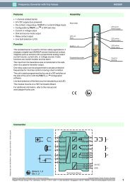
2.2 Bus Termination<br />
If the inclinometer is connected at the end or<br />
beginning of the bus the termination resistor<br />
must be switched on. The termination resistor is<br />
switched on when the dip-switch 8 is in the ‘ON’<br />
position. To switch the resistor on, the cap of the<br />
inclinometer has to be unscrewed.<br />
There is a resistor provided in the inclinometer,<br />
which must be used as a line termination on the<br />
last device.<br />
2.3 Bus address<br />
ON OFF<br />
The setting of the node number is achieved via<br />
SDO-Object (see 4.4). Possible (valid)<br />
addresses lie between 0 and 96 whereby every<br />
address can only be used once.<br />
The CANopen inclinometer adds<br />
internal 1 to the adjusted device<br />
address.<br />
Page 8 UME-AGS-CAN Version 09/04