CANOpen Manual
CANOpen Manual
CANOpen Manual

Create successful ePaper yourself
Turn your PDF publications into a flip-book with our unique Google optimized e-Paper software.
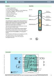
Installation hints<br />
Both the cable shielding and the metal housings<br />
of encoders and subsequent electronics have a<br />
shielding function. The housing must have the<br />
same potential and be connected to the main<br />
signal ground over the machine chassis or by<br />
means of a separate potential compensating<br />
line. Potential compensating lines should have a<br />
minimum cross section of 6 mm2.<br />
Do not lay signal cable in the direct vicinity of<br />
interference sources (air clearance > 100 mm (4<br />
in.).<br />
6. Models/Ordering Description<br />
Description Typekey<br />
A minimum spacing of 200 mm (8 in.) to<br />
inductors is usually required, for example in<br />
switch-mode power supplies.<br />
Configure the signal lines for minimum length<br />
and avoid the use of intermediate terminals.<br />
In metal cable ducts, sufficient decoupling of<br />
signal lines from interference signal transmitting<br />
cable can usually be achieved with a grounded<br />
partition.<br />
Absolute inclinometer AGS- . . . 2 . . 1 H0 . . . -<br />
Measuring range<br />
Number of axis<br />
005<br />
015<br />
030<br />
Interface CA<br />
Version<br />
Mechanical construction horizontal<br />
Dynamik 2 mPas<br />
Connection connector, 8 pin P8M<br />
1 m cable CRW<br />
Option without -<br />
Tabelle 13 Ordering Description<br />
Version 09/04 UME-AGS-CAN Page 35