CANOpen Manual
CANOpen Manual
CANOpen Manual

Create successful ePaper yourself
Turn your PDF publications into a flip-book with our unique Google optimized e-Paper software.
INCLINOMETER WITH CAN-BUS INTERFACE<br />
USER MANUAL
Imprint<br />
FRABA POSITAL GmbH<br />
Schanzenstraße 35<br />
D-51063 Köln<br />
Telefon +49 (0) 221 96213-0<br />
Telefax +49 (0) 221 96213-20<br />
Internet http://www.posital.com<br />
e-mail info@posital.com<br />
Copyright<br />
The company FRABA POSITAL GmbH claims<br />
copyright on this documentation. It is not allowed to<br />
modify, to extend, to hand over to a third party and<br />
to copy this documentation without written approval<br />
by the company FRABA POSITAL GmbH. Nor is<br />
any liability assumed for damages resulting from<br />
the use of the information contained herein.<br />
Further, this publication and features described<br />
herein are subject to change without notice.<br />
Alteration of Specifications reserved<br />
Technical specifications, which are described in<br />
this manual, are subject to change due to our<br />
permanent strive to improve our products.<br />
Disclaimer of Warranty<br />
FRABA POSITAL GmbH makes no<br />
representations or warranties, either express or<br />
implied, by or with respect to anything in this<br />
manual, and shall not be liable for any implied<br />
warranties of merchantability and fitness for a<br />
particular purpose or for any indirect, special, or<br />
consequential damages.<br />
Version date: 18. April 2005<br />
Version number: 1.4<br />
Article number:<br />
Author: Efthimios Ioannidis<br />
Page 2 UME-AGS-CAN Version 09/04
1. Introduction......................................................4<br />
1.1 Inclinometer .....................................................4<br />
1.2 CANopen technology .......................................4<br />
1.3 CAN Communication Reference Model ...........6<br />
1.4 Definitions ........................................................7<br />
2. Installation........................................................8<br />
2.1 Electrical Connection .......................................8<br />
2.2 Bus Termination...............................................8<br />
2.3 Bus address.....................................................8<br />
2.4 Troubleshooting ...............................................9<br />
2.4.1 Power on – Inclinometer doesn’t respond.....9<br />
2.4.2 Malfunction of the position value during<br />
transmission...........................................................9<br />
2.4.3 Too much ERROR-Frames...........................9<br />
2.4.4 Information....................................................9<br />
3. Device Configuration.....................................10<br />
3.1. CANopen data transmission .........................10<br />
3.1.1 The COB-ID ................................................10<br />
3.1.2 The Command Byte....................................11<br />
3.1.3 The Object Directory ...................................12<br />
3.2 Operational Status .........................................14<br />
3.2.1 Status: Operational .....................................14<br />
3.2.2 Status: Pre-Operational...............................14<br />
3.2.3 Reset of the inclinometer ............................15<br />
3.3 Transmission of the Actual Position...............15<br />
4. Programming................................................. 15<br />
4.1 Resolution......................................................16<br />
4.1.1 Programming example: Resolution.............17<br />
4.2 Operating ParameterLongitudinal ..................17<br />
4.2.1 Programming example: Operating Parameter<br />
Longitudinal .........................................................18<br />
4.3 Preset Value Longitudinal ..............................19<br />
4.3.1 Programming example: Preset value..........19<br />
4.4 Node-Guarding ..............................................20<br />
4.4.1 Guard-Time.................................................20<br />
4.4.3 Lifetime-Factor............................................21<br />
4.5 Heartbeat-Function ........................................22<br />
4.5.1 Heartbeat-Consumer: .................................22<br />
4.5.2 Programming example: Heartbeat-Consumer23<br />
4.5.3 Heartbeat-Producer: ...................................23<br />
4.5.4 Programming example:Heartbeat-Producer24<br />
4.6 Changing the node number............................24<br />
4.6.1 Example: Changing the node number.........25<br />
4.7 Adjusting the baudrate ...................................26<br />
4.7.1 Example : Adjusting the baudrate ...............27<br />
4.8 Transmission Mode........................................27<br />
4.8.1 Cyclic Mode.................................................27<br />
4.8.2 Disable the cyclic mode...............................28<br />
4.8.3 Sync Mode ..................................................28<br />
4.8.4 Example: Number of Sync telegrams..........29<br />
4.8.5 Polled Mode ................................................29<br />
4.9 Memory Transfer............................................30<br />
4.10 Restore default parameters..........................31<br />
5. Technical Data................................................31<br />
5.1. Electrical Data ...............................................31<br />
5.2. Mechanical Data ...........................................32<br />
Environmental Conditions ....................................32<br />
5.3 Mechanical Drawings .....................................33<br />
5.3.1 Bottom View................................................33<br />
5.3.2 Site View .....................................................33<br />
5.3.3 Front View...................................................34<br />
5.3.4 Top View .....................................................34<br />
Installation hints ...................................................35<br />
6. Models/Ordering Description ........................35<br />
6.1 Accessories and documentation ....................36<br />
7 List of Tables...................................................36<br />
Version 09/04 UME-AGS-CAN Page 3
1. Introduction<br />
This manual describes the implementing and<br />
configuration of an inclinometer with CANopen<br />
interface. The device fullfills the requirements of<br />
a CANopen device regarding the device<br />
specification DS410 of the CANopen user group.<br />
1.1 Inclinometer<br />
The AGS CAN-Bus is a heavy duty absolute<br />
inclinometer with conductive technology and a<br />
fieldbus interface utilizing the CANBus protocol.<br />
With a maximum measuring range of +/- 30° and<br />
resolution up to 0.001°, these inclinometers are<br />
used in a wide variety of position sensing<br />
applications for the measuring of inclinations.<br />
Mechanical features include an aluminum<br />
housing and IP66 protection. Electrical features<br />
include a linear and temperature compensated<br />
characteristic line, integrated SMD circuits, and<br />
over voltage peak protection. The inclinometer<br />
can be connected to a bus via an 8 pin<br />
connector. The termination resistor can be<br />
switched on by using a dip-switch. In addition<br />
the resolution is changeable via SDO object.<br />
For further information about the setup of a<br />
CANopen network please refer<br />
http://www.posital.com/products/encoder_abc/en<br />
coder_abc.html<br />
Open functions. The following modes can be<br />
programmed and enabled or disabled:<br />
- Polled Mode<br />
- Cyclic Mode<br />
- Sync Mode<br />
The protocol supports the programming of the<br />
following additional functions:<br />
- Resolution<br />
- Preset value<br />
- Baudrate<br />
- Node number<br />
The general use of inclinometer with CAN-Bus<br />
interface using the CAN Open protocol is<br />
guaranteed.<br />
1.2 CANopen technology<br />
CAN stands for Controller Area Network and<br />
was developed by the company Bosch for<br />
applications within the automobile area. In the<br />
meantime CAN has become increasingly used<br />
for industrial applications. CAN is a multi-<br />
masterable system, i.e. all users can access the<br />
bus at any time as long as it is free. CAN<br />
doesn`t operate with addresses but with<br />
message identifiers. Access to the bus is<br />
performed according to the CSMA/CA principle<br />
(carrier sense multiple access with collision<br />
avoidance), i.e. each user listens if the bus is<br />
free, and if so, is allowed to send messages. If<br />
two users attempt to access the bus<br />
simultaneously, the one with the highest priority<br />
(lowest identifier) receives the permission to<br />
send. Users with lower priority interrupt their<br />
data transfer and will access the bus when it is<br />
free again. Messages can be received by every<br />
participant. Controlled by an acceptance filter<br />
the participant accepts only messages that are<br />
intended for it.<br />
CANopen<br />
Transmission Technology: Two-core cable<br />
Baud rates: 20 kBaud up to 1 MBaud<br />
Participants: maximum 127<br />
Cable Length: 30 m for 1 MBaud<br />
5000 m for 20 kBaud<br />
Page 4 UME-AGS-CAN Version 09/04
The data communication is done via message<br />
telegrams. In general, telegrams can be split in a<br />
COB-Identifier and up to 8 following bytes. The<br />
COB-Identifier, which determines the priority of<br />
the message, is made from the function code<br />
and the node number.<br />
The node number is uniquely assigned to each<br />
user. With the AGS inclinometer this number can<br />
be set via SDO object.<br />
The function code varies according to the type of<br />
message transmitted:<br />
- Administrative messages (LMT, NMT)<br />
- Service data objects (SDOs)<br />
- Process data Objects (PDOs)<br />
- pre-defined messages (synchronization,<br />
emergency messages)<br />
PDOs (Process Data Objects) are needed for<br />
real time data exchange. Since this messages<br />
possess a high priority, the function code and<br />
therefore the identifier are low. SDOs (service<br />
data objects) are necessary for the bus node<br />
configuration (e.g. transfer of device<br />
parameters). Because these message telegrams<br />
are tranferred acyclicly (usually only while<br />
powering up the network), the priority is low.<br />
FRABA inclinometers with CANopen interface<br />
support all CANopen functions. The following<br />
operating modes can be programmed:<br />
- Polled mode:<br />
The position value is only given upon<br />
request<br />
- Cyclic Mode:<br />
The position value is written cyclically<br />
(interval adjustable) to the bus<br />
- Sync mode:<br />
After receiving a sync message by the<br />
host, the inclinometer answers with the<br />
current process value. If a node is not<br />
required to answer after each sync<br />
message, a parameter sync counter<br />
can be programmed to skip a certain<br />
number of sync messages before<br />
answering again<br />
- Change of state mode:<br />
The position value is transferred when<br />
changing<br />
Further functions (preset, resolution,etc..) can be<br />
parameterized. FRABA inclinometers<br />
correspond with the class 2 profile for<br />
inclinometer (DSP 410), whereby the<br />
characteristics of inclinometer with CANopen<br />
interface are defined.<br />
The link to the bus is made by a 8 pin connector.<br />
For configuration and parameterization various<br />
software tools are available from different<br />
providers. With the help of the provided EDS file<br />
(electronic datasheet) simple line-up and<br />
programming are possible.<br />
Version 09/04 UME-AGS-CAN Page 5
1.3 CAN Communication Reference Model<br />
The communication concept can be described similar to the ISO-OSI Reference Model:<br />
Device A Device B Device C Device X<br />
CAN Bus<br />
The communication model* supports<br />
synchronous and asynchronous messages. With<br />
respect to the functionality four different<br />
message objects are provided:<br />
Administrational Messages (LMT, NMT)<br />
Service Data Messages (SDO)<br />
Process Data Messages (PDO)<br />
Pre-defined Messages (Synchronisation and<br />
Emergency Messages)<br />
Further information is available at:<br />
CAN in Automation (CiA) International Users<br />
and Manufacturers Group e.V.<br />
Am Weichselgarten 26<br />
D-91058 Erlangen<br />
(*) Reference: CAN Application Layer for<br />
Industrial Applications<br />
CiA Draft Standard 201 ... 207, Version 1.1<br />
CAL-based Communication Profile for<br />
Industrial Systems<br />
CiA Draft Standard 301<br />
ISO/OSI Layer 7: CAL<br />
NMT DBT LMT CMS<br />
ISO/OSI Layer 2: Data Link Layer<br />
ISO/OSI Layer 1: Physical Layer<br />
Page 6 UME-AGS-CAN Version 09/04
1.4 Definitions<br />
CAN Controller Area Network<br />
CAL CAN Application Layer<br />
CMS CAN Message Specification.<br />
One of the service elements of the<br />
application layer in the CAN Reference<br />
Model.<br />
COB Communication Object. (CAN message)<br />
A unit of transportation in a CAN Network.<br />
Data must be sent across a Network<br />
inside a COB.<br />
COB-ID COB-Identfier. Identifies a COB uniquely<br />
in a Network. The identifier determines<br />
the<br />
priority of that COB.<br />
LMT Layer Management. One of the service<br />
elements of the application layer in the<br />
CAN<br />
Reference Model. It serves to configure<br />
parameters of each layer in the CAN<br />
Reference Model.<br />
NMT Network Management. One of the service<br />
elements of the application layer in the<br />
CAN<br />
Reference Model. It performs initialisation,<br />
configuration and error handling in a CAN<br />
network.<br />
SDO Service Data Object. A data object with<br />
low priority to configure a CAN node.<br />
PDO Process Data Object. A data object with<br />
high priority to transmit data in<br />
synchronous and<br />
asynchronous modes.<br />
Additionally, following abbreviations are used in the<br />
manual:<br />
FC Function code. It determines the kind of<br />
message, which is sent across the CAN<br />
network.<br />
NN Node number. It determines uniquely the<br />
CAN device.<br />
PV Preset value<br />
PCV Process value<br />
Version 09/04 UME-AGS-CAN Page 7
2. Installation<br />
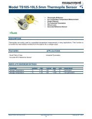
2.1 Electrical Connection<br />
The inclinometer is connected via 8 pin round<br />
connector<br />
Instructions to mechanically install and<br />
electrically connect the inclinometer<br />
Do not connect the inclinometer<br />
under power!<br />
Do not stand on the inclinometer!<br />
Avoid mechanical load!<br />
Pin Description<br />
1 24 V Supply voltage<br />
2<br />
3<br />
4 0 V Supply voltage<br />
5 CAN Low<br />
6 CAN Ground<br />
7 CAN High<br />
8<br />
Tabelle 1 Connector Assignment<br />
8 pin round connector<br />
connector male inlay<br />
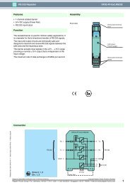
2.2 Bus Termination<br />
If the inclinometer is connected at the end or<br />
beginning of the bus the termination resistor<br />
must be switched on. The termination resistor is<br />
switched on when the dip-switch 8 is in the ‘ON’<br />
position. To switch the resistor on, the cap of the<br />
inclinometer has to be unscrewed.<br />
There is a resistor provided in the inclinometer,<br />
which must be used as a line termination on the<br />
last device.<br />
2.3 Bus address<br />
ON OFF<br />
The setting of the node number is achieved via<br />
SDO-Object (see 4.4). Possible (valid)<br />
addresses lie between 0 and 96 whereby every<br />
address can only be used once.<br />
The CANopen inclinometer adds<br />
internal 1 to the adjusted device<br />
address.<br />
Page 8 UME-AGS-CAN Version 09/04
2.4 Troubleshooting<br />
2.4.1 Power on – Inclinometer doesn’t<br />
respond<br />
Problem:<br />
The bus is active but the installed inclinometer<br />
transmitted the false node number.<br />
Possible solution:<br />
- modus pre-operational<br />
- adressing the inclinometer via SDO<br />
- reset or power off<br />
- power on<br />
2.4.2 Malfunction of the position value<br />
during transmission<br />
Problem:<br />
During the transmission of the position value<br />
occasional malfunctions occur. The CAN bus<br />
can be temporabily in the bus off state also.<br />
Possible solution:<br />
Check, if the last bus nodes have switched on<br />
the terminal resistor. If the last bus node is an<br />
inclinometer the terminal resistor is to activate.<br />
2.4.3 Too much ERROR-Frames<br />
Problem:<br />
The bus load is too high in case of too much<br />
error frames.<br />
Possible solution:<br />
Check if all bus node has the same baudrate. If<br />
one node has another baudrate error frames are<br />
produced automatically. The setting of the<br />
baudrate is descripted in this manual under 4.6.<br />
2.4.4 Information<br />
Notice: The changing of baudrate and node<br />
number is only valid after a new power up, NMT<br />
Reset or the store parameters command.<br />
Version 09/04 UME-AGS-CAN Page 9
3. Device Configuration<br />
3.1. CANopen data transmission<br />
The data transmission in the CAN network is<br />
realised by message telegrams. Basically, these<br />
Telegrams can be divided into the COB-ID and 8<br />
following bytes as shown in the table below:<br />
COB-ID Command Index Subindex Service-/Process- Data<br />
11 Bit Byte 0 Byte 1 Byte 2 Byte 3 Byte 4 Byte 5 Byte 6 Byte 7<br />
3.1.1 The COB-ID<br />
The 11 Bit of COB-Identifier is built as follows:<br />
10 9 8 7 6 5 4 3 2 1 0<br />
Function code Node number<br />
X X X X X X X X X X X X: free selectable<br />
The COB-Identifier determines uniquely the<br />
message object. It is built by the function code,<br />
identifying the message class and the node<br />
number, which determines the inclinometer. The<br />
node number can be adjusted by on customer<br />
request by a SDO.<br />
Following function codes are available: (rx) and (tx) as seen by the master !<br />
Object Function Code (Binary) Result. COB-ID Priority Class*<br />
NMT 0000 0 0<br />
SYNC 0001 128 0<br />
Emergency 0001 129 - 255 0,1<br />
PDO (rx) 0011 385 - 511 1,2<br />
PDO (tx) 0100 513 - 639 2<br />
PDO (rx) 0101 641 - 767 2,3<br />
PDO (tx) 0110 769 - 895 3,4<br />
SDO (rx) 1011 1409 - 1535 6<br />
SDO (tx) 1100 1537 - 1663 6,7<br />
Tabelle 2 Overview priority of the CANopen objects<br />
*Priority: 0 = highest priority, 7 = lowest priority<br />
Low High Low → → High<br />
Page 10 UME-AGS-CAN Version 09/04
3.1.2 The Command Byte<br />
The command byte contents the kind of telegram<br />
which is sent across the CAN network. One divides<br />
three kinds of telegrams: a Set-Parameter-<br />
Telegram (Domain Download), a Request-<br />
Telegram (Domain Upload) and Warnings.<br />
The Set-Parameter-Telegram is used to send<br />
parameter data to the inclinometer (node) for<br />
configuration.<br />
The Request-Telegram is used by the master to<br />
read back stored parameters from a node.<br />
Warnings are sent by the inclinometer to the<br />
master, if a sent telegram cannot be processed<br />
accordingly.<br />
Command Function Telegram Description<br />
22h Domain Download Request Parameter to inclinometer<br />
60h Domain Download Confirmation Parameter received<br />
40h Domain Upload Request Parameter request<br />
43h, 4Bh, 4Fh (*) Domain Upload Reply Parameter to Master<br />
80 h Warning Reply Transmission error<br />
Tabelle 3 Command description<br />
(*)The value of the command byte depends on the data length of the called parameter:<br />
Command Data length Data length<br />
43h 4 Byte Unsigned 32<br />
4Bh 2 Byte Unsigned 16<br />
4Fh 1 Byte Unsigned 8<br />
Tabelle 4 Data length against command byte<br />
Version 09/04 UME-AGS-CAN Page 11
3.1.3 The Object Directory<br />
The data transmission according to CAL is realised<br />
exclusively by object oriented data messages. The<br />
objects are classified in groups by an index record.<br />
Each index entry can be subdivided by sub-<br />
indices. The overall layout of the standard object<br />
dictionary is shown beside:<br />
Following objects according to the<br />
communication profile CAN OPEN (refer<br />
Tabelle 6 Object dictionary according DS301<br />
Index (hex) Object<br />
0000 not used<br />
0001-001F Static Data Types<br />
0020-003F Complex Data Types<br />
0040-005F Manufacturer Specific Data Types<br />
0060-0FFF Reserved for further use<br />
1000-1FFF Communication Profile Area<br />
2000-5FFF Manufacturer Specific Profile Area<br />
6000-9FFF Standardised Device Profile Area<br />
A000-FFFF Reserved for further use<br />
Tabelle 5 General object dictionary<br />
toDS301) are implemented into the inclinometer<br />
encoder:<br />
Index Subindex Object Name Data Length Attr.<br />
1000h VAR Device type Unsigned32 const<br />
1001h VAR error register Unsigned8 ro<br />
1002h VAR manufacturer status register Unsigned32 ro<br />
1003h ARRAY pre-defined error field Unsigned32 ro<br />
1004h Reserved for compatibility reason<br />
1005h VAR COB-ID SYNC-message Unsigned32 rw<br />
1008h VAR device name Vis-String const<br />
1009h VAR hardware version Vis-String const<br />
100Ah VAR software version Vis-String const<br />
100Bh Reserved for compatibility reason<br />
1010h 1h VAR Store parameters Unsigned32 rw<br />
1011h 1h VAR Restor parameters Unsigned32 rw<br />
1016h ARRAY Consumer Heartbeat Time Unsigned32 ro<br />
1017h VAR Producer Heartbeat Time Unsigned32 rw<br />
1800h RECORD Communication parameter PDO 1 ro<br />
1800h 0h VAR number of supp. entries Unsigned8 ro<br />
1800h 1h VAR COB-ID used by PDO Unsigned32 rw<br />
1800h 2h VAR transmission type Unsigned8 rw<br />
1801h RECORD Communication parameter PDO 2 ro<br />
1801h 0h VAR number of supp. entries Unsigned8 ro<br />
1801h 1h VAR COB-ID used by PDO Unsigned32 rw<br />
1801h 2h VAR transmission type Unsigned8 rw<br />
Page 12 UME-AGS-CAN Version 09/04
Index Subindex Objekt Name Datenlänge Attr.<br />
6000h VAR Resolution Unsigned16 rw<br />
6010h VAR Slope Longitudinal Signed16 ro<br />
6011h VAR Operating Parameter Longitudinal Unsigned8 rw<br />
6012h VAR Preset Longitudinal Signed16 rw<br />
6020h VAR Slope Lateral Signed16 ro<br />
6021h VAR Operating Parameter Lateral Unsigned8 rw<br />
6022h VAR Presetwert Lateral Signed16 rw<br />
Tabelle 7 Object dictionary according DS 410<br />
Additionally, following manufacturer specific communication objects are implemented:<br />
Index Subindex Objekt Name Datenlänge Attr.<br />
3000h VAR Knotennummer Unsigned 8 rw<br />
3001h VAR Datenrate Unsigned 8 rw<br />
Tabelle 8 Nodenumber and baudrate<br />
Index Subindex Object Name Data length Attr.<br />
2200h VAR Cycle time Unsigned16 rw<br />
Tabelle 9 Manufacturer specific object dictionary<br />
VAR: Variable<br />
RECORD: Data field<br />
ARRAY: Data field<br />
ro: read only<br />
rw: read, write<br />
wo: write only<br />
Version 09/04 UME-AGS-CAN Page 13
3.2 Operational Status<br />
The inclinometer accesses the CAN network 4 s after power on in pre-operational status:<br />
FC NN Comand Index Subindex S-/P-Data Description<br />
1110 XXXXXXX Boot-Up message<br />
All values except the FC are hexadecimal<br />
It is recommended, to set the parameters (see: 4<br />
Programming) while the inclinometer is in the pre-<br />
operational status. During this status activity on the<br />
network is low what makes it easier to prove the<br />
3.2.1 Status: Operational<br />
correctness of the sent/received SDOs. As it is not<br />
possible to send or receive PDOs in pre-<br />
operational status, stress for the inclinometer will<br />
be reduced.<br />
To put one or all nodes in the operational state, following message is sent by the master:<br />
FC NN Command Index Subindex S-/P-Data Description<br />
0000 b 0 d 01 h 00 NMT-Start, all nodes<br />
0000 b 0 d 01 h NN NMT-Start, NN<br />
It is possible to put all the nodes in operational<br />
status (Index 0) or only one node (Index NN).<br />
3.2.2 Status: Pre-Operational<br />
To set one node in the Pre-Operational state the following telegram has to be transmitted from the master:<br />
FC NN Command Index Subindex S-/P-Data Description<br />
0000 b 0 d 80 h NN NMT-PreOp, NN<br />
NN: node number<br />
Page 14 UME-AGS-CAN Version 09/04
3.2.3 Reset of the inclinometer<br />
If a node is not functioning well, it is recommended to perform a RESET:<br />
FC NN Command Index Subindex S-/P-Data Description<br />
0000 b 0 d 81 h NN NMT-Reset, NN<br />
NN: node number<br />
The notified inclinometer accesses the bus in pre-operational status after resetting.<br />
3.3 Transmission of the Actual Position<br />
The process value is sent across the CAN network with the following telegram:<br />
COB-ID Process value<br />
11 Bit Byte 0 Byte 1 Byte 2 Byte 3<br />
2 7 to 2 0 2 15 to 2 8 2 23 to 2 16 2 31 to 2 24<br />
The COB-ID contains the node number and the according PDO(rx). By default the process value is sent<br />
with the function code PDO(rx) 0011 and as a response to the Sync-telegram with the function code<br />
PDO(rx) 0101.<br />
4. Programming<br />
The setting of parameters should be done always<br />
in pre-operational status. The monitoring of the<br />
sent and received messages becomes much<br />
easier.<br />
It is important to follow the presented sequence of<br />
the parameter settings. If values of parameters are<br />
not changed then they can be skipped.<br />
Following values are written in<br />
hexadecimal notation with the<br />
exception of the function code<br />
which value is given binary and the<br />
node number (decimal value).<br />
Every parameter has a general description and an<br />
example.<br />
Version 09/04 UME-AGS-CAN Page 15
4.1 Resolution<br />
The parameter Resolution is used to program the<br />
desired number of steps per 1°. The resolution is<br />
adjustable between 0,001° and 1°.<br />
CMS Index Default value Value range Data length<br />
SDO 6000h Unsigned 16 Unsigned16<br />
General parameter description<br />
Master to Inclinometer: Set-Parameter<br />
FC NN Command Index Subindex Service/Process data<br />
SDO(tx) Download 6000h Byte 4 Byte 5 Byte 6 Byte 7<br />
1100 b 1-90 d 22 00 60 00 X X 0 0<br />
X: desired resolution<br />
Only the follow values can be use to programming the resolution :<br />
1h 0,001°<br />
Ah 0,01°<br />
64h 0,1°<br />
3E8h 1°<br />
After a successful transmission the inclinometer answered with the following confirmation telegram:<br />
FC NN Command Index Subindex Service/Process data<br />
SDO(rx) Download 2101h Byte 4 Byte 5 Byte 6 Byte 7<br />
1011 b 1-90 d 60 01 21 00 00 00 00 00<br />
Page 16 UME-AGS-CAN Version 09/04
4.1.1 Programming example: Resolution<br />
Target: Inclinometer with 1 step per 1°<br />
Value: 1000 = 3E8 h<br />
Node Number NN = 1<br />
Master to Inclinometer: Set-Parameter<br />
FC NN Command Index Subindex Service/Process data<br />
SDO(tx) Download 6000h Byte 4 Byte 5 Byte 6 Byte 7<br />
1100 b 1-90 d 22 00 60 00 E8 03 0 0<br />
Inclinometer to Master: Confirmation<br />
FC NN Command Index Subindex Service/Process data<br />
SDO(rx) Download 6000h Byte 4 Byte 5 Byte 6 Byte 7<br />
1011 b 1-90 d 60 00 60 00 00 00 00 00<br />
4.2 Operating ParameterLongitudinal<br />
This object determines the interpretation of the Slope Longitudinal value.<br />
CMS Index Default value Value range Data length<br />
SDO 6011h 0 Unsigned 8 Unsigned8<br />
General parameter description<br />
Master to Inclinometer: Set-Parameter<br />
FC NN Command Index Subindex Service/Process data<br />
SDO(tx) Download 6011h Byte 4 Byte 5 Byte 6 Byte 7<br />
1100 b 1-90 d 22 11 60 00 X 0 0 0<br />
X: Operating Parameter<br />
Function 0 1<br />
Scaling X Y<br />
X: Slope Longitudinal = physically measured value + Offset<br />
Y: Slope Longitudinal = physically measured value<br />
The inclinometer is setting on X by delivery.<br />
Version 09/04 UME-AGS-CAN Page 17
4.2.1 Programming example: Operating Parameter Longitudinal<br />
Target: Setting the inclinometer on Slope Longitudinal = physically measured value .<br />
Value:0<br />
Master to Inclinometer: Set-Parameter<br />
FC NN Command Index Subindex Service/Process data<br />
SDO(tx) Download 6011h Byte 4 Byte 5 Byte 6 Byte 7<br />
1100 b 01 d 22 11 60 00 00 00 00 00<br />
Inclinometer to Master: Confirmation<br />
FC NN Command Index Subindex Service/Process data<br />
SDO(rx) Download 6011h Byte 4 Byte 5 Byte 6 Byte 7<br />
1011 b 01 d 60 11 60 00 00 00 00 00<br />
The procedure to programming the Operating Parameter Lateral (object 6021h) is the same like<br />
Operating Parameter Longitudinal.<br />
Page 18 UME-AGS-CAN Version 09/04
4.3 Preset Value Longitudinal<br />
The preset value is the desired position value,<br />
which should be reached at a certain physical<br />
position of the axis.<br />
The position value is set to the desired process<br />
value by the parameter preset.<br />
CMS Index Default value Value range Data length<br />
SDO 6012h 0h 0h - total resolution Unsigned32<br />
General parameter description<br />
Master to inclinometer: Set-Parameter<br />
FC NN Command Index Subindex Service/Process data<br />
SDO(tx) Download 6000h Byte 4 Byte 5 Byte 6 Byte 7<br />
1100 b 1-90 d 22 00 60 00 X X X X<br />
X: desired preset value<br />
After a successful transmission the inclinometer answered with the following confirmation telegram:<br />
FC NN Command Index Subindex Service/Process data<br />
SDO(rx) Download 6000h Byte 4 Byte 5 Byte 6 Byte 7<br />
1011 b 1-90 d 60 00 60 00 00 00 00 00<br />
4.3.1 Programming example: Preset value<br />
Target: Inclinometer with the preset value 0<br />
Preset value 0 is equivalent to X = 0h<br />
Node number NN = 1<br />
Master to Inclinometer: Set-Parameter<br />
FC NN Command Index Subindex Service/Process data<br />
SDO(tx) Download 6000h Byte 4 Byte 5 Byte 6 Byte 7<br />
1100 b 01 d 22 00 60 00 00 00 00 00<br />
Inclinometer to Master: Confirmation<br />
FC NN Command Index Subindex Service/Process data<br />
SDO(rx) Download 6000h Byte 4 Byte 5 Byte 6 Byte 7<br />
1011 b 01 d 60 00 60 00 00 00 00 00<br />
The procedure to programming the Preset Value Lateral (object 6022h) is the same like Preset<br />
Value Longitudinal.<br />
Version 09/04 UME-AGS-CAN Page 19
4.4 Node-Guarding<br />
The NMT Master polls each NMT Slave at<br />
regular time intervals. This time-interval is called<br />
the Guard-Time and may be different for each<br />
4.4.1 Guard-Time<br />
CMS Index Default value Value range Data length<br />
SDO 100Ch 0h Unsigned 16 Unsigned 16<br />
General parameter description<br />
Master to inclinometer: Set-Parameter<br />
NMT Slave. The response of the NMT Slave<br />
contains the state of that NMT Slave.<br />
FC NN Command Index Subindex Service/Process data<br />
SDO(tx) Download 100Ch Byte 4 Byte 5 Byte 6 Byte 7<br />
1100 b 1-90 d 22 0C 10 00 X X 0 0<br />
X: Time in ms<br />
X is the Guard-Time which the NMT-Master polls the NMT-Slave<br />
After a successful transmission the inclinometer answered with the following confirmation telegram:<br />
FC NN Command Index Subindex Service/Process data<br />
SDO(rx) Download 100Ch Byte 4 Byte 5 Byte 6 Byte 7<br />
1011 b 1-90 d 60 0C 10 00 00 00 00 00<br />
4.4.2 Programming example: Guard-Time<br />
Target: The Master send at a time of 1000ms<br />
Guard-Time = Time 1000ms (03E8h)<br />
Master to inclinometer: Set-Parameter<br />
FC NN Command Index Subindex Service/Process data<br />
SDO(tx) Download 100Ch Byte 4 Byte 5 Byte 6 Byte 7<br />
1100 b 01 d 22 0C 10 00 E8 03 00 00<br />
Inclinometer to Master: Confirmation<br />
FC NN Command Index Subindex Service/Process data<br />
SDO(rx) Download 100Ch Byte 4 Byte 5 Byte 6 Byte 7<br />
1011 b 01 d 60 0C 10 00 00 00 00 00<br />
Page 20 UME-AGS-CAN Version 09/04
4.4.3 Lifetime-Factor<br />
The product from the Lifetime-Faktor and the<br />
Guard-Time is that time, where the Slave has to<br />
recieve a remote-transmission-telegram from the<br />
Master.<br />
CMS Index Defaultwert Wertebereich Datenlänge<br />
SDO 100Dh 0h Unsigned 8 Unsigned 8<br />
General parameter description<br />
Master to inclinometer: Set-Parameter<br />
FC NN Command Index Subindex Service/Process data<br />
SDO(tx) Download 100Dh Byte 4 Byte 5 Byte 6 Byte 7<br />
1100 b 1-90 d 22 0D 10 00 X 0 0 0<br />
X: Factor<br />
After a successful transmission the inclinometer answered with the following confirmation telegram:<br />
FC NN Command Index Subindex Service/Process data<br />
SDO(rx) Download 100Dh Byte 4 Byte 5 Byte 6 Byte 7<br />
1011 b 1-90 d 60 0D 10 00 00 00 00 00<br />
4.4.4 Programming example: Lifetime-Faktor<br />
Target: The Slave has to receive a remote-transmission-telegram not later than 3000ms from the Master<br />
Faktor = 3<br />
Master to inclinometer: Set-Parameter<br />
FC NN Command Index Subindex Service/Process data<br />
SDO(tx) Download 100Dh Byte 4 Byte 5 Byte 6 Byte 7<br />
1100 b 01 d 22 0D 10 00 3 00 00 00<br />
Inclinometer to Master: Confirmation<br />
FC NN Command Index Subindex Service/Process data<br />
SDO(rx) Download 100Dh Byte 4 Byte 5 Byte 6 Byte 7<br />
1011 b 01 d 60 0D 10 00 00 00 00 00<br />
To switch off the Node-Guarding the Guard-Time and the Lifetime-Faktor has to set to zero.<br />
Version 09/04 UME-AGS-CAN Page 21
4.5 Heartbeat-Function<br />
With the Heartbeat-Function each node can<br />
control another node in a network.<br />
4.5.1 Heartbeat-Consumer:<br />
For more information please look to the<br />
specifikation DS301Vers4.<br />
CMS Index Default value Value range Data length<br />
SDO 1016h 0h Unsigned 32 Unsigned 32<br />
General parameter description<br />
Master to inclinometer: Set-Parameter<br />
FC NN Command Index Subindex Service/Process data<br />
SDO(tx) Download 1016h Byte 4 Byte 5 Byte 6 Byte 7<br />
1100 b 1-90 d 22 16 10 01 X X Y 0<br />
X: Time in ms<br />
To ensure a secure functionality the Consumer-Time has to be approximately 100ms greater than the<br />
Producer- time.<br />
Y: Node number of the producer<br />
After a successful transmission the inclinometer answered with the following confirmation telegram:<br />
FC NN Command Index Subindex Service/Process data<br />
SDO(rx) Download 1016h Byte 4 Byte 5 Byte 6 Byte 7<br />
1011 b 1-90 d 60 16 10 01 00 00 00 00<br />
Page 22 UME-AGS-CAN Version 09/04
4.5.2 Programming example: Heartbeat-Consumer<br />
Target: The Producer send with 1000ms and contains the node number 1<br />
Consumer = Time 1100ms = 044Ch, node number 1<br />
Node number = 01h<br />
Master to inclinometer: Set-Parameter<br />
FC NN Command Index Subindex Service/Process data<br />
SDO(tx) Download 1016h Byte 4 Byte 5 Byte 6 Byte 7<br />
1100 b 01 d 22 16 10 01 4C 04 01 00<br />
Inclinometer to Master: Confirmation<br />
FC NN Command Index Subindex Service/Process data<br />
SDO(rx) Download 1016h Byte 4 Byte 5 Byte 6 Byte 7<br />
1011 b 01 d 60 16 10 01 00 00 00 00<br />
4.5.3 Heartbeat-Producer:<br />
CMS Index Default value Value range Data length<br />
SDO 1017h 0h Unsigned 16 Unsigned 32<br />
General parameter description<br />
Master to inclinometer: Set-Parameter<br />
FC NN Command Index Subindex Service/Process data<br />
SDO(tx) Download 1017h Byte 4 Byte 5 Byte 6 Byte 7<br />
1100 b 1-90 d 22 17 10 00 X X 0 0<br />
X: Time in ms<br />
After a successful transmission the inclinometer answered with the following confirmation telegram:<br />
FC NN Command Index Subindex Service/Process data<br />
SDO(rx) Download 1017h Byte 4 Byte 5 Byte 6 Byte 7<br />
1011 b 1-90 d 60 17 10 00 00 00 00 00<br />
Version 09/04 UME-AGS-CAN Page 23
4.5.4 Programming example:Heartbeat-Producer<br />
Target: Producer-Time 1000ms<br />
Time in ms: X = 03E8h<br />
Node number = 01h<br />
Master to inclinometer: Set-Parameter<br />
FC NN Command Index Subindex Service/Process data<br />
SDO(tx) Download 1017h Byte 4 Byte 5 Byte 6 Byte 7<br />
1100 b 01 d 22 17 10 00 E8 03 00 00<br />
Inclinometer to Master: Confirmation<br />
FC NN Command Index Subindex Service/Process data<br />
SDO(rx) Download 1017h Byte 4 Byte 5 Byte 6 Byte 7<br />
1011 b 1-90 d 60 17 10 00 00 00 00 00<br />
4.6 Changing the node number<br />
CMS Index Defaultvalue Value range Data length<br />
SDO 3000h 20h 0h-89h Unsigned 8<br />
General parameter description<br />
FC KN Command Index Subindex Service-/Processdata<br />
SDO(tx) Download 3000h Byte 4 Byte 5 Byte 6 Byte 7<br />
1100 b 1-90 d 22 00 30 00 X 00 00 00<br />
After successful transmission the inclinometer answered with the following telegram:<br />
FC NN Command Index Subindex Service-/Processdata<br />
SDO(rx) Download 3000h Byte 4 Byte 5 Byte 6 Byte 7<br />
1011 b 1-90 d 60 00 30 00 00 00 00 00<br />
Page 24 UME-AGS-CAN Version 09/04
4.6.1 Example: Changing the node number<br />
Target: Inclinometer with node number 5<br />
Default node number: 32 d<br />
The changed node number is confirmed by the inclinometer but only after a<br />
valid.<br />
- Store command (Objekt 2300 hex)<br />
- Store command (Objekt 1010 hex) and NMT reset module or NMT reset communikation<br />
To adjust the node number only one byte is used whereby the inclinometer adds one to the programmed<br />
value.<br />
Setting node number 5:<br />
Bit 7 6 5 4 3 2 1 0<br />
value - 64 32 16 8 4 2 1<br />
example 0 0 0 0 0 1 0 0<br />
1*4 + 0 + 0 = 4 + 1 = 5 node number<br />
Master to Inclinometer: Set-Parameter<br />
FC NN Command Index Subindex Service-/Processdata<br />
SDO(tx) Download 3000h Byte 4 Byte 5 Byte 6 Byte 7<br />
1100 b 32 d 22 00 30 00 04 00 00 00<br />
X: 7 Bit to adjust the node number<br />
Inclinometer to Master: Confirmation<br />
FC NN Command Index Subindex Service-/Processdata<br />
SDO(rx) Download 3000h Byte 4 Byte 5 Byte 6 Byte 7<br />
1011 b 32 d 60 00 30 00 00 00 00 00<br />
Version 09/04 UME-AGS-CAN Page 25
4.7 Adjusting the baudrate<br />
CMS Index Defaultvalue Value range Data length<br />
SDO 3001h 20h 0h-8h Unsigned 8<br />
General parameter description<br />
FC NN Command Index Subindex Service-/Processdata<br />
SDO(tx) Download 3001h Byte 4 Byte 5 Byte 6 Byte 7<br />
1100 b 1-90 d 22 00 31 00 X 00 00 00<br />
X: 4 Bit to adjust the Baudrate<br />
After successful transmission the inclinometer answered with the following telegram:<br />
FC NN Command Index Subindex Service-/Processdata<br />
SDO(rx) Download 3001h Byte 4 Byte 5 Byte 6 Byte 7<br />
1011 b 1-90 d 60 00 31 00 00 00 00 00<br />
Nine different baudrates are provided. To adjust the baudrate only one byte is used.<br />
Adjusting Baudrate:<br />
Baudrate in kBit/s Bit<br />
7 6 5 4 3 2 1<br />
10 0 0 0 0 0 0 0<br />
20 0 0 0 0 0 0 1<br />
50 0 0 0 0 0 1 0<br />
100 0 0 0 0 0 1 1<br />
125 0 0 0 0 1 0 0<br />
250 0 0 0 0 1 0 1<br />
500 0 0 0 0 1 1 0<br />
800 0 0 0 0 1 1 1<br />
1000 0 0 0 1 0 0 0<br />
Page 26 UME-AGS-CAN Version 09/04
The changing of the baudrate is confirmed by the inclinometer but is only saved after a<br />
- Store command (object 2300 hex)<br />
- Store command (object 1010 hex) and NMT Reset Modul or NMT Reset communikation<br />
4.7.1 Example : Adjusting the baudrate<br />
Target: Inclinometer with a baurate of 250 kBaud<br />
Default baudrate: 20 kBaud<br />
Default node number: NN = 32 d<br />
FC NN Command Index Subindex Service-/Processdata<br />
SDO(tx) Download 3001h Byte 4 Byte 5 Byte 6 Byte 7<br />
1100 b 32 d 22 00 31 00 05 00 00 00<br />
After successful transmission the encoder answered with the following telegram:<br />
FC NN Command Index Subindex Service-/Processdata<br />
SDO(rx) Download 3001h Byte 4 Byte 5 Byte 6 Byte 7<br />
1011 b 32 d 60 00 31 00 00 00 00 00<br />
4.8 Transmission Mode<br />
4.8.1 Cyclic Mode<br />
The inclinometer transmits cyclic - without being<br />
called by the host - the current process value.<br />
The cycle time can be programmed in<br />
milliseconds for values between 1 ms and 65536<br />
ms (e.g.: 64h = 100ms).<br />
CMS Index Default value Value range Data length<br />
SDO 2200h 64 h 1h - 10.000h Unsigned16<br />
General parameter description<br />
Master to Inclinometer: Set-Parameter<br />
FC NN Command Index Subindex Service/Process data<br />
SDO(tx) Download 2200h Byte 4 Byte 5 Byte 6 Byte 7<br />
1100 b 1-90 d 22 00 22 00 X X 00 00<br />
X: desired cycle time<br />
Version 09/04 UME-AGS-CAN Page 27
Inclinometer to Master: Confirmation<br />
FC NN Command Index Subindex Service/Process data<br />
SDO(rx) Download 2200h Byte 4 Byte 5 Byte 6 Byte 7<br />
1011 b 1-90 d 60 00 22 00 00 00 00 00<br />
4.8.2 Disable the cyclic mode<br />
To switch off the cyclic mode of the inclinometer the following telegram (cyclic mode disable) can be sent:<br />
Master to Inclinometer: Set-parameter<br />
FC NN Command Index Subindex Service/Process data<br />
SDO(tx) Download 2200h 0h Byte 4 Byte 5 Byte 6 Byte 7<br />
1100 b 1-90 d 22 00 22 00 00 00 00 00<br />
Inclinometer to Master: Confirmation<br />
FC NN Command Index Subindex Service/Process data<br />
SDO(rx) Download 2200h 0h Byte 4 Byte 5 Byte 6 Byte 7<br />
1011 b 1-90 d 60 00 22 00 00 00 00 00<br />
4.8.3 Sync Mode<br />
After reception of the SYNC-telegram by the<br />
host the inclinometer sends the actual position<br />
value. If multiple nodes are programmed for the<br />
SYNC-mode they answer following their COB-<br />
Ids. The programming of an offset time is not<br />
applicable. It is also possible to program a<br />
number of SYNC telegrams which are ignored<br />
CMS Index Subindex Defaultwert Value range Data length<br />
SDO 1802h 2h 1h 1h - 100h Unsigned 8<br />
General parameter description<br />
FC NN Command Index Subindex Service/Process data<br />
SDO(tx) Download 1802h 2h Byte 4 Byte 5 Byte 6 Byte 7<br />
1100 b 1-90 d 22 02 18 02 X 0 0 0<br />
X: number of Sync-Telegrams after which the inclinometer sends the process value<br />
Page 28 UME-AGS-CAN Version 09/04
Inclinometer to Master: Confirmation<br />
FC NN Command Index Subindex Service/Process data<br />
SDO(rx) Download 1802h 2h Byte 4 Byte 5 Byte 6 Byte 7<br />
1011 b 1-90 d 60 02 18 02 00 00 00 00<br />
Like the cyclic mode also the sync mode can be switched off the same way. To do this the PDO 2 must be<br />
addressed with the Index 1802h<br />
4.8.4 Example: Number of Sync telegrams<br />
Target: Inclinometer with 3 SYNC telgrams<br />
Number of SYNC telegrams: X = 03h<br />
Node number: NN = 01 d<br />
FC NN Command Index Subindex Service/Process data<br />
SDO(tx) Download 1802h 2h Byte 4 Byte 5 Byte 6 Byte 7<br />
1100 b 01 d 22 02 18 02 03 0 0 0<br />
Absolute Inclinometer to Master: Confirmation<br />
FC NN Command Index Subindex Service/Process data<br />
SDO(rx) Download 1802h 2h Byte 4 Byte 5 Byte 6 Byte 7<br />
1011 b 01 d 60 02 18 02 00 00 00 00<br />
4.8.5 Polled Mode<br />
By a remote-transmission-request telegram the<br />
connected host calls off the current process<br />
value. The inclinometer reads the current<br />
position value, calculates eventually set-<br />
parameters and sends back the obtained<br />
process value by the same COB-ID. The PDO<br />
(rx) with the function code 0011 is used from the<br />
inclinometer to transmit the position value. This<br />
kind of Transmission mode must only be used in<br />
status operational.<br />
CMS Remote Transmission Request Bit (RTR) Datenlänge<br />
PDO 1 0<br />
Version 09/04 UME-AGS-CAN Page 29
4.9 Memory Transfer<br />
The parameter settings can be stored in a non-<br />
volatile Flash-EPROM. The parameter settings are<br />
stored in RAM when being programmed, because<br />
of the limited number of burn cycles of the Flash-<br />
EEPROM (≈ 1.000). When all the parameters are<br />
set and proved, they can be transferred in one<br />
burn cycle to the Flash-EEPROM by the parameter<br />
memory transfer.<br />
The stored parameters are copied after a RESET<br />
(Power on, NMT-Reset) from the Flash-EPROM to<br />
the RAM (volatile memory).<br />
The stored parameters are copied after a RESET<br />
(Power on, NMT-Reset) from the Flash-EPROM to<br />
the RAM (volatile memory).<br />
Attention: The operating mode SYNC or CYCLIC is<br />
not saved in the inclinometer. After a reset or<br />
power up the cyclic mode is always started as<br />
standard. To switch off the cyclic on you must<br />
deactivate the cyclic mode in the state pre-<br />
operational. After that you could start the<br />
operational state.<br />
CMS Index Value Data Type<br />
SDO 2300h 55 AA AA 55 h Unsigned 32<br />
Master to Inclinometer: Set-Parameter<br />
FC NN Command Index Subindex Service/Process data<br />
SDO(tx) Download 2300h Byte 4 Byte 5 Byte 6 Byte 7<br />
1100 1-90 d 22 00 23 00 55 AA AA 55<br />
If the transfer is successful the inclinometer quotes after 4s with the pre-operational status with a Boot-Up<br />
message.<br />
An additional possibility to store the parameter is to use the SDO object 1010. The following parameter has<br />
to transmitted to the encoder:<br />
CMS Index Value: Data length<br />
SDO 1010h 73 61 76 65 h Unsigned 32<br />
Master to Inclinometer: Set-Parameter<br />
FC NN Command Index Subindex Service-/Processdata<br />
SDO(tx) Download 1010h Byte 4 Byte 5 Byte 6 Byte 7<br />
1100 b 1-90 d 22 10 10 00 73 61 76 65<br />
Page 30 UME-AGS-CAN Version 09/04
4.10 Restore default parameters<br />
The default parameters can be restored. The<br />
already in the non-volatile memory programmed<br />
parameters are not overwritten. Only after a new<br />
CMS Index Value: Data length<br />
SDO 1011h 6C 6F 61 64 h Unsigned 32<br />
Master to Inclinometer: Set-Parameter<br />
5. Technical Data<br />
5.1. Electrical Data<br />
store command the default parameters are<br />
stored in the non-volatile memory. To restore the<br />
default parameter the following telegram is used.<br />
FC NN Command Index Subindex Service-/Processdata<br />
SDO(tx) Download 1011h Byte 4 Byte 5 Byte 6 Byte 7<br />
1100 b 1-90 d 22 11 10 01 6C 6F 61 64<br />
Model AGS 5 AGS 15 AGS 30<br />
Measuring range +/- 5° +/- 15° +/- 30°<br />
Resolution 0,001° 0,001° 0,005°<br />
Accuracy (T = 0 °C .. +55 °C) 0,06 0,18° 0,40°<br />
Accuracy (T = -25 °C . +85 °C) 0,12 0,30° 1,00°<br />
Damping period (0° -> 15°, t=90%) typ. 1,25s<br />
Interface Transceiver according ISO 11898,<br />
Transmission rate max. 1 MBaud<br />
Device addressing Via SDO<br />
galvanically isolated by opto-couplers<br />
Supply voltage 10 - 30 V DC (absolute limits)<br />
Current consumption max. 230 mA with 10 V DC, max. 100 mA with 24 V DC<br />
Power consumption max. 2,2Watts<br />
EMC<br />
Electrical lifetime > 10 5 h<br />
Tabelle 10 Electrical data<br />
Inclinometer should be connected<br />
only to subsequent electronics<br />
whose power supplies comply with<br />
EN 50178 (protective low voltage)<br />
Emitted interference: EN 61000-6-4<br />
Noise immunity: EN 61000-6-2<br />
Version 09/04 UME-AGS-CAN Page 31
5.2. Mechanical Data<br />
Housing Aluminum<br />
Lifetime > 10 5 h<br />
Shock (EN 60068-2-27) A=30g; t= 11ms, halfsine<br />
Vibration (EN 60068-2-6) 10 to 150 Hz, 2,5 mm amplitude, 5g const. Acceleration,<br />
Weight (standard version) 350 g<br />
Tabelle 11 Mechanical data<br />
Environmental Conditions<br />
Operating temperature -25°C.....+85°C<br />
Storage temperature -40°C.....+85°C<br />
1 Octave /Minute (EN 60068-2-6)<br />
Humidity 98 % (without liquid state)<br />
Protection class (EN 60529) IP 67 (connected)<br />
Tabelle 12 Environmantal conditions<br />
Page 32 UME-AGS-CAN Version 09/04
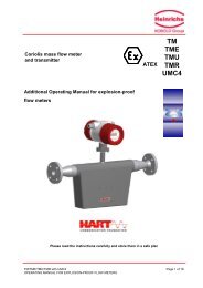
5.3 Mechanical Drawings<br />
5.3.1 Bottom View<br />
5.3.2 Side View<br />
Version 09/04 UME-AGS-CAN Page 33
5.3.3 Front View<br />
5.3.4 Top View<br />
Page 34 UME-AGS-CAN Version 09/04
Installation hints<br />
Both the cable shielding and the metal housings<br />
of encoders and subsequent electronics have a<br />
shielding function. The housing must have the<br />
same potential and be connected to the main<br />
signal ground over the machine chassis or by<br />
means of a separate potential compensating<br />
line. Potential compensating lines should have a<br />
minimum cross section of 6 mm2.<br />
Do not lay signal cable in the direct vicinity of<br />
interference sources (air clearance > 100 mm (4<br />
in.).<br />
6. Models/Ordering Description<br />
Description Typekey<br />
A minimum spacing of 200 mm (8 in.) to<br />
inductors is usually required, for example in<br />
switch-mode power supplies.<br />
Configure the signal lines for minimum length<br />
and avoid the use of intermediate terminals.<br />
In metal cable ducts, sufficient decoupling of<br />
signal lines from interference signal transmitting<br />
cable can usually be achieved with a grounded<br />
partition.<br />
Absolute inclinometer AGS- . . . 2 . . 1 H0 . . . -<br />
Measuring range<br />
Number of axis<br />
005<br />
015<br />
030<br />
Interface CA<br />
Version<br />
Mechanical construction horizontal<br />
Dynamik 2 mPas<br />
Connection connector, 8 pin P8M<br />
1 m cable CRW<br />
Option without -<br />
Tabelle 13 Ordering Description<br />
Version 09/04 UME-AGS-CAN Page 35
6.1 Accessories and documentation<br />
Description Typ<br />
Mating Connector P8F<br />
Cabel Cabel STK 8, 2m, Connector P8F P8F-STK8.2<br />
Cabel STK 8, 5m, Connector P8F P8F-STK8.5<br />
User manual * Installation and configuration manual, german UMD-AGS-CA<br />
User manual * Installation and configuration manual, english UME-AGS-CA<br />
EDS-File * Disc containing EDS-file for configuration DK-AGS-CA<br />
Tabelle 14 Accessories<br />
* These can be downloaded free of charge from our Homepage www.posital.com.<br />
We do not assume responsibility for technical inaccuracies or omissions. Specifications are subject to<br />
change without notice.<br />
7 List of Tables<br />
Tabelle 1 Connector Assignment........................................................................................................................8<br />
Tabelle 2 Overview priority of the CANopen objects............................................................................................10<br />
Tabelle 3 Command description.......................................................................................................................11<br />
Tabelle 4 Data length against command byte.....................................................................................................11<br />
Tabelle 5 General object dictionary...................................................................................................................12<br />
Tabelle 6 Object dictionary according DS301.....................................................................................................12<br />
Tabelle 7 Object dictionary according DS 410....................................................................................................13<br />
Tabelle 8 Nodenumber and baudrate................................................................................................................13<br />
Tabelle 9 Manufacturer specific object dictionary................................................................................................13<br />
Tabelle 10 Electrical data ................................................................................................................................31<br />
Tabelle 11 Mechanical data.............................................................................................................................32<br />
Tabelle 12 Environmantal conditions.................................................................................................................32<br />
Tabelle 13 Ordering Description.......................................................................................................................35<br />
Tabelle 14 Accessories...................................................................................................................................36<br />
Page 36 UME-AGS-CAN Version 09/04