Digital Voltmeter V9648 Measuring
Digital Voltmeter V9648 Measuring Digital Voltmeter V9648 Measuring
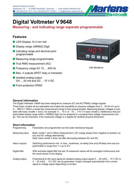
Digital Voltmeter V 9648 Measuring - and indicating range separate programmable Features M LED-Display 14.2 mm red M Display range ±9999(0) Digit M Indicating range and decimal point programmable M Measuring range programmable M True RMS measurement (AC) M Frequency range AC 15 ... 400 Hz M Max. 4 outputs SPDT relay or transistor M Isolated analog output 0/4 ... 20 mA and 0/2 ... 10 V DC M Front protection IP655 General information The Digital Voltmeter V9648 has been designed to measure DC and AC(TRMS) voltage signals. Three basic models all are selectable and makes the possibility to measure voltages from 0... 30.00 mV up to 0 ... 999.9 V. Within a model the measurement range is free programmable. Measuring bipolar voltages is possible with basic models 1 and 2, for example -5 ... +5 V; or -10 ... +10 V in basic model 2. Additional a free programmable display range within ± 9999(0) digit can be assigned to a programmed voltage measurement range. This can be important, if the measured voltage is a degree for another physical dimension. Short information Programming Parameters are programmed via front-side membrane keypad. DIN 96x48mm Measuring input Baisc model 1 and 2 offers measurement ± DC (range always from negative to positive value) and AC voltage alternatively. Note: basic model 3 doos not offer decoupling between AC and DC. Alarm outputs Switching performance min. or max., hysteresis, on-delay time and off-delay time are programmable in range from 1 s up to 9 h. Digital filter With activated digital filter the last 16 measured values will be averaged continuously and the result shown in the display. Analog output Proportional to the input signal an isolated analog output signal 0 ... 20 mA/0 ... 10 V DC or 4 ... 20 mA/2 ... 10 V DC can be generated. Output changed automatically from current signal to voltage signal depending on burden. - 1 -
- Page 2 and 3: Technical data Power supply Supply
- Page 4 and 5: Controls and indicators Description
- Page 6 and 7: Configuration Button Display Descri
- Page 8: Ordering code V9648 - 1. - 2. - 3.
<strong>Digital</strong> <strong>Voltmeter</strong> V 9648<br />
<strong>Measuring</strong> - and indicating range separate programmable<br />
Features<br />
M LED-Display 14.2 mm red<br />
M Display range ±9999(0) Digit<br />
M Indicating range and decimal point<br />
programmable<br />
M <strong>Measuring</strong> range programmable<br />
M True RMS measurement (AC)<br />
M Frequency range AC 15 ... 400 Hz<br />
M Max. 4 outputs SPDT relay or transistor<br />
M Isolated analog output<br />
0/4 ... 20 mA and 0/2 ... 10 V DC<br />
M Front protection IP655<br />
General information<br />
The <strong>Digital</strong> <strong>Voltmeter</strong> <strong>V9648</strong> has been designed to measure DC and AC(TRMS) voltage signals.<br />
Three basic models all are selectable and makes the possibility to measure voltages from 0... 30.00 mV up to<br />
0 ... 999.9 V. Within a model the measurement range is free programmable. <strong>Measuring</strong> bipolar voltages is possible<br />
with basic models 1 and 2, for example -5 ... +5 V; or -10 ... +10 V in basic model 2. Additional a free programmable<br />
display range within ± 9999(0) digit can be assigned to a programmed voltage measurement range.<br />
This can be important, if the measured voltage is a degree for another physical dimension.<br />
Short information<br />
Programming Parameters are programmed via front-side membrane keypad.<br />
DIN 96x48mm<br />
<strong>Measuring</strong> input Baisc model 1 and 2 offers measurement ± DC (range always from negative to positive value)<br />
and AC voltage alternatively.<br />
Note: basic model 3 doos not offer decoupling between AC and DC.<br />
Alarm outputs Switching performance min. or max., hysteresis, on-delay time and off-delay time are programmable<br />
in range from 1 s up to 9 h.<br />
<strong>Digital</strong> filter With activated digital filter the last 16 measured values will be averaged continuously and<br />
the result shown in the display.<br />
Analog output Proportional to the input signal an isolated analog output signal 0 ... 20 mA/0 ... 10 V DC or<br />
4 ... 20 mA/2 ... 10 V DC can be generated. Output changed automatically from current<br />
signal to voltage signal depending on burden.<br />
- 1 -
Technical data<br />
Power supply<br />
Supply voltage : 230 V AC ±10 %; 115 V AC ±10 %, 24 V AC ±10 % or 24 V DC ±15 %<br />
Power consumption : max. 3.5 VA, with analog output 5 VA<br />
Operating temperature : -10 ... +55 °C<br />
Rated voltage : Model 1 + 2; 300 V AC acc. VDE 0110 between input/output/supply voltage<br />
Model 3; 1000 V between input/output, supply voltage<br />
Degree of pollution 2,<br />
Over-voltage category : Model 1 + 2, category III<br />
Model 3, < 600 V category III, > 600 V category II<br />
Test voltage : Model 1 + 2; 4 kV DC between input/output/supply voltage<br />
Model 3, 6 kV between input/output, supply voltage<br />
- conformity : EN55022, EN60555, IEC61000-4-3/4/5/11/13<br />
Input<br />
Input resistance : Model 1 = 130 kOhm, Model 2 = 1.3 MOhm, Model 3 = 2.6 MOhm<br />
Overload : Model 1+2 = 300 V AC/DC; Model 3 = 1200 V AC/DC<br />
Accuracy : < 0.1 % ±2 digit (DC); 0.5 % ±2 digit (AC)<br />
Temperature coefficient : 0.05 %/K<br />
Display : LED red, 14.2 mm<br />
Display range : ±9999(0) digit , leading zero suppression<br />
Parameter display : LED 2-digit red, 7 mm (parameter - and output indicator)<br />
Output<br />
Relay : SPDT < 250 V AC < 250 VA < 2 A, < 300 V DC < 50 W < 2 A<br />
Transistor : max. 35 V AC/DC/100 mA, short circuit protected<br />
Analog output : 0/4 ... 20 mA burden ≤500 Ω; 0/2 ... 10 V burden >500 Ω, isolated<br />
Automatic output changing (burden dependent)<br />
-Accuracy : 0.1 %; TK 0.01 %/K<br />
Case : Panel case DIN 96x48 mm, material PA6-GF; UL94V-0<br />
Dimensions : Front 96x48 mm, mounting depth 100 mm,<br />
Weight : max. 390 g<br />
Electrical connection : Clamp terminals, 2 mm² single wire, 1,5 mm² flexible wire, AWG14<br />
Protection : Front IP65, terminals IP20, fingersafe acc. German BGV A3<br />
Dimensions<br />
Seal<br />
- 2 -<br />
Position terminal strips<br />
Panel cut-out<br />
acc. to DIN 43700-96x48
Connection diagrams<br />
Terminal strip A<br />
Input 0 ... 30 mV/1000 V AC/DC<br />
Terminal strip B (varies with version)<br />
2 alarm outputs<br />
Relay Transistor<br />
Terminal strip C (varies with version)<br />
2 alarm outputs Analog output<br />
Relay Transistor AO<br />
Terminal strip D supply voltage (varies with version)<br />
- 3 -
Controls and indicators<br />
Description<br />
Operating of the device is arranged in 2 levels. The requested parameter can be called by button . For selections<br />
within a parameter or for entering data, use buttons and .<br />
After power-on, the device initializes itself. The display shows the message ����.<br />
After the initializing procedure the device is located in the Working level. Set points of the alarm outputs can<br />
be programmed if they are available.<br />
Pressing the button for more than 2 seconds, activates the Configuration level. Now all the parameters<br />
which defines the function of the panelmeter can be programmed. E.g. the switching performance of the alarm<br />
outputs and the analog output.<br />
After finishing the configuration or when no button was pushed for more than 2 minutes, the program returns to<br />
the working level. Leaving the configuration level is possible at any time by pressing the button for more<br />
than 2 seconds.<br />
Parameter display as status indicator for the alarm outputs A1-A4.<br />
Error codes:<br />
Actual value<br />
Parameter display<br />
or activated<br />
alarm outputs<br />
Segments f (A1/A3) and/or b (A2/A4) are flashing with 2 Hz, if the delay time is active.<br />
Segments e (A1/A3) or c (A2/A4) are output indicators.<br />
Display flashes The input signal is situated around more than 3 % outside of the programmed measuring<br />
range. The A/D- converter is over driving and the display flashes with appr. 1 Hz.<br />
������ EEPROM test. Reading this message, an error has been occurred. When pushing the button<br />
a copy of the EEPROM will be reloaded. The device works with the factory settings.<br />
Is this copy not working, please ship the panelmeter to factory for repair service.<br />
��� Parameter locked. See configuration page 7.<br />
Fixed zero<br />
Field for unit<br />
Parameter button<br />
Down button<br />
Up button<br />
Start-up note: The device has to be configured, before it can be used ⇒ see page 6.<br />
- 4 -<br />
Field for<br />
additional text
Notes to representation<br />
����<br />
�������<br />
�������<br />
���<br />
���<br />
���<br />
����<br />
���<br />
Parameter is only displayed when configurated<br />
Parameter is only displayed when feature is included (see order code)<br />
Please Note: All parameters can be called if they are not blocked by other programmed parameters and if<br />
they are available. Factory settings are shown in the display.<br />
Working level<br />
Button Display Description<br />
Actual value<br />
����<br />
�������<br />
Output indication<br />
(only if installed and activated).<br />
Display brightness<br />
Permanent changing in the working level possible.<br />
Setting possible in 9 steps with buttons and .<br />
Note : only model 1 and 2.<br />
Max. peak reading<br />
Reset with buttons or , and at every power off.<br />
Min. peak reading<br />
Reset with buttons or , and at every power off.<br />
Setpoint output A1<br />
Setting possible from �� ... �� with buttons and .<br />
�� (start value) ... �� (end value)<br />
Note:<br />
Setpoints for alarm outputs A1 ... A4 have to be configured in the same way.<br />
- 5 -
Configuration<br />
Button Display Description (Display graphic shows factory settings)<br />
Press<br />
2 s<br />
1<br />
2<br />
3<br />
4<br />
5<br />
6<br />
7<br />
8<br />
���<br />
��<br />
���<br />
��<br />
��<br />
��<br />
��<br />
��<br />
continue page 7<br />
���<br />
�<br />
���<br />
��� �<br />
��<br />
��<br />
�<br />
��� �<br />
<strong>Digital</strong> filter<br />
��� , �� Averaging of the last 16 measured values continously.<br />
Selection with buttons and .<br />
Display correction<br />
Setting possible from ���(�) ... ��(�) Digit<br />
with buttons and .<br />
Input signal<br />
����� DC voltage unipolar (measuring range 0 ... end value �� , Param. 4)<br />
������� DC voltage bipolar (measuring range e.g. -100 ... +100V)<br />
��� AC voltage TRMS<br />
Selection with buttons and .<br />
<strong>Measuring</strong> range (End value)<br />
Model 1 30.00 ... 4000 mV (floating point)<br />
Model 2 3.000 ... 250.0 V (floating point)<br />
Model 3 200.0 ... 999.9 V<br />
Selection with buttons and .<br />
Fixed zero 0, e.g ����������������+����<br />
�� ; ���<br />
Selection with buttons and .<br />
Decimal places<br />
if �� = �� : �. .� .�� .���<br />
if �� = ��� : �. .�� .��� .����<br />
Selection with buttons and .<br />
Start value for indicating range and analog output.<br />
Setting possible from ����� ... ���� digit with buttons and .<br />
In case of modification a new configuration of the alarm outputs is necessary.<br />
End value for indicating range and analog output.<br />
Setting from ����� ... ���� digit with buttons and .<br />
In case of modification a new configuration of the alarm outputs is necessary.<br />
If ��> ��, the output works with a decreasing characteristic.<br />
- 6 -
Button<br />
9<br />
Display Description (Display graphic shows factory settings)<br />
Switching function alarm output A1<br />
������ � � � ,�� � � (min) ,�� � � (max)<br />
���<br />
If activated the start value will be loaded for set point.<br />
Selection with buttons and .<br />
10<br />
11<br />
���<br />
12<br />
13<br />
14<br />
15<br />
16<br />
���<br />
��<br />
��<br />
�����<br />
���<br />
�����<br />
���<br />
��<br />
��<br />
��<br />
����<br />
��<br />
���<br />
����<br />
�������<br />
Setpoint alarm output A1<br />
Setting possible from �� (start value) ... �� (end value)<br />
with buttons and .<br />
Hysteresis alarm output A1<br />
Setting possible from � ... ����(�) Digit<br />
with buttons and .<br />
Switch-on delay time alarm output A1<br />
Setting possible from �.��.�� ... �.��.�� (h.mm.ss)<br />
with buttons and .<br />
Switch-off delay time alarm output A1<br />
Setting possible from �.��.�� ... �.��.�� (h.mm.ss)<br />
with buttons and .<br />
Note:<br />
The parameter settings for A2 ... A4 have to be configured in the same way.<br />
Analog output<br />
������� mA (0 - 10 V DC)<br />
������� mA (2 - 10 V DC)<br />
The switch-over from current to voltage output is load dependent<br />
(≤ 500 Ω = current output, > 500 Ω = voltage output).<br />
Selection with buttons and .<br />
Code for factory settings<br />
Programming lock<br />
� � �� : no lock<br />
� � � � : configuration level locked<br />
� � � : all parameters locked<br />
Selection with buttons and .<br />
Return to the working level<br />
- 7 -
Ordering code<br />
<strong>V9648</strong> -<br />
1.<br />
-<br />
2.<br />
-<br />
3.<br />
-<br />
1. Terminal strip A<br />
Display range and decimal place free programmable from:<br />
1 0 ... 30.00 mV to 0 ... 4000m V* DC/ACTRMS<br />
2 0 ... 3.000 V to 0 ... 250.0 V* DC/ACTRMS<br />
*(includes e.g. ±5 V, ±10 V )<br />
3 0(5) ... 200.0 V to 0(5) ... 999.9 V DC/ACTRMS<br />
2. Terminal strip B<br />
00<br />
2R<br />
2T<br />
4.<br />
not installed<br />
2 alarm outputs<br />
2 alarm outputs<br />
3. Terminal strip C<br />
00<br />
2R<br />
2T<br />
AO<br />
not installed<br />
2 alarm outputs<br />
2 alarm outputs<br />
Analog output<br />
-<br />
5.<br />
-<br />
relay SPDT<br />
transistor<br />
4. Terminal strip D supply voltage<br />
0 230 V AC ± 10 % 50-60 Hz<br />
1 115 V AC ± 10 % 50-60 Hz<br />
4 24 V AC ± 10 % 50-60 Hz<br />
5 24 V DC ± 15 %<br />
5. Option<br />
00<br />
01<br />
07<br />
without option<br />
min- and max-peak-hold<br />
display brightness programmable, only model 1 and 2<br />
6. Unit (appears in the unit field)<br />
6.<br />
-<br />
7.<br />
relay SPDT<br />
transistor<br />
0/4 ... 20 mA or 0/2 ... 10 V DC<br />
isolated<br />
7. Additional text (will be placed in the field for<br />
additional text, max. 3x90 mm HxW)<br />
- 8 -<br />
01/03-V1.31-01


