6540 SHDSL 2-Wire/4-Wire NTU, AC Powered - Adtran
6540 SHDSL 2-Wire/4-Wire NTU, AC Powered - Adtran
6540 SHDSL 2-Wire/4-Wire NTU, AC Powered - Adtran

You also want an ePaper? Increase the reach of your titles
YUMPU automatically turns print PDFs into web optimized ePapers that Google loves.
*61230001L1-22B*<br />
<strong>6540</strong> <strong>SHDSL</strong> 2-<strong>Wire</strong>/4-<strong>Wire</strong> <strong>NTU</strong>, <strong>AC</strong> <strong>Powered</strong><br />
Express 6500 Series<br />
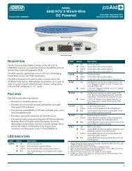
<strong>6540</strong> Front Panel <strong>6540</strong> Rear Panel<br />
DESCRIPTION<br />
The <strong>AC</strong> powered ADTRAN <strong>6540</strong> <strong>SHDSL</strong> 2-<strong>Wire</strong>/4-<strong>Wire</strong> <strong>NTU</strong> (P/N 1230001L1) functions as an<br />
interface between the <strong>SHDSL</strong> network and the Data Terminal Equipment (DTE) for applications such<br />
as LAN-to-LAN bridging, Frame Relay circuit, and PABX termination. The <strong>6540</strong> is designed to be<br />
used either as a remote unit to the ADTRAN Total Access ® 3000 multiservice platform, or as a pair of<br />
units in a point-to-point limited distance campus configuration, with one <strong>6540</strong> configured to “LT”<br />
mode.<br />
COMPLIANCE<br />
EN 300 386-2; IEC 60950/EN 60950/AS NZS60950; S016; S043.2; ITU K.21 Enhanced; Telstra 1555<br />
FEATURES<br />
The <strong>6540</strong> has the following features:<br />
♦ Housed in a standalone plastic case<br />
♦ Provides four front panel recessed pushbuttons, and eight front panel LED indicators<br />
♦ Provides <strong>SHDSL</strong>, G.703, and/or Nx64K ports, and a local management port<br />
♦ Provides a rear panel connection for local <strong>AC</strong> power<br />
♦ Provides bad splice protection using the ADTRAN proprietary Runtime TScan 2.0 splice<br />
protection feature (for more information on this feature and how to locally manage TScan, refer to<br />
the <strong>SHDSL</strong> 2-<strong>Wire</strong>/4-<strong>Wire</strong> <strong>NTU</strong> Product Series Installation and Maintenance Practice, P/N<br />
61230001L1-5)<br />
PUSHBUTTON FUNCTIONALITY<br />
Pushbutton Description<br />
PORT SELECT Press the PORT SELECT button to select the active port. Selection choices cycle through the<br />
following order: No Port, Nx64k, G.703, <strong>SHDSL</strong>.<br />
LOCAL LOOP/<br />
ERR INJ<br />
If a port is selected, and a Bit Error Rate Test (BERT) is not in progress, press the LOCAL<br />
LOOP/ERR INJ button to initiate or terminate a local loop on the selected port. If a BERT is<br />
in progress, press the button to inject a single bit error.<br />
REMOTE LOOP If the <strong>SHDSL</strong> port is selected, press the REMOTE LOOP button to place or remove a remote<br />
loop on the port by sending a EOC request message to the LTU (or <strong>NTU</strong> in campus mode). If<br />
the Nx64K port or G.703 port (with only one service defined) is selected, press this button to<br />
place or remove a remote loop on the selected port's single data service by sending respective<br />
inband loop up or loop down patterns to the far end (in the associated data service timeslots).<br />
BERT If a port is selected and there are no local loops, press the BERT button to start or stop a<br />
BERT on the selected port.<br />
<strong>SHDSL</strong> G.703<br />
LED INDICATOR FUNCTIONALITY<br />
Label Status Description<br />
<strong>SHDSL</strong> �<br />
�<br />
�<br />
�<br />
G.703 �<br />
�<br />
�<br />
�<br />
Nx64K �<br />
�<br />
�<br />
RTS/C �<br />
�<br />
RLSD/I �<br />
Off<br />
Green<br />
Yellow<br />
Red<br />
Off<br />
Green<br />
Yellow<br />
Red<br />
Off<br />
Green<br />
Red<br />
For more information, refer to the Installation and Maintenance Practice (P/N 61230001L1-5) available online at www.adtran.com.<br />
�<br />
LLOOP �<br />
�<br />
�<br />
RLOOP �<br />
�<br />
�<br />
BERT �<br />
�<br />
�<br />
�<br />
Off<br />
Green<br />
Off<br />
Green<br />
Off<br />
Yellow<br />
Red<br />
Off<br />
Yellow<br />
Red<br />
Off<br />
Green<br />
Yellow<br />
Red<br />
V.35/V.36<br />
Nx64K<br />
X.21<br />
CONTROL V.28<br />
Unit is powered off<br />
Port is trained; no active alarms<br />
Port is trained with a minor active alarm (1)<br />
Port is attempting to or is trained with a major alarm (2)<br />
Port is not active<br />
Active Port with no active alarm<br />
Active Port with a minor alarm (3)<br />
Active Port with a major alarm (4)<br />
Port is not active<br />
Active Port with no active alarm<br />
Active Port with an active alarm condition (5)<br />
61230001L1-22B<br />
0612<br />
100-240V<strong>AC</strong> 50/60Hz 100mA<br />
Nx64K port is not active or when active, V.35/V.36 “Request To Send” or X.21<br />
“Control” line from the DTE is off<br />
V.35/V.36 “Request To Send” or X.21 “Control” line from the DTE is on<br />
Nx64K port is inactive or when active, V.35/V.36 “Receive Line Signal Detector” and<br />
X.21 “Indication” control line from the <strong>NTU</strong> is off.<br />
V.35/V.36 “Receive Line Signal Detector” or X.21 “Indication” control line from the<br />
<strong>NTU</strong> (DCE) is on<br />
Local Loop is not active<br />
Active Local Loopback on the selected port<br />
Active Local Loop on one or more ports or services (when no port is selected)<br />
Remote Loop is not active<br />
Active Remote Loopback on the selected port (when determined via established EOC)<br />
Active Remote Loop on one or more ports or services (when no port is selected)<br />
BERT is not active<br />
Active BERT and the test pattern detector is synchronized with no received bit errors<br />
Active BERT and one or more test pattern bit errors have been received<br />
Active BERT but the test pattern detector is not synchronized<br />
1. Minor <strong>SHDSL</strong> port alarms: CRC errors, Loop Attenuation Threshold Alarm, SNR Margin Threshold Alarm, Segment<br />
Anomaly, and any ES, SES, UAS, CVC, and LOSWS 15-Minute Threshold Alarm<br />
2. Major <strong>SHDSL</strong> port alarms: LOS, LOSW, or Segment Defect<br />
3. Minor G.703 port alarms: Rx RAI, Frame Slip, CRC-4 errors, LBER, and any ES, SES, UAS, and CVC 15-Minute<br />
Threshold Alarm<br />
4. Major G.703 port alarms: LOS, LOF, LOMF, Rx AIS, or HBER<br />
5. Nx64K port alarms: Clock Slip, Loss of External Clock, FIFO Underflow/Overflow, and Inactivity Alarm<br />
©2006 ADTRAN, Inc. All<br />
Rights Reserved.
MENU TREE<br />
Main Menu<br />
1. Unit Information<br />
2. Provisioning<br />
3. Status<br />
4. Test<br />
5. Performance History<br />
6. TSCAN<br />
7. Terminal Mode<br />
1. LTU<br />
2. <strong>NTU</strong><br />
1. Unit Options<br />
2. <strong>SHDSL</strong> Options<br />
3. G.703 Options<br />
4. Nx64K Options<br />
5. Test Options<br />
1. <strong>SHDSL</strong> Port<br />
2. G.703 Port<br />
3. G.703 Services<br />
4. Nx64K Port<br />
5. Reset All Status<br />
1. Restart Bad Splice Detector<br />
2. 24 Hour Counts<br />
Local Management<br />
Remote Virtual Terminal Management<br />
<strong>6540</strong> <strong>SHDSL</strong> 2-<strong>Wire</strong>/4-<strong>Wire</strong> <strong>NTU</strong>, <strong>AC</strong> <strong>Powered</strong><br />
1. Interface Mode<br />
2. Payload Rate (kbps) *<br />
3. SNR Margin Alarm Threshold (dB)<br />
4. Loop Attenuation Alarm Threshold (dB)<br />
5. Outage Auto-Retrain<br />
6. PM Thresholds<br />
1. ISDN-PRA V3<br />
2. G.704 CRC-4 Multiframing<br />
3. Timeslot Idle Pattern<br />
4. Spare Bits Insertion to Span<br />
5. Spare Bits Pattern to Span<br />
6. Spare Bits Insertion<br />
7. Spare Bits Pattern<br />
8. RAI Generation<br />
9. E-bit Generation<br />
10. ES 15-Minute Alarm Threshold<br />
11. SES 15-Minute Alarm Threshold<br />
12. UAS 15 Minute Alarm Threshold<br />
13. CVC 15-Minute Alarm Threshold<br />
1. Loopback Types<br />
2. Inband Loopback Options<br />
3. Loopback Timeout (Min)<br />
4. BERT Pattern<br />
5. BERT Pattern Polarity<br />
6. Pushbuttons (All)<br />
7. <strong>SHDSL</strong> Port Select Pushbuttons<br />
8. V.35/V.36 RL (Circuit 140)<br />
9. V.35/V.36 LL (Circuit 141)<br />
10. V.35/V.36 TI (Circuit 142)<br />
1. ES 15-Minute Alarm Threshold<br />
2. SES 15-Minute Alarm Threshold<br />
3. UAS 15-Minute Alarm Threshold<br />
4. CVC 15-Minute Alarm Threshold<br />
5. LOSWS 15-Minute Alarm Threshold<br />
6. OS 15-Minute Alarm Threshold<br />
1. 2-<strong>Wire</strong><br />
2. 4-<strong>Wire</strong><br />
0. Disabled<br />
1-15. Alarm Threshold<br />
0. Disabled<br />
1-127. Alarm Threshold<br />
1. Disabled<br />
2. Enabled<br />
0. Disabled<br />
1-900. Seconds<br />
0. Disabled<br />
1-65535. Seconds<br />
0. Disabled<br />
1-900. Seconds<br />
1. Disabled<br />
2. Enabled<br />
00h to FFh<br />
1. Disabled<br />
2. Enabled<br />
00h to FFh<br />
1. Disabled<br />
2. Enabled<br />
00h to FFh<br />
1. Disabled<br />
2. Enabled<br />
0. Disabled<br />
1-900. Seconds<br />
0. Disabled<br />
1-65535. Seconds<br />
1. Dual Sided<br />
2. Transparent<br />
3. Nontransparent<br />
1. In-band Loopback Protocol<br />
2. G.703 Services In-band Pattern Detection<br />
3. Nx64k In-band Pattern Detection<br />
0. Disabled<br />
1-199. Time Out in Minutes<br />
1. ALT<br />
2. 2047<br />
3. 2E15-1<br />
4. QRSS<br />
1. Normal<br />
2. Inverted<br />
1. Disabled<br />
2. Enabled<br />
1. Permanent Off<br />
2. DTE Driven<br />
1. Permanent Off<br />
2. Test Driven<br />
1. <strong>SHDSL</strong> Port<br />
2. G.703 Port<br />
3. Reset All<br />
1. Unit Mode<br />
2. Cross-Connect Map<br />
3. Clock Source<br />
4. Circuit ID<br />
5. Date and Time<br />
6. Restore Factory Defaults<br />
7. Upgrade Firmware<br />
8. Local Management<br />
9. Change Password<br />
1. Interface Type Auto Detection<br />
2. Interface Type Manual Select<br />
3. Inactivity Alarm Delay (Secs)<br />
4. Tx Clock Source<br />
5. Tx Clock Polarity<br />
6. X.21 C Mode<br />
7. X.21 I Mode<br />
8. V.35/V.36 RTS (Circuit 105)<br />
9. V.35/V.36 RTS (Circuit 106)<br />
10. V.35/V.36 RTS to CTS Delay (ms)<br />
11. V.35/V.36 DSR (Circuit 107)<br />
12. V.35/V.36 DTR (Circuit 108/2)<br />
13. CVC 15-Minute Alarm Threshold<br />
1. PN127<br />
2. V.54<br />
1. Disabled<br />
2. Enabled<br />
1. Disabled<br />
2. Enabled<br />
1. <strong>SHDSL</strong> Local Loopback<br />
2. <strong>SHDSL</strong> Remote Loopback<br />
3. <strong>SHDSL</strong> BERT<br />
4. G.703 Local Loopback<br />
5. G.703 BERT<br />
1. Local Loopback<br />
6. G.703 Services<br />
2. Remote Inband Loopback<br />
3. BERT<br />
7. Nx64k Local Loopback<br />
8. Nx64k Remote Inband Loopback<br />
9. Nx64k BERT<br />
Warranty: ADTRAN will replace or repair this product within the warranty period if it does not meet its published specifications or fails while in service.<br />
Warranty information can be found online at www.adtran.com/warranty.<br />
PRICING AND AVAILABILITY 800.827.0807<br />
TECH SUPPORT 800.726.8663<br />
RETURN FOR REPAIR 256.963.8722<br />
www.adtran.com<br />
61230001L1-22B<br />
1. NT<br />
2. LT<br />
1. Internal Clock<br />
2. Nx64 ETC(113)/X<br />
3. G.703 Rx Clock<br />
4. <strong>SHDSL</strong> Rx Clock<br />
1. Disabled<br />
2. Enabled<br />
1. Disabled<br />
2. Enabled<br />
1. X.21<br />
2. V.35<br />
3. V.36<br />
0. Disabled<br />
1-100. Alarm Threshold<br />
1. From DCE, TC (Circuit 114)<br />
2. From DTE, ETC (Circuit 113)<br />
1. Normal<br />
2. Inverted<br />
3. Auto<br />
1. Permanent On<br />
2. DTE Driven<br />
1. Permanent On<br />
2. Sync Mode<br />
1. Permanent On<br />
2. DTE Driven<br />
1. Permanent Off<br />
2. Permanent On<br />
3. RTS Driven<br />
0 to 255 = Delay in ms<br />
1. Permanent Off<br />
2. Permanent On<br />
1. Permanent On<br />
2. DTE Driven<br />
1. Permanent Off<br />
2. Permanent On<br />
3. Sync Mode<br />
1. Dual Sided<br />
2. Customer Transparent<br />
3. Customer Non-Transparent<br />
4. Network Transparent<br />
5. Network Non-Transparent<br />
* 2-wire mode: 192 kbps to 2.304 Mbps (N x 64 kbps, where N=3 to 36)<br />
4-wire mode: 384 kbps to 4.608 Mbps (N x 64 kbps, where N=even numbers, 6 to 72)