You also want an ePaper? Increase the reach of your titles
YUMPU automatically turns print PDFs into web optimized ePapers that Google loves.
Product P/N: 1230002E1<br />
DESCRIPTION<br />
SHDSL G.703<br />
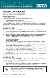
The DC Powered 6540 SHDSL 2/Wire/4-Wire NTU (P/N<br />
1230002E1) functions as an interface between the SHDSL network<br />
and the Data Terminal Equipment (DTE).<br />
The 6540 supports applications such as LAN-to-LAN bridging,<br />
Frame Relay circuit, and PABX termination.<br />
The 6540 is designed to be used as either a remote unit to the<br />
ADTRAN Total Access ® 3000 multiservice platform, or as a pair of<br />
units in a point-to-point limited distance campus configuration,<br />
with one 6540 configured to “LT” mode.<br />
FEATURES<br />
The 6540 has the following features:<br />
• Housed in a standalone plastic case<br />
• Provides four front panel recessed pushbuttons and eight<br />
front panel LED indicators<br />
• Provides rear panel SHDSL, G.703 and/or Nx64K ports, and a<br />
local management port<br />
• Provides a rear panel connection for local DC power<br />
• Provides bad splice protection using the ADTRAN proprietary<br />
Runtime TScan 2.0 splice protection feature (for more<br />
information on this feature and how to locally manage TScan,<br />
refer to the SHDSL 2-Wire/4-Wire NTU Product Series<br />
Installation and Maintenance Guide, P/N 61230001E1-5)<br />
LED INDICATORS<br />
Label Status Description<br />
SHDSL �<br />
�<br />
�<br />
�<br />
Off<br />
Green<br />
Yellow<br />
Red<br />
Unit is powered off<br />
Port is trained; no active alarms<br />
Port is trained with a minor active alarm (1)<br />
Port is attempting to or is trained with a major<br />
alarm (2)<br />
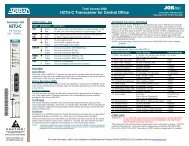
SHDSL<br />
6540 NTU 2-Wire/4-Wire<br />
DC Powered<br />
6540 Front Panel<br />
V.35/V.36<br />
Nx64K<br />
6540 Rear Panel<br />
X.21<br />
CONTROL V.28<br />
G.703 �<br />
�<br />
�<br />
�<br />
NX64K �<br />
�<br />
�<br />
RTS/C �<br />
�<br />
RLSD/I �<br />
�<br />
LLOOP �<br />
�<br />
�<br />
RLOOP �<br />
�<br />
�<br />
BERT �<br />
�<br />
�<br />
�<br />
Off<br />
Green<br />
Yellow<br />
Red<br />
Off<br />
Green<br />
Red<br />
Off<br />
Green<br />
Off<br />
Green<br />
Off<br />
Yellow<br />
Red<br />
Off<br />
Yellow<br />
Red<br />
Off<br />
Green<br />
Yellow<br />
Red<br />
Express 6500 Series<br />
35-80VDC 250mA<br />
NC +<br />
Label Status Description<br />
<strong>jobAid</strong><br />
Issue Date: September 2011<br />
Document P/N: 61230002E1-22D<br />
Port is not active<br />
Active Port with no active alarm<br />
Active Port with a minor alarm (3)<br />
Active Port with a major alarm (4)<br />
Port is not active<br />
Active Port with no active alarm<br />
Active Port with an active alarm condition (5)<br />
Nx64K port is not active or when active, V.35/<br />
V.36 “Request To Send” or X.21 “Control” line<br />
from the DTE is off<br />
V.35/V.36 “Request To Send” or X.21 “Control”<br />
line from the DTE is on<br />
Nx64K port is inactive or when active, V.35/<br />
V.36 “Receive Line Signal Detector” and X.21<br />
“Indication” control line from the NTU is off.<br />
V.35/V.36 “Receive Line Signal Detector” or<br />
X.21 “Indication” control line from the NTU<br />
(DCE) is on<br />
Local Loop is not active<br />
Active Local Loopback on the selected port<br />
Active Local Loop on one or more ports or services<br />
(when no port is selected)<br />
Remote Loop is not active<br />
Active Remote Loopback on the selected port<br />
(when determined via established EOC)<br />
Active Remote Loop on one or more ports or services<br />
(when no port is selected)<br />
BERT is not active<br />
Active BERT and the test pattern detector is synchronized<br />
with no received bit errors<br />
Active BERT and one or more test pattern bit<br />
errors have been received<br />
Active BERT but the test pattern detector is not<br />
synchronized<br />
1. Minor SHDSL port alarms: CRC errors, Loop Attenuation Threshold Alarm, SNR<br />
Margin Threshold Alarm, Segment Anomaly, and any ES, SES, UAS, CVC, and<br />
LOSWS 15-Minute Threshold Alarm<br />
2. Major SHDSL port alarms: LOS, LOSW, or Segment Defect<br />
3. Minor G.703 port alarms: Rx RAI, Frame Slip, CRC-4 errors, LBER, and any ES,<br />
SES, UAS, and CVC 15-Minute Threshold Alarm<br />
4. Major G.703 port alarms: LOS, LOF, LOMF, Rx AIS, or HBER<br />
5. Nx64K port alarms: Clock Slip, Loss of External Clock, FIFO Underflow/Overflow,<br />
and Inactivity Alarm<br />
1
PUSH BUTTONS<br />
Push Button Description<br />
PORT SELECT Press the PORT SELECT button to select the active<br />
port. Selection choices cycle through the following<br />
order: No Port, Nx64k, G.703, SHDSL.<br />
LOCAL LOOP/<br />
ERR INJ<br />
REMOTE<br />
LOOP<br />
MAINTENANCE<br />
If a port is selected, and a Bit Error Rate Test (BERT) is<br />
not in progress, press the LOCAL LOOP/ERR INJ<br />
button to initiate or terminate a local loop on the<br />
selected port. If a BERT is in progress, press the button<br />
to inject a single bit error.<br />
If the SHDSL port is selected, press the REMOTE<br />
LOOP button to place or remove a remote loop on the<br />
port by sending a EOC request message to the LTU<br />
(or NTU in campus mode). If the Nx64K port or G.703<br />
port (with only one service defined) is selected, press<br />
this button to place or remove a remote loop on the<br />
selected port's single data service by sending respective<br />
inband loop up or loop down patterns to the far<br />
end (in the associated data service timeslots).<br />
BERT If a port is selected and there are no local loops, press<br />
the BERT button to start or stop a BERT on the<br />
selected port.<br />
The 6540 does not require routine hardware maintenance for<br />
normal operation. Do not attempt repairs in the field. Repair<br />
services may be obtained by returning the defective unit to<br />
ADTRAN. Refer to the warranty for further information. Field<br />
support for software is provided through upgrade facilities.<br />
SPECIFICATIONS<br />
Specifications for the 6540 are as follows:<br />
• Electrical<br />
♦ Operating Voltage: -48 VDC<br />
♦ Typical Current and Power Consumption:<br />
120 mA, 5.7 W @ -48 VDC<br />
♦ Maximum Current Draw: 200 mA @ 35 – 80 VDC<br />
♦ Maximum Power Consumption: 6.5 watts @ 35 VDC<br />
• Environmental<br />
♦ Operational Temperature Range: –5°C to +55°C<br />
♦ Storage Temperature Range: –40°C to +85°C<br />
♦ Relative Humidity: up to 95%, noncondensing<br />
• Physical<br />
♦ Height: 2.215 inches (5.63 cm)<br />
♦ Width: 9.25 inches (23.5 cm)<br />
♦ Depth: 6.625 inches (16.8 cm)<br />
♦ Weight: Less than 1 pound (0.45 kg)<br />
INDUSTRY STANDARDS COMPLIANCE<br />
The SHDSL 2-Wire/4-Wire NTU interfaces adhere to these<br />
industry standards, either partially or in full:<br />
• SHDSL: ITU-T G.991.2 (12/03 and 2003 amendments) and<br />
G.994.1 (05/03)<br />
• G.703: ITU-T G.703 (10/98), G.704 (10/98), G.706 (4/91), G.732<br />
(11/88), G.775 (10/98), G.784 (1/94), G.797 (3/96), G.821 (8/<br />
96), G.823 (03/93), and G.826 (2/99)<br />
• Nx64K: ITU-T X.21 (09/92), V.35 (10/84), and V.36 (11/88);<br />
and ISO 2593 (1984), 4903 (1991), and 4902 (1980)<br />
SAFETY AND REGULATORY COMPLIANCE<br />
Refer to the Safety and Regulatory Compliance Notice for this<br />
product (P/N 61230002E1-17) for detailed safety and regulatory<br />
information.<br />
Consultez l'avis sur la sécurité et la conformité à la réglementation<br />
pour ce produit (61230002E1-17) pour obtenir des renseignements<br />
détaillés sur la sécurité et la réglementation.<br />
Ausführliche Sicherheits- und regulatorische Informationen sind<br />
in der Konformitätserklärung zur Sicherheit und Einhaltung von<br />
Normen zu diesem Produkt (61230002E1-17) aufgeführt.<br />
2 61230002E1-22D
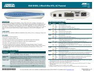
MENU TREE<br />
1. NT<br />
2. LT<br />
1. Internal Clock<br />
2. Nx64 ETC(113)/X<br />
3. G.703 Rx Clock<br />
4. SHDSL Rx Clock<br />
1. Unit Mode<br />
2. Cross-Connect Map<br />
3. Clock Source<br />
4. Circuit ID<br />
5. Date and Time<br />
6. Restore Factory Defaults<br />
7. Upgrade Firmware<br />
8. Local Management<br />
9. Change Password<br />
1. LTU<br />
2. NTU<br />
1. Unit Information<br />
Main Menu<br />
1. Unit Options<br />
1. 2-Wire<br />
2. 4-Wire<br />
2. Provisioning<br />
2. SHDSL Options<br />
1. Disabled<br />
2. Enabled<br />
0. Disabled<br />
1-15. Alarm Threshold<br />
1. Interface Mode<br />
2. Payload Rate (kbps) *<br />
3. SNR Margin Alarm Threshold (dB)<br />
1. Disabled<br />
2. Enabled<br />
1. X.21<br />
2. V.35<br />
3. V.36<br />
0. Disabled<br />
1-100. Alarm Threshold<br />
1. From DCE, TC (Circuit 114)<br />
2. From DTE, ETC (Circuit 113)<br />
1. Normal<br />
2. Inverted<br />
3. Auto<br />
1. Interface Type Auto Detection<br />
0. Disabled<br />
1-127. Alarm Threshold<br />
1. Disabled<br />
2. Enabled<br />
0. Disabled<br />
1-900. Seconds<br />
0. Disabled<br />
1-65535. Seconds<br />
0. Disabled<br />
1-900. Seconds<br />
1. Disabled<br />
2. Enabled<br />
00h to FFh<br />
1. Disabled<br />
2. Enabled<br />
00h to FFh<br />
1. Disabled<br />
2. Enabled<br />
00h to FFh<br />
1. Disabled<br />
2. Enabled<br />
0. Disabled<br />
1-900. Seconds<br />
0. Disabled<br />
1-65535. Seconds<br />
4. Loop Attenuation Alarm Threshold (dB)<br />
2. Interface Type Manual Select<br />
5. Outage Auto-Retrain<br />
3. Inactivity Alarm Delay (Secs)<br />
1. ES 15-Minute Alarm Threshold<br />
2. SES 15-Minute Alarm Threshold<br />
3. UAS 15-Minute Alarm Threshold<br />
4. CVC 15-Minute Alarm Threshold<br />
6. PM Thresholds<br />
4. Tx Clock Source<br />
5. Tx Clock Polarity<br />
5. LOSWS 15-Minute Alarm Threshold<br />
6. OS 15-Minute Alarm Threshold<br />
1. Permanent On<br />
2. DTE Driven<br />
1. ISDN-PRA V3<br />
2. G.704 CRC-4 Multiframing<br />
3. Timeslot Idle Pattern<br />
3. G.703 Options<br />
6. X.21 C Mode<br />
1. Permanent On<br />
2. Sync Mode<br />
7. X.21 I Mode<br />
4. Spare Bits Insertion to Span<br />
5. Spare Bits Pattern to Span<br />
1. Permanent On<br />
2. DTE Driven<br />
8. V.35/V.36 RTS (Circuit 105)<br />
1. Permanent Off<br />
2. Permanent On<br />
3. RTS Driven<br />
0 to 255 = Delay in ms<br />
9. V.35/V.36 RTS (Circuit 106)<br />
6. Spare Bits Insertion<br />
7. Spare Bits Pattern<br />
10. V.35/V.36 RTS to CTS Delay (ms)<br />
1. Permanent Off<br />
2. Permanent On<br />
1. Permanent On<br />
2. DTE Driven<br />
1. Permanent Off<br />
2. Permanent On<br />
3. Sync Mode<br />
11. V.35/V.36 DSR (Circuit 107)<br />
8. RAI Generation<br />
9. E-bit Generation<br />
10. ES 15-Minute Alarm Threshold<br />
11. SES 15-Minute Alarm Threshold<br />
12. UAS 15 Minute Alarm Threshold<br />
13. CVC 15-Minute Alarm Threshold<br />
61230002E1-22D 3<br />
12. V.35/V.36 DTR (Circuit 108/2)<br />
4. Nx64K Options<br />
13. CVC 15-Minute Alarm Threshold<br />
1. Dual Sided<br />
2. Transparent<br />
3. Nontransparent<br />
1. In-band Loopback Protocol<br />
1. Loopback Types<br />
1. PN127<br />
2. V.54<br />
1. Disabled<br />
2. Enabled<br />
1. Disabled<br />
2. Enabled<br />
5. Test Options<br />
2. Inband Loopback Options<br />
2. G.703 Services In-band Pattern Detection<br />
3. Nx64k In-band Pattern Detection<br />
0. Disabled<br />
1-199. Time Out in Minutes<br />
3. Loopback Timeout (Min)<br />
1. ALT<br />
2. 2047<br />
3. 2E15-1<br />
4. BERT Pattern<br />
4. QRSS<br />
1. Dual Sided<br />
2. Customer Transparent<br />
3. Customer Non-Transparent<br />
4. Network Transparent<br />
5. Network Non-Transparent<br />
1. SHDSL Local Loopback<br />
2. SHDSL Remote Loopback<br />
3. SHDSL BERT<br />
4. G.703 Local Loopback<br />
5. G.703 BERT<br />
6. G.703 Services<br />
5. BERT Pattern Polarity<br />
6. Pushbuttons (All)<br />
7. SHDSL Port Select Pushbuttons<br />
1. Local Loopback<br />
2. Remote Inband Loopback<br />
3. BERT<br />
1. Normal<br />
2. Inverted<br />
1. Disabled<br />
2. Enabled<br />
1. Permanent Off<br />
2. DTE Driven<br />
1. Permanent Off<br />
2. Test Driven<br />
8. V.35/V.36 RL (Circuit 140)<br />
9. V.35/V.36 LL (Circuit 141)<br />
3. Status<br />
7. Nx64k Local Loopback<br />
8. Nx64k Remote Inband Loopback<br />
9. Nx64k BERT<br />
10. V.35/V.36 TI (Circuit 142)<br />
1. SHDSL Port<br />
2. G.703 Port<br />
3. G.703 Services<br />
4. Nx64K Port<br />
5. Reset All Status<br />
4. Test<br />
5. Performance History<br />
* 2-wire mode: 192 kbps to 2.304 Mbps (N x 64 kbps, where N=3 to 36)<br />
4-wire mode: 384 kbps to 4.608 Mbps (N x 64 kbps, where N=even numbers, 6 to 72)<br />
1. SHDSL Port<br />
2. G.703 Port<br />
3. Reset All<br />
1. Restart Bad Splice Detector<br />
2. 24 Hour Counts<br />
Local Management<br />
Remote Virtual Terminal Management<br />
6. TSCAN<br />
7. Terminal Mode
For more information, refer to the Installation and Maintenance Guide (P/N 61230001E1-5)<br />
available online at www.adtran.com.<br />
Warranty: ADTRAN will replace or repair this product within the warranty period if it does not<br />
meet its published specifications or fails while in service. Warranty information can be<br />
found online at www.adtran.com/warranty.<br />
©2011 ADTRAN, Inc. All Rights Reserved.<br />
CAUTION!<br />
SUBJECT TO ELECTROSTATIC DAMAGE<br />
OR DECREASE IN RELIABILITY<br />
HANDLING PRECAUTIONS REQUIRED<br />
ADTRAN CUSTOMER CARE:<br />
From within the U.S. 1.800.726.8663<br />
From outside the U.S. +1 256.963.8716<br />
PRICING AND AVAILABILITY 1.800.827.0807<br />
*61230002E1-22D*