TerraBlock Users Guide - Creative Video
TerraBlock Users Guide - Creative Video
TerraBlock Users Guide - Creative Video

Create successful ePaper yourself
Turn your PDF publications into a flip-book with our unique Google optimized e-Paper software.
Version 2.0
TO THE EXTENT ALLOWED BY LOCAL LAW, NEITHER FACILIS TECHNOLOGY NOR ITS THIRD PARTY<br />
SUPPLIERS MAKE ANY OTHER WARRANTY OR CONDITION OF ANY KIND, WHETHER EXPRESS OR<br />
IMPLIED, WITH RESPECT TO THE FACILIS TECHNOLOGY PRODUCTS, AND SPECIFICALLY DISCLAIM THE<br />
IMPLIED WARRANTIES OR CONDITIONS OF MERCHANTABILITY, SATISFACTORY QUALITY, AND FITNESS<br />
FOR A PARTICULAR PURPOSE.<br />
Limitations of Liability<br />
To the extent allowed by local law, the remedies provided in this Warranty Statement are the customer's sole and<br />
exclusive remedies.<br />
TO THE EXTENT ALLOWED BY LOCAL LAW, EXCEPT FOR THE OBLIGATIONS SPECIFICALLY SET FORTH IN THIS<br />
WARRANTY STATEMENT, IN NO EVENT SHALL FACILIS TECHNOLOGY OR ITS THIRD PARTY SUPPLIERS BE LIABLE FOR<br />
DIRECT, INDIRECT, SPECIAL, INCIDENTAL, OR CONSEQUENTIAL DAMAGES, WHETHER BASED ON CONTRACT, TORT,<br />
OR ANY OTHER LEGAL THEORY AND WHETHER ADVISED OF THE POSSIBILITY OF SUCH DAMAGES.<br />
Local Law<br />
This Warranty Statement gives the customer specific legal rights. The customer may also have other rights that vary from<br />
state to state in the United States, from province to province in Canada, and from country to country elsewhere in the<br />
world.<br />
To the extent that this Warranty Statement is inconsistent with local law, this Warranty Statement shall be deemed<br />
modified to be consistent with such local law. Under such local law, certain disclaimers and limitations of this Warranty<br />
Statement may not apply to the customer. For example, some states in the United States, as well as some governments<br />
outside the United States (including provinces in Canada), may:<br />
Preclude the disclaimers and limitations in this Warranty Statement from limiting the statutory rights of a consumer (e.g.,<br />
the United Kingdom);<br />
Otherwise restrict the ability of a manufacturer to enforce such disclaimers or limitations; or Grant the customer<br />
additional warranty rights, specify the duration of implied warranties which the manufacturer cannot disclaim, or not allow<br />
limitations on the duration of implied warranties.<br />
FOR CONSUMER TRANSACTIONS IN AUSTRALIA AND NEW ZEALAND, THE TERMS IN THIS WARRANTY STATEMENT,<br />
EXCEPT TO THE EXTENT LAWFULLY PERMITTED, DO NOT EXCLUDE, RESTRICT, OR MODIFY, AND ARE IN ADDITION<br />
TO, THE MANDATORY STATUTORY RIGHTS APPLICABLE TO THE SALE OF FACILIS TECHNOLOGY PRODUCTS TO SUCH<br />
CUSTOMERS.<br />
Facilis Technology Inc. TERRABLOCK Version 2.0 Setup and <strong>Users</strong> <strong>Guide</strong>, June 2006<br />
2
Contents Page Number<br />
Chapter 1 – Using This <strong>Guide</strong><br />
Who Should Use This <strong>Guide</strong> 05<br />
What This <strong>Guide</strong> Contains<br />
Symbols and Conventions<br />
Documentation Comments<br />
How to Order Printed Copies of this Manual<br />
Chapter 2 – Hardware<br />
Overview 06<br />
Features<br />
Front Panel 07<br />
Control and Indicator Functions<br />
System LEDs<br />
Drive LEDs<br />
System Controls<br />
Enclosure Front Panel Cover 08<br />
Rear Panel<br />
Power Supplies 09<br />
Fans<br />
VGA<br />
Ethernet<br />
Mouse/Keyboard<br />
SATA Controller Slots<br />
Fiber Channel Slots<br />
Mute Button<br />
Chapter 3 – Installation<br />
Before You Begin 10<br />
Mounting the Rack-Mount Enclosure<br />
Installing the Drives 11<br />
Cabling the Enclosure 12<br />
Fiber Channel Cables<br />
Mouse/Keyboard<br />
Monitor<br />
Power Cords<br />
Turning on the Enclosure 13<br />
Connecting a Second <strong>TerraBlock</strong><br />
Adding users to a switch<br />
Chapter 4 – Setup and Administration<br />
System Setup 14<br />
Tools Drive Setup 15<br />
Creating and Managing Volumes 16<br />
<strong>TerraBlock</strong> Manager Columns – Volumes Tab<br />
<strong>TerraBlock</strong> Manager Functions – Volume tab 19<br />
Mount<br />
Unmount<br />
Update ReadOnly<br />
Add <strong>Users</strong> 20<br />
3
Remove Volume<br />
Create Volume<br />
Create Volume Dialogue<br />
Change Volume 21<br />
<strong>Users</strong> Access Permissions 22<br />
Refresh<br />
Formatting Volumes for Use 23<br />
Creating and Managing <strong>Users</strong> 24<br />
<strong>TerraBlock</strong> Manager Columns – <strong>Users</strong> Tab<br />
<strong>TerraBlock</strong> Manager Functions – <strong>Users</strong> tab 25<br />
Create User Dialogue<br />
Add Volumes 26<br />
User Permission – <strong>Users</strong> Tab 27<br />
Chapter 5 – Client Volume Management<br />
Launching The <strong>TerraBlock</strong> Manager 28<br />
Mounting volumes 29<br />
Updating Volumes Manually 30<br />
Updating Volumes with the ROUpdater Utility<br />
Unmounting Volumes 31<br />
Chapter 6 – Workflow for Shared Storage<br />
User Access to Volumes 32<br />
Volume Creation and Allocation<br />
Project Sharing 33<br />
Fiber to Ethernet 34<br />
Chapter 7 – Facilis Migration<br />
Setup and Usage 35<br />
Scanning Volumes and Workspaces 36<br />
Optional Settings<br />
Migration and Verification 37<br />
Appendix A – Additional Setup Tools<br />
SMManager 38<br />
Remote Mounting 41<br />
Tools Drive Configuration<br />
Appendix B – Working with Tandem Volumes<br />
Creating Tandem Volumes 42<br />
Mounting Tandem Volumes 43<br />
Formatting Tandem Volume - Mac 43<br />
Formatting Tandem Volume – Windows 45<br />
Appendix C – Specifications 47<br />
Dimensions and Weight<br />
Environment<br />
Electrical Load<br />
Connectivity<br />
4
Chapter 1 - Using This <strong>Guide</strong><br />
Congratulations on your purchase of the Facilis Technology TERRABLOCK TM . This<br />
product is designed to provide shared storage for video and audio applications requiring<br />
high bandwidth access to active data.<br />
Who Should Use This <strong>Guide</strong><br />
This guide is intended for any user or administrator of the <strong>TerraBlock</strong> system.<br />
What This <strong>Guide</strong> Contains<br />
This guide covers the information you will need to:<br />
• Understand the concept behind the <strong>TerraBlock</strong><br />
• Install the enclosure and drives<br />
• Administrate the volumes and user access<br />
• Use the volume mounting and refresh tool<br />
• Understand the workflow of the <strong>TerraBlock</strong><br />
Symbols and Conventions<br />
� Important Caution or Instruction<br />
� Related Information or Tip<br />
� Checklist<br />
� Description or Definition<br />
Documentation Comments<br />
If you have comments relating to the documentation, please Email<br />
Support@facilistech.com, and specify the page and error or omission in the guide.<br />
How to Order Copies of this Manual<br />
If you’d like a hard copy of this documentation in binder form, please Email<br />
Support@facilistech.com. Include your company name and shipping address.<br />
5
Chapter 2 - Hardware<br />
Overview<br />
The <strong>TerraBlock</strong> is a shared storage system designed for use in the postproduction of<br />
video and audio programming. The features discussed here are designed to facilitate<br />
active collaboration between different editorial rooms within the same facility, or different<br />
editors collaborating on the same project. The <strong>TerraBlock</strong> can also be used as central or<br />
local storage with non-shared workgroups, or with high-bandwidth clients like 1080i HD<br />
edit systems.<br />
Server Features<br />
<strong>TerraBlock</strong> comes standard with 8, 12 or 24 drives, striped for full bandwidth. All of the<br />
drives are hot swappable with automatic recovery of a failed drive.<br />
Some <strong>TerraBlock</strong> systems ship with redundant power supplies. The <strong>TerraBlock</strong> 24D<br />
system can run on 3 power supplies; there are 4 in the base configuration. The<br />
<strong>TerraBlock</strong> 12D system can run on 2 power supplies; there are 3 in the base<br />
configuration.<br />
<strong>TerraBlock</strong> systems ship with between 2 and 5 hot swappable fans, up to two blowers,<br />
and two high-speed fans on the back panel. Any one of these can be disconnected for<br />
any length of time to facilitate replacement.<br />
<strong>TerraBlock</strong> employs the Dyna-RAID protection scheme to protect selected volumes. This<br />
means that if a drive fails, there are other drives holding duplicates of the necessary<br />
files.<br />
• In a mirrored volume, data on one drive is protected by another drive or set of<br />
drives. This means that if an individual drive fails, there is a backup of the<br />
information. The system will then automatically restore data from the mirrored<br />
drive to rebuild the volume.<br />
• In a RAID5 Parity volume, the data is compressed and saved as parity<br />
information. The compression algorithm reduces the space required for<br />
protection of data, to about 9% in Parity Dyna-RAID. When a drive fails, the data<br />
is read in real-time from the parity information.<br />
• In a non-mirrored volume the data is unprotected, so if a drive fails within the<br />
group that hold the volume, that media is lost and will need to be re-captured<br />
from tape, or re-imported from graphics files. The 12D and 8XS servers have one<br />
group, the 24D has two.<br />
� Parity RAID5, while more effective for reducing storage overhead for<br />
protection, is not able to maintain a high performance level when a drive is<br />
missing or failed. Time needed to recover a failed drive also increases. For<br />
uncompressed HD video or multiple uncompressed SD clients, or time critical<br />
projects, consider mirroring for best results. Spanning volumes across drive<br />
groups can help decrease the performance limitations.<br />
6
Front Panel<br />
The front panel of the <strong>TerraBlock</strong> system is used to start up and shut down the unit<br />
and to monitor activity through LED indicators. The drive carriers are inserted in the<br />
front of the unit during initial assembly, or in the event of drive replacement. Software<br />
updates are loaded through the CDROM drive in the front of the unit.<br />
1<br />
2<br />
3<br />
4<br />
5<br />
11<br />
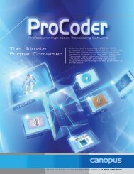
The diagram above shows the 24D enclosure front panel. The 12D unit is similar, with<br />
the control panel at the top. The panel contains the following controls and indicators:<br />
1. Power LED<br />
2. Network LED 1<br />
3. Network LED 2<br />
4. HDD Activity LED<br />
5. Power Supply/Alert LED<br />
6. Power Button<br />
Below is a diagram of the 8xs<br />
1 2 4 6 7 8<br />
o o o o o o<br />
PSU<br />
6<br />
7<br />
o 3<br />
1<br />
8 9<br />
10<br />
7. Reset Button<br />
8. SATA Drive Carrier Handle<br />
9. SATA Drive Power LED<br />
10. SATA Drive Activity LED<br />
11. CDROM Eject Button<br />
Control and Indicator Functions<br />
The following sections describe the front panel<br />
controls and indicators.<br />
System LEDs<br />
The system LEDs provide information about the<br />
status of the enclosure. The LEDs include:<br />
� Power – The Power LED illuminates when the<br />
enclosure is plugged in and started.<br />
� Network – The Network LEDs blink during<br />
activity on either of the Ethernet ports.<br />
� Activity – The Active LED is illuminated when<br />
the internal drive is processing a command.<br />
� Power Supply – The PSU LED illuminates<br />
during failure of a power supply<br />
7
Drive LEDs<br />
Each drive has two LEDs associated with the drive: a Power LED, and an Activity LED.<br />
The LEDs indicate:<br />
� Power — The Power LED is blue when the drive is connected to the enclosure<br />
backplane and has power (except in 8sx enclosure, both LEDs are activity).<br />
� Activity — The Activity LED flashes blue when the drive is processing a<br />
command.<br />
System Controls<br />
The system controls consist of two buttons; a Power switch and Reset switch.<br />
� Power Switch – The Power switch turns the enclosure on and off. The power<br />
switch is on the front of the unit at the top of the indicator panel.<br />
� Reset Switch – The Reset switch resets the system hardware. This should only<br />
be done when instructed by a Facilis technical support representative.<br />
Enclosure Front Panel Cover<br />
The <strong>TerraBlock</strong> drive enclosure has a removable front cover (12D & 24D) that can be kept in<br />
place to prevent access to the drives. The cover is attached via two thumb screws on either side.<br />
Rear Panel<br />
The following sections explain the features of the rear panel of the <strong>TerraBlock</strong> 12D and<br />
24D. The rear panel is the location of the connectivity to the clients, the server data,<br />
interface and monitor ports, power supplies and fans.<br />
1<br />
1<br />
1<br />
4<br />
1<br />
2<br />
2<br />
10 6 6 11 12 12 12 12 11<br />
13 7 7<br />
8 9<br />
10 7 6 7 6 12 11 11 12 12 11<br />
3 4<br />
5 5<br />
3 2 8 1 3 9 2 1 3 2 1 3 2 13<br />
8<br />
4
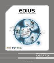
The diagram above shows the 24D and 12D enclosure rear panel. The 8xs rear panel is<br />
very similar to an upright 12D, but without replaceable fans or power supplies, or the<br />
second SATA controller slot (11). The panels contains the following controls and<br />
indicators:<br />
1. PSU Retaining Screw/Clip<br />
2. AC Power Receptacle<br />
3. Removable Power Supply<br />
4. Blower Fan Retaining Screw<br />
5. Removable Blower Fan<br />
6. High-speed Fan Retaining Screw<br />
7. Removable High-speed Fan<br />
* Varies by server motherboard revision<br />
8. VGA Port<br />
9. Ethernet Ports<br />
10. Keyboard/Mouse Ports<br />
11. Internal SATA Controller Slots*<br />
12. External Fiber Channel Slots*<br />
13. Mute Button<br />
Power Supplies – One power supply in both the <strong>TerraBlock</strong> 12D and 24D is redundant<br />
and replaceable while the unit is running. The 24D unit will run as long as at least 3<br />
power supplies are active; the 12D will run with 2 power supplies. The 8xs does not<br />
have a redundant power supply.<br />
Fans – The high-speed fans (and side blower fans in the <strong>TerraBlock</strong> 24D) maintain an<br />
ideal operating temperature within the enclosure. One unit can be removed while the<br />
<strong>TerraBlock</strong> 12d or 24D is running to facilitate replacement.<br />
VGA – The server has the option of being administered locally, or from a fiber-attached<br />
client. The VGA port is available for monitoring the server locally. A standard 15-pin VGA<br />
monitor cable is supported. A VGA monitor is not supplied with the server.<br />
Ethernet – The Ethernet ports are supplied for optional network access to the unit. This<br />
can be useful for controlling the unit via VNC or other remote access applications.<br />
� Running network software on the <strong>TerraBlock</strong> for the purpose of sharing<br />
volumes is not supported. An optional package is available which includes a<br />
dedicated server for Ethernet clients.<br />
Mouse/Keyboard – The mouse/keyboard ports are available for direct control of the<br />
server locally. Standard PS2 mouse and keyboard are supported, but are not included.<br />
SATA Controller Slots – The controller cards for the internal SATA drives use slot 2, 3<br />
and 6 on the 24D, and 2, 6 on the 12, and slot 6 on the 8xs. Slots are numbered starting<br />
from the right if facing the rear of the unit. These slots are unavailable for any other use.<br />
Fiber Channel Slots – The amount and capacity of the fiber channel boards will vary<br />
depending on your configuration. There will be a minimum of 1 board with 2 usable<br />
ports, and a maximum of 3-5 boards with up to 12 usable fiber channel ports. The clients<br />
connect directly to the fiber channel ports via optical fiber.<br />
Mute Button (12D & 24D)– The enclosure sounds an alarm whenever it detects a<br />
power supply failure. The Mute button stops the alarm until the next error occurs.<br />
Pressing the Mute button only silences the alarm—it does not reset the condition that<br />
caused it (see Power Supply LED, this chapter.)<br />
9
Chapter 3 - Installation<br />
This chapter describes how to install and configure your <strong>TerraBlock</strong> shared storage<br />
system. Keep the location of the edit rooms in mind when installing the <strong>TerraBlock</strong>, as<br />
there is a 300meter (984ft) limitation on the length of the multimode fiber in 2Gbit, and<br />
150meter (492ft) limitation in 4Gbit.<br />
Before You Begin<br />
The location of the unit should be cool, clean and vibration-free. Make sure you have all<br />
the components that shipped with the system available at the time of installation. If you<br />
are missing any of the components listed below, do not attempt installation until<br />
speaking with a Facilis customer service representative.<br />
Unpack the <strong>TerraBlock</strong> kit. Check the contents of the kit against the following list to be<br />
sure you have received all the components. The kit contains:<br />
� One <strong>TerraBlock</strong> server enclosure<br />
� One, three, or four power cords<br />
� CDROM of the <strong>TerraBlock</strong> Software and Documentation<br />
� 8, 12 or 24 SATA drives in carriers (shipped separately)<br />
� One spare SATA drive<br />
� A rack-mount kit (optional on 8xs)<br />
� An enclosure front cover (attached on 8xs)<br />
� Qlogic 2Gbit or 4Gbit fiber channel switch (optional)<br />
� ATTO 2Gbit or 4Gbit client fiber channel cards(optional)<br />
� 1U Eserve Bridge server (optional)<br />
Mounting the 12D and 24D Enclosure<br />
The base configuration of the <strong>TerraBlock</strong> system includes rack rails for mounting the<br />
system in a standard 19” rack with rear rails. If you are installing the <strong>TerraBlock</strong><br />
enclosure in a rack (recommended), follow the instructions supplied in the rail kit to<br />
install the rack-mount rails. Be sure that:<br />
� The rails do not interfere with the power strips, power cords, or other<br />
cables at the rear of the rack.<br />
� The rails attach as far forward on the <strong>TerraBlock</strong> enclosure as possible.<br />
� The rails allow the enclosure to slide completely into the rack.<br />
� Do not block power supply vents or otherwise restrict airflow when<br />
installing the unit in a rack.<br />
� Be sure that there is adequate power available within the rack.<br />
� Ensure that a reliable grounding path is maintained within the rack<br />
system. This unit must be connected to Earth ground.<br />
� Mounting the <strong>TerraBlock</strong> enclosure on rack-mount rails is a two-person job!<br />
The enclosure is heavy, and both sides need to be in alignment to fit properly.<br />
If you try to mount the enclosure alone, you might damage it or injure<br />
yourself.<br />
10
Installing the Drives<br />
The <strong>TerraBlock</strong> SATA drives ship separately from the enclosure. They are<br />
installed in drive carriers that fit into the enclosure.<br />
To install the <strong>TerraBlock</strong> SATA drives in the enclosure:<br />
1. Remove a drive carrier assembly from the antistatic bag.<br />
2. Press the latch button on the front of the drive to release the latch. The latch opens to<br />
a 45° angle from the drive carrier.<br />
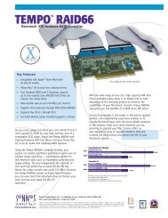
3. Find the label on the drive that specifies the location of the drive in the enclosure. The<br />
numbering is 1-24 (or 1-8/1-12), top-left to bottom-right. Below right is the configuration<br />
of the 24D (and 12D for the first 12 slots), below left is the 8xs setup.<br />
1 2 3 4<br />
5 6 7 8<br />
9 10 11 12<br />
13 14 15 16<br />
17 18 19 20<br />
21 22 23 24<br />
4. Slide the drive carrier assembly into the appropriate slot until the latch makes contact<br />
with the enclosure.<br />
5. Push the latch toward the enclosure to finish sliding the drive and carrier into the<br />
enclosure. You will hear the latch click when the drive and carrier are seated in the slot.<br />
If you encounter resistance do not force the latch closed. Remove the drive and<br />
check the connector and slot for foreign objects.<br />
6. Repeat steps 1 through 5 for all remaining drives.<br />
11<br />
8<br />
7<br />
6<br />
5<br />
4<br />
3<br />
2<br />
1
Cabling the Enclosure<br />
The following describes the process of cabling the <strong>TerraBlock</strong> system.<br />
Fiber Channel Cables<br />
Clients are connected directly to the <strong>TerraBlock</strong> with optical fiber channel cable. The end<br />
connecting to the <strong>TerraBlock</strong> system must have an LC form-factor square termination.<br />
The cable from the client will connect to one of the SFPs on the rear of the <strong>TerraBlock</strong><br />
unit.<br />
� On the 22HX card (dual-port 2Gbit server HBA),<br />
the correct ports to use are the middle (2 & 3)<br />
not the top or bottom (1 & 4). Ports 1 & 4 are<br />
hub ports that connect to ports 2 & 3 respectively,<br />
and are not supported for client connection when<br />
ports 2 & 3 are in use.<br />
A fiber channel cable is comprised of send and receive strands, these must be mated<br />
properly to the send and receive ports on the SFP. If your cable was built as an LC-to-<br />
LC patch cable, the connector should be built to achieve this. If you’re patching through<br />
another cable via a union or patch field, you may have to determine the send and<br />
receive sides.<br />
With the client station powered on and fiber channel card properly installed, place the<br />
other end of the fiber close to a white card in a low light environment, and look for the<br />
laser emitting from one of the ends. Avoid looking directly into the light. That side should<br />
mate to the lower port on the fiber channel SFP. If both lights above the SFP are lit after<br />
fully powered up, the connection is positive.<br />
Mouse/Keyboard<br />
A mouse and keyboard should be installed prior to starting the system. If the mouse and<br />
keyboard are not installed at time of startup, you may have to restart the system to utilize<br />
them once installed.<br />
1. Locate a PS2 mouse and keyboard<br />
2. Locate the proper PS2 port for each by using the symbols on the rear of the unit<br />
3. Plug the PS2 connectors into the proper ports securely<br />
Monitor<br />
A monitor is supported for use directly on the <strong>TerraBlock</strong>, and required for initial setup<br />
and software updates. After initial setup, the monitor may be removed or turned off, as<br />
administration may be performed from any fiber-attached Windows client. To install a<br />
monitor:<br />
1. Locate the VGA port on the rear of the unit. The VGA port is a female 15pin<br />
DIN connector<br />
2. Plug the monitor (not supplied) into the VGA port.<br />
3. Supply power to the monitor, and turn it on.<br />
12
Power Cords<br />
To connect the power cords to the enclosure:<br />
1. Locate the power cords in the <strong>TerraBlock</strong> kit<br />
2. Plug the power cords into the power connectors on the rear of the enclosure<br />
3. Plug the power cord into a power outlet<br />
Turning on the Enclosure<br />
Before turning on the <strong>TerraBlock</strong>, make sure that you have all the drive carriers installed<br />
in the enclosure. You can now turn on the <strong>TerraBlock</strong>.<br />
� If the SATA drives have been left at below 45°F for several hours (a delivery<br />
truck or loading dock), allow the drives to return to room temperature before<br />
inserting and powering on the unit. Drive failure may occur if cold drives are<br />
powered up before warming.<br />
The Power button is on the front indicator panel. Press it once, and the system will<br />
power on. The system has been configured from the factory to login to the operating<br />
system automatically with user account “Facilis” and no password. Upon reaching the<br />
Windows Explorer (desktop), launch the SMDriveMonitor tool shortcut on the desktop.<br />
Wording on the screen that appears should state the service has started.<br />
13
Chapter 4 – Setup and Administration<br />
The <strong>TerraBlock</strong> system has a management tool for creating, changing and removing<br />
volumes, as well as creating, assigning and changing access privilege for users added<br />
to the system. A user with Administrator permissions, or any user that launches the tool<br />
on the server itself, will have the opportunity to add, change and remove volumes, add,<br />
change and remove users, and assign access privilege to users.<br />
System Setup<br />
After the server is installed and powered up, no additional configuration is required. The<br />
software performs striping and disk management internally, and the storage is presented<br />
to the <strong>TerraBlock</strong> Manager application to be allocated into virtual volumes.<br />
When the <strong>TerraBlock</strong> is shipped from the factory, there are no volumes and no users;<br />
these will need to be created. Administrator access is default when the <strong>TerraBlock</strong><br />
Manager is launched on the <strong>TerraBlock</strong> server, and volume/user creation can occur<br />
here. Alternately, after a user with administrator access is created, and that user<br />
matches the name of a fiber channel client OS login, all functions can be accessed from<br />
that attached client. There are three applications that can be launched on the <strong>TerraBlock</strong><br />
server:<br />
• Facilis <strong>TerraBlock</strong> Manager<br />
• SMDriveMonitor<br />
• SMManager<br />
Facilis <strong>TerraBlock</strong> Manager – This is the main tool for both client and administrator<br />
control of the system. Depending on the login of the client, the Manager will display<br />
different information and functions. This is the tool that the administrator will use to<br />
create volumes, users, and assign access and permissions.<br />
� The Facilis <strong>TerraBlock</strong> Manager is launched from Program Files/Facilis<br />
/<strong>TerraBlock</strong>/Manager or the shortcut on the desktop. The name of the<br />
program is <strong>TerraBlock</strong> Manager.exe<br />
SM Drive Monitor – This tool is used to monitor the output of the service during<br />
operation. The Monitor will display the state of the service and the drives included in the<br />
configuration as of launch. The Monitor also displays any errors seen on the drives, and<br />
recovery or protection activity.<br />
� The SM Drive Monitor is launched from Program Files/Facilis/<strong>TerraBlock</strong> or<br />
the shortcut on the desktop. The name of the program is SMDriveMonito.exe<br />
SM Manager – The SM Manager tool is a command-line interface for administration and<br />
management of volumes. All of the <strong>TerraBlock</strong> Manager functions exist in SM Manager,<br />
plus the ability to remotely mount and remove volumes. (See Appendix A: Additional<br />
Setup Tools for more information)<br />
� The SM Manager is launched from Program Files/Facilis/<strong>TerraBlock</strong>/Utilities.<br />
The name of the program is SMManager.exe<br />
14
Tools Volume Setup<br />
The Tools volume is used to distribute system applications to all the client stations, by<br />
using a Read-Only volume that is mounted by default on every connected system. Every<br />
client will have access to the software tools without the need to run an installer.<br />
The <strong>TerraBlock</strong> Manager application is installed onto the Tools volume as a part of the<br />
factory configuration. There will be Windows and Mac directories, all of which contain the<br />
respective versions of the Facilis <strong>TerraBlock</strong> Manager application.<br />
� The Tools volume will not appear on the <strong>TerraBlock</strong> server itself. Instead,<br />
launch from Program Files/Facilis/<strong>TerraBlock</strong>/, or the shortcut on the<br />
desktop.<br />
The Tools volume (named “Tools” by default in the system software), is the first 1GB<br />
volume on the first group of drives in each <strong>TerraBlock</strong> system. Tools is preset to be a<br />
Read-Only volume on every client that connects over fiber channel. The format of the<br />
volume will be FAT32. The reason for using FAT32 is Mac OSX and Windows crossplatform<br />
compatibility. HFS+ (Mac OS Extended) could be used in an all Mac-based<br />
environment, and is required when Mac OS9 clients are involved.<br />
If there is more than one server attached on the Facilis network, there will be a separate<br />
Tools volume for each server. For Mac environments, the name of each Tools volume<br />
must be different, and follow the convention: Tools; Tools1; Tools2; Tools3. If the correct<br />
name wasn’t entered at time of shipment, the Tools volume will require renaming.<br />
An Administrator can change the Tools volume format after installation or add new<br />
versions of the <strong>TerraBlock</strong> manager software to the Tools volume from a fiber-attached<br />
client. See Appendix A: Additional Setup Tools for more information.<br />
� For Mac OS9 clients, each Tools volume must be HFS+ formatted, and the<br />
format utility must be ATTO ExpressPro-Tools 2.8, which is included in the<br />
system packaging. The default settings should be chosen when formatting.<br />
� After formatting, the Tools volume must be made Write-access on a Mac client<br />
before the <strong>TerraBlock</strong> Manager is launched for the first time.<br />
� If HFS is chosen for the Tools volume format, MacDrive TM or similar utility can<br />
be used to mount the volume on a Windows system and access the contents.<br />
However, Windows systems may still launch a copy of the Manager application<br />
from the Windows explorer without access to the Tools volume contents.<br />
15
Creating and Managing Volumes<br />
The <strong>TerraBlock</strong> Manager is used to create and change volumes and users, assign<br />
volumes to users, mount, unmount and update. These examples show the Mac OSX<br />
Manager. The Mac OS9, Windows 2000 and XP versions are identical in functionality.<br />
Mac <strong>TerraBlock</strong> Manager Volumes Tab– Administration Mode<br />
<strong>TerraBlock</strong> Manager Columns – Volume Tab<br />
Name – This is the name of the volume as given by the administrator at time of creation.<br />
It is not the same as the formatted name of the volume, which is specified at the time of<br />
format by a user or administrator on a client workstation. For proper tracking of<br />
volumes and the successful dismounting of volumes on Mac workstations, the<br />
formatted name must exactly match the <strong>TerraBlock</strong> system volume name.<br />
Current User (“G5” above) – The current mount state of a volume on the local client<br />
system.<br />
� W This indicates the volume in that row is mounted on the local station<br />
with write access, and cannot be mounted again with write access, but can<br />
be mounted for ReadOnly access elsewhere.<br />
� R This indicates the volume in that row is mounted on the local client<br />
station with ReadOnly access, and is free to be mounted with any access<br />
elsewhere.<br />
� - (dash) This indicates the volume in that row has not been mounted by<br />
the local station, and is free to be mounted with any access elsewhere.<br />
16
Sys (System) – The current mounted state of a volume across the entire network.<br />
� W This indicates the volume in that row is mounted on some client<br />
station with write access, and cannot be mounted again with write access.<br />
� R This indicates the volume in that row is mounted on some client station<br />
with ReadOnly access, and is free to be mounted with any access.<br />
� - (dash) This indicates the volume in that row has not been mounted by<br />
any station on the network, and is free to be mounted with any access.<br />
State – The state of a volume is related to the drives that comprise the volume. The<br />
possible states are “OK”; “FAIL”; “DAMAGED”; “RECOVERING”.<br />
� OK means that the drives that comprise the volume are all present and<br />
working. This state will exist normally, or after a drive recovery is complete.<br />
� FAIL indicates that a drive in the group that comprises the volume has<br />
failed, and the volume has been actively used since the drive failure was<br />
recorded. If the volume is protected, the state will return to OK once the<br />
volume recovery is complete.<br />
� DAMAGED indicates multiple failures have occurred on a single drive<br />
group. This is very rare, and normally drives can be re-activated and data<br />
salvaged. The volume designation will continue to be “Damaged” as there is<br />
no way to tell if the volume was permanently damaged during the failures.<br />
� RECOVERING indicates that a drive in the group had failed and was<br />
reactivated or replaced. A protected volume will show “recovering” while the<br />
recovery process is active and the drive set is being repaired.<br />
Size – The size of the volume given at the time of creation by the administrator. The<br />
volume must be maintained at that size during and after format, and not partitioned into<br />
smaller volumes at the client. Since the drive size cannot change after creation, consider<br />
creating smaller volumes and adding more volumes when additional space is required.<br />
Group – The group column is related to the group of drives used to create the volume<br />
on the respective server. The column value will be either 1 or 2. This number applies to<br />
each group of 12 drives, or the one group of 8 drives on the 8XS.<br />
1 2 3 4<br />
5 6 7 8<br />
9 10 11 12<br />
13 14 15 16<br />
17 18 19 20<br />
21 22 23 24<br />
} Group 1 � mirror<br />
} Group 2 �mirror<br />
17
In a 24D unit, a mirrored volume spans 2 groups. A non-mirrored or RAID5 volume<br />
spans one group, with parity data on the alternate group in RAID5. A mirrored volume<br />
created on group 1 will use group 2 for its mirror; a group 2 volume uses group 1. To<br />
create a mirrored volume on a given group, the alternate group must have enough free<br />
space available as well. On the 12D and 8xs units, the mirror occurs within the same 8<br />
or 12 drive group, so remaining space must be 2 x the intended capacity of the volume.<br />
To create a RAID5 volume on a given group, that group must have enough remaining<br />
space for the capacity of the volume, plus 9% of the capacity of the volume. On a 24D,<br />
9% must be available on the alternate group.<br />
Dyna-RAID – The designations of “Mirror”; “RAID5” or “----“ are listed for each volume,<br />
according to the state of protection on the volume. This represents the current state of<br />
protection, but any volume can be changed from any state to any other state without<br />
loosing data. In the case of a drive failure, “RAID5” and “Mirror” will maintain data<br />
integrity.<br />
� Mirror indicates that the volume is being mirrored. Every file written to a<br />
disk drive is written again to another drive and on a failure the necessary<br />
mirror data takes over. A volume may be mirrored when created, and the<br />
protection state changed later.<br />
� RAID5 indicates that the volume is being protected parity RAID5.<br />
Information about the primary data is calculated and compressed into<br />
1/12 th the size of the primary data, and saved back onto the drive set. On<br />
a drive failure the necessary RAID5 data is decompressed and used in<br />
place of the missing primary data. A volume may be RAID5 when<br />
created, and the protection state changed later.<br />
� ---- indicates that the volume is not protected. A volume may be RAID5<br />
when created, and the protection state changed later. This column<br />
reflects the current state.<br />
� Parity RAID5, while more effective for reducing storage overhead for<br />
protection, is not able to maintain as high a performance level when a drive is<br />
missing or failed. Time to recover a failed drive is also lengthened. For<br />
uncompressed HD video or multiple uncompressed SD clients, or time critical<br />
projects, consider mirroring for best results. Spanning volumes across drive<br />
groups can help decrease the performance limitation.<br />
Server – Multiple servers can be employed to increase capacity and bandwidth in a<br />
Facilis network. The names of the servers will be displayed here for ease of volume<br />
location.<br />
18
<strong>TerraBlock</strong> Manager Functions – Volume Tab<br />
Mount – When the Mount button is clicked, any volume highlighted in the Volume pane<br />
will be mounted on the local system. If the user has Write access to the volume, a<br />
dialogue will appear asking if the user would like to mount the volume with Write access.<br />
Be careful to ensure you have write permissions for all volumes if requesting multiple<br />
volumes simultaneously with write permissions.<br />
If using a newer ATTO Celerity fiber channel HBA on Mac OS 10.3 and above, Mount<br />
will initiate a rescan of the fiber channel bus, and ask that any applications using the<br />
volumes be closed. However, it is not necessary for all types of applications to be<br />
closed. Please call Facilis customer support for more information.<br />
� The first user to mount a volume after it has been created must have Write<br />
access. Any volume must be formatted on a client station before use.<br />
� The Mount command in the <strong>TerraBlock</strong> Manager must be followed by another<br />
volume mount command from a drive utility in OS9, or by a reboot in OSX when<br />
using a EPCI 3300 ATTO HBA. The volumes may not appear on the desktop<br />
without this second step.<br />
Unmount – The Unmount button will remove any selected volume from the user’s<br />
desktop. If the volume had been mounted with Write access, Unmount will make the<br />
volume available for mounting with write access on other workstations which also have<br />
Write permissions.<br />
� Mac OS 9 and OS 10 require that the formatted name be the exact same as the<br />
volume name in <strong>TerraBlock</strong> Manager. This allows the Unmount, Eject and<br />
Update ReadOnly commands to find the drive when prompted.<br />
� The Unmount command will cause Windows 2000 to display an error. Click OK<br />
and disregard the error.<br />
Update Read-Only – This button is used for workstations that have Read-Only access<br />
to a volume, and need to use data that may have been written to the volume since it was<br />
first mounted on their system. This action will refresh the directories on the ReadOnly<br />
drives, and present the latest version of the data to the Read-Only client.<br />
On Mac systems, you will see this dialogue:<br />
Select “OK” after you see all updated volumes re-appear on the desktop.<br />
19
Add <strong>Users</strong> – This button allows an<br />
administrator to add users to a volume,<br />
with Read-Only or Write permissions.<br />
� Many users can be given Write<br />
permissions to a volume, but only<br />
the first user to mount the volume<br />
as writeable will have that access.<br />
Add User Dialogue<br />
Create Volume Dialogue<br />
This dialogue is used to create new virtual volumes on the system. The volumes created<br />
are allocations of the entire set of storage, but do not affect other volumes on the system<br />
when created. Size of a volume can be 1GB to 2047GB for basic or 2GB to 2046 for a<br />
Tandem volume. On the 24D, the volumes can be created on either of 2 groups (the<br />
emptiest is chosen by default). See “Group” in <strong>TerraBlock</strong> Manager Columns – Volume<br />
Tab.<br />
� Tandem – This selection allows the<br />
administrator to specify multiple<br />
groups instead of a single group for<br />
creation of the full volume size. For<br />
additional information on the<br />
Tandem feature see Appendix B:<br />
Working with Tandem Volumes.<br />
� Dyna-RAID – This selection<br />
allows for the designation of<br />
protection type on a per-volume<br />
basis. The button indicates the<br />
protection type; Mirror, RAID5 or<br />
Unprotected. See <strong>TerraBlock</strong><br />
Manager Columns – Dyna-RAID<br />
for more information.<br />
� Add All <strong>Users</strong>... – This option<br />
automatically adds all known<br />
users to the volume with write<br />
permissions.<br />
Create Volume Dialogue<br />
� When specifying a size for a mirrored volume, be sure to check the remaining space on the<br />
current group as well as the mirror group.<br />
20
� When labeling the volume on the client system at the time of format, you<br />
must use a volume label that exactly matches the volume name.<br />
� In Windows Disk Manager, use the “Properties” of a volume to<br />
determine the volume name when it is mounted on the system. The<br />
Facilis volume name will be displayed with “Hardware Vendor”<br />
� In Mac OSX Disk Utility, the Facilis volume name is located in “Disk<br />
Description”.<br />
� In Mac OS9 drive utilities, the Facilis volume name can be found in<br />
Device Information (usually Apple-I).<br />
� Caution: When naming a virtual volume, use only 11 characters if the volume<br />
will be formatted on a Windows XP platform. Use up to 16 for Mac volumes.<br />
Change Volume – After the virtual volume is created, protected and formatted, there is<br />
the option to change the Name, and protection level of the volume. The name change<br />
will only affect the <strong>TerraBlock</strong> Manager display, not the formatted label on the client<br />
station. Because of this, it is necessary to follow up any change in volume name with a<br />
volume label change on a client with Write access.<br />
Change Volume Dialogue<br />
When changing protection level, the volume must be unmounted from all client<br />
workstations, and depending on the direction of the change, the volume may remain<br />
21
available only for ReadOnly for the duration of the action. This could take several hours<br />
for very large volumes. See the matrix below for more information.<br />
From ↓ To → Unprotected RAID5 Mirror<br />
Unprotected ---- Online Online<br />
RAID5 Immediate ---- ReadOnly<br />
Mirror Immediate ReadOnly Online<br />
User Access Permissions– The User Access Permissions pane within the Volumes tab<br />
allows a user to view and allows the administrator to change which users have access to<br />
a volume, and what permissions the user is allowed. This window also displays the<br />
current state of the volume on each user with permissions.<br />
(+) Signifies that user has the volume mounted with write<br />
access. (-) Signifies that user has the volume mounted with<br />
Read access. On Windows <strong>TerraBlock</strong> Manager, write and<br />
read access is also displayed by bold and italic user name<br />
text, respectively.<br />
The Administrator can remove a user from a volume, or<br />
change the permissions for a user on a certain volume, by<br />
selecting the user and choosing either “Change Permission”<br />
or “Remove from Volume”.<br />
Refresh – The Refresh button is only used to update the display of the <strong>TerraBlock</strong><br />
Manager. The display does not refresh automatically until relaunched, so the Manager<br />
information may become out of sync. Refresh the tool often to ensure accurate data.<br />
22
Formatting Volumes for Use<br />
After creation of volumes and assignment of users, the volumes are ready to be<br />
formatted for use by the operating systems(s) that will be accessing them. The<br />
<strong>TerraBlock</strong> system supports all native drive formats for Windows and Mac.<br />
Once the volume has been assigned to a user, the administrator must format the volume<br />
from a fiber-attached client. This client system must have a user account that coincides<br />
with a user account name in <strong>TerraBlock</strong>. In Windows and Mac OS 10, the account<br />
should be the same as the OS log-in name (Long name in OSX). In Mac OS 9, the<br />
account should be the same as the Owner Name in File Sharing Control Panel.<br />
� In order to format a volume on a client station, that client must be given Write<br />
permission to the volume.<br />
After launching the Facilis <strong>TerraBlock</strong> Manager on the client system, the volumes<br />
assigned to the local user should appear. Select the volume and click Mount, and click<br />
Yes when the application asks to mount with Write permission. The volume can now be<br />
formatted using the following applications:<br />
Windows Macintosh OSX Macintosh OS9<br />
Disk Management Disk Utility ATTO Express Pro-Tools<br />
Avid Drive Utility<br />
� When naming the volume on the client system at time of format, you<br />
must use a volume label that matches the <strong>TerraBlock</strong> volume name.<br />
� Never upgrade a volume to a “Dynamic disk” on Windows.<br />
<strong>TerraBlock</strong> does not support drive striping or Dynamic disks on<br />
any system.<br />
If mounting and using Tandem spanned volumes, please read Appendix B: Working with<br />
Tandem Volumes.<br />
23
Creating and Managing <strong>Users</strong><br />
The Administrator can create users based on OS login, manage the users’ access to<br />
volumes and determine which user login(s) can be given access to administrative<br />
functions. The user tab is only available to a user who has been given administrator<br />
access to change user accounts.<br />
<strong>TerraBlock</strong> Manager <strong>Users</strong> Tab– Administration Mode<br />
In the example above, you see user Name (G5); user’s computer Hostname; World-<br />
Wide Name of the fiber card in the host; Port designation on the <strong>TerraBlock</strong>, and user<br />
Access privilege.<br />
<strong>TerraBlock</strong> Manager Columns – <strong>Users</strong> Tab<br />
The User tab on the <strong>TerraBlock</strong> Manager will only be visible if the local user has “Admin”<br />
access. These are the columns in the <strong>TerraBlock</strong> Manager <strong>Users</strong> Tab:<br />
Name – This is the name of the user as given by the administrator at time of creation.<br />
The name here is the actual user name as reported by the operating system, thus it is<br />
case sensitive to the name seen in the user management utility or preference. On OS9,<br />
the user name will not be a log-in name since there is no log in name, but instead will be<br />
the exact user name seen in the File Sharing control panel.<br />
Hostname – The name given to the computer on which the user is logged in.<br />
Hostnames must be unique to avoid incorrect information being viewed on the Manager<br />
Volume tab.<br />
WWN – The World-Wide-Name is one of the ways Facilis protects the users from<br />
mounting the same volumes with Write access in several places. Every fiber channel<br />
card has a unique WWN. The WWN Index is also used to mount volumes remotely<br />
through the SMManager utility when launched on the <strong>TerraBlock</strong> server.<br />
24
Port – The Port designation specifies the location of the system on the rear of the<br />
<strong>TerraBlock</strong> server. If using a switch, several users may share the same port.<br />
Access – User access is determined by the administrator, and will have 2 states:<br />
� Admin – A user may be granted Administrator access to create and remove<br />
volumes, and create and remove users. Only an Admin will see the User tab on<br />
the <strong>TerraBlock</strong> Manager tool.<br />
� Normal – A user is defaulted to Normal. Normal users will see only the volumes<br />
they were given either read or Write access to, and will have the option to mount,<br />
unmount, or update Read-Only volumes.<br />
<strong>TerraBlock</strong> Manager Functions – User Tab<br />
Create User – This function is used to create a user account for a <strong>TerraBlock</strong> client. The<br />
window appears as below:<br />
Create User Dialogue<br />
User Name – This is the name that the user will use on log in to an operating system<br />
account on the client. This must be exactly the same name in the account properties.<br />
� If a user has not been created but can launch the <strong>TerraBlock</strong> Manager, select<br />
the Tools drive and “Mount”. This will report the user name to the <strong>TerraBlock</strong><br />
server, and it will appear in the Admin User tab after refresh.<br />
Administrator – The Administrator check box allows any user to be given the right to<br />
see every volume, as well as create and remove volumes and users. It is not<br />
recommended that large numbers of users have Administrator access level, as the<br />
amount of volumes may become difficult to sort.<br />
� After a user is created, an Administrator can change the access level of that<br />
user at any time.<br />
25
Remove User – <strong>Users</strong> can be removed from the system with this function.<br />
Copy User – An individual user’s attributes can be copied to a new user. For example,<br />
a user on second shift needs their own unique user name for billing purposes, but needs<br />
identical access privileges to their colleague on first shift. Copy User will duplicate the<br />
attributes of the user highlighted in the User pane, and will prompt for a new user name.<br />
If the name given already exists, the existing user account will be appended with the<br />
new access.<br />
Change Access – <strong>Users</strong> can be assigned Admin or Normal permissions after being<br />
created. It is recommended to have as few Admin accounts as possible to avoid access<br />
to volume creation and deletion.<br />
Add Volumes – Volumes can be added to users, just as users can be added to volumes<br />
in the volumes tab. The window appears as below:<br />
Add Volumes Dialogue<br />
When a volume is added, the selected user will<br />
have either Read-Only (Default) or Write access to<br />
the volume (if the Write Permission box is<br />
checked). Several volumes can be added<br />
simultaneously, but they will all be given the same<br />
access permissions. Access permissions can be<br />
changed after volumes are added by using the<br />
“Change Permission…” button under the Volume<br />
pane in the User tab.<br />
Refresh – The Refresh button is used to update the display of the <strong>TerraBlock</strong> Manager.<br />
The display does not refresh automatically until relaunched, so the displayed information<br />
may become out of sync. Refresh the tool to ensure accurate data before managing<br />
volumes<br />
26
User Permission – User Tab<br />
The volume pane in the user tab allows an administrator to add volumes to users, and<br />
change users’ permissions to volumes.<br />
Change Permissions – This feature allows an administrator to change a user’s<br />
read/write permissions to one volume or many.<br />
Remove from User – Volume permissions can be removed from a user. The user will<br />
no longer have the ability to mount the selected volume(s).<br />
Volumes Pane in User Tab<br />
27
Chapter 5 – Client Volume Management<br />
The <strong>TerraBlock</strong> system allows users to mount and unmount volumes locally via the<br />
<strong>TerraBlock</strong> Manager. This will provide a step-by-step procedure for creating, mounting,<br />
and managing volumes.<br />
Launching the <strong>TerraBlock</strong> Manager<br />
<strong>TerraBlock</strong> Manager can be launched from the Tools volume, or the folder can be copied<br />
and launched from another location on the client. The Tools drive is accessible from<br />
every connected client, and contains an application for each operating system<br />
supported. If you’re on a Windows, OS9 or OSX system, find your version of the<br />
Manager in its respective folder on the Tools drive.<br />
� Macintosh OS 9 systems require an HFS formatted Tools drive, and the drive<br />
must be formatted with ATTOExpressPro-Tools Utility. (See “Tools Volume<br />
Setup” for details)<br />
� Mac OSX systems using ATTO Celerity cards should copy the Manager software<br />
locally, as the bus rescan will cause errors if the Manager is being run from the<br />
fiber-attached drive.<br />
Launch the Facilis <strong>TerraBlock</strong> Manager from the Tools drive or the location of the folder<br />
on the client system. If the client is connected to the <strong>TerraBlock</strong> system correctly, the<br />
<strong>TerraBlock</strong> Manager window will populate with the volumes that have been allocated to<br />
the local user. If only the Tools drive shows in the <strong>TerraBlock</strong> Manager, there may not be<br />
any volumes allocated to your user, or the user name may be incorrect.<br />
� If a user’s name is incorrect (user name is case sensitive), select the Tools<br />
drive and “Mount”. This will report the user name to the <strong>TerraBlock</strong> server,<br />
and it will appear in the Admin User tab after refresh.<br />
<strong>TerraBlock</strong> Manager in Normal user mode:<br />
<strong>TerraBlock</strong> Manager Volume Tab– Normal Mode<br />
For a full explanation of columns and functions in the <strong>TerraBlock</strong> Manager, see “<strong>TerraBlock</strong><br />
Manager Columns – Volume Tab” and “<strong>TerraBlock</strong> Manager Functions – User Tab”.<br />
28
Mounting Volumes<br />
Facilis <strong>TerraBlock</strong> Manager is used to mount and unmount local volumes on a client<br />
system. When the tool is launched, volumes that have been allocated to the local user<br />
will appear. When a volume is selected, the local user’s permissions to the volume are<br />
displayed in the user pane, as well as other users who have permissions to the volume.<br />
User Pane on Volume<br />
Tab in Normal Mode<br />
In this example, G5 shows up with W+ in the user pane,<br />
signifying that G5 has Write permission (W) and has<br />
mounted the volume with Write access (+). The<br />
Scratch2 user has R- signifying that Scratch2 has<br />
ReadOnly permission (R) and has mounted the volume<br />
with ReadOnly access(-).<br />
The FinalCut and Cyclone users have ReadOnly and<br />
Write permissions but have not mounted the volume.<br />
� If a user has mounted a volume with Write<br />
permission, no other user can write to that volume.<br />
The user with Write permission to the volume must<br />
first unmount it to permit another user to write to<br />
that volume. The first user may then re-mount the<br />
volume as Read-Only and access the data.<br />
To mount a volume, select the volume and click Mount. If you have been given Write<br />
access the volume, the system will ask whether you’d like to mount the volume with<br />
Write permission.<br />
If you will be writing to this volume,<br />
select Yes. If you only need to read the<br />
contents of the volume, or another<br />
station will require write access to the<br />
volume, select No. If selecting No for<br />
ReadOnly, there will be a secondary<br />
dialogue on OSX systems.<br />
In the secondary ReadOnly Dialogue,<br />
selecting Yes (preferred for most<br />
applications) will produce a locked<br />
volume that does not require ReadOnly<br />
setting in the Mac OS. If selecting No<br />
(required for few applications), the<br />
volume will have a ReadOnly attribute<br />
set in the Mac OS.<br />
On Mac OSX with a Celerity fiber channel card, a third dialogue may ask you to be sure<br />
all applications using the <strong>TerraBlock</strong> volumes are closed, because the ATTO card will be<br />
rescanned, and this requires all volumes to be ejected temporarily. In Mac OSX, select<br />
29
OK in the final dialogue presented when the volumes appear on the desktop. If any<br />
volumes fail to appear on the Mac desktop or in Windows “My Computer”, the volume<br />
may need to be formatted. See Chapter 4 – Setup and Administration for details.<br />
Updating Volumes Manually<br />
Once a user has mounted a Read-Only volume, data written to the volume by another<br />
user is not visible without an update. This is because the system reads a “snapshot” of<br />
the Read-Only volume created at time it is mounted. The “Update ReadOnly” button will<br />
update this “snapshot”.<br />
� Caution: Read-Only volumes on Windows 2000 and Mac OS 9 will appear to<br />
accept a small amount of data until the volume is refreshed. The data is not<br />
actually written to the volume; the OS may require an Update of a volume that<br />
has been written to accidentally.<br />
Updating Windows Volumes with ROUpdater Utility<br />
On Windows clients that need to see updated views of ReadOnly volumes, there is a<br />
utility that allows a user to set a time interval on updates to all NTFS or FAT32 ReadOnly<br />
volumes. The application is called SMUpdate, and upon launching on a Windows XP<br />
system will update all ReadOnly drives every 15 minutes by default.<br />
If a different interval is desired, ROUpdater can also be launched interactively through<br />
use of the CMD application (DOS shell). By navigating in CMD to the location of<br />
RoUpdater.exe, the user may launch the application with a different timing interval.<br />
ROUpdater Application in Interactive Mode<br />
30
All standard Facilis ReadOnly volumes will be updated, if a Tandem volume is mounted<br />
as ReadOnly, a special case allows for the drive letter of the Tandem volume to be<br />
entered. In the case above, the ROUpdater was copied into the root level of the C: drive.<br />
Using the command prompt, the ROUpdater was set to 60 minute intervals, and drive<br />
letter J: was specified as the Tandem ReadOnly volume. The proper usage of the<br />
argument is . If no time interval is specified, default of 15 minutes will be<br />
used.<br />
Changing the interval to less than 15 minutes is not recommended on Ethernet bridge<br />
servers, as there is a greater possibility of an update happening during a transfer of<br />
data.<br />
� Usage of the SMUpdate utility on an Avid editing system is not supported<br />
while the Avid application is active due to the operation of the database code.<br />
Unmounting Volumes<br />
When a user has finished with a volume or wishes to relinquish the volume’s Write<br />
permission, the Unmount button will remove the volume from the client system. The user<br />
will still maintain the same access permissions, but the volume will become available for<br />
another user to mount with Write permission.<br />
� If volumes will need to be accessed as write by another client, be sure to<br />
unmount volumes before shutting down the client. The volumes will then be<br />
made available for other clients with Write permission.<br />
31
Chapter 6 – Workflow for Shared Storage<br />
User Access to Volumes<br />
The workflow model for the <strong>TerraBlock</strong> shared storage environment is a single-writer,<br />
multi-reader model. Although multiple users can be granted Write permission to a<br />
volume, only one user has the ability to both mount the volume and write to it. All other<br />
users will be limited to reading the volume, even if the administrator has granted them<br />
Write permission. The only way for a subsequent user to write to that volume is for the<br />
first user to unmount (release) it.<br />
Volume Creation and Allocation<br />
Virtual volumes benefit from the ability to be managed on a project basis. Instead of a<br />
few huge volumes that encompass all projects in a room or facility, virtual volumes can<br />
be created on the fly, at any time, in any capacity. This means you don’t have to<br />
configure or “slice up” the storage until you need to. Create volumes as needed. For<br />
example: A common practice for multi-room jobs is to have all digitized media locked off<br />
as ReadOnly, with smaller scratch volumes present on each edit station for renders,<br />
imports, graphics, etc.<br />
Edit A<br />
R Media R Media R Media<br />
W<br />
R<br />
R<br />
Scratch-A<br />
Scratch-B<br />
Scratch-C<br />
R = ReadOnly access W = Read/Write access<br />
R<br />
W<br />
R<br />
Edit B Edit C<br />
Scratch-A<br />
Scratch-B<br />
Scratch-C<br />
Media drive is the captured video and/or audio volume. This volume is locked off to<br />
ReadOnly for every room after the footage is completely digitized. If more footage comes<br />
in during the course of the edit, this volume can be mounted as write while the footage is<br />
brought in without affecting the other edit rooms.<br />
Scratch A-C are the writeable drives for each room assigned to this project. They can<br />
be used for renders and imports, or to hold the local project file for each room.<br />
The sample configuration consists of four volumes; three scratch and one media volume.<br />
The scratch volumes may be 20-30GB in size, depending on the length and complexity<br />
of the project. The Media volume may be up to 500GB in size, or more in HD workflows.<br />
Some things to keep in mind when deciding on volume size:<br />
32<br />
R<br />
R<br />
W<br />
Scratch-A<br />
Scratch-B<br />
Scratch-C
• There is a 5000 file limitation on Windows 2000 and Mac OS9. Errors could<br />
occur if volumes mounted for ReadOnly exceed 5000 files.<br />
• Larger volumes limit flexibility with Dyna-RAID. You may find that having smaller<br />
volumes makes it easier to free up space in a pinch without changing or<br />
removing protection on a very large volume to gain a small amount of space.<br />
• Project-based volumes improve the management of some applications that may<br />
not have the ability to track project-specific data. At the end of the project, simply<br />
archive or delete media specific to that project, and repurpose the space taken<br />
by the project volumes.<br />
• Volumes should always be protected (preferably Mirrored for high-bandwidth<br />
projects) when created. If storage space becomes an issue, selective Unprotect<br />
or Change of protection can be employed per volume to create more free space<br />
on the disk set.<br />
Project Sharing<br />
Editor/Assistant<br />
In the scenario where a single editor is cutting while one or two assistants are digitizing<br />
footage, the simplest sharing technique is to provide the editor with a smaller scratch<br />
volume, and lock the volumes being used for digitize. This way the editor could render<br />
effects and perform other tasks to the single Write volume, and could use the Update<br />
Read-Only function on a regular basis to acquire the latest footage being digitized by the<br />
assistants. More detail on this configuration is described in the “Volume Creation and<br />
Allocation” section of this document.<br />
Multi-Room Single Project<br />
In this scenario, there would be several volumes created for digitizing in each room, with<br />
every volume accessible in the other rooms as ReadOnly. In this case a room-based<br />
volume scheme may be the best, with example volume names of “Edit1, Edit2”, etc. The<br />
Project file in each room can be held on that room’s writable drive, so that project file is<br />
accessible for other rooms to use if necessary.<br />
Multi-Room Episode Project<br />
Multiple rooms are working on the same show simultaneously; the show is different from<br />
week to week. There shouldn’t be a single volume for each room to write to that spans<br />
the entire season, so every episode will have a volume that is accessible by the<br />
assistant editors, and dynamically available to the other rooms that need to digitize some<br />
footage. Additionally, there would be a per-episode effects volume for rendering in each<br />
room, with Write access granted to the respective rooms for their respective render<br />
volumes, and Read-Only access to the remainder. Keeping the volumes episode-based<br />
allows for easier backup and deletion once the show has aired.<br />
33
Multi-Room Facility<br />
Another scenario is multiple room access to the storage, while working on different<br />
projects. The rooms can be isolated by only allowing access to the volumes that relate to<br />
a particular room. Even though the project volumes are never shared, there can still be a<br />
common volume containing sound FX, common elements and stock footage. This<br />
volume could be made accessible to every room as a ReadOnly volume. There could<br />
also be per-room volumes for backing up projects, and providing a single location for<br />
archiving by the administrator. These volumes could be provided to each room with<br />
Write access and to the administrator with Read-Only access.<br />
Fiber to Ethernet<br />
The attachment of additional stations in the production workflow can be achieved<br />
through Ethernet sharing of fiber channel volumes. This can be done through a server<br />
with a fiber channel attachment to the <strong>TerraBlock</strong> and a fast network attachment to a<br />
network switch. The benefit of converting the fiber channel volumes to Ethernet is the<br />
ability to provide multiple systems with the ability to write to a single volume, or provide<br />
access to data without the additional fiber channel hardware.<br />
Volumes would be mounted normally through the <strong>TerraBlock</strong> Manager on the Ethernet<br />
server, which is also a client of the <strong>TerraBlock</strong> over fiber channel. The volumes would be<br />
writeable on the Ethernet server if the intent is to allow the network clients to write to the<br />
volume through the Ethernet connectivity.<br />
Editorial or high-bandwidth clients could have Read-Only access to the same volumes,<br />
thereby providing them with an easy connection point for picking up graphics and CG<br />
render files, which can be very large. The copy step between graphics creation and<br />
editorial import or upload is eliminated.<br />
34
Chapter 7 – Facilis Migration<br />
The Facilis Migration will copy and move Avid specific project media from one volume to<br />
another, and within the volume. Migration allows the user to scan mounted volumes and<br />
choose the desired project(s) for which they would like to copy OMF or MXF media. Mac<br />
OSX, Windows XP, and Windows 2000 are supported with Avid Media Composer,<br />
Adrenaline, and Xpress Pro.<br />
Migration operates by scanning the database files, so it is necessary to have an updated<br />
and recent OMFI or Avid MediaFiles directory. If Migration is not displaying the media<br />
correctly, launch an Avid application while the source volume is mounted with write<br />
access. The Avid application will rebuild the databases if needed, and Migration should<br />
have the latest information.<br />
Setup and Usage<br />
Migration required at least read access to any volume being scanned, and write access<br />
to any volume being copied to, or the source volume if the optional “Move copied<br />
projects…” is selected. Any volume with an OMFI MediaFiles or Avid MediaFiles<br />
directory will be included in the scan pane, any volume mounted with write access will be<br />
included in the destination pane.<br />
To use, simply launch from the Windows (or Mac) Migration Tool folder.<br />
Migration for Windows XP<br />
35
Scanning Volumes and Workspaces<br />
Select which volume(s) or workspace(s) should be scanned for project media by<br />
checking in the selection boxes, or using Select/Unselect All. When the correct volumes<br />
are selected, Scan for Projects. This will display any media in the OMFI or Avid<br />
MediaFiles directories, based on the optional setting for MXF media format (see below).<br />
The progress bar will show the action of scanning is in process, and upon completion a<br />
list of projects will display in the center pane. Details will display including the location of<br />
the project, file count and size. If a project is spread across multiple volumes, the project<br />
name will display several times. To see the file list for the project, double-click on the<br />
project row in the center pane.<br />
Select the project(s) which will be copied or moved, and a single destination volume with<br />
enough space for the data being copied.<br />
Optional Settings<br />
Options include a setting for alternate media format (MXF) and a feature to move the<br />
copied files into a separate directory during the copy. If the projects being scanned<br />
consist of MXF Media, the option to “Select MXF Media format” should be chosen.<br />
� If a project uses both OMFI and MXF (Avid MediaFiles) media, the scan and<br />
copy will have to be repeated for each format.<br />
� If a source volume does not contain the media format that is selected to scan,<br />
the user will be prompted with an error. Example: MXF media format is<br />
selected under options, but only OMF media resides on the source volume, an<br />
error stating no MXF project media found will be displayed. Deselect MXF<br />
media format under options and rescan for OMF project media.<br />
When copying the project to the destination drive, the option to “Move copied projects to<br />
a separate directory on source volume” will result in the source volume no longer holding<br />
that project’s media in a location accessible to the Avid application. The media being<br />
copied will simultaneously be moved to another directory outside the OMFI or MXF<br />
media location. This will cause the media on the source volume to go offline to any Avid<br />
application.<br />
36
Migration and Verification<br />
After the options are set correctly, and a scan has been performed on the source<br />
volumes or workspaces, migration can occur to move the data to the destination<br />
volumes. To begin the process, select a speed for the transfer. This selection will throttle<br />
the copy process back to the speed designated. This will keep shared storage systems<br />
such as Unity from being overloaded by a single <strong>TerraBlock</strong> client copying data too<br />
quickly.<br />
Select “Copy Projects” to start the migration.<br />
A window will display a status bar for the progress of the copy process. To verify the<br />
media is present on the destination volume, unmount the source volume from the<br />
system, or if local attached rename the OMFI or Avid MediaFiles folder. An “x” in front of<br />
the directory name will hide it from the Avid application and allow the Avid to look for the<br />
media on the destination volume.<br />
Launch the Avid application and allow the software to rebuild the databases on the<br />
destination volume. The media should be online and usable on the destination volume. If<br />
a second attempt to copy the media is initiated, Migration will skip all files in the source<br />
volume that already exist on the destination. In this way it’s possible to perform daily or<br />
weekly incremental backup to a <strong>TerraBlock</strong> volume.<br />
37
Appendix A – Additional Setup Tools<br />
SMManager<br />
SM Manager tool is a command-line interface for the administration and management of<br />
volumes. All of the <strong>TerraBlock</strong> Manager functions exist in SM Manager, as well as the<br />
ability to remotely mount and remove volumes. Note that the commands are casesensitive.<br />
SMManager Initial Display<br />
l – Lists all the information in the system.<br />
o Volumes<br />
o Volume ID<br />
o Volume stats<br />
o Groups<br />
o <strong>Users</strong><br />
o User IDs<br />
o Any connected clients<br />
o Index number of connected clients<br />
o Drives mounted by index<br />
L – Lists the users that have access to each volume by volume ID<br />
c – Creates a volume. The user is given a choice of the group on which to create the<br />
volume, the volume size, and the volume protection.<br />
m – Mount a volume locally (wherever SMManager is running). Not valid when launching<br />
SMManager from the <strong>TerraBlock</strong> system.<br />
38
o – Mounts a volume remotely by index number. The index number of each client is<br />
revealed after the client is connected to the <strong>TerraBlock</strong> and has mounted one volume.<br />
u – Unmount a volume locally (wherever SMManager is running). Not valid when<br />
launching SMManager from the <strong>TerraBlock</strong> system.<br />
v – Unmounts a volume remotely by index number. The index number of each client is<br />
revealed after the client is connected to the <strong>TerraBlock</strong> and has mounted one volume.<br />
� Do not perform this function unless you’re sure that the system mounting the<br />
volume is currently shut down. Removing a volume through this operation<br />
while it is active could result in data loss.<br />
D – Deletes a volume. The user is asked which volume to delete by ID number. The ID<br />
number is shown on the list (l) function. This deletion is permanent.<br />
s – Scans the fiber channel bus on the local system (wherever SMManager is running).<br />
Not valid when launching SMManager from the <strong>TerraBlock</strong> system.<br />
F – Creates a user. The function will ask for the name of the user<br />
R – Removes a user from the user accounts by user ID. The user ID is shown in the list<br />
(l) function.<br />
J – Adds a user to a volume through user ID and volume ID<br />
SMManager Volume List Printout (partial)<br />
When the contents of the system are listed, the drives display first by group (partition),<br />
then by Volume ID. The Name, Size, Protection Type (mirrored-1 or unmirrored-3), and<br />
Volume Status (OK- 3, Failed- 1).<br />
The Drive IDs are used to mount and unmount volumes remotely from the <strong>TerraBlock</strong><br />
system.<br />
39
SMManager User List Printout (partial)<br />
After the Volumes, the <strong>Users</strong> display by ID. The first users created will be on the top of<br />
the list. The User ID is used to add and remove users to volumes and to remove users.<br />
SMManager Index List Printout (partial)<br />
After the <strong>Users</strong>, the Index list displays by ID. The index numbers coincide with the order<br />
in which the clients connected to the system. The Index number is displayed, followed<br />
by the World Wide Name (the fiber channel card identifier in the client), then the port<br />
number to which the client is connected on the <strong>TerraBlock</strong>. This is followed by the<br />
HostName (client computer name) and the user name logged in to the connected client.<br />
The list beneath is information for each connected computer. It includes the LUN (the<br />
client’s ID for the volumes), the volume ID mounted on the client, the volume name,<br />
and how the volume is mounted: Read-Only (Y) or Write (N).<br />
40
Remote Mounting of Volumes<br />
SMManager can be used to mount volumes on client stations without having to launch<br />
the Terrablock Manager on the client station. This is done by finding the hostname or<br />
user in the index list, and using the “o” command to mount a volume by ID on the Index<br />
number. The volume will mount the next time the SCSI chain is scanned on the client.<br />
Tools Drive Configuration<br />
The Tools drive (named “Tools” by default in the system software), is the first 1GB<br />
volume on the first group of drives in the Terrablock system. Tools is preset to be a<br />
Read-Only volume for every client that connects over fiber channel, as such cannot be<br />
formatted or changed. In order to change the Tools volume (during upgrade of<br />
<strong>TerraBlock</strong> Manager software), access can be re-assigned on the fly through the<br />
<strong>TerraBlock</strong> Manager. You must be on a Windows platform and have Administrator<br />
access to use this method.<br />
1. Launch the <strong>TerraBlock</strong> Manager Application<br />
2. Select the Tools Drive<br />
3. Add User – your local user with Write Permissions.<br />
4. Select the Tools Drive again, choose “Mount” with Write Permission<br />
5. Change what you need to on the Tools volume<br />
6. Reboot to change the Tools Volume back to ReadOnly<br />
41
Appendix B – Working with Tandem Volumes<br />
The Tandem Feature in 2.0 allows the administrator to create volumes that will be<br />
automatically split between multiple groups in a Facilis network. The process of creation,<br />
mounting and format will be described below.<br />
� Tandem volumes are not Cross Platform (Mac and Windows) in version 2.0. If<br />
you require connectivity to a Tandem volume on a different platform than it<br />
was created, use a network re-share instead of mounting of the volume.<br />
Creating Tandem Volumes<br />
The <strong>TerraBlock</strong> manager has been changed to allow for Spanned volumes among drive<br />
groups. This change can be seen in the “Create Volume” dialogue.<br />
Create Volume Dialogue – Tandem Setting<br />
By selecting the Tandem button, you have access to select multiple drive groups. Drive<br />
groups may be on different servers or the same server.<br />
Above, the volume “SpanHDVol” is going to be a total size of 400GB. The <strong>TerraBlock</strong><br />
Manager will divide this up between as many groups as you select, up to four. In this<br />
case, two 200GB volumes will be created with RAID5 protection.<br />
42
Mounting Tandem Volumes<br />
After creation, the volumes will have a designation of followed by<br />
~1,2,3, etc. Be sure to Mount with write access to format the volume. The Volume tab<br />
selection below shows the SpanHDVol Tandem set.<br />
Volume Selection – Tandem Set<br />
From here, the process is different on Windows and Mac clients.<br />
Formatting Tandem Volumes – Mac<br />
The ATTO Express Stripe version 4.02 and later must be used to format Tandem<br />
volumes. The volumes will first appear normally as un-initialized raw devices, do not use<br />
the OSX disk utility with these volumes, and select “Ignore” if prompted to initialize the<br />
volumes.<br />
� Quit all applications at this time, including <strong>TerraBlock</strong> Manager. The final<br />
format step will fail if any volumes are being accessed during the process.<br />
� The ATTO Express Stripe is a licensed utility, contact Facilis Technology to<br />
purchase a license for Express Stripe in order to use the Tandem Feature.<br />
43<br />
The ATTO Express Stripe utility<br />
will open with the option to Create,<br />
Delete or open Utilities.<br />
Select Create.<br />
This will be followed by an option<br />
to create a Standard or RAID0<br />
Volume.<br />
Select RAID 0.
Select Next and proceed through the next window as well with no changes.<br />
Once in the Create<br />
RAID 0 dialogue, select<br />
the volumes mounted<br />
as part of the Tandem<br />
set.<br />
The names given to the<br />
volumes in <strong>TerraBlock</strong><br />
Manager will be<br />
displayed under the<br />
Model column.<br />
On the third window you’re asked to provide a Name, and an Interleave. Name the<br />
volume the same as the name you first gave the volume in <strong>TerraBlock</strong> Manager.<br />
The Interleave should always be set to 1MB. Performance problems will occur if any<br />
other setting is used. Finish on this step and information will be given to verify before the<br />
spanned volume is created.<br />
44
When the rescan of the mounted volumes is complete, a successful completion dialogue<br />
will appear. At this point you may choose to Continue to another Tandem volume format,<br />
or quit and start using your Facilis volume.<br />
Formatting Tandem Volumes – Windows<br />
The ATTO Power Center version 1.0 and later must be used to format Tandem volumes.<br />
The volumes will first appear normally as un-initialized raw devices, do not use the Disk<br />
Manager with these volumes until the span is created.<br />
� The ATTO Express Power Center is a licensed utility, contact Facilis Technology<br />
to purchase a license for ATTO Express Power Center in order to use the<br />
Tandem Feature.<br />
45<br />
When the Express Power Center<br />
first opens, it has no Stripe Groups<br />
or Members.<br />
Choose the “Add” button at the top<br />
of the window to show a location<br />
to enter the name of the Stripe<br />
Group. The name of the stripe<br />
Group should be the same as the<br />
name given the Tandem Volume.
Select the Members portion of the window and click the “Add” button again.<br />
The “Add Drives” Selection<br />
window appears. Select the<br />
volumes one at a time to add into<br />
the Tandem Span. The Product ID<br />
is the name of the volume from<br />
<strong>TerraBlock</strong> Manager<br />
Click the “Add” button once for<br />
every Tandem volume to be<br />
added to the span.<br />
Once all volumes are added to the Members area, set the Interleave to 1024KB. The<br />
Interleave should always be set to 1024KB. Performance problems will occur if any<br />
other setting is used.<br />
Set the Interleave and Save the configuration<br />
46<br />
In Disk Management, initialize and create<br />
partition on the new unallocated space.
Appendix C – Specifications<br />
Dimensions and Weight<br />
Product Weight with<br />
Drives<br />
<strong>TerraBlock</strong><br />
24D Server<br />
<strong>TerraBlock</strong><br />
12D Server<br />
<strong>TerraBlock</strong><br />
8xs Server<br />
140Lbs<br />
63.5 Kg<br />
80lbs<br />
38.2Kg<br />
60lbs<br />
28.65Kg<br />
Environment<br />
Max Ambient Temp: 30C / 86F<br />
Min Ambient Temp: 5C / 41F<br />
Non-Condensing<br />
Electrical Load<br />
Auto switching 110/220vac<br />
24D<br />
Startup: ~600W<br />
Idle: ~290W<br />
Active: ~415W<br />
12D<br />
Startup: ~350W<br />
Idle: ~165W<br />
Active: ~225W<br />
8xs<br />
Startup: ~250W<br />
Idle: ~120W<br />
Active: ~160W<br />
Depth Width Height<br />
28in<br />
71.1cm<br />
30in<br />
76.2cm<br />
25.5 in<br />
64.77 cm<br />
17½ in<br />
44.5cm<br />
17½ in<br />
44.5cm<br />
7 in<br />
17.78 cm<br />
Connectivity<br />
Fiber Channel Cable - Multimode 62.5/125µ Full Duplex<br />
Fiber Channel Terminations - LC (square small form factor)<br />
Fiber Channel Tolerance - .5 DB/jump, Max 6DB/run P2P<br />
Ethernet Cable - Cat5e rated for Gbit<br />
Ethernet Connector - RJ45<br />
47<br />
8¾ (5u)<br />
22.2cm<br />
5¼ (3u)<br />
13.3cm<br />
18 in<br />
45.72