Hydraulically Controlled, On-Off Deluge Valve Model - Bermad
Hydraulically Controlled, On-Off Deluge Valve Model - Bermad
Hydraulically Controlled, On-Off Deluge Valve Model - Bermad

You also want an ePaper? Increase the reach of your titles
YUMPU automatically turns print PDFs into web optimized ePapers that Google loves.
BERMAD Fire Protection<br />
Hydraulic Control <strong>Valve</strong>s 400E & 700 Series
BERMAD Fire Protection<br />
Helping to protect your most<br />
precious resources<br />
Efficient, smart and reliable solutions for protecting your most precious resources are as vital<br />
as the resources themselves!<br />
BERMAD Fire Protection Solutions offer nothing less.<br />
Founded in 1965, BERMAD knows the value of reliable protection and how best to harness<br />
it to customers’ full advantage.<br />
Today BERMAD serves global customers in a wide range of fire protection applications.<br />
Bringing together its expertise and know-how, leading-edge technology and precision engineering,<br />
BERMAD provides comprehensive customized solutions for fire protection systems in petrochemical<br />
plants - offshore & onshore, refineries, power stations, and public buildings.<br />
BERMAD - in any location throughout the world
BERMAD Fire Protection<br />
Fire Protection Approvals & Certifications<br />
FM<br />
APPROVED<br />
VdS<br />
���� �<br />
UNDERWRITERS<br />
LABORATORIES<br />
FACTORY MUTUAL<br />
RESEARCH CORPORATION<br />
VDS<br />
SCHADENVERHUETUNG<br />
LLOYD’S REGISTER<br />
AMERICAN BUREAU<br />
OF SHIPPING<br />
PKN, Polish<br />
GOST, Russia<br />
NATIONAL FIRE PROTECTION<br />
ASSOCIATION<br />
Special System Water Control <strong>Valve</strong>s,<br />
<strong>Deluge</strong> Type (VLFT)<br />
Special System Water Control <strong>Valve</strong>s,<br />
Pressure Reducing Type (VLMT)<br />
Special System Water Control <strong>Valve</strong>s,<br />
Double Interlock Type (VLJH)<br />
Pressure Relief <strong>Valve</strong>s<br />
Process Control <strong>Valve</strong>s<br />
German and European Norm Certification<br />
for Fire Protection <strong>Deluge</strong> <strong>Valve</strong><br />
Type Approval for <strong>Hydraulically</strong><br />
Operated <strong>Valve</strong>s for Fire Protection System<br />
Fire Test Certificate<br />
Type Approval (RQS)<br />
Type Approval for <strong>Hydraulically</strong><br />
Operated <strong>Valve</strong>s, panels and cabinets for Fire<br />
Protection System<br />
Fire Test Certificate<br />
This product complies with PKN-<br />
Polish National Standard<br />
The product complies with the Russian Federation<br />
Std. GOST R 50460<br />
NFPA 11 Low-Expansion Foam<br />
NFPA 13 Sprinkler System Installation<br />
NFPA 15 Water Spray Fix System<br />
NFPA 16 <strong>Deluge</strong> Foam-Water System<br />
NFPA 20 Centrifugal Fire Pumps<br />
NFPA 24 Private Fire Service Mains<br />
NFPA 25 Water-Based Fire Protection Systems
BERMAD Fire Protection<br />
Other Approvals & Certifications<br />
ISO 9001-2000<br />
������<br />
(in process)<br />
INTERNATIONAL Certified quality system<br />
WRAS, UK<br />
DVGW, Germany<br />
ACS, France<br />
ÖVGW, Austria<br />
BELGAQUA, Belgium<br />
NSF 61, USA<br />
China National<br />
Approval<br />
for <strong>Deluge</strong> <strong>Valve</strong>s<br />
The product complies with the Water Regulation<br />
Advisory Scheme of UK and BS 6920<br />
Compliance with the European Standard<br />
EN 1074 – <strong>Valve</strong>s for water supply.<br />
Tests are based on the French standard<br />
XPP 41-250-1 and -2 adapted. Acceptance criteria<br />
are defined in the French circular dated 25 Nov 2002.<br />
The product complies with the criteria of the Austrian<br />
Std. ÖNORM B 5014 and EN 1074 – <strong>Valve</strong>s for water<br />
supply.<br />
The product complies with the Belgian Standards<br />
for materials in contact with drinking water<br />
The product complies with the NSF/ ANSI 61 Std. –<br />
<strong>Valve</strong>s for Water Supply<br />
Chinese National Standard GB 5135.5-2003, Automatic<br />
Sprinkler Systems Part 5: <strong>Deluge</strong> Alarm <strong>Valve</strong>s
BERMAD Fire Protection<br />
Ordering Guide<br />
January 2011
BERMAD Fire Protection<br />
Ordering Guide<br />
FP 2” 400E-2M<br />
Category Code<br />
Standard FP<br />
Seawater FS<br />
Foam Concentrate FC<br />
<strong>Valve</strong> Size<br />
1½” 40 mm<br />
2” 50 mm<br />
2½” 65 mm<br />
3” 80 mm<br />
4” 100 mm<br />
6” 150 mm<br />
8” 200 mm<br />
10” 250 mm<br />
12” 300 mm<br />
BERMAD Standard Configuration<br />
Group <strong>Model</strong> Code (8)<br />
Electrically <strong>Controlled</strong> <strong>Deluge</strong> <strong>Valve</strong><br />
with EasyLock Manual Reset<br />
Classic<br />
<strong>Deluge</strong><br />
(1)(2)(3)<br />
400E-2M<br />
Electro-Pneumatically <strong>Controlled</strong> <strong>Deluge</strong> <strong>Valve</strong><br />
with EasyLock Manual Reset (1)(2)(3)<br />
400E-3M<br />
Pneumatically <strong>Controlled</strong> <strong>Deluge</strong> <strong>Valve</strong><br />
with EasyLock Manual Reset (1)(2)(3)<br />
400E-4M<br />
<strong>Hydraulically</strong> <strong>Controlled</strong> <strong>Deluge</strong> <strong>Valve</strong><br />
with EasyLock Manual Reset (1)(2)<br />
400E-1M<br />
<strong>Hydraulically</strong> <strong>Controlled</strong>, Anti-Columning <strong>Deluge</strong> <strong>Valve</strong><br />
with EasyLock Manual Reset (1)(2)<br />
400E-5M<br />
Combination<br />
Pressure<br />
Control<br />
<strong>Deluge</strong><br />
Electric Pressure Control <strong>Deluge</strong> <strong>Valve</strong> with Manual Reset (1)(2) 400E-2MC<br />
Electric Pressure Control, <strong>On</strong>-<strong>Off</strong> <strong>Deluge</strong> <strong>Valve</strong> (2) 400E-3DC<br />
Electro-Pneumatic Pressure Control, <strong>On</strong>-<strong>Off</strong> <strong>Deluge</strong> <strong>Valve</strong> (2) 400E-6DC<br />
Pneumatic Pressure Control, <strong>On</strong>-<strong>Off</strong> <strong>Deluge</strong> <strong>Valve</strong> (2) 400E-4DC<br />
Hydraulic Pressure Control, <strong>On</strong>-<strong>Off</strong> <strong>Deluge</strong> <strong>Valve</strong> (2) 400E-5DC<br />
Electrically <strong>Controlled</strong>, <strong>On</strong>-<strong>Off</strong> <strong>Deluge</strong> <strong>Valve</strong><br />
<strong>On</strong>-<strong>Off</strong><br />
<strong>Deluge</strong><br />
(2) 400E-3D<br />
Electrically <strong>Controlled</strong>, <strong>On</strong>-<strong>Off</strong> <strong>Deluge</strong> <strong>Valve</strong><br />
with Electric Remote Reset Latch (2)<br />
400E-3D-RL<br />
Electro-Pneumatically <strong>Controlled</strong>, <strong>On</strong>-<strong>Off</strong> <strong>Deluge</strong> <strong>Valve</strong> (2) 400E-6D<br />
Pneumatically <strong>Controlled</strong>, <strong>On</strong>-<strong>Off</strong> <strong>Deluge</strong> <strong>Valve</strong> (2) 400E-4D<br />
<strong>Hydraulically</strong> <strong>Controlled</strong>, <strong>On</strong>-<strong>Off</strong> <strong>Deluge</strong> <strong>Valve</strong> (2) 400E-5D<br />
Manually<br />
Operated<br />
Hydraulic Hydrant <strong>Valve</strong><br />
Locally Operated Monitor <strong>Valve</strong><br />
Pressure Regulating Hydrant <strong>Valve</strong><br />
405-02<br />
405-11<br />
420-HY<br />
Solenoid Activated, Remote <strong>Controlled</strong> Monitor <strong>Valve</strong> 400E-3X<br />
Remote<br />
Control<br />
Electro-Pneumatically Operated,<br />
Remote <strong>Controlled</strong> Monitor <strong>Valve</strong><br />
400E-6X<br />
Pneumatically Operated, Remote <strong>Controlled</strong> Monitor <strong>Valve</strong> 400E-4X<br />
<strong>Hydraulically</strong> Operated, Remote <strong>Controlled</strong> Monitor <strong>Valve</strong> 400E-5X<br />
Single Interlock Pre-action, Electric Release System<br />
Pre-action<br />
&<br />
Dry Pipe<br />
(2)(6) 400E-7M<br />
Double Interlock Pre-action,<br />
Electric-Electric Release System (2)(6)<br />
Double Interlock Pre-action,<br />
Electric-Pneumatic Release System<br />
400E-7BM<br />
(2)(6)<br />
400E-7DM<br />
Dry Pipe Control <strong>Valve</strong> (2)(6) 400E-DP<br />
Pressure Reducing <strong>Valve</strong> 420-00<br />
Pressure Reducing <strong>Valve</strong><br />
Pressure<br />
Control<br />
(5) 720-UL<br />
Pressure Relief <strong>Valve</strong> (4) Pressure Relief <strong>Valve</strong><br />
430-UF<br />
(5) Pressure Relief <strong>Valve</strong> with Electric Override<br />
730-UF<br />
430-59<br />
Pressure Relief <strong>Valve</strong> with Electric Override 730-59<br />
Differential Pressure Sustaining <strong>Valve</strong> (3) 436-00<br />
Level Control <strong>Valve</strong> with Modulating Horizontal Float 450-60<br />
Level Control <strong>Valve</strong> with Bi-Level Electric Float<br />
Level Control<br />
Level Control <strong>Valve</strong> with Bi-Level Vertical Float<br />
450-65<br />
450-66<br />
Level Control <strong>Valve</strong> with Altitude Pilot (7) 450-80<br />
Notes:<br />
(1) <strong>Deluge</strong> <strong>Valve</strong>s With EasyLock Manual Reset are provided with Full Trim, including drain and indicating components (A items)<br />
(2) UL Listed for sizes 1½, 2, 2½, 3, 4, 6 & 8”<br />
(3) VdS Configuration for sizes 2, 3, 4, 6 & 8”, Add “VDS” Sufix To Type Code (example: 400E-2M-VDS)<br />
(4) UL Listed and FM Approved for 2, 2½, 3, 4 & 6”<br />
(5) UL Listed for sizes 2, 2½, 3, 4, 6 & 8”<br />
Max inlet: 2 to 6”: 350 psi (24 bar), 8”: 175 psi (12 bar), Set: 30 - 165 psi (2 - 11.5 bar).<br />
Order “A3” or “25” End Connections code for pressure rating above 250 psi (17 bar)<br />
(6) Pre-action & Dry Pipe <strong>Valve</strong>s Including Full Trim (A) and Trimmed Check <strong>Valve</strong><br />
(7) Altitude pilot adjustment Ranges :<br />
“M6” for 2-14 m / 7-46 ft (standard), “M5” for 5-22 m / 17-72 ft, “M4” for 15-35 m / 49-115 ft and “M8” for 25-70 m / 82-230 ft.<br />
(8) Replace the first code digit with “7” when 700 valve is selected
BERMAD Fire Protection<br />
Ordering Guide<br />
G C A5 PR 4DC NN 7P7K<br />
<strong>Valve</strong> Pattern Code<br />
Globe Type (400 Standard) G<br />
Y Type (700 only) Y<br />
Angle (700 only) A<br />
Body Material Code<br />
Ductile Iron (Standard) C<br />
Cast Steel S<br />
Stainless Steel 316 N<br />
Bronze B<br />
Nickel Al. Bronze U<br />
For others consult BERMAD.<br />
End Connections Code<br />
ANSI #150RF (Standard) A5<br />
ANSI#150FF a5<br />
ANSI#300RF (1) A3<br />
ISO-PN16 16<br />
ISO-PN25 (1) 25<br />
Grooved ANSI C-606-81 (2) VI<br />
Notes:<br />
(1) 700 <strong>Model</strong>s only<br />
(2) For 2”, 3”, 4”, 6” and 8” only<br />
For others consult BERMAD.<br />
Coating Code<br />
Polyester Red (Standard) PR<br />
High Built Epoxy Red ER<br />
Uncoated UC<br />
Separate Items & System Components<br />
Voltage - Main <strong>Valve</strong><br />
Position (When<br />
Solenoid De-Energized)<br />
Code<br />
24VDC - N.C. (Standard) 4DC<br />
24VDC - N.O. 4DO<br />
24VDC - Magna Latch 4DS<br />
110VDC - N.C. 5DC<br />
110VDC - N.O. 5DO<br />
110V/50-60 - N.C. 5AC<br />
110V/50-60 - N.O. 5AO<br />
220V/50-60 - N.C. 2AC<br />
220V/50-60 - N.O. 2AO<br />
Tubing & Fittings Code<br />
Stainless Steel 316<br />
(Standard)<br />
NN<br />
Monel MM<br />
For others consult BERMAD.<br />
Options Code<br />
Pressure Switch, General Purpose (8) P<br />
Ex Proof Pressure Switch (8) P7<br />
EExd ATEX Pressure Switch (8) P9<br />
Single Limit Switch, General Purpose S<br />
Single Ex Proof, Limit Switch S7<br />
Single EExd Proximity Limit Switch S9<br />
Double EExd Proximity Limit Switch SS9<br />
Pressure Gauge Assembly (8) 6<br />
S.S Glycerin Pressure Gauge Assembly (8) 6n<br />
Monel Pressure Gauge Assembly (8) 6m<br />
Ex Proof NEC Class 1 Div.1 Solenoid 7<br />
EExd ATEX Solenoid 9<br />
Drip Check (9) DC<br />
Drain <strong>Valve</strong> (9) DV<br />
Manual Emergency Release Box (9) D<br />
Mechanical Latching H<br />
Water Motor Alarm Assembly (8) W<br />
Special Elastomer (10) E<br />
Large Control Filter F<br />
<strong>Valve</strong> Position Indicator I<br />
Junction Box J<br />
S.S. Solenoid <strong>Valve</strong> K<br />
S.S. 316 Trim Accessories (11) N<br />
Pressure Transmitter (8) Q<br />
Notes:<br />
(8) Instrument Supplied loose.<br />
(9) Available for <strong>Model</strong>s 3D, 4D, 5D, 6D, 3DC, 4DC, 5DC & 6DC only.<br />
(10) NBR or EPDM - Consult BERMAD for availability.<br />
(11) Not including Solenoid <strong>Valve</strong>s & Pressure Gauges<br />
Description BERMAD Catalog Number<br />
Water Motor Alarm Assy. (W) w/Strainer for <strong>Deluge</strong>/Preaction System 9901240028<br />
AMD-74, Air Maintenance Device w/Regulator for External Pressure Supply TEX0000003<br />
AMD-75, Air Maintenance Device w/Regulator for External Pressure Supply - All S.S 316 Consult <strong>Bermad</strong><br />
AMD-76 Air Maintenance Device Regulated By-Pass Pressure Supply TEX0000009<br />
Standard Manual Release Station <strong>Model</strong>-D w/S.S. 304 Box-Brass valve 2920400093<br />
S.S. 316 Manual Release Station <strong>Model</strong>-DN w/S.S. 316 Box 29204S1093<br />
BERMAD Standard Configuration
BERMAD Fire Protection<br />
BERMAD<br />
Water Control Solutions<br />
BERMAD<br />
Waterworks<br />
BERMAD<br />
Fire Protection<br />
BERMAD<br />
Petroleum<br />
<strong>Bermad</strong>fire@bermad.com • www.bermad.com<br />
BERMAD<br />
Irrigation<br />
BERMAD<br />
Landscape<br />
DOWNLOAD PDF VERSION<br />
The information herein is subject to change without notice. BERMAD shall not be held liable for any errors. All rights reserved.<br />
© Copyright by BERMAD.<br />
POXPE11
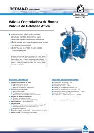
Classic <strong>Deluge</strong> <strong>Valve</strong>s<br />
These BERMAD <strong>Deluge</strong> <strong>Valve</strong>s include Manual EasyLock Reset for latching the<br />
valve open in response to an electric, hydraulic, pneumatic, or electro-pneumatic<br />
signal. The <strong>Deluge</strong> <strong>Valve</strong> resets to the closed position only upon local manual<br />
reset activation.<br />
Classic<br />
<strong>Deluge</strong>
Classic<br />
<strong>Deluge</strong>
BERMAD Fire Protection<br />
<strong>Model</strong>: FP 400E-2M<br />
System Components<br />
1 - Main <strong>Valve</strong>, BERMAD FP 400E Series<br />
2A - Gauge <strong>Valve</strong><br />
3A - Pressure Gauge<br />
4B - Priming Strainer<br />
5A - Drain <strong>Valve</strong><br />
11A - Alarm Shutoff <strong>Valve</strong><br />
14A - Check <strong>Valve</strong><br />
14B - Solenoid <strong>Valve</strong><br />
15B - Manual Emergency Release<br />
18B - Priming Ball <strong>Valve</strong><br />
19B - Drip Check<br />
M - EasyLock Manual Reset<br />
Optional<br />
P - Pressure Switch<br />
W - Water Motor Assembly<br />
S - <strong>Valve</strong> Position Limit Switch / Switches<br />
UL Listed<br />
P<br />
11A<br />
3A<br />
14A<br />
2A<br />
M<br />
15B<br />
The BERMAD <strong>Model</strong> FP 400E-2M is<br />
UL-Listed when installed<br />
with specific components and accessories.<br />
1<br />
19B<br />
3A<br />
5A<br />
2A<br />
14B<br />
4B<br />
18B<br />
400 Series<br />
Hydraulic<br />
Electric<br />
Atmosphere
BERMAD Fire Protection<br />
<strong>Model</strong>: FP 400E-2M<br />
Technical Data<br />
Dimensions<br />
Size<br />
Th Tb<br />
Dv<br />
TI<br />
Ts Tw<br />
400 Series<br />
1½”, 2” 2½” 3” 4” 6” 8” 10” 12”<br />
mm inch mm inch mm inch mm inch mm inch mm inch mm inch mm inch<br />
(1) L1 205 81 /16 205 81 /16 257 101 /8 320 125 /8 415 165 /16 500 1911 /16 605 2313 /16 725 289 /16<br />
(2) L4 205 81 /16 N/A N/A 250 913 /16 320 125 /8 415 165 /16 500 1911 /16 N/A N/A N/A N/A<br />
TI 142 55 /8 142 55 /8 119 411 /16 84 35 /16 57 21 /4 - - - - - -<br />
Tw 228 9 220 8 11 /16 243 9 9 /16 253 10 312 12 5 /16 326 12 13 /16 346 13 5 /8 391 15 3 /8<br />
Ts 228 9 220 8 11 /16 243 9 9 /16 253 10 318 12 1 /2 326 12 13 /16 326 12 13 /16 391 15 3 /8<br />
Th 226 8 7 /8 242 9½ 262 10 5 /16 261 10 5 /16 356 14 407 16 407 16 546 21 1 /2<br />
Tb 278 10 1 /16 289 11 3 /8 300 11 13 /16 337 13 1 /4 378 14 7 /8 405 15 15 /16 413 16 1 /4 473 18 5 /8<br />
Dv Ø ¾” 1½” 1½” 2” 2” 2” 2” 2”<br />
Notes:<br />
1. L 1 is for flanged ANSI #150 and ISO PN16.<br />
2. L 4 is for grooved end connections (Ductile Iron <strong>On</strong>ly).<br />
Connection Standard<br />
• Flanged: ANSI B16.42 (Ductile Iron),<br />
B16.5 (Steel & Stainless Steel),<br />
B16.24 (Bronze)<br />
• ISO PN16<br />
• Grooved: ANSI/AWWA C606 for 2, 3, 4, 6 & 8”<br />
Water Temperature<br />
• 0.5 – 50°C (33 – 122°F)<br />
Manufacturers Standard Materials<br />
Main valve body and cover<br />
• Ductile Iron ASTM A-536<br />
Main valve internals<br />
• Stainless Steel & Elastomer<br />
Control Trim System<br />
• Brass control components/accessories<br />
• Stainless Steel 316 tubing & fittings<br />
Elastomers<br />
• Nylon fabric reinforced polyisoprene NR<br />
Coating<br />
• Electrostatic Powder Coating<br />
Red (RAL 3002)<br />
Available Sizes<br />
• 1½, 2, 2½, 3, 4, 6, 8, 10 & 12"<br />
• UL-Listed for sizes 1½, 2, 2½, 3, 4, 6, 8 & 10”<br />
Pressure Rating*<br />
• Max. working pressure: 250 psi (17 bar)<br />
* Pressure rating might be limited due to solenoid valve rating<br />
Optional Materials<br />
Main valve body<br />
• Carbon Steel ASTM A-216 WCB<br />
• Stainless Steel 316<br />
• Ni-Al-Bronze ASTM B-148<br />
Control Trim<br />
• Stainless Steel 316<br />
• Monel® and Ni-Al-Bronze<br />
• Hastalloy C-276<br />
Elastomers<br />
• NBR<br />
• EPDM<br />
Coating<br />
• High Build Epoxy Fusion-Bonded<br />
with UV Protection, Anti-Corrosion<br />
bermadfire@bermad.com • www.bermad.com<br />
The information herein is subject to change without notice. BERMAD shall not be held<br />
liable for any errors. All rights reserved. © Copyright by BERMAD. PE4PE-2M 11<br />
3. Provide adequate space around valve for maintenance.<br />
4. Data is for envelope dimensions, specific component positioning may vary.<br />
L 1<br />
L 4<br />
Wet Pilot Line Elevation<br />
When used, refer to “Wet Pilot Line<br />
Maximum Elevation Above <strong>Valve</strong>” chart,<br />
<strong>Model</strong> FP 400E-1M<br />
Solenoid Pilot <strong>Valve</strong>s<br />
Standard<br />
• 2-Way Pilot Operated type<br />
• Brass body<br />
• Main valve closed when de-energized<br />
• Enclosure: General purpose watertight,<br />
NEMA 4 and 4X / IP65, Class F<br />
• Power: 24VDC, 8 watts<br />
• UL – Listed<br />
Options (see also ordering guide)<br />
• Hazardous locations:<br />
• Class l Division 1, Gr. A, B, C, D, T4 (code 7)<br />
• ATEX, EEx em llC T4 (code 8)<br />
• ATEX, EEx d llC T4/5 (code 9)<br />
• Voltage: see ordering guide (voltage options)<br />
• Stainless Steel 316 body material (code K)<br />
DOWNLOAD PDF VERSION
BERMAD Fire Protection<br />
<strong>Model</strong>: FP 400E-3M<br />
System Components<br />
1 - Main <strong>Valve</strong>, FP 400E Series<br />
2A - Gauge <strong>Valve</strong><br />
3A - Pressure Gauge<br />
4B - Priming Strainer<br />
5A - Drain <strong>Valve</strong><br />
6B - Pneumatic Pressure Operated Relief<br />
<strong>Valve</strong> (PORV)<br />
11A - Alarm Shutoff <strong>Valve</strong><br />
14A - Check <strong>Valve</strong><br />
14B - Solenoid <strong>Valve</strong><br />
15B - Manual Emergency Release<br />
18B - Priming <strong>Valve</strong><br />
19B - Drip Check<br />
M - EasyLock Manual Reset<br />
Optional<br />
P - Pressure Switch<br />
W - Water Motor Assembly<br />
S - <strong>Valve</strong> Position Limit Switch / Switches<br />
UL Listed<br />
P<br />
11A<br />
3A<br />
14A<br />
6B<br />
M<br />
14B<br />
15B<br />
4B<br />
The BERMAD <strong>Model</strong> FP 400E-3M is<br />
UL-Listed when installed<br />
with specific components and accessories.<br />
1<br />
19B<br />
3A<br />
5A<br />
2A<br />
18B<br />
400 Series<br />
Hydraulic<br />
Electric<br />
Pneumatic<br />
Atmosphere
BERMAD Fire Protection<br />
<strong>Model</strong>: FP 400E-3M<br />
Technical Data<br />
Dimensions<br />
Size<br />
Th Tb<br />
Dv<br />
TI<br />
Ts Tw<br />
400 Series<br />
1½”, 2” 2½” 3” 4” 6” 8” 10” 12”<br />
mm inch mm inch mm inch mm inch mm inch mm inch mm inch mm inch<br />
(1) L1 205 81 /16 205 81 /16 257 101 /8 320 125 /8 415 165 /16 500 1911 /16 605 2313 /16 725 289 /16<br />
(2) L4 205 81 /16 N/A N/A 250 913 /16 320 125 /8 415 165 /16 500 1911 /16 N/A N/A N/A N/A<br />
TI 142 55 /8 142 55 /8 119 411 /16 84 35 /16 57 21 /4 - - - - - -<br />
Tw 228 9 220 8 11 /16 243 9 9 /16 253 10 312 12 5 /16 326 12 13 /16 346 13 5 /8 391 15 3 /8<br />
Ts 228 9 220 8 11 /16 243 9 9 /16 253 10 318 12 1 /2 326 12 13 /16 326 12 13 /16 391 15 3 /8<br />
Th 226 8 7 /8 242 9½ 262 10 5 /16 261 10 5 /16 356 14 407 16 407 16 546 21 1 /2<br />
Tb 278 10 1 /16 289 11 3 /8 300 11 13 /16 337 13 1 /4 378 14 7 /8 405 15 15 /16 413 16 1 /4 473 18 5 /8<br />
Dv Ø ¾” 1½” 1½” 2” 2” 2” 2” 2”<br />
Notes:<br />
1. L 1 is for flanged ANSI #150 and ISO PN16.<br />
2. L 4 is for grooved end connections (Ductile Iron <strong>On</strong>ly).<br />
Connection Standard<br />
• Flanged: ANSI B16.42 (Ductile Iron),<br />
B16.5 (Steel & Stainless Steel),<br />
B16.24 (Bronze) or ISO PN16<br />
• Grooved: ANSI/AWWA C606 for 2, 3, 4, 6 & 8”<br />
Water Temperature<br />
• 0.5 – 50°C (33 – 122°F)<br />
Manufacturers Standard Materials<br />
Main valve body and cover<br />
• Ductile Iron ASTM A-536<br />
Main valve internals<br />
• Stainless Steel 304 & Cast Iron<br />
Control Trim System<br />
• Brass control components/accessories<br />
• Stainless Steel 316 tubing & fittings<br />
Elastomers<br />
• Nylon fabric reinforced polyisoprene NR<br />
Coating<br />
• Electrostatic Powder Coating Polyester,<br />
Red (RAL 3002)<br />
Available Sizes<br />
• 1½, 2, 2½, 3, 4, 6, 8, 10 & 12"<br />
• UL-Listed for sizes 1½, 2, 2½, 3, 4, 6, 8 & 10”<br />
Pressure Rating<br />
• Max. working pressure: 250 psi (17 bar)<br />
Optional Materials<br />
Main valve body<br />
• Carbon Steel ASTM A-216 WCB<br />
• Stainless Steel 316<br />
• Ni-Al-Bronze ASTM B-148<br />
Control Trim<br />
• Stainless Steel 316<br />
• Monel® and Ni-Al-Bronze<br />
• Hastalloy C-276<br />
Elastomers<br />
• NBR<br />
• EPDM<br />
Coating<br />
• High Built Epoxy Fusion-Bonded<br />
with UV Protection, Anti-Corrosion<br />
bermadfire@bermad.com • www.bermad.com<br />
The information herein is subject to change without notice. BERMAD shall not be held<br />
liable for any errors. All rights reserved. © Copyright by BERMAD. PE4PE-3M 04<br />
3. Provide adequate space around valve for maintenance.<br />
4. Data is for envelope dimensions, specific component positioning may vary.<br />
L 1<br />
L 4<br />
PORV Setting<br />
<strong>Valve</strong> opens on pilot line pressure drop<br />
factory set: 20 psi (1.5 bar)<br />
Solenoid Pilot <strong>Valve</strong>s<br />
Standard<br />
• 3-Way, direct actuated type<br />
• Brass body<br />
• Main valve closed when de-energized<br />
• Enclosure: General purpose watertight,<br />
NEMA 4 and 4X / IP65, Class F<br />
• Power: 24VDC, 8 watts<br />
• UL – Listed<br />
Options (see also ordering guide)<br />
• Hazardous locations:<br />
• Class l Division 1, Gr. A, B, C, D, T4 (code 7)<br />
• Class l Division 2, Gr. A, B, C, D, T4<br />
• ATEX, EEx d llC T5 (code 9)<br />
• Voltage: see ordering guide (voltage options)<br />
• Stainless Steel 316 body material (code K)<br />
DOWNLOAD PDF VERSION
BERMAD Fire Protection<br />
<strong>Model</strong>: FP 400E-4M<br />
System Components<br />
1 - Main <strong>Valve</strong>, FP 400E Series<br />
2A - Gauge <strong>Valve</strong><br />
3A - Pressure Gauge<br />
4B - Priming Strainer<br />
5A - Drain <strong>Valve</strong><br />
6B - Pneumatic Pressure Operated Relief<br />
<strong>Valve</strong> (PORV)<br />
11A - Alarm Shutoff <strong>Valve</strong><br />
14A - Check <strong>Valve</strong><br />
15B - Manual Emergency Release<br />
18B - Priming Ball <strong>Valve</strong><br />
19B - Drip Check<br />
M - EasyLock Manual Reset<br />
Optional<br />
P - Pressure Switch<br />
W - Water Motor Assembly<br />
S - <strong>Valve</strong> Position Limit Switch / Switches<br />
UL Listed<br />
P<br />
11A<br />
3A<br />
6B<br />
M<br />
15B<br />
The BERMAD <strong>Model</strong> FP 400E-4M is<br />
UL-Listed when installed<br />
with specific components and accessories.<br />
1<br />
19B<br />
3A<br />
5A<br />
2A<br />
4B<br />
18B<br />
400 Series<br />
Hydraulic<br />
Pneumatic<br />
Atmosphere
BERMAD Fire Protection<br />
<strong>Model</strong>: FP 400E-4M<br />
Technical Data<br />
Dimensions<br />
Size<br />
Th Tb<br />
Dv<br />
TI<br />
Ts Tw<br />
400 Series<br />
1½”, 2” 2½” 3” 4” 6” 8” 10” 12”<br />
mm inch mm inch mm inch mm inch mm inch mm inch mm inch mm inch<br />
(1) L1 205 81 /16 205 81 /16 257 101 /8 320 125 /8 415 165 /16 500 1911 /16 605 2313 /16 725 289 /16<br />
(2) L4 205 81 /16 N/A N/A 250 913 /16 320 125 /8 415 165 /16 500 1911 /16 N/A N/A N/A N/A<br />
TI 142 55 /8 142 55 /8 119 411 /16 84 35 /16 57 21 /4 - - - - - -<br />
Tw 228 9 220 8 11 /16 243 9 9 /16 253 10 312 12 5 /16 326 12 13 /16 346 13 5 /8 391 15 3 /8<br />
Ts 228 9 220 8 11 /16 243 9 9 /16 253 10 318 12 1 /2 326 12 13 /16 326 12 13 /16 391 15 3 /8<br />
Th 226 8 7 /8 242 9½ 262 10 5 /16 261 10 5 /16 356 14 407 16 407 16 546 21 1 /2<br />
Tb 278 10 1 /16 289 11 3 /8 300 11 13 /16 337 13 1 /4 378 14 7 /8 405 15 15 /16 413 16 1 /4 473 18 5 /8<br />
Dv Ø ¾” 1½” 1½” 2” 2” 2” 2” 2”<br />
Notes:<br />
1. L 1 is for flanged ANSI #150 and ISO PN16.<br />
2. L 4 is for grooved end connections (Ductile Iron <strong>On</strong>ly).<br />
Connection Standard<br />
• Flanged: ANSI B16.42 (Ductile Iron),<br />
B16.5 (Steel & Stainless Steel),<br />
B16.24 (Bronze) or ISO PN16<br />
• Grooved: ANSI/AWWA C606 for 2, 3, 4, 6 & 8”<br />
Water Temperature<br />
• 0.5 – 50°C (33 – 122°F)<br />
Manufacturers Standard Materials<br />
Main valve body and cover<br />
• Ductile Iron ASTM A-536<br />
Main valve internals<br />
• Stainless Steel 304 & Cast Iron<br />
Control Trim System<br />
• Brass control components/accessories<br />
• Stainless Steel 316 tubing & fittings<br />
Elastomers<br />
• Nylon fabric reinforced polyisoprene NR<br />
Coating<br />
• Electrostatic Powder Coating Polyester,<br />
Red (RAL 3002)<br />
Available Sizes<br />
• 1½, 2, 2½, 3, 4, 6, 8, 10 & 12"<br />
• UL-Listed for sizes 1½, 2, 2½, 3, 4, 6, 8 & 10”<br />
Pressure Rating<br />
• Max. working pressure: 250 psi (17 bar)<br />
Optional Materials<br />
Main valve body<br />
• Carbon Steel ASTM A-216 WCB<br />
• Stainless Steel 316<br />
• Ni-Al-Bronze ASTM B-148<br />
Control Trim<br />
• Stainless Steel 316<br />
• Monel® and Ni-Al-Bronze<br />
• Hastalloy C-276<br />
Elastomers<br />
• NBR<br />
• EPDM<br />
Coating<br />
• High Built Epoxy Fusion-Bonded<br />
with UV Protection, Anti-Corrosion<br />
bermadfire@bermad.com • www.bermad.com<br />
The information herein is subject to change without notice. BERMAD shall not be held<br />
liable for any errors. All rights reserved. © Copyright by BERMAD. PE4PE-4M 04<br />
3. Provide adequate space around valve for maintenance.<br />
4. Data is for envelope dimensions, specific component positioning may vary.<br />
L 1<br />
L 4<br />
PORV Setting<br />
<strong>Valve</strong> opens on pilot line pressure drop<br />
factory set: 20 psi (1.5 bar)<br />
DOWNLOAD PDF VERSION
BERMAD Fire Protection<br />
<strong>Model</strong>: FP 400E-1M<br />
System Components<br />
1 - Main <strong>Valve</strong>, FP 400E Series<br />
2A - Gauge <strong>Valve</strong><br />
3A - Pressure Gauge<br />
4B - Priming Strainer<br />
5A - Drain <strong>Valve</strong><br />
11A - Alarm Shutoff <strong>Valve</strong><br />
14A - Check <strong>Valve</strong><br />
15B - Manual Emergency Release<br />
18B - Priming Ball <strong>Valve</strong><br />
19B - Drip Check<br />
M - EasyLock Manual Reset<br />
Optional<br />
P - Pressure Switch<br />
W - Water Motor Assembly<br />
S - <strong>Valve</strong> Position Limit Switch / Switches<br />
UL Listed<br />
11A<br />
3A<br />
14A<br />
2A<br />
M<br />
15B<br />
18B<br />
The BERMAD <strong>Model</strong> FP 400E-1M is<br />
UL-Listed when installed<br />
with specific components and accessories.<br />
1<br />
19B<br />
3A<br />
5A<br />
2A<br />
4B<br />
400 Series<br />
Hydraulic<br />
Atmosphere
BERMAD Fire Protection<br />
<strong>Model</strong>: FP 400E-1M<br />
Technical Data<br />
Dimensions<br />
Size<br />
Th Tb<br />
Dv<br />
Ts Tw<br />
400 Series<br />
1½”, 2” 2½” 3” 4” 6” 8” 10” 12”<br />
mm inch mm inch mm inch mm inch mm inch mm inch mm inch mm inch<br />
(1) L1 205 81 /16 205 81 /16 257 101 /8 320 125 /8 415 165 /16 500 1911 /16 605 2313 /16 725 289 /16<br />
(2) L4 205 81 /16 N/A N/A 250 913 /16 320 125 /8 415 165 /16 500 1911 /16 N/A N/A N/A N/A<br />
TI 142 55 /8 142 55 /8 119 411 /16 84 35 /16 57 21 /4 - - - - - -<br />
Tw 228 9 220 8 11 /16 243 9 9 /16 253 10 312 12 5 /16 326 12 13 /16 346 13 5 /8 391 15 3 /8<br />
Ts 228 9 220 8 11 /16 243 9 9 /16 253 10 318 12 1 /2 326 12 13 /16 326 12 13 /16 391 15 3 /8<br />
Th 226 8 7 /8 242 9½ 262 10 5 /16 261 10 5 /16 356 14 407 16 407 16 546 21 1 /2<br />
Tb 278 10 1 /16 289 11 3 /8 300 11 13 /16 337 13 1 /4 378 14 7 /8 405 15 15 /16 413 16 1 /4 473 18 5 /8<br />
Dv Ø ¾” 1½” 1½” 2” 2” 2” 2” 2”<br />
Notes:<br />
1. L 1 is for flanged ANSI #150 and ISO PN16.<br />
2. L 4 is for grooved end connections (Ductile Iron <strong>On</strong>ly).<br />
3. Provide adequate space around valve for maintenance.<br />
4. Data is for envelope dimensions, specific component<br />
positioning may vary.<br />
Connection Standard<br />
• Flanged: ANSI B16.42 (Ductile Iron),<br />
B16.5 (Steel & Stainless Steel),<br />
B16.24 (Bronze) or ISO PN16<br />
• Grooved: ANSI/AWWA C606 for 2, 3, 4, 6 & 8"<br />
Water Temperature<br />
• 0.5 – 50°C (33 – 122°F)<br />
Available Sizes<br />
• 1½, 2, 2½, 3, 4, 6, 8, 10 & 12"<br />
• UL-Listed for sizes 1½, 2, 2½, 3, 4, 6, 8 & 10"<br />
Pressure Rating<br />
• Max. working pressure: 250 psi (17 bar)<br />
Manufacturers Standard Materials<br />
Main valve body and cover<br />
• Ductile Iron ASTM A-536<br />
Main valve internals<br />
• Stainless Steel 304 & Cast Iron<br />
Control Trim System<br />
• Brass control components/accessories<br />
• Stainless Steel 316 tubing & fittings<br />
Elastomers<br />
• Nylon fabric reinforced polyisoprene NR<br />
Coating<br />
• Electrostatic Powder Coating Polyester,<br />
Red (RAL 3002)<br />
Optional Materials<br />
Main valve body<br />
• Carbon Steel ASTM A-216 WCB<br />
• Stainless Steel 316<br />
• Ni-Al-Bronze ASTM B-148<br />
Control Trim<br />
• Stainless Steel 316<br />
• Monel® and Ni-Al-Bronze<br />
• Hastalloy C-276<br />
Elastomers<br />
• NBR<br />
• EPDM<br />
Coating<br />
• High Build Epoxy Fusion-Bonded<br />
with UV Protection, Anti-Corrosion<br />
bermadfire@bermad.com • www.bermad.com<br />
The information herein is subject to change without notice. BERMAD shall not be held<br />
liable for any errors. All rights reserved. © Copyright by BERMAD. PE4PE-1M 11<br />
Height ft (m)<br />
250 (75)<br />
200 (60)<br />
150 (45)<br />
100 (30)<br />
50 (15)<br />
0 (0)<br />
psi 20<br />
(bar) (1.3)<br />
40<br />
(2.7)<br />
TI<br />
L 1<br />
L 4<br />
Wet Pilot line Maximum Elevation Above <strong>Valve</strong><br />
<strong>Bermad</strong> 400E with EasyLock Manual Reset<br />
60<br />
(4.1)<br />
80<br />
(5.5)<br />
100<br />
(6.8)<br />
11/2-2”<br />
120<br />
(8.2)<br />
6”<br />
140<br />
(9.6)<br />
Inlet Pressure<br />
160<br />
(11)<br />
21/2”<br />
175<br />
(12)<br />
DOWNLOAD PDF VERSION<br />
200<br />
(13.8)<br />
3”<br />
8-12”<br />
225<br />
(15.5)<br />
4”<br />
250<br />
(17.2)
BERMAD Fire Protection<br />
<strong>Model</strong>: FP 400E-5M<br />
System Components<br />
1 - Main <strong>Valve</strong>, FP 400E Series<br />
2A - Pressure Gauge <strong>Valve</strong><br />
3A - Pressure Gauge<br />
4B - Priming Strainer<br />
5A - Drain <strong>Valve</strong><br />
6B - Adjustable, Pressure Operated Relief<br />
<strong>Valve</strong> (PORV-A)<br />
7B - Check <strong>Valve</strong><br />
11A - Alarm Shutoff <strong>Valve</strong><br />
14A - Check <strong>Valve</strong><br />
15B - Manual Emergency Release<br />
18B - Priming <strong>Valve</strong><br />
19B - Drip Check<br />
M - EasyLock Manual Reset<br />
Optional<br />
P - Pressure Switch<br />
W - Water Motor Assembly<br />
S - <strong>Valve</strong> Position Limit Switch / Switches<br />
UL Listed<br />
P<br />
11A<br />
3A<br />
14A<br />
6B<br />
M<br />
15B<br />
3B<br />
The BERMAD <strong>Model</strong> FP 400E-5M is<br />
UL-Listed when installed<br />
with specific components and accessories.<br />
1<br />
19B<br />
3A<br />
5A<br />
2A<br />
7B<br />
18B<br />
4B<br />
400 Series<br />
Hydraulic<br />
Atmosphere
BERMAD Fire Protection<br />
<strong>Model</strong>: FP 400E-5M<br />
Technical Data<br />
Dimensions<br />
Size<br />
Th Tb<br />
Dv<br />
TI<br />
Ts Tw<br />
400 Series<br />
1½”, 2” 2½” 3” 4” 6” 8” 10” 12”<br />
mm inch mm inch mm inch mm inch mm inch mm inch mm inch mm inch<br />
(1) L1 205 81 /16 205 81 /16 257 101 /8 320 125 /8 415 165 /16 500 1911 /16 605 2313 /16 725 289 /16<br />
(2) L4 205 81 /16 N/A N/A 250 913 /16 320 125 /8 415 165 /16 500 1911 /16 N/A N/A N/A N/A<br />
TI 142 55 /8 142 55 /8 119 411 /16 84 35 /16 57 21 /4 - - - - - -<br />
Tw 228 9 220 8 11 /16 243 9 9 /16 253 10 312 12 5 /16 326 12 13 /16 346 13 5 /8 391 15 3 /8<br />
Ts 228 9 220 8 11 /16 243 9 9 /16 253 10 318 12 1 /2 326 12 13 /16 326 12 13 /16 391 15 3 /8<br />
Th 226 8 7 /8 242 9½ 262 10 5 /16 261 10 5 /16 356 14 407 16 407 16 546 21 1 /2<br />
Tb 278 10 1 /16 289 11 3 /8 300 11 13 /16 337 13 1 /4 378 14 7 /8 405 15 15 /16 413 16 1 /4 473 18 5 /8<br />
Dv Ø ¾” 1½” 1½” 2” 2” 2” 2” 2”<br />
Notes:<br />
1. L 1 is for flanged ANSI #150 and ISO PN16.<br />
2. L 4 is for grooved end connections (Ductile Iron <strong>On</strong>ly).<br />
Connection Standard<br />
• Flanged: ANSI B16.42 (Ductile Iron),<br />
B16.5 (Steel & Stainless Steel),<br />
B16.24 (Bronze) or ISO PN16<br />
• Grooved: ANSI/AWWA C606 for 2, 3, 4, 6 & 8”<br />
Water Temperature<br />
• 0.5 – 50°C (33 – 122°F)<br />
Manufacturers Standard Materials<br />
Main valve body and cover<br />
• Ductile Iron ASTM A-536<br />
Main valve internals<br />
• Stainless Steel 304 & Cast Iron<br />
Control Trim System<br />
• Brass control components/accessories<br />
• Stainless Steel 316 tubing & fittings<br />
Elastomers<br />
• Nylon fabric reinforced polyisoprene NR<br />
Coating<br />
• Electrostatic Powder Coating Polyester,<br />
Red (RAL 3002)<br />
Available Sizes<br />
• 1½, 2, 2½, 3, 4, 6, 8, 10 & 12"<br />
• UL-Listed for sizes 1½, 2, 2½, 3, 4, 6, 8 & 10”<br />
Pressure Rating<br />
• Max. working pressure: 250 psi (17 bar)<br />
Optional Materials<br />
Main valve body<br />
• Carbon Steel ASTM A-216 WCB<br />
• Stainless Steel 316<br />
• Ni-Al-Bronze ASTM B-148<br />
Control Trim<br />
• Stainless Steel 316<br />
• Monel® and Ni-Al-Bronze<br />
• Hastalloy C-276<br />
Elastomers<br />
• NBR<br />
• EPDM<br />
Coating<br />
• High Built Epoxy Fusion-Bonded<br />
with UV Protection, Anti-Corrosion<br />
bermadfire@bermad.com • www.bermad.com<br />
The information herein is subject to change without notice. BERMAD shall not be held<br />
liable for any errors. All rights reserved. © Copyright by BERMAD. PE4PE-5M 04<br />
3. Provide adequate space around valve for maintenance.<br />
4. Data is for envelope dimensions, specific component positioning may vary.<br />
L 1<br />
L 4<br />
PORV Setting<br />
<strong>Valve</strong> opens on pilot line pressure drop<br />
• Factory Set: 72 psi (5 bar)<br />
• Adjustable Range: 10-115 psi (0.7-8 bar)<br />
Warning: The release point must be set at<br />
the maximum elevation of the highest wet<br />
pilot line release device above the main<br />
valve plus at least 10 psi (0.7 bar).<br />
DOWNLOAD PDF VERSION
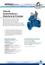
Combination Pressure<br />
Control <strong>Deluge</strong> <strong>Valve</strong>s<br />
The BERMAD Combination Pressure Control <strong>Deluge</strong> <strong>Valve</strong>s are suitable for flow<br />
control in large scale firewater systems. The valves can be activated in response<br />
to an electric, hydraulic, pneumatic, or electro-pneumatic signal. When open, the<br />
valves continuously reduce higher upstream pressure to a lower pre-set down-<br />
stream pressure, maintaining flow per system design.<br />
Pressure<br />
Control<br />
<strong>Deluge</strong>
Pressure<br />
Control<br />
<strong>Deluge</strong>
BERMAD Fire Protection<br />
<strong>Model</strong>: FP 400E-2MC<br />
System Components<br />
1 - Main <strong>Valve</strong>, BERMAD FP 400E Series<br />
2A - Gauge <strong>Valve</strong><br />
2B - Accelerator with Priming Restriction<br />
2R - Pressure Reducing Pilot<br />
3A - Pressure Gauge (3 units)<br />
4B - Priming Strainer<br />
5A - Drain <strong>Valve</strong><br />
7B - Check <strong>Valve</strong><br />
11A - Alarm Shutoff <strong>Valve</strong><br />
14A - Check <strong>Valve</strong><br />
14B - Solenoid <strong>Valve</strong><br />
15B - Manual Emergency Release<br />
18B - Priming Ball <strong>Valve</strong><br />
19B - Drip Check<br />
26B - Hydraulic Relay <strong>Valve</strong> (HRV)<br />
M - EasyLock Manual Reset<br />
Optional<br />
P - Pressure Switch<br />
W - Water Motor Assembly<br />
S - <strong>Valve</strong> Position<br />
Limit Switch / Switches<br />
UL Listed<br />
14A<br />
14B<br />
M<br />
7B<br />
4B<br />
26B<br />
2B<br />
18B<br />
P<br />
11A<br />
The BERMAD <strong>Model</strong> FP 400E-2MC is<br />
UL-Listed when installed<br />
with specific components and accessories.<br />
1<br />
19B<br />
3A<br />
5A<br />
2A<br />
2R<br />
15B<br />
400 Series<br />
Hydraulic<br />
Electric<br />
Atmosphere
BERMAD Fire Protection<br />
<strong>Model</strong>: FP 400E-2MC<br />
Technical Data<br />
Dimensions<br />
Size<br />
Th Tb<br />
Dv<br />
TI<br />
Ts Tw<br />
400 Series<br />
1½”, 2” 2½” 3” 4” 6” 8” 10” 12”<br />
mm inch mm inch mm inch mm inch mm inch mm inch mm inch mm inch<br />
(1) L1 205 81 /16 205 81 /16 257 101 /8 320 125 /8 415 165 /16 500 1911 /16 605 2313 /16 725 289 /16<br />
(2) L4 205 81 /16 N/A N/A 250 913 /16 320 125 /8 415 165 /16 500 1911 /16 N/A N/A N/A N/A<br />
TI 142 55 /8 142 55 /8 119 411 /16 84 35 /16 57 21 /4 - - - - - -<br />
Tw 228 9 220 8 11 /16 243 9 9 /16 253 10 312 12 5 /16 326 12 13 /16 346 13 5 /8 391 15 3 /8<br />
Ts 228 9 220 8 11 /16 243 9 9 /16 253 10 318 12 1 /2 326 12 13 /16 326 12 13 /16 391 15 3 /8<br />
Th 226 8 7 /8 242 9½ 262 10 5 /16 261 10 5 /16 356 14 407 16 407 16 546 21 1 /2<br />
Tb 278 10 1 /16 289 11 3 /8 300 11 13 /16 337 13 1 /4 378 14 7 /8 405 15 15 /16 413 16 1 /4 473 18 5 /8<br />
Dv Ø ¾” 1½” 1½” 2” 2” 2” 2” 2”<br />
Notes:<br />
1. L 1 is for flanged ANSI #150 and ISO PN16.<br />
2. L 4 is for grooved end connections (Ductile Iron <strong>On</strong>ly).<br />
3. Provide adequate space around valve for maintenance.<br />
4. Data is for envelope dimensions, specific component<br />
positioning may vary.<br />
Connection Standard<br />
• Flanged: ANSI B16.42 (Ductile Iron),<br />
B16.5 (Steel & Stainless Steel),<br />
B16.24 (Bronze) or ISO PN16<br />
• Grooved: ANSI/AWWA C606 for 2, 3, 4, 6 & 8”<br />
Water Temperature<br />
• 0.5 – 50°C (33 – 122°F)<br />
Available Sizes<br />
• 1½, 2, 2½, 3, 4, 6, 8, 10 & 12"<br />
• UL-Listed for sizes 1½, 2, 2½, 3, 4, 6, 8 & 10”<br />
Pressure Rating*<br />
• Max. inlet: 250 psi (17 bar)<br />
• Set: 30-165 psi (4.5-11.5 bar)<br />
* Pressure rating might be limited due to solenoid valve rating<br />
Manufacturers Standard Materials<br />
Main valve body and cover<br />
•Ductile Iron ASTM A-536<br />
Main valve internals<br />
•Stainless Steel 304 & Cast Iron<br />
Control Trim System<br />
•Brass control components/accessories<br />
•Forged Brass pressure reducing pilot<br />
with St. St. 304 internals & NBR<br />
elastomers<br />
•Stainless Steel 316 tubing & fittings<br />
Elastomers<br />
•Nylon fabric reinforced polyisoprene NR<br />
Coating<br />
•Electrostatic Powder Coating Polyester,<br />
Red (RAL 3002)<br />
Set<br />
Va lue<br />
Optional Materials<br />
Main valve body<br />
• Carbon Steel ASTM A-216 WCB<br />
• Stainless Steel 316<br />
• Ni-Al-Bronze ASTM B-148<br />
Control Trim<br />
• Stainless Steel 316<br />
• Monel® and Ni-Al-Bronze<br />
• Hastalloy C-276<br />
Elastomers<br />
• NBR<br />
• EPDM<br />
Coating<br />
• High Build Epoxy Fusion-Bonded<br />
with UV Protection, Anti-Corrosion<br />
bermadfire@bermad.com • www.bermad.com<br />
The information herein is subject to change without notice. BERMAD shall not be held<br />
liable for any errors. All rights reserved. © Copyright by BERMAD. PE4PE-2MC 11<br />
psi<br />
-2.0<br />
-4.0<br />
-6.0<br />
-8.0<br />
-10.0<br />
-12.0<br />
-14.0<br />
-16.0<br />
-18.0<br />
-20.0<br />
m 3 /h<br />
<strong>Valve</strong> Outlet Pressure Fall-off Characteristics<br />
<strong>On</strong> Inlet Under Set Pressure<br />
21 1 /2”<br />
1 /2, 2” 3” 4” 6” 8” 10”<br />
gpm<br />
20<br />
30<br />
90<br />
120<br />
50<br />
200<br />
70<br />
300<br />
600<br />
150<br />
200<br />
800<br />
1200<br />
300<br />
2000<br />
500<br />
700<br />
3000<br />
800<br />
900<br />
1200<br />
4000<br />
5000<br />
-0.0<br />
-0.3<br />
-0.4<br />
-0.7<br />
-1.0<br />
-1.2<br />
-1.4<br />
L 1<br />
L 4<br />
Solenoid Pilot <strong>Valve</strong>s<br />
Standard<br />
• 2-way Pilot Operated type<br />
• Brass body<br />
• Main valve closed when de-energized<br />
• Enclosure: General purpose watertight,<br />
NEMA 4 and 4X / IP65, Class F<br />
• Power: 24VDC, 8 watts<br />
• UL - Listed<br />
Options (see also ordering guide)<br />
• Hazardous locations:<br />
• Class l Division 1, Gr. A, B, C, D, T4 (code 7)<br />
• ATEX, EEx em llC T4 (code 8)<br />
• ATEX, EEx d llC T4/5 (code 9)<br />
• Voltage: see ordering guide (voltage option table)<br />
• Stainless steel 316 body material (code K)<br />
DOWNLOAD PDF VERSION<br />
12”<br />
bar
BERMAD Fire Protection<br />
<strong>Model</strong>: FP 400E-3DC<br />
System Components<br />
1 - Main <strong>Valve</strong>, BERMAD FP 400E Series<br />
2B - Accelerator with Priming Restriction<br />
2R - Pressure Reducing Pilot<br />
4B - Priming Strainer<br />
7B - Check <strong>Valve</strong><br />
15B - Manual Emergency Release<br />
18B - Priming Ball <strong>Valve</strong><br />
19B - Drip Check<br />
24B - 3-Way Solenoid<br />
26B - Hydraulic Relay <strong>Valve</strong> (HRV)<br />
Optional<br />
S - <strong>Valve</strong> Position Limit Switch / Switches<br />
UL Listed<br />
7B<br />
2B<br />
4B<br />
18B<br />
The BERMAD <strong>Model</strong> FP 400E-3DC is UL-Listed.<br />
The installation shall include Indicating and Drain Components.<br />
1<br />
24B<br />
26B<br />
2R<br />
15B<br />
400 Series<br />
Hydraulic<br />
Electric<br />
Atmosphere
BERMAD Fire Protection<br />
<strong>Model</strong>: FP 400E-3DC<br />
Technical Data<br />
Dimensions<br />
Size<br />
Th<br />
Tb<br />
L 1<br />
L 4<br />
Ts Tw<br />
400 Series<br />
1½”, 2” 2½” 3” 4” 6” 8” 10” 12”<br />
mm inch mm inch mm inch mm inch mm inch mm inch mm inch mm inch<br />
(1) L1 205 81 /16 205 81 /16 257 101 /8 320 125 /8 415 165 /16 500 1911 /16 605 2313 /16 725 289 /16<br />
(2) L4 205 81 /16 N/A N/A 250 913 /16 320 125 /8 415 165 /16 500 1911 /16 N/A N/A N/A N/A<br />
Tw 228 9 220 8 11 /16 243 9 9 /16 253 10 312 12 5 /16 326 12 13 /16 346 13 5 /8 391 15 3 /8<br />
Ts 228 9 220 8 11 /16 243 9 9 /16 253 10 318 12 1 /2 326 12 13 /16 326 12 13 /16 391 15 3 /8<br />
Th 226 8 7 /8 242 9½ 262 10 5 /16 261 10 5 /16 356 14 407 16 407 16 546 21 1 /2<br />
Tb 278 10 1 /16 289 11 3 /8 300 11 13 /16 337 13 1 /4 378 14 7 /8 405 15 15 /16 413 16 1 /4 473 18 5 /8<br />
Notes:<br />
1. L 1 is for flanged ANSI #150 and ISO PN16.<br />
2. L 4 is for grooved end connections (Ductile Iron <strong>On</strong>ly).<br />
3. Provide adequate space around valve for maintenance.<br />
4. Data is for envelope dimensions, specific component<br />
positioning may vary.<br />
Connection Standard<br />
• Flanged: ANSI B16.42 (Ductile Iron),<br />
B16.5 (Steel & Stainless Steel),<br />
B16.24 (Bronze) or ISO PN16<br />
• Grooved: ANSI/AWWA C606 for 2, 3, 4, 6 & 8”<br />
Water Temperature<br />
• 0.5 – 50°C (33 – 122°F)<br />
Available Sizes<br />
• 1½, 2, 2½, 3, 4, 6, 8, 10 & 12"<br />
• UL-Listed for sizes 1½, 2, 2½, 3, 4, 6, 8 & 10”<br />
Pressure Rating*<br />
• Max. inlet: 250 psi (17 bar)<br />
• Set: 30-165 psi (4.5-11.5 bar)<br />
* Pressure rating might be limited due to solenoid valve rating<br />
Manufacturers Standard Materials<br />
Main valve body and cover<br />
•Ductile Iron ASTM A-536<br />
Main valve internals<br />
•Stainless Steel 304 & Cast Iron<br />
Control Trim System<br />
•Brass control components/accessories<br />
•Forged Brass pressure reducing pilot<br />
with St. St. 304 internals & NBR<br />
elastomers<br />
•Stainless Steel 316 tubing & fittings<br />
Elastomers<br />
•Nylon fabric reinforced polyisoprene NR<br />
Coating<br />
•Electrostatic Powder Coating Polyester,<br />
Red (RAL 3002)<br />
Set<br />
Va lue<br />
Optional Materials<br />
Main valve body<br />
• Carbon Steel ASTM A-216 WCB<br />
• Stainless Steel 316<br />
• Ni-Al-Bronze ASTM B-148<br />
Control Trim<br />
• Stainless Steel 316<br />
• Monel® and Ni-Al-Bronze<br />
• Hastalloy C-276<br />
Elastomers<br />
• NBR<br />
• EPDM<br />
Coating<br />
• High Build Epoxy Fusion-Bonded<br />
with UV Protection, Anti-Corrosion<br />
bermadfire@bermad.com • www.bermad.com<br />
The information herein is subject to change without notice. BERMAD shall not be held<br />
liable for any errors. All rights reserved. © Copyright by BERMAD. PE4PE-3DC 11<br />
psi<br />
-2.0<br />
-4.0<br />
-6.0<br />
-8.0<br />
-10.0<br />
-12.0<br />
-14.0<br />
-16.0<br />
-18.0<br />
-20.0<br />
m 3 /h<br />
<strong>Valve</strong> Outlet Pressure Fall-off Characteristics<br />
<strong>On</strong> Inlet Under Set Pressure<br />
21 1 /2”<br />
1 /2, 2” 3” 4” 6” 8” 10”<br />
gpm<br />
20<br />
30<br />
90<br />
120<br />
50<br />
200<br />
70<br />
300<br />
600<br />
150<br />
200<br />
800<br />
1200<br />
300<br />
2000<br />
500<br />
700<br />
3000<br />
800<br />
900<br />
1200<br />
4000<br />
5000<br />
-0.0<br />
-0.3<br />
-0.4<br />
-0.7<br />
-1.0<br />
-1.2<br />
-1.4<br />
Solenoid Pilot <strong>Valve</strong>s<br />
Standard<br />
• 3-Way direct actuated type<br />
• Brass body<br />
• Main valve closed when de-energized<br />
• Enclosure: General purpose watertight,<br />
NEMA 4 and 4X / IP65, Class F<br />
• Power: 24VDC, 8 watts<br />
• UL - Listed<br />
Options (see also ordering guide)<br />
• Hazardous locations:<br />
• Class l Division 1, Gr. A, B, C, D, T4 (code 7)<br />
• Class l Division 2, Gr. A, B, C, D, T4<br />
• ATEX, EEx d llC T5 (code 9)<br />
• Voltage: see ordering guide (voltage option table)<br />
• Stainless steel 316 body material (code K)<br />
DOWNLOAD PDF VERSION<br />
12”<br />
bar
BERMAD Fire Protection<br />
<strong>Model</strong>: FP 400E-6DC<br />
System Components<br />
1 - Main <strong>Valve</strong>, BERMAD FP 400E Series<br />
2B - Accelerator with Priming Restriction<br />
2R - Pressure Reducing Pilot<br />
4B - Priming Strainer<br />
6B - Pneumatic Pressure Operated Relief<br />
<strong>Valve</strong> (PORV)<br />
7B - Check <strong>Valve</strong><br />
15B - Manual Emergency Release<br />
18B - Priming Ball <strong>Valve</strong><br />
24B - 3-Way Solenoid<br />
Optional<br />
AMD - Air Maintenance Device<br />
S - <strong>Valve</strong> Position Limit Switch / Switches<br />
UL Listed<br />
24B<br />
2B<br />
7B<br />
4B<br />
18B<br />
The BERMAD <strong>Model</strong> FP 400E-6DC is UL-Listed.<br />
The installation shall include Indicating and Drain Components.<br />
1<br />
2R<br />
6B<br />
15B<br />
400 Series<br />
Hydraulic<br />
Electric<br />
Pneumatic<br />
Atmosphere
BERMAD Fire Protection<br />
<strong>Model</strong>: FP 400E-6DC<br />
Technical Data<br />
Dimensions<br />
Size<br />
Th<br />
Tb<br />
L 1<br />
L 4<br />
Ts Tw<br />
400 Series<br />
1½”, 2” 2½” 3” 4” 6” 8” 10” 12”<br />
mm inch mm inch mm inch mm inch mm inch mm inch mm inch mm inch<br />
(1) L1 205 81 /16 205 81 /16 257 101 /8 320 125 /8 415 165 /16 500 1911 /16 605 2313 /16 725 289 /16<br />
(2) L4 205 81 /16 N/A N/A 250 913 /16 320 125 /8 415 165 /16 500 1911 /16 N/A N/A N/A N/A<br />
Tw 228 9 220 8 11 /16 243 9 9 /16 253 10 312 12 5 /16 326 12 13 /16 346 13 5 /8 391 15 3 /8<br />
Ts 228 9 220 8 11 /16 243 9 9 /16 253 10 318 12 1 /2 326 12 13 /16 326 12 13 /16 391 15 3 /8<br />
Th 226 8 7 /8 242 9½ 262 10 5 /16 261 10 5 /16 356 14 407 16 407 16 546 21 1 /2<br />
Tb 278 10 1 /16 289 11 3 /8 300 11 13 /16 337 13 1 /4 378 14 7 /8 405 15 15 /16 413 16 1 /4 473 18 5 /8<br />
Notes:<br />
1. L 1 is for flanged ANSI #150 and ISO PN16.<br />
2. L 4 is for grooved end connections (Ductile Iron <strong>On</strong>ly).<br />
3. Provide adequate space around valve for maintenance.<br />
4. Data is for envelope dimensions, specific component<br />
positioning may vary.<br />
Connection Standard<br />
• Flanged: ANSI B16.42 (Ductile Iron),<br />
B16.5 (Steel & Stainless Steel),<br />
B16.24 (Bronze) or ISO PN16<br />
• Grooved: ANSI/AWWA C606 for 2, 3, 4, 6 & 8”<br />
Water Temperature<br />
• 0.5 – 50°C (33 – 122°F)<br />
Available Sizes<br />
• 1½, 2, 2½, 3, 4, 6, 8, 10 & 12"<br />
• UL-Listed for sizes 1½, 2, 2½, 3, 4, 6, 8 & 10”<br />
Pressure Rating<br />
• Max. inlet: 250 psi (17 bar)<br />
• Set: 30-165 psi (4.5-11.5 bar)<br />
Manufacturers Standard Materials<br />
Main valve body and cover<br />
•Ductile Iron ASTM A-536<br />
Main valve internals<br />
•Stainless Steel 304 & Cast Iron<br />
Control Trim System<br />
•Brass control components/accessories<br />
•Forged Brass pressure reducing pilot<br />
with St. St. 304 internals & NBR<br />
elastomers<br />
•Stainless Steel 316 tubing & fittings<br />
Elastomers<br />
•Nylon fabric reinforced polyisoprene NR<br />
Coating<br />
•Electrostatic Powder Coating Polyester,<br />
Red (RAL 3002)<br />
Set<br />
Va lue<br />
Optional Materials<br />
Main valve body<br />
• Carbon Steel ASTM A-216 WCB<br />
• Stainless Steel 316<br />
• Ni-Al-Bronze ASTM B-148<br />
Control Trim<br />
• Stainless Steel 316<br />
• Monel® and Ni-Al-Bronze<br />
• Hastalloy C-276<br />
Elastomers<br />
• NBR<br />
• EPDM<br />
Coating<br />
• High Build Epoxy Fusion-Bonded<br />
with UV Protection, Anti-Corrosion<br />
PORV set - opens on pressure drop<br />
• Factory set: 20 psi (1.5 bar)<br />
PORV setting<br />
<strong>Valve</strong> opens on pilot line pressure drop<br />
• Factory set: 20 psi (1.5 bar)<br />
bermadfire@bermad.com • www.bermad.com<br />
The information herein is subject to change without notice. BERMAD shall not be held<br />
liable for any errors. All rights reserved. © Copyright by BERMAD. PE4PE-6DC 11<br />
psi<br />
-2.0<br />
-4.0<br />
-6.0<br />
-8.0<br />
-10.0<br />
-12.0<br />
-14.0<br />
-16.0<br />
-18.0<br />
-20.0<br />
m 3 /h<br />
<strong>Valve</strong> Outlet Pressure Fall-off Characteristics<br />
<strong>On</strong> Inlet Under Set Pressure<br />
21 1 /2”<br />
1 /2, 2” 3” 4” 6” 8” 10”<br />
gpm<br />
20<br />
30<br />
90<br />
120<br />
50<br />
200<br />
70<br />
300<br />
600<br />
150<br />
200<br />
800<br />
1200<br />
300<br />
2000<br />
500<br />
700<br />
3000<br />
800<br />
900<br />
1200<br />
4000<br />
5000<br />
-0.0<br />
-0.3<br />
-0.4<br />
-0.7<br />
-1.0<br />
-1.2<br />
-1.4<br />
Solenoid Pilot <strong>Valve</strong>s<br />
Standard<br />
• 3-Way direct actuated type<br />
• Brass body<br />
• Main valve closed when de-energized<br />
• Enclosure: General purpose watertight,<br />
NEMA 4 and 4X / IP65, Class F<br />
• Power: 24VDC, 8 watts<br />
• UL - Listed<br />
Options (see also ordering guide)<br />
• Hazardous locations:<br />
• Class l Division 1, Gr. A, B, C, D, T4 (code 7)<br />
• Class l Division 2, Gr. A, B, C, D, T4<br />
• ATEX, EEx d llC T5 (code 9)<br />
• Voltage: see ordering guide (voltage option table)<br />
• Stainless steel 316 body material (code K)<br />
DOWNLOAD PDF VERSION<br />
12”<br />
bar
BERMAD Fire Protection<br />
<strong>Model</strong>: FP 400E-4DC<br />
System Components<br />
1 - Main <strong>Valve</strong>, BERMAD FP 400E Series<br />
2B - Accelerator with Priming Restriction<br />
2R - Pressure Reducing Pilot<br />
4B - Priming Strainer<br />
6B - Pneumatic Pressure Operated Relief<br />
<strong>Valve</strong> (PORV)<br />
7B - Check <strong>Valve</strong><br />
15B - Manual Emergency Release<br />
18B - Priming Ball <strong>Valve</strong><br />
Optional<br />
AMD - Air Maintenance Device<br />
S - <strong>Valve</strong> Position Limit Switch / Switches<br />
UL Listed<br />
2B<br />
7B<br />
4B<br />
18B<br />
The BERMAD <strong>Model</strong> FP 400E-4DC is UL-Listed.<br />
The installation shall include Indicating and Drain Components.<br />
1<br />
2R<br />
6B<br />
15B<br />
400 Series<br />
Regulated & Restricted<br />
Pneumatic Pressure Supply from<br />
AMD, Air Maintenance Device<br />
Hydraulic<br />
Pneumatic<br />
Atmosphere
BERMAD Fire Protection<br />
<strong>Model</strong>: FP 400E-4DC<br />
Technical Data<br />
Dimensions<br />
Size<br />
Th<br />
Tb<br />
L 1<br />
L 4<br />
Ts Tw<br />
400 Series<br />
1½”, 2” 2½” 3” 4” 6” 8” 10” 12”<br />
mm inch mm inch mm inch mm inch mm inch mm inch mm inch mm inch<br />
(1) L1 205 81 /16 205 81 /16 257 101 /8 320 125 /8 415 165 /16 500 1911 /16 605 2313 /16 725 289 /16<br />
(2) L4 205 81 /16 N/A N/A 250 913 /16 320 125 /8 415 165 /16 500 1911 /16 N/A N/A N/A N/A<br />
Tw 228 9 220 8 11 /16 243 9 9 /16 253 10 312 12 5 /16 326 12 13 /16 346 13 5 /8 391 15 3 /8<br />
Ts 228 9 220 8 11 /16 243 9 9 /16 253 10 318 12 1 /2 326 12 13 /16 326 12 13 /16 391 15 3 /8<br />
Th 226 8 7 /8 242 9½ 262 10 5 /16 261 10 5 /16 356 14 407 16 407 16 546 21 1 /2<br />
Tb 278 10 1 /16 289 11 3 /8 300 11 13 /16 337 13 1 /4 378 14 7 /8 405 15 15 /16 413 16 1 /4 473 18 5 /8<br />
Notes:<br />
1. L 1 is for flanged ANSI #150 and ISO PN16.<br />
2. L 4 is for grooved end connections (Ductile Iron <strong>On</strong>ly).<br />
3. Provide adequate space around valve for maintenance.<br />
4. Data is for envelope dimensions, specific component<br />
positioning may vary.<br />
Connection Standard<br />
• Flanged: ANSI B16.42 (Ductile Iron),<br />
B16.5 (Steel & Stainless Steel),<br />
B16.24 (Bronze) or ISO PN16<br />
• Grooved: ANSI/AWWA C606 for 2, 3, 4, 6 & 8”<br />
Water Temperature<br />
• 0.5 – 50°C (33 – 122°F)<br />
Available Sizes<br />
• 1½, 2, 2½, 3, 4, 6, 8, 10 & 12"<br />
• UL-Listed for sizes 1½, 2, 2½, 3, 4, 6, 8 & 10”<br />
Pressure Rating<br />
• Max. inlet: 250 psi (17 bar)<br />
• Set: 30-165 psi (4.5-11.5 bar)<br />
Manufacturers Standard Materials<br />
Main valve body and cover<br />
•Ductile Iron ASTM A-536<br />
Main valve internals<br />
•Stainless Steel 304 & Cast Iron<br />
Control Trim System<br />
•Brass control components/accessories<br />
•Forged Brass pressure reducing pilot<br />
with St. St. 304 internals & NBR<br />
elastomers<br />
•Stainless Steel 316 tubing & fittings<br />
Elastomers<br />
•Nylon fabric reinforced polyisoprene NR<br />
Coating<br />
•Electrostatic Powder Coating Polyester,<br />
Red (RAL 3002)<br />
Set<br />
Va lue<br />
Optional Materials<br />
Main valve body<br />
• Carbon Steel ASTM A-216 WCB<br />
• Stainless Steel 316<br />
• Ni-Al-Bronze ASTM B-148<br />
Control Trim<br />
• Stainless Steel 316<br />
• Monel® and Ni-Al-Bronze<br />
• Hastalloy C-276<br />
Elastomers<br />
• NBR<br />
• EPDM<br />
Coating<br />
• High Build Epoxy Fusion-Bonded<br />
with UV Protection, Anti-Corrosion<br />
PORV setting<br />
<strong>Valve</strong> opens on pilot line pressure drop<br />
• Factory set: 20 psi (1.5 bar)<br />
bermadfire@bermad.com • www.bermad.com<br />
The information herein is subject to change without notice. BERMAD shall not be held<br />
liable for any errors. All rights reserved. © Copyright by BERMAD. PE4PE-4DC 11<br />
psi<br />
-2.0<br />
-4.0<br />
-6.0<br />
-8.0<br />
-10.0<br />
-12.0<br />
-14.0<br />
-16.0<br />
-18.0<br />
-20.0<br />
m 3 /h<br />
<strong>Valve</strong> Outlet Pressure Fall-off Characteristics<br />
<strong>On</strong> Inlet Under Set Pressure<br />
21 1 /2”<br />
1 /2, 2” 3” 4” 6” 8” 10”<br />
gpm<br />
20<br />
30<br />
90<br />
120<br />
50<br />
200<br />
70<br />
300<br />
600<br />
150<br />
200<br />
800<br />
1200<br />
300<br />
2000<br />
500<br />
700<br />
3000<br />
DOWNLOAD PDF VERSION<br />
800<br />
900<br />
1200<br />
4000<br />
12”<br />
5000<br />
-0.0<br />
-0.3<br />
-0.4<br />
-0.7<br />
-1.0<br />
-1.2<br />
-1.4<br />
bar
BERMAD Fire Protection<br />
<strong>Model</strong>: FP 400E-5DC<br />
System Components<br />
1 - Main <strong>Valve</strong>, BERMAD FP 400E Series<br />
2B - Accelerator with Priming Restriction<br />
2R - Pressure Reducing Pilot<br />
4B - Priming Strainer<br />
7B - Check <strong>Valve</strong><br />
15B - Manual Emergency Release<br />
18B - Priming Ball <strong>Valve</strong><br />
26B - Hydraulic Relay <strong>Valve</strong> (HRV)<br />
Optional<br />
S - <strong>Valve</strong> Position Limit Switch / Switches<br />
UL Listed<br />
2B<br />
7B<br />
4B<br />
18B<br />
The BERMAD <strong>Model</strong> FP 400E-5DC is UL-Listed.<br />
The installation shall include Indicating and Drain Components.<br />
1<br />
26B<br />
2R<br />
15B<br />
Hydraulic Pressure<br />
400 Series<br />
Hydraulic<br />
Atmosphere
BERMAD Fire Protection<br />
<strong>Model</strong>: FP 400E-5DC<br />
Technical Data<br />
Dimensions<br />
Size<br />
Th<br />
Tb<br />
L 1<br />
L 4<br />
Ts Tw<br />
400 Series<br />
1½”, 2” 2½” 3” 4” 6” 8” 10” 12”<br />
mm inch mm inch mm inch mm inch mm inch mm inch mm inch mm inch<br />
(1) L1 205 81 /16 205 81 /16 257 101 /8 320 125 /8 415 165 /16 500 1911 /16 605 2313 /16 725 289 /16<br />
(2) L4 205 81 /16 N/A N/A 250 913 /16 320 125 /8 415 165 /16 500 1911 /16 N/A N/A N/A N/A<br />
Tw 228 9 220 8 11 /16 243 9 9 /16 253 10 312 12 5 /16 326 12 13 /16 346 13 5 /8 391 15 3 /8<br />
Ts 228 9 220 8 11 /16 243 9 9 /16 253 10 318 12 1 /2 326 12 13 /16 326 12 13 /16 391 15 3 /8<br />
Th 226 8 7 /8 242 9½ 262 10 5 /16 261 10 5 /16 356 14 407 16 407 16 546 21 1 /2<br />
Tb 278 10 1 /16 289 11 3 /8 300 11 13 /16 337 13 1 /4 378 14 7 /8 405 15 15 /16 413 16 1 /4 473 18 5 /8<br />
Notes:<br />
1. L 1 is for flanged ANSI #150 and ISO PN16.<br />
2. L 4 is for grooved end connections (Ductile Iron <strong>On</strong>ly).<br />
3. Provide adequate space around valve for maintenance.<br />
4. Data is for envelope dimensions, specific component<br />
positioning may vary.<br />
Connection Standard<br />
• Flanged: ANSI B16.42 (Ductile Iron),<br />
B16.5 (Steel & Stainless Steel),<br />
B16.24 (Bronze) or ISO PN16<br />
• Grooved: ANSI/AWWA C606 for 2, 3, 4, 6 & 8”<br />
Water Temperature<br />
• 0.5 – 50°C (33 – 122°F)<br />
Available Sizes<br />
• 1½, 2, 2½, 3, 4, 6, 8, 10 & 12"<br />
• UL-Listed for sizes 1½, 2, 2½, 3, 4, 6, 8 & 10”<br />
Pressure Rating<br />
• Max. inlet: 250 psi (17 bar)<br />
• Set: 30-165 psi (4.5-11.5 bar)<br />
Manufacturers Standard Materials<br />
Main valve body and cover<br />
•Ductile Iron ASTM A-536<br />
Main valve internals<br />
•Stainless Steel 304 & Cast Iron<br />
Control Trim System<br />
•Brass control components/accessories<br />
•Forged Brass pressure reducing pilot<br />
with St. St. 304 internals & NBR<br />
elastomers<br />
•Stainless Steel 316 tubing & fittings<br />
Elastomers<br />
•Nylon fabric reinforced polyisoprene NR<br />
Coating<br />
•Electrostatic Powder Coating Polyester,<br />
Red (RAL 3002)<br />
Set<br />
Va lue<br />
Optional Materials<br />
Main valve body<br />
• Carbon Steel ASTM A-216 WCB<br />
• Stainless Steel 316<br />
• Ni-Al-Bronze ASTM B-148<br />
Control Trim<br />
• Stainless Steel 316<br />
• Monel® and Ni-Al-Bronze<br />
• Hastalloy C-276<br />
Elastomers<br />
• NBR<br />
• EPDM<br />
Coating<br />
• High Build Epoxy Fusion-Bonded<br />
with UV Protection, Anti-Corrosion<br />
bermadfire@bermad.com • www.bermad.com<br />
The information herein is subject to change without notice. BERMAD shall not be held<br />
liable for any errors. All rights reserved. © Copyright by BERMAD. PE4PE-5DC 11<br />
psi<br />
-2.0<br />
-4.0<br />
-6.0<br />
-8.0<br />
-10.0<br />
-12.0<br />
-14.0<br />
-16.0<br />
-18.0<br />
-20.0<br />
m 3 /h<br />
<strong>Valve</strong> Outlet Pressure Fall-off Characteristics<br />
<strong>On</strong> Inlet Under Set Pressure<br />
21 1 /2”<br />
1 /2, 2” 3” 4” 6” 8” 10”<br />
gpm<br />
20<br />
30<br />
90<br />
120<br />
50<br />
200<br />
70<br />
300<br />
600<br />
150<br />
200<br />
800<br />
1200<br />
300<br />
2000<br />
500<br />
700<br />
3000<br />
DOWNLOAD PDF VERSION<br />
800<br />
900<br />
1200<br />
4000<br />
12”<br />
5000<br />
-0.0<br />
-0.3<br />
-0.4<br />
-0.7<br />
-1.0<br />
-1.2<br />
-1.4<br />
bar
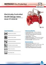
<strong>On</strong>-<strong>Off</strong> <strong>Deluge</strong> <strong>Valve</strong>s<br />
The BERMAD <strong>On</strong>-<strong>Off</strong> <strong>Deluge</strong> <strong>Valve</strong>s are intended for use in industrial remote<br />
resetting systems. The <strong>Deluge</strong> <strong>Valve</strong> can be electrically, hydraulically, pneumatically<br />
or electro-pneumatically remotely controlled to open and to reset closed.<br />
<strong>On</strong>-<strong>Off</strong><br />
<strong>Deluge</strong>
<strong>On</strong>-<strong>Off</strong><br />
<strong>Deluge</strong>
BERMAD Fire Protection<br />
<strong>Model</strong>: FP 400E-3D<br />
System Components<br />
1 - Main <strong>Valve</strong>, BERMAD FP 400E Series<br />
2B - Accelerator with Priming Restriction<br />
4B - Priming Strainer<br />
7B - Check <strong>Valve</strong><br />
15B - Manual Emergency Release<br />
24B - 3-Way Solenoid<br />
26B - Hydraulic Relay <strong>Valve</strong> (HRV-2)<br />
Optional<br />
P - Pressure Switch<br />
S - <strong>Valve</strong> Position Limit Switch / Switches<br />
UL Listed<br />
24B<br />
26B<br />
The BERMAD <strong>Model</strong> FP 400E-3D is UL-Listed.<br />
15B 7B<br />
The installation shall include Indicating and Drain Components.<br />
2B<br />
4B<br />
1<br />
Hydraulic<br />
Electric<br />
400 Series<br />
Atmosphere
BERMAD Fire Protection<br />
<strong>Model</strong>: FP 400E-3D<br />
Technical Data<br />
Dimensions<br />
Size<br />
Th<br />
Tb<br />
L 1 , L 4<br />
Dv<br />
Tw<br />
400 Series<br />
1½” 2” 2½” 3” 4” 6” 8” 10” 12”<br />
mm inch mm inch mm inch mm inch mm inch mm inch mm inch mm inch mm inch<br />
(1) L1 205 81 /16 205 81 /16 205 81 /16 257 102 /16 320 1210 /16 415 165 /16 500 1911 /16 607 2314 /16 725 289 /16<br />
(2) L4 205 81 /16 205 81 /16 N/A N/A 257 102 /16 320 1210 /16 N/A N/A 500 1911 /16 N/A N/A N/A N/A<br />
Tw 255 10 1 /16 255 10 1 /16 255 10 1 /16 255 10 1 /16 255 10 1 /16 255 10 1 /16 255 10 1 /16 255 10 1 /16 255 10 1 /16<br />
Tb 64 2 8 /16 78 3 1 /16 89 3 8 /16 100 3 15 /16 115 4 8 /16 140 5 8 /16 172 6 12 /16 204 8 1 /16 242 9 8 /16<br />
Th 289 11 6 /16 289 11 6 /16 301 11 14 /16 325 12 13 /16 345 13 9 /16 420 16 9 /16 471 18 9 /16 471 18 9 /16 588 23 2 /16<br />
Notes:<br />
1. L 1 is for flanged ANSI #150 and ISO PN16.<br />
2. L 4 is for grooved end connections (Ductile Iron <strong>On</strong>ly).<br />
Connection Standard<br />
• Flanged: ANSI B16.42 (Ductile Iron),<br />
B16.5 (Steel & Stainless Steel),<br />
B16.24 (Bronze)<br />
• ISO PN16<br />
• Grooved: ANSI/AWWA C606 for 2, 3, 4, 6 & 8”<br />
Manufacturers Standard Materials<br />
Main valve body and cover<br />
• Ductile Iron ASTM A-536<br />
Main valve internals<br />
• Stainless Steel 304 & Cast Iron<br />
Control Trim System<br />
• Brass control components/accessories<br />
• Stainless Steel 316 tubing & fittings<br />
Elastomers<br />
• Nylon fabric reinforced polyisoprene NR<br />
Coating<br />
• Electrostatic Powder Coating Poleyester,<br />
Red (RAL 3002)<br />
Water Temperature<br />
• 0.5 – 50°C (33 – 122°F)<br />
Available Sizes<br />
• 1½, 2, 2½, 3, 4, 6, 8, 10 & 12"<br />
• UL-Listed for sizes 1½, 2, 2½, 3, 4,<br />
6, 8 & 10”<br />
Optional Materials<br />
Main valve body<br />
• Carbon Steel ASTM A-216 WCB<br />
• Stainless Steel 316<br />
• Ni-Al-Bronze ASTM B-148<br />
Control Trim<br />
• Stainless Steel 316<br />
• Monel® and Ni-Al-Bronze<br />
• Hastalloy C-276<br />
Elastomers<br />
• NBR<br />
• EPDM<br />
Coating<br />
• High Build Epoxy Fusion-Bonded<br />
with UV Protection, Anti-Corrosion<br />
bermadfire@bermad.com • www.bermad.com<br />
The information herein is subject to change without notice. BERMAD shall not be held<br />
liable for any errors. All rights reserved. © Copyright by BERMAD. PE4PE-3D 11<br />
3. Provide adequate space around valve for maintenance.<br />
4. Data is for envelope dimensions, specific component positioning may vary.<br />
Pressure Rating*<br />
• Max. working pressure: 250 psi (17 bar)<br />
* Pressure rating might be limited due to solenoid valve rating<br />
Solenoid Pilot <strong>Valve</strong>s<br />
Standard<br />
• 3-Way, direct actuated type<br />
• Brass body<br />
• Main valve closed when de-energized<br />
• Enclosure: General purpose watertight,<br />
NEMA 4 and 4X / IP65, Class F<br />
• Power: 24VDC, 8 watts<br />
• UL – Listed<br />
Options (see also ordering guide)<br />
• Hazardous locations:<br />
• Class l Division 1, Gr. A, B, C, D, T4 (code 7)<br />
• Class l Division 2, Gr. A, B, C, D, T4<br />
• ATEX, EEx d llC T5 (code 9)<br />
• Voltage: see ordering guide (voltage options)<br />
• Stainless Steel 316 body material (code K)<br />
DOWNLOAD PDF VERSION
BERMAD Fire Protection<br />
<strong>Model</strong>: FP 400E-3D-RL<br />
System Components<br />
1 - Main <strong>Valve</strong>, BERMAD FP 400E Series<br />
2B - Priming Restriction<br />
4B - Priming Strainer<br />
7B - Check <strong>Valve</strong><br />
15B - Manual Emergency Release<br />
18B - Priming Ball <strong>Valve</strong><br />
24B - 3-Way Solenoid <strong>Valve</strong><br />
26 - Double-Acting Relay <strong>Valve</strong> (DRV)<br />
JB - Junction Box, ½”NPT Entry<br />
Optional<br />
S - <strong>Valve</strong> Position Limit Switch / Switches<br />
I - Visual Position Indicator<br />
P - Pressure Switch<br />
Note<br />
JB<br />
24B<br />
2B<br />
7B<br />
4B<br />
26<br />
18B<br />
15B<br />
The BERMAD <strong>Model</strong> FP 400E-3D-RL is UL-Listed<br />
when installed with specific components and accessories.<br />
1<br />
24B<br />
400 Series<br />
Hydraulic<br />
Electric<br />
Atmosphere
BERMAD Fire Protection<br />
<strong>Model</strong>: FP 400E-3D-RL<br />
Technical Data<br />
Dimensions<br />
Size<br />
400 Series<br />
1½” 2” 2½” 3” 4” 6” 8” 10” 12”<br />
mm inch mm inch mm inch mm inch mm inch mm inch mm inch mm inch mm inch<br />
(1) L1 205 81 /16 205 81 /16 205 81 /16 257 102 /16 320 1210 /16 415 165 /16 500 1911 /16 607 2314 /16 725 289 /16<br />
(2) L4 N/A N/A 205 81 /16 N/A N/A 257 102 /16 320 1210 /16 415 165 /16 500 1911 /16 N/A N/A N/A N/A<br />
Tw 255 10 1 /16 255 10 1 /16 255 10 1 /16 255 10 1 /16 255 10 1 /16 255 10 1 /16 255 10 1 /16 255 10 1 /16 255 10 1 /16<br />
Tb 64 2 8 /16 78 3 1 /16 89 3 8 /16 100 3 15 /16 115 4 8 /16 140 5 8 /16 172 6 12 /16 204 8 1 /16 242 9 8 /16<br />
Th 289 11 6 /16 289 11 6 /16 301 11 14 /16 325 12 13 /16 345 13 9 /16 420 16 9 /16 471 18 9 /16 471 18 9 /16 588 23 2 /16<br />
Notes:<br />
1. L 1 is for flanged ANSI #150 and ISO PN16.<br />
2. L 4 is for grooved end connections (Ductile Iron <strong>On</strong>ly).<br />
Th<br />
Tb<br />
Connection Standard<br />
• Flanged: ANSI B16.42 (Ductile Iron),<br />
B16.5 (Steel & Stainless Steel),<br />
B16.24 (Ni. Al. Bronze)<br />
• ISO PN16<br />
• Grooved: ANSI/AWWA C606<br />
for 2, 3, 4, 6 & 8”<br />
Manufacturers Standard Materials<br />
Main valve body and cover<br />
• Ductile Iron ASTM A-536<br />
Main valve internals<br />
• Stainless Steel 304 & Cast Iron<br />
Control Trim System<br />
• Brass control components/accessories<br />
• Stainless Steel 316 tubing & fittings<br />
Elastomers<br />
• Nylon fabric reinforced polyisoprene NR<br />
Coating<br />
• Electrostatic Powder Coating<br />
Polyester, Red (RAL 3002)<br />
L 1 , L 4<br />
Water Temperature<br />
• 0.5 – 50°C (33 – 122°F)<br />
Approvals<br />
• UL-Listed for sizes 1½, 2, 2½, 3, 4,<br />
6, 8 & 10”<br />
• ABS and Lloyds Register approved,<br />
sizes 1½, 2, 2½, 3, 4, 6, 8, 10 & 12"<br />
Optional Materials<br />
Main valve body<br />
• Carbon Steel ASTM A-216 WCB<br />
• Stainless Steel 316 CF8M<br />
• Ni-Al-Bronze ASTM B-148<br />
Control Trim<br />
• Stainless Steel 316<br />
• Monel® and Al-Bronze<br />
• Hastalloy C-276<br />
Elastomers<br />
• NBR<br />
• EPDM<br />
Coating<br />
• High Build Epoxy Fusion-Bonded<br />
with UV Protection, Anti-Corrosion<br />
bermadfire@bermad.com • www.bermad.com<br />
The information herein is subject to change without notice. BERMAD shall not be held<br />
liable for any errors. All rights reserved. © Copyright by BERMAD. PE4PE-3D-RL 11<br />
Tw<br />
3. Provide adequate space around valve for maintenance.<br />
4. Data is for envelope dimensions, specific component positioning may vary.<br />
Pressure Rating*<br />
• Max. for Class #150/PN16: 250 psi (17 bar)<br />
Electrical Requirements<br />
• Operation to open/close by 3 wires<br />
(dual coil), 0.45 amp rating<br />
• Minimum pulse period: 100 ms to open<br />
and 100 ms to close the valve.<br />
* Pressure rating might be limited due to solenoid valve rating<br />
Solenoid <strong>Valve</strong>s<br />
Standard<br />
• 2 units 3-way, direct acting, continues duty<br />
• Enclosure: General purpose watertight,<br />
NEMA 4 / IP65, Class F<br />
• Power: 24VDC, 8 watts<br />
• UL – Listed<br />
Options (see also ordering guide)<br />
• Hazardous locations:<br />
• Class l Division 1, Gr. A, B, C, D, T4 (code 7)<br />
• Class l Division 2, Gr. A, B, C, D, T4<br />
• ATEX, EEx d llC T6 (code 9)<br />
• Voltage: see ordering guide (voltage options)<br />
• Stainless Steel 316 body material (code K)<br />
Optional Instrumentations<br />
• Proximity Limit switches (Explosion proof)<br />
• Alarm Pressure switch<br />
• Pressure Indicators<br />
• <strong>Valve</strong> Visual Position Indicator Stem<br />
DOWNLOAD PDF VERSION
BERMAD Fire Protection<br />
<strong>Model</strong>: FP 400E-6D<br />
System Components<br />
1 - Main <strong>Valve</strong>, BERMAD FP 400E Series<br />
2B - Accelerator & Priming Restriction<br />
4B - Priming Strainer<br />
6B - Pneumatic Pressure Operated<br />
Relief <strong>Valve</strong> (PORV)<br />
7B - Check <strong>Valve</strong><br />
14B - Solenoid <strong>Valve</strong><br />
15B - Manual Emergency Release<br />
18B - Priming <strong>Valve</strong><br />
Optional<br />
AMD - Air Maintenance Device<br />
S - <strong>Valve</strong> Position Limit Switch / Switches<br />
UL Listed<br />
14B<br />
2B<br />
7B<br />
4B<br />
18B<br />
The BERMAD <strong>Model</strong> FP 400E-6D is UL-Listed.<br />
The installation shall include Indicating and Drain Components.<br />
1<br />
6B<br />
15B<br />
Regulated & Restricted<br />
Pneumatic Pressure Supply from<br />
AMD, Air Maintenance Device<br />
400 Series<br />
Hydraulic<br />
Pneumatic<br />
Atmosphere
BERMAD Fire Protection<br />
<strong>Model</strong>: FP 400E-6D<br />
Technical Data<br />
Dimensions<br />
Th<br />
Tb<br />
Size<br />
Inlet<br />
PRO<br />
V<br />
L 1 , L 4<br />
Inlet<br />
Tw<br />
PRO<br />
V<br />
400 Series<br />
1½” 2” 2½” 3” 4” 6” 8” 10” 12”<br />
mm inch mm inch mm inch mm inch mm inch mm inch mm inch mm inch mm inch<br />
(1) L1 205 81 /16 205 81 /16 205 81 /16 257 102 /16 320 1210 /16 415 165 /16 500 1911 /16 607 2314 /16 725 289 /16<br />
(2) L4 205 81 /16 205 81 /16 N/A N/A 257 102 /16 320 1210 /16 N/A N/A 500 1911 /16 N/A N/A N/A N/A<br />
Tw 255 10 1 /16 255 10 1 /16 255 10 1 /16 255 10 1 /16 255 10 1 /16 255 10 1 /16 255 10 1 /16 255 10 1 /16 255 10 1 /16<br />
Tb 64 2 8 /16 78 3 1 /16 89 3 8 /16 100 3 15 /16 115 4 8 /16 140 5 8 /16 172 6 12 /16 204 8 1 /16 242 9 8 /16<br />
Th 289 11 6 /16 289 11 6 /16 301 11 14 /16 325 12 13 /16 345 13 9 /16 420 16 9 /16 471 18 9 /16 471 18 9 /16 588 23 2 /16<br />
Notes:<br />
1. L 1 is for flanged ANSI #150 and ISO PN16.<br />
2. L 4 is for grooved end connections (Ductile Iron <strong>On</strong>ly).<br />
Connection Standard<br />
• Flanged: ANSI B16.42 (Ductile Iron),<br />
B16.5 (Steel & Stainless Steel),<br />
B16.24 (Bronze)<br />
• ISO PN16<br />
• Grooved: ANSI/AWWA C606 for 2, 3, 4, 6 & 8”<br />
Water Temperature<br />
• 0.5 – 50°C (33 – 122°F)<br />
Manufacturers Standard Materials<br />
Main valve body and cover<br />
• Ductile Iron ASTM A-536<br />
Main valve internals<br />
• Stainless Steel 304 & Cast Iron<br />
Control Trim System<br />
• Brass control components/accessories<br />
• Stainless Steel 316 tubing & fittings<br />
Elastomers<br />
• Nylon fabric reinforced polyisoprene NR<br />
Coating<br />
• Electrostatic Powder Coating Polyester,<br />
Red (RAL 3002)<br />
Available Sizes<br />
• 1½, 2, 2½, 3, 4, 6, 8, 10 & 12"<br />
• UL-Listed for sizes 1½, 2, 2½, 3, 4, 6, 8 & 10”<br />
Pressure Rating<br />
• Max. working pressure: 250 psi (17 bar)<br />
Optional Materials<br />
Main valve body<br />
• Carbon Steel ASTM A-216 WCB<br />
• Stainless Steel 316<br />
• Ni-Al-Bronze ASTM B-148<br />
Control Trim<br />
• Stainless Steel 316<br />
• Monel) and Al-Bronze<br />
• Hastalloy C-276<br />
Elastomers<br />
• NBR<br />
• EPDM<br />
Coating<br />
• High Build Epoxy Fusion-Bonded<br />
with UV Protection, Anti-Corrosion<br />
bermadfire@bermad.com • www.bermad.com<br />
The information herein is subject to change without notice. BERMAD shall not be held<br />
liable for any errors. All rights reserved. © Copyright by BERMAD. PE4PE-6D 11<br />
Inlet<br />
3. Provide adequate space around valve for maintenance.<br />
4. Data is for envelope dimensions, specific component positioning may vary.<br />
PORV Setting<br />
<strong>Valve</strong> opens on pilot line pressure drop<br />
factory set: 20 psi (1.5 bar)<br />
Solenoid Pilot <strong>Valve</strong><br />
Standard<br />
• 3-Way, direct actuated type<br />
• Brass body<br />
• Main valve closed when de-energized<br />
• Enclosure: General purpose watertight,<br />
NEMA 4 and 4X / IP65, Class F<br />
• Power: 24VDC, 8 watts<br />
• UL - Listed<br />
Options (see also ordering guide)<br />
• Hazardous locations:<br />
• Class l Division 1, Gr. A, B, C, D, T4 (code 7)<br />
• Class l Division 2, Gr. A, B, C, D, T4<br />
• ATEX, EEx d llC T5 (code 9)<br />
• Voltage: see ordering guide (voltage options)<br />
• Stainless steel 316 body material (code K)<br />
DOWNLOAD PDF VERSION
BERMAD Fire Protection<br />
<strong>Model</strong>: FP 400E-4D<br />
System Components<br />
1 - Main <strong>Valve</strong>, BERMAD FP 400E Series<br />
2B - Accelerator with Priming Restriction<br />
4B - Priming Strainer<br />
6B - Pneumatic Pressure Operated<br />
18B<br />
Relief <strong>Valve</strong> (PORV)<br />
7B - Check <strong>Valve</strong><br />
15B - Manual Emergency Release<br />
18B - Priming Ball <strong>Valve</strong><br />
Optional<br />
AMD - Air Maintenance Device<br />
S - <strong>Valve</strong> Position Limit Switch / Switches<br />
UL Listed<br />
4B<br />
7B<br />
2B<br />
The BERMAD <strong>Model</strong> FP 400E-4D is UL-Listed.<br />
The installation shall include Indicating and Drain Components.<br />
15B<br />
1<br />
6B<br />
400 Series<br />
Regulated Pneumatic<br />
Pressure Supply, AMD,<br />
Air Maintenance Device<br />
Hydraulic<br />
Pneumatic<br />
Atmosphere
BERMAD Fire Protection<br />
<strong>Model</strong>: FP 400E-4D<br />
Technical Data<br />
Dimensions<br />
Th<br />
Tb<br />
Size<br />
Inlet<br />
PRO<br />
V<br />
L 1 , L 4<br />
Inlet<br />
Tw<br />
400 Series<br />
1½” 2” 2½” 3” 4” 6” 8” 10” 12”<br />
mm inch mm inch mm inch mm inch mm inch mm inch mm inch mm inch mm inch<br />
(1) L1 205 81 /16 205 81 /16 205 81 /16 257 102 /16 320 1210 /16 415 165 /16 500 1911 /16 607 2314 /16 725 289 /16<br />
(2) L4 205 81 /16 205 81 /16 N/A N/A 257 102 /16 320 1210 /16 N/A N/A 500 1911 /16 N/A N/A N/A N/A<br />
Tw 255 10 1 /16 255 10 1 /16 255 10 1 /16 255 10 1 /16 255 10 1 /16 255 10 1 /16 255 10 1 /16 255 10 1 /16 255 10 1 /16<br />
Tb 64 2 8 /16 78 3 1 /16 89 3 8 /16 100 3 15 /16 115 4 8 /16 140 5 8 /16 172 6 12 /16 204 8 1 /16 242 9 8 /16<br />
Th 289 11 6 /16 289 11 6 /16 301 11 14 /16 325 12 13 /16 345 13 9 /16 420 16 9 /16 471 18 9 /16 471 18 9 /16 588 23 2 /16<br />
Notes:<br />
1. L 1 is for flanged ANSI #150 and ISO PN16.<br />
2. L 4 is for grooved end connections (Ductile Iron <strong>On</strong>ly).<br />
Connection Standard<br />
• Flanged: ANSI B16.42 (Ductile Iron),<br />
B16.5 (Steel & Stainless Steel),<br />
B16.24 (Bronze)<br />
• ISO PN16<br />
• Grooved: ANSI/AWWA C606 for 2, 3, 4, 6 & 8”<br />
Water Temperature<br />
• 0.5 – 50°C (33 – 122°F)<br />
Manufacturers Standard Materials<br />
Main valve body and cover<br />
• Ductile Iron ASTM A-536<br />
Main valve internals<br />
• Stainless Steel 304 & Cast Iron<br />
Control Trim System<br />
• Brass control components/accessories<br />
• Stainless Steel 316 tubing & fittings<br />
Elastomers<br />
• Nylon fabric reinforced polyisoprene NR<br />
Coating<br />
• Electrostatic Powder Coating Polyester,<br />
Red (RAL 3002)<br />
Available Sizes<br />
• 1½, 2, 2½, 3, 4, 6, 8, 10 & 12"<br />
• UL-Listed for sizes 1½, 2, 2½, 3, 4, 6, 8 & 10”<br />
Pressure Rating<br />
• Max. working pressure: 250 psi (17 bar)<br />
Optional Materials<br />
Main valve body<br />
• Carbon Steel ASTM A-216 WCB<br />
• Stainless Steel 316<br />
• Ni-Al-Bronze ASTM B-148<br />
Control Trim<br />
• Stainless Steel 316<br />
• Monel) and Al-Bronze<br />
• Hastalloy C-276<br />
Elastomers<br />
• NBR<br />
• EPDM<br />
Coating<br />
• High Build Epoxy Fusion-Bonded<br />
with UV Protection, Anti-Corrosion<br />
bermadfire@bermad.com • www.bermad.com<br />
The information herein is subject to change without notice. BERMAD shall not be held<br />
liable for any errors. All rights reserved. © Copyright by BERMAD. PE4PE-4D 11<br />
PRO<br />
V<br />
Inlet<br />
3. Provide adequate space around valve for maintenance.<br />
4. Data is for envelope dimensions, specific component positioning may vary.<br />
PORV Setting<br />
<strong>Valve</strong> opens on pilot line pressure drop<br />
factory set: 20 psi (1.5 bar)<br />
DOWNLOAD PDF VERSION
BERMAD Fire Protection<br />
<strong>Model</strong>: FP 400E-5D<br />
System Components<br />
1 - Main <strong>Valve</strong>, BERMAD FP 400E Series<br />
2B - Accelerator with Priming Restriction<br />
3B - Orifice Assembly<br />
4B - Priming Strainer<br />
7B - Check <strong>Valve</strong><br />
15B - Manual Emergency Release<br />
18B - Priming Ball <strong>Valve</strong><br />
26B - Hydraulic Relay <strong>Valve</strong> (HRV-2)<br />
Optional<br />
S - <strong>Valve</strong> Position Limit Switch / Switches<br />
18B<br />
UL Listed<br />
4B<br />
7B 3B<br />
2B<br />
The BERMAD <strong>Model</strong> FP 400E-5D is UL-Listed.<br />
The installation shall include Indicating and Drain Components.<br />
26B<br />
15B<br />
1<br />
400 Series<br />
To Remote<br />
Control<br />
Hydraulic<br />
Atmosphere
BERMAD Fire Protection<br />
<strong>Model</strong>: FP 400E-5D<br />
Technical Data<br />
Dimensions<br />
Th<br />
Tb<br />
Size<br />
L 1 , L 4<br />
Inlet<br />
Tw<br />
400 Series<br />
1½” 2” 2½” 3” 4” 6” 8” 10” 12”<br />
mm inch mm inch mm inch mm inch mm inch mm inch mm inch mm inch mm inch<br />
(1) L1 205 81 /16 205 81 /16 205 81 /16 257 102 /16 320 1210 /16 415 165 /16 500 1911 /16 607 2314 /16 725 289 /16<br />
(2) L4 205 81 /16 205 81 /16 N/A N/A 257 102 /16 320 1210 /16 N/A N/A 500 1911 /16 N/A N/A N/A N/A<br />
Tw 255 10 1 /16 255 10 1 /16 255 10 1 /16 255 10 1 /16 255 10 1 /16 255 10 1 /16 255 10 1 /16 255 10 1 /16 255 10 1 /16<br />
Tb 64 2 8 /16 78 3 1 /16 89 3 8 /16 100 3 15 /16 115 4 8 /16 140 5 8 /16 172 6 12 /16 204 8 1 /16 242 9 8 /16<br />
Th 289 11 6 /16 289 11 6 /16 301 11 14 /16 325 12 13 /16 345 13 9 /16 420 16 9 /16 471 18 9 /16 471 18 9 /16 588 23 2 /16<br />
Notes:<br />
1. L 1 is for flanged ANSI #150 and ISO PN16.<br />
2. L 4 is for grooved end connections (Ductile Iron <strong>On</strong>ly).<br />
Connection Standard<br />
• Flanged: ANSI B16.42 (Ductile Iron),<br />
B16.5 (Steel & Stainless Steel),<br />
B16.24 (Bronze)<br />
• ISO PN16<br />
• Grooved: ANSI/AWWA C606 for 2, 3, 4, 6 & 8”<br />
Water Temperature<br />
• 0.5 – 50°C (33 – 122°F)<br />
Manufacturers Standard Materials<br />
Main valve body and cover<br />
• Ductile Iron ASTM A-536<br />
Main valve internals<br />
• Stainless Steel 304 & Cast Iron<br />
Control Trim System<br />
• Brass control components/accessories<br />
• Stainless Steel 316 tubing & fittings<br />
Elastomers<br />
• Nylon fabric reinforced polyisoprene NR<br />
Coating<br />
• Electrostatic Powder Coating Polyester,<br />
Red (RAL 3002)<br />
Available Sizes<br />
• 1½, 2, 2½, 3, 4, 6, 8, 10 & 12"<br />
• UL-Listed for sizes 1½, 2, 2½, 3, 4, 6, 8 & 10”<br />
Pressure Rating<br />
• Max. working pressure: 250 psi (17 bar)<br />
Optional Materials<br />
Main valve body<br />
• Carbon Steel ASTM A-216 WCB<br />
• Stainless Steel 316<br />
• Ni-Al-Bronze ASTM B-148<br />
Control Trim<br />
• Stainless Steel 316<br />
• Monel) and Al-Bronze<br />
• Hastalloy C-276<br />
Elastomers<br />
• NBR<br />
• EPDM<br />
Coating<br />
• High Build Epoxy Fusion-Bonded<br />
with UV Protection, Anti-Corrosion<br />
bermadfire@bermad.com • www.bermad.com<br />
The information herein is subject to change without notice. BERMAD shall not be held<br />
liable for any errors. All rights reserved. © Copyright by BERMAD. PE4PE-5D 11<br />
Inlet<br />
3. Provide adequate space around valve for maintenance.<br />
4. Data is for envelope dimensions, specific component positioning may vary.<br />
DOWNLOAD PDF VERSION
Manually Operated & Hydrant <strong>Valve</strong>s<br />
The BERMAD Manually Operated hydraulic <strong>Valve</strong>s and Hydrant <strong>Valve</strong>s provide<br />
easy actuation, on-call reliability, and smooth opening and closing.<br />
Manually<br />
Operated<br />
<strong>Valve</strong>s
Manually<br />
Operated<br />
<strong>Valve</strong>s
BERMAD Fire Protection<br />
<strong>Model</strong>: FP 405-11<br />
Local Manually Operated<br />
Monitor <strong>Valve</strong> <strong>Model</strong> FP 405-11<br />
This line pressure powered on/off valve replaces<br />
mechanical valves that often stick after long<br />
periods<br />
in the closed position. This valve is built to react<br />
smoothly and easily following any passage of time,<br />
from either the closed or open position.<br />
System Components<br />
1 - Main <strong>Valve</strong>, <strong>Bermad</strong> <strong>Model</strong> FP-405-11<br />
2 - Manual Release Pilot<br />
3 - Fire Monitor<br />
2<br />
Note: Graphics are for illustration only<br />
1<br />
3<br />
2<br />
400 Series<br />
Remote <strong>Controlled</strong> Monitor System<br />
(with Foam Concentrate Injection)<br />
Monitors located in hazardous areas should be<br />
operated from a remote panel in order to ensure<br />
their<br />
1<br />
safe activation under fire conditions.<br />
Applying the <strong>Bermad</strong> <strong>Model</strong> FP 400E-5X to control<br />
Oscillating, Elevated and Pre-cooling spraying<br />
Monitors ensures quick response to any situation<br />
by an easy ¼ turn of the valve remoted pilot handle.<br />
System Components<br />
1 - Main <strong>Valve</strong>, BERMAD <strong>Model</strong> 400E-5X<br />
2 - Remote Manual Release Pilot<br />
3 - Remote Fire Monitor<br />
3
BERMAD Fire Protection<br />
<strong>Model</strong>: FP 405-11<br />
Technical Data<br />
Dimensions<br />
Size<br />
L 1<br />
L 4<br />
Tw<br />
L 1<br />
L 4<br />
R<br />
Th<br />
400 Series<br />
1½”, 2” 2½” 3” 4” 6” 8” 10”<br />
mm inch mm inch mm inch mm inch mm inch mm inch mm inch<br />
(1) L1 205 81 /16 205 81 /16 257 101 /8 320 125 /8 415 165 /16 500 1911 /16 605 2313 /16<br />
(2) L4 205 81 /16 N/A N/A 250 913 /16 320 125 /8 N/A N/A 500 1911 /16 N/A N/A<br />
Tw 318 12 1 /2 329 12 15 /16 340 13 3 /8 352 13 13 /16 393 15 1 /2 423 16 5 /8 443 17 7 /16<br />
Th 232 9 1 /8 244 9 5 /8 265 10 3 /8 285 11 1 /4 360 14 3 /16 415 16 5 /16 413 16 1 /4<br />
R 78 3 1 /16 89 3 1 /2 100 3 15 /16 112 4 7 /16 140 5 1 /2 170 6 11 /16 203 8<br />
Notes:<br />
1. L 1 is for flanged ANSI #150 and ISO PN16.<br />
2. L 4 is for grooved end connections (Ductile Iron <strong>On</strong>ly).<br />
Connection Standard<br />
• Flanged: ANSI B16.42 (Ductile Iron),<br />
B16.5 (Steel & Stainless Steel),<br />
B16.24 (Bronze)<br />
• ISO PN16<br />
• Grooved: ANSI/AWWA C606 for 2, 3, 4, 6 & 8”<br />
Manufacturers Standard Materials<br />
Main valve body and cover<br />
• Ductile Iron ASTM A-536<br />
Main valve internals<br />
• Stainless Steel & elastomer<br />
Control Trim System<br />
• Brass control components/accessories<br />
• Forged Brass fittings & Copper tubing<br />
Elastomers<br />
• Nylon fabric reinforced polyisoprene NR<br />
Coating<br />
• Electrostatic Power Coating Polyester,<br />
Red (RAL 3002)<br />
Water Temperature<br />
• 0.5 – 50°C (33 – 122°F)<br />
Available Sizes<br />
• 1½, 2, 2½, 3, 4, 6, 8, 10 & 12"<br />
Pressure Rating<br />
• Max. working pressure: 235 psi (16 bar)<br />
Optional Materials<br />
Main valve body<br />
• Carbon Steel ASTM A-216-WCB<br />
• Stainless Steel 316<br />
• Ni-Al-Bronze ASTM B-148<br />
Control Trim<br />
• Stainless Steel 316<br />
• Monel) and Al-Bronze<br />
• Hastalloy C-276<br />
Elastomers<br />
• NBR<br />
• EPDM<br />
Coating<br />
• High Build Epoxy Fusion-Bonded<br />
with UV Protection, Anti-Corrosion<br />
bermadfire@bermad.com • www.bermad.com<br />
The information herein is subject to change without notice. BERMAD shall not be held<br />
liable for any errors. All rights reserved. © Copyright by BERMAD. PE4PE-511 11<br />
3. Provide adequate space around valve for maintenance.<br />
4. Data is for envelope dimensions, specific component positioning may vary.<br />
DOWNLOAD PDF VERSION
BERMAD Fire Protection<br />
<strong>Model</strong>: FP 420-HY<br />
Typical Installation<br />
The <strong>Model</strong> FP 420-HY meets the standards of<br />
advanced fire protection systems and protects<br />
those systems against excess pressure by limiting<br />
outlet pressure to a preset maximum.<br />
It meets NFPA-14 regulations, limiting outlet<br />
pressure to 100 psi (6.9 bar), regardless of varying<br />
pressure and/or flow.<br />
1 2<br />
5<br />
4<br />
3<br />
System Components<br />
1 - <strong>Bermad</strong> FP 400E Series Main <strong>Valve</strong><br />
2 - Pressure & flow adjusting Hand wheel<br />
3 - Pressure Reducing Pilot valve (2-PB-FP)<br />
4 - Control System Strainer<br />
5 - option: Quick Hose Connection<br />
400 Series
BERMAD Fire Protection<br />
<strong>Model</strong>: FP 420-HY<br />
Technical Data<br />
Th<br />
Dimensions<br />
Size<br />
L 1 , L 2<br />
Tw<br />
Th<br />
h<br />
La 1 , La 2<br />
Tw<br />
400 Series<br />
1½”, 2” 2½” 3” 4” 6”<br />
mm inch mm inch mm inch mm inch mm inch<br />
(1) L1 205 81 /2 205 81 /2 257 101 /8 320 129 /16 415 165 /16<br />
(2) L2 180 71 /16 210 81 /4 255 101 /16 N/A N/A N/A N/A<br />
(1) La1 121 33 /4 N/A N/A 153 6 160 65 /16 N/A N/A<br />
(2) La 284 11 2<br />
3 /16 N/A N/A 300 113 /16 313 125 /16 341 137 /16<br />
Tw 284 11 3 /16 284 11 3 /16 300 11 3 /16 313 12 5 /16 341 13 7 /16<br />
Th 210 8 1 /4 210 8 1 /4 215 8 7 /16 243 9 9 /16 315 12 3 /8<br />
h 83 3 1 /4 N/A N/A 101 4 112 4 7 /16 N/A N/A<br />
Notes:<br />
1. L 1 & La 1 are for flanged ANSI #125 / #150 and ISO PN16.<br />
2. L 2 & La 2 are for threaded female, NPT or ISO-7-Rp.<br />
Connection Standard<br />
• Flanged: ANSI B16.42 (Ductile Iron),<br />
B16.5 (Steel & Stainless Steel),<br />
B16.24 (Bronze)<br />
• ISO PN16<br />
• Threaded: NPT or ISO-7-Rp for 2, 2½ & 3”<br />
• Grooved: ANSI/AWWA C606 for 2, 3, 4, 6 & 8”<br />
Water Temperature<br />
• 0.5 - 50ºC (33 - 122ºF)<br />
Manufacturers Standard Materials<br />
Main valve body and cover<br />
• Ductile Iron ASTM A-536<br />
Main valve internals<br />
• Stainless Steel 304 & Cast Iron<br />
Control Trim System<br />
• Brass control components/accessories<br />
• Forged Brass fittings & Copper tubing<br />
Elastomers<br />
• Nylon fabric reinforced polyisoprene NR<br />
Coating<br />
• Electrostatic Powder Coating Polyester,<br />
Red (RAL 3002)<br />
Available Sizes<br />
• Globe: 1½, 2, 2½, 3, 4 & 6”<br />
• Angle: 2, 3 & 4”<br />
Pressure Raing<br />
• Max inlet: 250 psi (17 bar)<br />
• Set: Standard limit, 100 psi (7 bar)<br />
Optional Materials<br />
Main valve body<br />
• Carbon Steel ASTM A-216-WCB<br />
• Stainless Steel 316<br />
• Ni-Al-Bronze ASTM B-148<br />
Control Trim<br />
• Stainless Steel 316<br />
• Monel® and Al-Bronze<br />
• Hastalloy C-276<br />
Elastomers<br />
• NBR<br />
• EPDM<br />
Coating<br />
• High Build Epoxy Fusion-Bonded<br />
with UV Protection, Anti-Corrosion<br />
bermadfire@bermad.com • www.bermad.com<br />
The information herein is subject to change without notice. BERMAD shall not be held<br />
liable for any errors. All rights reserved. © Copyright by BERMAD. PE4PE-2HY 11<br />
3. Data is for maximum envelope dimensions,<br />
component positioning may vary.<br />
4. Provide adequate space around valve for maintenance.<br />
Approvals<br />
• ABS<br />
• Lloyd’s Registered<br />
DOWNLOAD PDF VERSION
Monitor <strong>Valve</strong>s<br />
The BERMAD Remote <strong>Controlled</strong> Monitor <strong>Valve</strong>s are activated to open and to<br />
close by electric, hydraulic, pneumatic or electro-pneumatic signal.<br />
They provide secured actuation and smooth opening and closing.<br />
Monitor<br />
<strong>Valve</strong>s
Monitor<br />
<strong>Valve</strong>s
BERMAD Fire Protection<br />
<strong>Model</strong>: FP 400E-3X 400 Series<br />
Remote <strong>Controlled</strong> Monitor System<br />
(with Foam Concentrate Injection)<br />
System Components<br />
1 - BERMAD <strong>Model</strong> FP 400E-3X<br />
2 - <strong>Bermad</strong> <strong>Model</strong> FC 400E-3X Foam Concentrate <strong>Valve</strong><br />
3 - Remote <strong>Controlled</strong> Monitor<br />
4 - Control Panel<br />
Emergency Zone Isolation System<br />
System Components<br />
1 - BERMAD FP 400E <strong>Deluge</strong> <strong>Valve</strong><br />
2 - <strong>Bermad</strong> <strong>Model</strong> FP 400E-3X<br />
Remote <strong>Controlled</strong> Shut-off <strong>Valve</strong><br />
3 - <strong>Deluge</strong> Spray System<br />
4 - Control Panel<br />
2<br />
1<br />
1<br />
2<br />
4<br />
4<br />
3<br />
3<br />
Hydraulic<br />
Electric
BERMAD Fire Protection<br />
<strong>Model</strong>: FP 400E-3X<br />
Technical Data<br />
Dimensions<br />
Size<br />
Th<br />
Tb<br />
L 1 , L 4<br />
Tw<br />
Th<br />
Tb<br />
400 Series<br />
1½” 2” 2½” 3” 4” 6” 8” 10” 12”<br />
mm inch mm inch mm inch mm inch mm inch mm inch mm inch mm inch mm inch<br />
(1) L1 205 81 /16 205 81 /16 205 81 /16 257 102 /16 320 1210 /16 415 165 /16 500 1911 /16 607 2314 /16 725 289 /16<br />
(2) L4 205 81 /16 205 81 /16 N/A N/A 257 102 /16 320 1210 /16 415 165 /16 500 1911 /16 N/A N/A N/A N/A<br />
Tw 255 10 1 /16 255 10 1 /16 255 10 1 /16 255 10 1 /16 255 10 1 /16 255 10 1 /16 255 10 1 /16 255 10 1 /16 255 10 1 /16<br />
Tb 64 2 8 /16 78 3 1 /16 89 3 8 /16 100 3 15 /16 115 4 8 /16 140 5 8 /16 172 6 12 /16 204 8 1 /16 242 9 8 /16<br />
Th 289 11 6 /16 289 11 6 /16 301 11 14 /16 325 12 13 /16 345 13 9 /16 420 16 9 /16 471 18 9 /16 471 18 9 /16 588 23 2 /16<br />
Notes:<br />
1. L 1 is for flanged ANSI #150 and ISO PN16.<br />
2. L 4 is for grooved end connections (Ductile Iron <strong>On</strong>ly).<br />
Connection Standard<br />
• Flanged: ANSI B16.42 (Ductile Iron),<br />
B16.5 (Steel & Stainless Steel),<br />
B16.24 (Bronze)<br />
• ISO PN16<br />
• Grooved: ANSI/AWWA C606 for 2, 3, 4, 6 & 8”<br />
Water Temperature<br />
• 0.5 – 50°C (33 – 122°F)<br />
Manufacturers Standard Materials<br />
Main valve body and cover<br />
• Ductile Iron ASTM A-536<br />
Main valve internals<br />
• Stainless Steel & Elastomer<br />
Control Trim System<br />
• Brass control components/accessories<br />
• Stainless Steel 316 tubing & fittings<br />
Elastomers<br />
• Polyamide fabric reinforced Polyisoprene,<br />
NR<br />
Coating<br />
• Electrostatic Powder Coating Polyester,<br />
Red (RAL 3002)<br />
Available Sizes<br />
• 1½, 2, 2½, 3, 4, 6, 8, 10 & 12"<br />
Pressure Rating*<br />
• Max. working pressure: 250 psi (17 bar)<br />
* Pressure rating might be limited due to solenoid valve rating<br />
Optional Materials<br />
Main valve body<br />
• Carbon Steel ASTM A-216 WCB<br />
• Stainless Steel 316<br />
• Ni-Al-Bronze ASTM B-148<br />
Control Trim<br />
• Stainless Steel 316<br />
• Monel® and Al-Bronze<br />
• Hastelloy C-276<br />
Elastomers<br />
• NBR<br />
• EPDM<br />
Coating<br />
• High Build Epoxy Fusion-Bonded<br />
with UV Protection, Anti-Corrosion<br />
bermadfire@bermad.com • www.bermad.com<br />
The information herein is subject to change without notice. BERMAD shall not be held<br />
liable for any errors. All rights reserved. © Copyright by BERMAD. PE4PE-3X 11<br />
3. Provide adequate space around valve for maintenance.<br />
4. Data is for envelope dimensions, specific component positioning may vary.<br />
L 1<br />
L 4<br />
Solenoid Pilot <strong>Valve</strong><br />
Standard<br />
• 3-Way, direct actuated type<br />
• Brass body<br />
• Main valve closed when de-energized<br />
• Enclosure: General purpose watertight,<br />
NEMA 4 and 4X / IP65, Class F<br />
• Power: 24VDC, 8 watts<br />
• UL - Listed<br />
Options (see also ordering guide)<br />
• Hazardous locations:<br />
• Class l Division 1, Gr. A, B, C, D, T4 (code 7)<br />
• Class l Division 2, Gr. A, B, C, D, T4<br />
• ATEX, EEx d llC T5 (code 9)<br />
• Voltage: see ordering guide (voltage option table)<br />
• Stainless steel 316 body material (code K)<br />
DOWNLOAD PDF VERSION
BERMAD Fire Protection<br />
<strong>Model</strong>: FP 400E-6X 400 Series<br />
Remote <strong>Controlled</strong> Monitor System<br />
(with Foam Concentrate Injection)<br />
System Components<br />
1 - BERMAD <strong>Model</strong> FP 400E-6X<br />
2 - <strong>Bermad</strong> <strong>Model</strong> FC 400E-6X Foam Concentrate <strong>Valve</strong><br />
3 - Remote <strong>Controlled</strong> Monitor<br />
4 - Control Panel<br />
Emergency Zone Isolation System<br />
System Components<br />
1 - BERMAD FP 400E <strong>Deluge</strong> <strong>Valve</strong><br />
2 - <strong>Bermad</strong> <strong>Model</strong> FP 400E-6X<br />
Remote <strong>Controlled</strong> Shut-off <strong>Valve</strong><br />
3 - <strong>Deluge</strong> Spray System<br />
4 - Control Panel<br />
2<br />
1<br />
1<br />
2<br />
4<br />
4<br />
3<br />
3<br />
Hydraulic<br />
Electric<br />
Pneumatic
BERMAD Fire Protection<br />
<strong>Model</strong>: FP 400E-6X<br />
Technical Data<br />
Dimensions<br />
Size<br />
Th<br />
Tb<br />
L 1 , L 4<br />
Tw<br />
Th<br />
Tb<br />
400 Series<br />
1½” 2” 2½” 3” 4” 6” 8” 10” 12”<br />
mm inch mm inch mm inch mm inch mm inch mm inch mm inch mm inch mm inch<br />
(1) L1 205 81 /16 205 81 /16 205 81 /16 257 102 /16 320 1210 /16 415 165 /16 500 1911 /16 607 2314 /16 725 289 /16<br />
(2) L4 205 81 /16 205 81 /16 N/A N/A 257 102 /16 320 1210 /16 415 165 /16 500 1911 /16 N/A N/A N/A N/A<br />
Tw 255 10 1 /16 255 10 1 /16 255 10 1 /16 255 10 1 /16 255 10 1 /16 255 10 1 /16 255 10 1 /16 255 10 1 /16 255 10 1 /16<br />
Tb 64 2 8 /16 78 3 1 /16 89 3 8 /16 100 3 15 /16 115 4 8 /16 140 5 8 /16 172 6 12 /16 204 8 1 /16 242 9 8 /16<br />
Th 289 11 6 /16 289 11 6 /16 301 11 14 /16 325 12 13 /16 345 13 9 /16 420 16 9 /16 471 18 9 /16 471 18 9 /16 588 23 2 /16<br />
Notes:<br />
1. L 1 is for flanged ANSI #150 and ISO PN16.<br />
2. L 4 is for grooved end connections (Ductile Iron <strong>On</strong>ly).<br />
Connection Standard<br />
• Flanged: ANSI B16.42 (Ductile Iron),<br />
B16.5 (Steel & Stainless Steel),<br />
B16.24 (Bronze)<br />
• ISO PN16<br />
• Grooved: ANSI/AWWA C606 for 2, 3, 4, 6 & 8”<br />
Water Temperature<br />
• 0.5 – 50°C (33 – 122°F)<br />
Manufacturers Standard Materials<br />
Main valve body and cover<br />
• Ductile Iron ASTM A-536<br />
Main valve internals<br />
• Stainless Steel & Elastomer<br />
Control Trim System<br />
• Brass control components/accessories<br />
• Stainless Steel 316 tubing & fittings<br />
Elastomers<br />
• Polyamide fabric reinforced Polyisoprene, NR<br />
Coating<br />
• Electrostatic Powder Coating Polyester,<br />
Red (RAL 3002)<br />
Available Sizes<br />
• 1½, 2, 2½, 3, 4, 6, 8, 10 & 12"<br />
Pressure Rating<br />
• Max. working pressure: 250 psi (17 bar)<br />
Optional Materials<br />
Main valve body<br />
• Carbon Steel ASTM A-216 WCB<br />
• Stainless Steel 316<br />
• Ni-Al-Bronze ASTM B-148<br />
Control Trim<br />
• Stainless Steel 316<br />
• Monel® and Al-Bronze<br />
• Hastelloy C-276<br />
Elastomers<br />
• NBR<br />
• EPDM<br />
Coating<br />
• High Build Epoxy Fusion-Bonded<br />
with UV Protection, Anti-Corrosion<br />
bermadfire@bermad.com • www.bermad.com<br />
The information herein is subject to change without notice. BERMAD shall not be held<br />
liable for any errors. All rights reserved. © Copyright by BERMAD. PE4PE-6X 11<br />
3. Provide adequate space around valve for maintenance.<br />
4. Data is for envelope dimensions, specific component positioning may vary.<br />
L 1<br />
L 4<br />
Air Pressure supply<br />
• <strong>Valve</strong> opens on pneumatic pressure drop<br />
• Minimum Pneumatic pressure – 5 bar<br />
• Pneumatic Pilot line must be continually<br />
pressurized to keep the main valve closed.<br />
• Optional: Fail Safe Close<br />
(pressure to open)<br />
Solenoid Pilot <strong>Valve</strong><br />
Standard<br />
• 3-Way, direct actuated type<br />
• Brass body<br />
• Main valve closed when de-energized<br />
• Enclosure: General purpose watertight,<br />
NEMA 4 and 4X / IP65, Class F<br />
• Power: 24VDC, 8 watts<br />
• UL - Listed<br />
Options (see also ordering guide)<br />
• Hazardous locations:<br />
• Class l Division 1, Gr. A, B, C, D, T4 (code 7)<br />
• Class l Division 2, Gr. A, B, C, D, T4<br />
• ATEX, EEx d llC T5 (code 9)<br />
• Voltage: see ordering guide (voltage option table)<br />
• Stainless steel 316 body material (code K)<br />
DOWNLOAD PDF VERSION
BERMAD Fire Protection<br />
<strong>Model</strong>: FP 400E-4X 400 Series<br />
Remote <strong>Controlled</strong> Monitor System<br />
(with Foam Concentrate Injection)<br />
System Components<br />
1 - BERMAD <strong>Model</strong> FP 400E-4X<br />
2 - <strong>Bermad</strong> <strong>Model</strong> FC 400E-4X Foam Concentrate <strong>Valve</strong><br />
3 - Remote <strong>Controlled</strong> Monitor<br />
4 - Pneumatic Control Panel<br />
Emergency Zone Isolation System<br />
System Components<br />
1 - BERMAD FP 400E <strong>Deluge</strong> <strong>Valve</strong><br />
2 - <strong>Bermad</strong> <strong>Model</strong> FP 400E-4X<br />
Remote <strong>Controlled</strong> Shut-off <strong>Valve</strong><br />
3 - <strong>Deluge</strong> Spray System<br />
4 - Pneumatic Control Panel<br />
2<br />
1<br />
1<br />
2<br />
4<br />
4<br />
3<br />
3<br />
Hydraulic<br />
Pneumatic
BERMAD Fire Protection<br />
<strong>Model</strong>: FP 400E-4X<br />
Technical Data<br />
Dimensions<br />
Size<br />
Th<br />
Tb<br />
L 1 , L 4<br />
Tw<br />
Th<br />
400 Series<br />
1½” 2” 2½” 3” 4” 6” 8” 10” 12”<br />
mm inch mm inch mm inch mm inch mm inch mm inch mm inch mm inch mm inch<br />
(1) L1 205 81 /16 205 81 /16 205 81 /16 257 102 /16 320 1210 /16 415 165 /16 500 1911 /16 607 2314 /16 725 289 /16<br />
(2) L4 205 81 /16 205 81 /16 N/A N/A 257 102 /16 320 1210 /16 N/A N/A 500 1911 /16 N/A N/A N/A N/A<br />
Tw 255 10 1 /16 255 10 1 /16 255 10 1 /16 255 10 1 /16 255 10 1 /16 255 10 1 /16 255 10 1 /16 255 10 1 /16 255 10 1 /16<br />
Tb 64 2 8 /16 78 3 1 /16 89 3 8 /16 100 3 15 /16 115 4 8 /16 140 5 8 /16 172 6 12 /16 204 8 1 /16 242 9 8 /16<br />
Th 289 11 6 /16 289 11 6 /16 301 11 14 /16 325 12 13 /16 345 13 9 /16 420 16 9 /16 471 18 9 /16 471 18 9 /16 588 23 2 /16<br />
Notes:<br />
1. L 1 is for flanged ANSI #150 and ISO PN16.<br />
2. L 4 is for grooved end connections (Ductile Iron <strong>On</strong>ly).<br />
Connection Standard<br />
• Flanged: ANSI B16.42 (Ductile Iron),<br />
B16.5 (Steel & Stainless Steel),<br />
B16.24 (Bronze)<br />
• ISO PN16<br />
• Grooved: ANSI/AWWA C606 for 2, 3, 4, 6 & 8”<br />
Water Temperature<br />
• 0.5 – 50°C (33 – 122°F)<br />
Manufacturers Standard Materials<br />
Main valve body and cover<br />
• Ductile Iron ASTM A-536<br />
Main valve internals<br />
• Stainless Steel & Elastomer<br />
Control Trim System<br />
• Brass control components/accessories<br />
• Stainless Steel 316 tubing & fittings<br />
Elastomers<br />
• Polyamide fabric reinforced Polyisoprene,<br />
NR<br />
Coating<br />
• Electrostatic Powder Coating Polyester,<br />
Red (RAL 3002)<br />
Available Sizes<br />
• 1½, 2, 2½, 3, 4, 6, 8, 10 & 12"<br />
Pressure Rating<br />
• Max. working pressure: 250 psi (17 bar)<br />
Optional Materials<br />
Main valve body<br />
• Carbon Steel ASTM A-216 WCB<br />
• Stainless Steel 316<br />
• Ni-Al-Bronze ASTM B-148<br />
Control Trim<br />
• Stainless Steel 316<br />
• Monel® and Al-Bronze<br />
• Hastelloy C-276<br />
Elastomers<br />
• NBR<br />
• EPDM<br />
Coating<br />
• High Build Epoxy Fusion-Bonded<br />
with UV Protection, Anti-Corrosion<br />
bermadfire@bermad.com • www.bermad.com<br />
The information herein is subject to change without notice. BERMAD shall not be held<br />
liable for any errors. All rights reserved. © Copyright by BERMAD. PE4PE-4X 11<br />
3. Provide adequate space around valve for maintenance.<br />
4. Data is for envelope dimensions, specific component positioning may vary.<br />
Tb<br />
L 1<br />
L 4<br />
Air Pressure supply<br />
• <strong>Valve</strong> opens on pneumatic pressure drop<br />
• Minimum Pneumatic pressure – 5 bar<br />
• Pneumatic Pilot line must be continually<br />
pressurized to keep the main valve closed.<br />
• Optional: Fail Safe Close<br />
(pressure to open)<br />
DOWNLOAD PDF VERSION
BERMAD Fire Protection<br />
<strong>Model</strong>: FP 400E-5X 400 Series<br />
Remote <strong>Controlled</strong> Monitor System<br />
(with Foam Concentrate Injection)<br />
System Components<br />
1 - BERMAD <strong>Model</strong> FP 400E-5X<br />
2 - <strong>Bermad</strong> <strong>Model</strong> FC 400E-5X Foam Concentrate <strong>Valve</strong><br />
3 - Remote <strong>Controlled</strong> Monitor<br />
4 - Control Panel<br />
Emergency Zone Isolation System<br />
System Components<br />
1 - BERMAD FP 400E <strong>Deluge</strong> <strong>Valve</strong><br />
2 - <strong>Bermad</strong> <strong>Model</strong> FP 400E-5X<br />
Remote <strong>Controlled</strong> Shut-off <strong>Valve</strong><br />
3 - <strong>Deluge</strong> Spray System<br />
4 - Hydraulic Control Panel<br />
2<br />
1<br />
1<br />
2<br />
4<br />
4<br />
3<br />
3<br />
Hydraulic
BERMAD Fire Protection<br />
<strong>Model</strong>: FP 400E-5X<br />
Technical Data<br />
Dimensions<br />
Size<br />
Th<br />
Tb<br />
L 1 , L 4<br />
Tw<br />
Th<br />
400 Series<br />
1½” 2” 2½” 3” 4” 6” 8” 10” 12”<br />
mm inch mm inch mm inch mm inch mm inch mm inch mm inch mm inch mm inch<br />
(1) L1 205 81 /16 205 81 /16 205 81 /16 257 102 /16 320 1210 /16 415 165 /16 500 1911 /16 607 2314 /16 725 289 /16<br />
(2) L4 205 81 /16 205 81 /16 N/A N/A 257 102 /16 320 1210 /16 415 165 /16 500 1911 /16 N/A N/A N/A N/A<br />
Tw 133 5 4 /16 133 5 4 /16 139 5 8 /16 142 5 9 /16 163 6 7 /16 211 8 5 /16 255 8 14 /16 255 8 14 /16 289 11 6 /16<br />
Tb 64 2 8 /16 78 3 1 /16 89 3 8 /16 100 3 15 /16 115 4 8 /16 140 5 8 /16 172 6 12 /16 204 8 1 /16 242 9 8 /16<br />
Th 145 5 11 /16 145 5 11 /16 157 6 3 /16 181 7 2 /16 201 7 15 /16 276 10 14 /16 327 12 14 /16 327 12 14 /16 444 17 8 /16<br />
Notes:<br />
1. L 1 is for flanged ANSI #150 and ISO PN16.<br />
2. L 4 is for grooved end connections (Ductile Iron <strong>On</strong>ly).<br />
Connection Standard<br />
• Flanged: ANSI B16.42 (Ductile Iron),<br />
B16.5 (Steel & Stainless Steel),<br />
B16.24 (Bronze)<br />
• ISO PN16<br />
• Grooved: ANSI/AWWA C606 for 2, 3, 4, 6 & 8”<br />
Manufacturers Standard Materials<br />
Main valve body and cover<br />
• Ductile Iron ASTM A-536<br />
Main valve internals<br />
• Stainless Steel & Elastomer<br />
Control Trim System<br />
• Brass control components/accessories<br />
• Stainless Steel 316 tubing & fittings<br />
Elastomers<br />
• Polyamide fabric reinforced Polyisoprene, NR<br />
Coating<br />
• Electrostatic Powder Coating Polyester,<br />
Red (RAL 3002)<br />
Water Temperature<br />
• 0.5 – 50°C (33 – 122°F)<br />
Available Sizes<br />
• 1½, 2, 2½, 3, 4, 6, 8, 10 & 12"<br />
Pressure Rating<br />
• Max. working pressure: 250 psi (17 bar)<br />
Optional Materials<br />
Main valve body<br />
• Carbon Steel ASTM A-216 WCB<br />
• Stainless Steel 316<br />
• Ni-Al-Bronze ASTM B-148<br />
Control Trim<br />
• Stainless Steel 316<br />
• Monel® and Al-Bronze<br />
• Hastelloy C-276<br />
Elastomers<br />
• NBR<br />
• EPDM<br />
Coating<br />
• High Build Epoxy Fusion-Bonded<br />
with UV Protection, Anti-Corrosion<br />
bermadfire@bermad.com • www.bermad.com<br />
The information herein is subject to change without notice. BERMAD shall not be held<br />
liable for any errors. All rights reserved. © Copyright by BERMAD. PE4PE-5X 11<br />
3. Provide adequate space around valve for maintenance.<br />
4. Data is for envelope dimensions, specific component positioning may vary.<br />
Tb<br />
DOWNLOAD PDF VERSION<br />
L 1<br />
L 4
Foam Concentrate <strong>Valve</strong>s<br />
The BERMAD Foam Concentrate <strong>Valve</strong>s are built of high-grade materials to meet<br />
the aggressive ingredients of the foam concentration. The valves can be activated<br />
by electric, hydraulic, pneumatic or electro-pneumatic signal.<br />
<strong>On</strong>-<strong>Off</strong> <strong>Valve</strong>s, Pressure Reducing <strong>On</strong>-<strong>Off</strong> <strong>Valve</strong>s - for low injection pressure<br />
systems and Zero Pressure, <strong>On</strong>-<strong>Off</strong> <strong>Valve</strong>s - for atmospheric foam concentrate<br />
reservoirs, are available.<br />
Foam<br />
Concentrate<br />
<strong>Valve</strong>s
Foam<br />
Concentrate<br />
<strong>Valve</strong>s
BERMAD Fire Protection<br />
<strong>Model</strong>: 700E-3X-BO 700 Series<br />
Remote <strong>Controlled</strong> Monitor System<br />
(with Foam Concentrate Injection)<br />
System Components<br />
1 - BERMAD <strong>Deluge</strong> valve<br />
2 - BERMAD FC 700E-3X-BO Foam Concentrate <strong>Valve</strong><br />
3 - Remote <strong>Controlled</strong> Monitor or <strong>Deluge</strong> system<br />
4 - Control Panel<br />
2<br />
1<br />
4<br />
Electric<br />
3<br />
Hydraulic
BERMAD Fire Protection<br />
<strong>Model</strong>: 700E-3X-BO<br />
Technical Data<br />
Dimensions<br />
Size<br />
Notes:<br />
1. Ly 1 , La 1 & h 1 for flanged ANSI #150 and ISO PN16<br />
2. Ly 2 , La 2 & h 2 for threaded female, NPT or BSP<br />
3. Ly 3 , La 3 & h 3 for flanged ANSI #300 and ISO PN25<br />
Connection Standard<br />
B16.5 Stainless Steel<br />
B16.24 Bronze<br />
Fluid Temperature<br />
• 0.5 – 80°C (33 – 180°F)<br />
1½” 2” 2½” 3” 4”<br />
mm inch mm inch mm inch mm inch mm inch<br />
(1) Ly1 205 81 /16 205 81 /16 209 81 /4 250 97 /8 320 125 /8<br />
(2) Ly2 155 61 /8 155 61 /8 212 83 /8 250 913 /16 N/A N/A<br />
(3) Ly3 210 81 /4 210 81 /4 212 83 /8 264 107 /16 335 131 /4<br />
(1) La1 121 43 /4 121 43 /4 140 51 /2 152 6 190 71 /2<br />
(2) La2 120 43 /4 120 43 /4 140 51 /2 159 61 /4 N/A N/A<br />
(3) La3 127 5 127 5 149 57 /8 159 61 /4 200 77 /8<br />
Tw 191 71 /2 191 71 /2 191 71 /2 207 81 /16 242 91 /2<br />
Th 312 125 /16 312 125 /16 312 125 /16 364 141 /2 405 15 15 /16<br />
(1) h1 82 31 /4 82 31 /4 102 4 102 4 127 5<br />
(2) h2 82 31 /4 82 31 /4 102 4 114 41 /2 N/A N/A<br />
(3) h3 89 31 /2 89 31 /2 109 45 /16 108 41 /4 135 55 /16<br />
Manufacturers Standard Materials<br />
Main valve body and cover<br />
• Stainless Steel 316 CF8M<br />
Main valve internals<br />
• Stainless Steel 316<br />
Control Trim<br />
• Stainless Steel 316 components/accessories<br />
• Stainless Steel 316 tubing & fittings<br />
Elastomers<br />
• NBR (Buna-N)<br />
Coating<br />
• Externally, Electrostatic Powder Polyester,<br />
Red (RAL 3002)<br />
Sizes (“Y”, “G” & Angle)<br />
• “Y” or Angle: 1½, 2, 2½, 3 & 4<br />
Pressure Rating<br />
• Max. for Class #150/PN16: 250 psi (17 bar)<br />
• Max. for Class #300/PN25: 400 psi (28 bar)<br />
Optional Materials<br />
Main valve body/internals<br />
• Ni-Al-Bronze ASTM B-148<br />
bermadfire@bermad.com • www.bermad.com<br />
The information herein is subject to change without notice. BERMAD shall not be held<br />
liable for any errors. All rights reserved. © Copyright by BERMAD. PE7PE3X 11<br />
4. Dimentions are maximum<br />
5. Provide adequate clearance around valve for maintenance<br />
700 Series<br />
Solenoid Pilot <strong>Valve</strong><br />
Standard<br />
• 3-Way, direct actuated type<br />
• Stainless Steel body<br />
• Main valve closed when de-energized<br />
• Enclosure: General purpose watertight,<br />
IP65, Class F<br />
• Power: 24VDC, 8 watts<br />
Options (see also ordering guide)<br />
• Hazardous locations:<br />
• Class l Division 1, Gr. A, B, C, D, T4 (code 7)<br />
• Class l Division 2, Gr. A, B, C, D, T4<br />
• ATEX, EEx d llC T5 (code 9)<br />
• Voltage: see ordering guide (voltage option table)<br />
DOWNLOAD PDF VERSION
BERMAD Fire Protection<br />
<strong>Model</strong>: 700E-5X-BO 400 700 Series<br />
Remote <strong>Controlled</strong> Monitor System<br />
(with Foam Concentrate Injection)<br />
System Components<br />
1 - BERMAD <strong>Deluge</strong> valve<br />
2 - BERMAD FC 700E-5X-BO Foam Concentrate <strong>Valve</strong><br />
3 - Remote <strong>Controlled</strong> Monitor<br />
4 - Control Panel<br />
2<br />
1<br />
4<br />
3<br />
Hydraulic<br />
Electric
BERMAD Fire Protection<br />
<strong>Model</strong>: 700E-5X-BO<br />
Technical Data<br />
Dimensions<br />
Size<br />
Notes:<br />
1. Ly 1 , La 1 & h 1 for flanged ANSI #150 and ISO PN16<br />
2. Ly 2 , La 2 & h 2 for threaded female, NPT or BSP<br />
3. Ly 3 , La 3 & h 3 for flanged ANSI #300 and ISO PN25<br />
Connection Standard<br />
B16.5 Stainless Steel<br />
B16.24 Bronze<br />
Fluid Temperature<br />
• 0.5 – 80°C (33 – 180°F)<br />
1½” 2” 2½” 3” 4”<br />
mm inch mm inch mm inch mm inch mm inch<br />
(1) Ly1 205 81 /16 205 81 /16 209 81 /4 250 97 /8 320 125 /8<br />
(2) Ly2 155 61 /8 155 61 /8 212 83 /8 250 913 /16 N/A N/A<br />
(3) Ly3 210 81 /4 210 81 /4 212 83 /8 264 107 /16 335 131 /4<br />
(1) La1 121 43 /4 121 43 /4 140 51 /2 152 6 190 71 /2<br />
(2) La2 120 43 /4 120 43 /4 140 51 /2 159 61 /4 N/A N/A<br />
(3) La3 127 5 127 5 149 57 /8 159 61 /4 200 77 /8<br />
Tw 191 71 /2 191 71 /2 191 71 /2 207 81 /16 242 91 /2<br />
Th 312 125 /16 312 125 /16 312 125 /16 364 141 /2 405 15 15 /16<br />
(1) h1 82 31 /4 82 31 /4 102 4 102 4 127 5<br />
(2) h2 82 31 /4 82 31 /4 102 4 114 41 /2 N/A N/A<br />
(3) h3 89 31 /2 89 31 /2 109 45 /16 108 41 /4 135 55 /16<br />
Manufacturers Standard Materials<br />
Main valve body and cover<br />
• Stainless Steel 316 CF8M<br />
Main valve internals<br />
• Stainless Steel 316<br />
Control Trim<br />
• Stainless Steel 316 components/accessories<br />
• Stainless Steel 316 tubing & fittings<br />
Elastomers<br />
• NBR (Buna-N)<br />
Coating<br />
• Externally, Electrostatic Powder Polyester,<br />
Red (RAL 3002)<br />
Sizes (“Y”, “G” & Angle)<br />
• “Y” or Angle: 1½, 2, 2½, 3 & 4<br />
Pressure Rating<br />
• Max. for Class #150/PN16: 250 psi (17 bar)<br />
• Max. for Class #300/PN25: 400 psi (28 bar)<br />
Optional Materials<br />
Main valve body/internals<br />
• Ni-Al-Bronze ASTM B-148<br />
bermadfire@bermad.com • www.bermad.com<br />
The information herein is subject to change without notice. BERMAD shall not be held<br />
liable for any errors. All rights reserved. © Copyright by BERMAD. PE7PE5X 11<br />
4. Dimentions are maximum<br />
5. Provide adequate clearance around valve for maintenance<br />
700 Series<br />
Pilot Control Pressure<br />
• <strong>Valve</strong> opens on pilot line pressure drop<br />
In case of Pneumatic Pilot Line<br />
• Minimum Pneumatic pressure supply – 5 bar<br />
• Pneumatic Pilot line must be continually<br />
pressurized to keep the main valve closed.<br />
Option<br />
• Fail Safe Close (pressure to open)<br />
DOWNLOAD PDF VERSION
Pre-action Systems<br />
& Dry Pipe <strong>Valve</strong>s<br />
The BERMAD Pre-action Systems and Dry Pipe <strong>Valve</strong>s provide drip tight sealing<br />
at all times. They are best suited to systems where water must be kept out of the<br />
sprinkler piping except under conditions of fire.<br />
This group includes Single Interlock Pre-action, Double Interlock Pre-action and<br />
Dry Pipe Control <strong>Valve</strong>s.<br />
Pre-action<br />
& Dry Pipe
Pre-action<br />
& Dry Pipe
BERMAD Fire Protection<br />
<strong>Model</strong>: FP 400E-7M 400 Series<br />
System Components<br />
1 - Main <strong>Valve</strong>, BERMAD FP 400E Series<br />
2A - Gauge <strong>Valve</strong><br />
3A - Pressure Gauge<br />
4B - Priming Strainer<br />
5A - Drain <strong>Valve</strong><br />
14B - Solenoid <strong>Valve</strong><br />
15B - Manual Emergency Release<br />
18B - Priming Ball <strong>Valve</strong><br />
19B - Drip Check<br />
H - In-Line Swing Check <strong>Valve</strong><br />
M - EasyLock Manual Reset<br />
P2 - Pressure Switch Low (PSL)<br />
Optional<br />
P - Pressure Switch High (PSH)<br />
Regulated & Restricted<br />
Pneumatic Pressure Supply<br />
UL Listed<br />
To Water<br />
Motor Alarm<br />
P<br />
3A<br />
14B<br />
M<br />
15B<br />
3A<br />
P2<br />
The BERMAD <strong>Model</strong> <strong>Model</strong> FP 400E-7M is<br />
UL-Listed when installed.<br />
with specific components and accessories.<br />
H<br />
5A<br />
1<br />
19B<br />
3A<br />
5A<br />
2A<br />
4B<br />
18B<br />
Hydraulic<br />
Electric<br />
Pneumatic
BERMAD Fire Protection<br />
<strong>Model</strong>: FP 400E-7BM 400 Series<br />
System Components<br />
1 - Main <strong>Valve</strong>, BERMAD FP 400E Series<br />
2A - Gauge <strong>Valve</strong><br />
3A - Pressure Gauge<br />
4B - Priming Strainer<br />
5A - Drain <strong>Valve</strong><br />
14B - Solenoid <strong>Valve</strong><br />
15B - Manual Emergency Release<br />
18B - Priming Ball <strong>Valve</strong><br />
19B - Drip Check<br />
H - In-Line Swing Check <strong>Valve</strong><br />
M - EasyLock Manual Reset<br />
P - Pressure Switch High (PSH)<br />
P2 - Pressure Switch Low (PSL)<br />
Optional<br />
W - Water Motor Alarm<br />
Regulated & Restricted<br />
Pneumatic Pressure Supply<br />
UL Listed<br />
To Water<br />
Motor Alarm<br />
P<br />
3A<br />
14B<br />
M<br />
15B<br />
3A<br />
P2<br />
The BERMAD <strong>Model</strong> <strong>Model</strong> FP 400E-7BM is<br />
UL-Listed when installed.<br />
with specific components and accessories.<br />
H<br />
5A<br />
1<br />
19B<br />
3A<br />
5A<br />
2A<br />
4B<br />
18B<br />
Hydraulic<br />
Electric<br />
Pneumatic
BERMAD Fire Protection<br />
<strong>Model</strong>: FP 400E-7BM<br />
Technical Data<br />
Dimensions<br />
Size<br />
Th<br />
Tb<br />
Dv<br />
Dv<br />
Ts<br />
Tw<br />
TI<br />
A<br />
400 Series<br />
2” 3” 4” 6” 8”<br />
mm inch mm inch mm inch mm inch mm inch<br />
(1) L 377 14 1<br />
13 /16 450 173 /4 536 213 /16 720 286 /16 865 341 /16<br />
(1) L 377 14 4<br />
13 /16 443 177 /8 536 213 /16 720 286 /16 N/A 341 /16<br />
TI 150 5 7 /8 149 5 7 /8 150 5 7 /8 135 5 5 /16 135 5 5 /16<br />
Tw 208 8 3 /16 223 8 3 /4 233 9 3 /16 272 10 11 /16 326 12 13 /16<br />
Ts 363 14 1 /4 367 14 7 /16 371 14 5 /8 398 15 11 /16 428 16 7 /8<br />
Th 205 8 1 /16 241 9 1 /2 261 10 1 /4 336 13 1 /4 407 16<br />
Tb 230 9 1 /16 300 11 13 /16 317 12 1 /2 338 13 5 /16 405 15 15 /16<br />
Dv Ø 3 /4” 1 1 /2” 1 1 /2” 2” 2”<br />
Notes:<br />
1. L 1 and L 4 are for flanged ANSI #150 and ISO PN16.<br />
2. Provide adequate space around valve for maintenance.<br />
3. Data is for envelope dimensions, specific component positioning may vary.<br />
Connection Standard<br />
• • Flanged: ANSI B16.42 (Ductile Iron),<br />
B16.5 (Steel & Stainless Steel),<br />
B16.24 (Bronze)<br />
• ISO PN16<br />
• Grooved: ANSI/AWWA C606 for 2, 3, 4, 6 & 8”<br />
Leakage Class<br />
• Class VI (ANSI B16.104)<br />
Manufacturers Standard Materials<br />
Main valve body and cover<br />
• Ductile Iron ASTM A-536<br />
Main valve internals<br />
• Stainless Steel & Elastomer<br />
Control Trim System<br />
• Brass control components/accessories<br />
• Stainless Steel 316 tubing & fittings<br />
Elastomers<br />
• Nylon fabric reinforced polyisoprene NR<br />
Coating<br />
• Electrostatic Powder Coating Poleyester,<br />
Red (RAL 3002)<br />
Sizes<br />
• UL-Listed for sizes 1½, 2, 2½, 3, 4, 6, 8 & 10”<br />
Water Temperature<br />
• 0.5 – 50°C (33 – 122°F)<br />
Pressure Rating*<br />
• Max. working pressure: 250 psi (17 bar)<br />
* Pressure rating might be limited due to solenoid valve rating<br />
Optional Materials<br />
Main valve body<br />
• Carbon Steel ASTM A-216 WCB<br />
• Stainless Steel 316<br />
• Ni-Al-Bronze ASTM B-148<br />
Control Trim<br />
• Stainless Steel 316<br />
Elastomers<br />
• NBR<br />
• EPDM<br />
Coating<br />
• High Build Epoxy Fusion-Bonded<br />
with UV Protection, Anti-Corrosion<br />
bermadfire@bermad.com • www.bermad.com<br />
The information herein is subject to change without notice. BERMAD shall not be held<br />
liable for any errors. All rights reserved. © Copyright by BERMAD. PE4PE-7BM 11<br />
Air Pressure Requirements<br />
• <strong>Valve</strong> opens on pneumatic pressure drop<br />
• Working pressure 7 – 10psi (0.5 – 0.7 bar)<br />
• Air must be regulated and continually<br />
compressed<br />
• Low-pressure alarm switch is factory set to<br />
operate at 6psi (0.4 bar)<br />
Solenoid Pilot <strong>Valve</strong><br />
Standard model<br />
• 2-Way Pilot Operated type<br />
• Brass body<br />
• Main valve closed when de-energized<br />
• Enclosure: General purpose watertight,<br />
NEMA 4 and 4X / IP65, Class F<br />
• Power: 24VDC, 8 watts<br />
• UL - Listed<br />
Options (see also ordering guide)<br />
• Hazardous locations:<br />
• Class l Division 1, Gr. A, B, C, D, T4 (code 7)<br />
• ATEX, EEx em llC T4 (code 8)<br />
• ATEX, EEx d llC T4/5 (code 9)<br />
• Voltage: see ordering guide<br />
(voltage option table)<br />
• Stainless steel 316 body material (code K)<br />
L<br />
DOWNLOAD PDF VERSION
BERMAD Fire Protection<br />
<strong>Model</strong>: FP 400E-7DM 400 Series<br />
System Components<br />
1 - Main <strong>Valve</strong>, BERMAD FP 400E Series<br />
2A - Gauge <strong>Valve</strong><br />
3A - Pressure Gauge<br />
4B - Priming Strainer<br />
5A - Drain <strong>Valve</strong><br />
6B - Pneumatic Pressure Operated Relief <strong>Valve</strong> (PORV)<br />
14B - Solenoid <strong>Valve</strong><br />
15B - Manual Emergency Release<br />
18B - Priming Ball <strong>Valve</strong><br />
19B - Drip Check<br />
H - In-Line Swing Check <strong>Valve</strong><br />
M - EasyLock Manual Reset<br />
P2 - Pressure Switch Low (PSL)<br />
Optional<br />
P - Pressure Switch High (PSH)<br />
UL Listed<br />
Regulated & Restricted<br />
Pneumatic Pressure Supply<br />
To Water<br />
Motor Alarm<br />
3A<br />
14B<br />
M<br />
15B<br />
3A<br />
P2<br />
The BERMAD <strong>Model</strong> <strong>Model</strong> FP 400E-7DM is<br />
UL-Listed when installed.<br />
with specific components and accessories.<br />
P<br />
H<br />
5A<br />
1<br />
19B<br />
3A<br />
5A<br />
2A<br />
6B<br />
4B<br />
18B<br />
Hydraulic<br />
Electric<br />
Pneumatic
BERMAD Fire Protection<br />
<strong>Model</strong>: FP 400E-7DM<br />
Technical Data<br />
Dimensions<br />
Size<br />
Th<br />
Tb<br />
Dv<br />
Dv<br />
Ts<br />
Tw<br />
TI<br />
A<br />
400 Series<br />
2” 3” 4” 6” 8”<br />
mm inch mm inch mm inch mm inch mm inch<br />
(1) L 377 14 1<br />
13 /16 450 173 /4 536 213 /16 720 286 /16 865 341 /16<br />
(1) L 377 14 4<br />
13 /16 443 177 /8 536 213 /16 720 286 /16 N/A 341 /16<br />
TI 150 5 7 /8 149 5 7 /8 150 5 7 /8 135 5 5 /16 135 5 5 /16<br />
Tw 208 8 3 /16 223 8 3 /4 233 9 3 /16 272 10 11 /16 326 12 13 /16<br />
Ts 363 14 1 /4 367 14 7 /16 371 14 5 /8 398 15 11 /16 428 16 7 /8<br />
Th 205 8 1 /16 241 9 1 /2 261 10 1 /4 336 13 1 /4 407 16<br />
Tb 230 9 1 /16 300 11 13 /16 317 12 1 /2 338 13 5 /16 405 15 15 /16<br />
Dv Ø 3 /4” 1 1 /2” 1 1 /2” 2” 2”<br />
Notes:<br />
1. L 1 and L 4 are for flanged ANSI #150 and ISO PN16.<br />
2. Provide adequate space around valve for maintenance.<br />
3. Data is for envelope dimensions, specific component positioning may vary.<br />
Connection Standard<br />
• • Flanged: ANSI B16.42 (Ductile Iron),<br />
B16.5 (Steel & Stainless Steel),<br />
B16.24 (Bronze)<br />
• ISO PN16<br />
• Grooved: ANSI/AWWA C606 for 2, 3, 4, 6 & 8”<br />
Leakage Class<br />
• Class VI (ANSI B16.104)<br />
Manufacturers Standard Materials<br />
Main valve body and cover<br />
• Ductile Iron ASTM A-536<br />
Main valve internals<br />
• Stainless Steel & Elastomer<br />
Control Trim System<br />
• Brass control components/accessories<br />
• Stainless Steel 316 tubing & fittings<br />
Elastomers<br />
• Nylon fabric reinforced polyisoprene NR<br />
Coating<br />
• Electrostatic Powder Coating Poleyester,<br />
Red (RAL 3002)<br />
Sizes<br />
• UL-Listed for sizes 1½, 2, 2½, 3, 4, 6, 8 & 10”<br />
Water Temperature<br />
• 0.5 – 50°C (33 – 122°F)<br />
Pressure Rating*<br />
• Max. working pressure: 250 psi (17 bar)<br />
* Pressure rating might be limited due to solenoid valve rating<br />
Optional Materials<br />
Main valve body<br />
• Carbon Steel ASTM A-216 WCB<br />
• Stainless Steel 316<br />
• Ni-Al-Bronze ASTM B-148<br />
Control Trim<br />
• Stainless Steel 316<br />
Elastomers<br />
• NBR<br />
• EPDM<br />
Coating<br />
• High Build Epoxy Fusion-Bonded<br />
with UV Protection, Anti-Corrosion<br />
bermadfire@bermad.com • www.bermad.com<br />
The information herein is subject to change without notice. BERMAD shall not be held<br />
liable for any errors. All rights reserved. © Copyright by BERMAD. PE4PE-7DM 11<br />
L<br />
Air Pressure Requirements<br />
• <strong>Valve</strong> opens on pneumatic pressure drop<br />
• PORV factory set to open: below 20 psi (1.5 bar)<br />
• Air must be regulated and continually<br />
maintained to be 30 - 35 psi (2.1 - 2.4 bar)<br />
• Low-pressure alarm switch is factory set to<br />
operate at 6psi (0.4 bar)<br />
Solenoid Pilot <strong>Valve</strong><br />
Standard model<br />
• 2-Way Pilot Operated type<br />
• Brass body<br />
• Main valve closed when de-energized<br />
• Enclosure: General purpose watertight,<br />
NEMA 4 and 4X / IP65, Class F<br />
• Power: 24VDC, 8 watts<br />
• UL - Listed<br />
Options (see also ordering guide)<br />
• Hazardous locations:<br />
• Class l Division 1, Gr. A, B, C, D, T4 (code 7)<br />
• ATEX, EEx em llC T4 (code 8)<br />
• ATEX, EEx d llC T4/5 (code 9)<br />
• Voltage: see ordering guide<br />
(voltage option table)<br />
• Stainless steel 316 body material (code K)<br />
DOWNLOAD PDF VERSION
BERMAD Fire Protection<br />
<strong>Model</strong>: FP 400E-DP 400 Series<br />
System Components<br />
1 - Main <strong>Valve</strong>, BERMAD FP 400E Series<br />
2A - Gauge <strong>Valve</strong><br />
3A - Pressure Gauge<br />
4B - Priming Strainer<br />
5A - Drain <strong>Valve</strong><br />
6B - PORV-M (Latching type)<br />
18B - Priming Ball <strong>Valve</strong><br />
19B - Air Supply Check <strong>Valve</strong><br />
26B - Hydraulic Relay <strong>Valve</strong> (HRV-2)<br />
M - EasyLock Manual Reset<br />
Optional<br />
P - Water Alarm Pressure Switch High (PSH)<br />
P2 - Air Pressure Switch Low (PSL, not shown)<br />
W - Water Motor Alarm<br />
UL Listed<br />
To Water<br />
Motor Alarm<br />
26B<br />
3A<br />
6B<br />
15B<br />
The BERMAD <strong>Model</strong> <strong>Model</strong> FP 400E-DP is<br />
UL-Listed when installed.<br />
with specific components and accessories.<br />
P<br />
M<br />
Regulated & Restricted<br />
Pneumatic Pressure Supply<br />
1<br />
19B<br />
3A<br />
5A<br />
2A<br />
4B<br />
18B<br />
Hydraulic<br />
Electric<br />
Pneumatic
BERMAD Fire Protection<br />
<strong>Model</strong>: FP 400E-DP<br />
Technical Data<br />
Dimensions<br />
Size<br />
bermadfire@bermad.com • www.bermad.com<br />
The information herein is subject to change without notice. BERMAD shall not be held<br />
liable for any errors. All rights reserved. © Copyright by BERMAD. PE4PE-DP 11<br />
400 Series<br />
1½”, 2” 2½” 3” 4” 6” 8” 10” 12”<br />
mm inch mm inch mm inch mm inch mm inch mm inch mm inch mm inch<br />
(1) L1 205 81 /16 205 81 /16 257 101 /8 320 125 /8 415 165 /16 500 1911 /16 605 2313 /16 725 289 /16<br />
(2) L4 205 81 /16 N/A N/A 250 913 /16 320 125 /8 415 165 /16 500 1911 /16 N/A N/A N/A N/A<br />
TI 142 55 /8 142 55 /8 119 411 /16 84 35 /16 57 21 /4 - - - - - -<br />
Tw 228 9 220 8 11 /16 243 9 9 /16 253 10 312 12 5 /16 326 12 13 /16 346 13 5 /8 391 15 3 /8<br />
Ts 228 9 220 8 11 /16 243 9 9 /16 253 10 318 12 1 /2 326 12 13 /16 326 12 13 /16 391 15 3 /8<br />
Th 226 8 7 /8 242 9½ 262 10 5 /16 261 10 5 /16 356 14 407 16 407 16 546 21 1 /2<br />
Tb 278 10 1 /16 289 11 3 /8 300 11 13 /16 337 13 1 /4 378 14 7 /8 405 15 15 /16 413 16 1 /4 473 18 5 /8<br />
Dv Ø ¾” 1½” 1½” 2” 2” 2” 2” 2”<br />
Notes:<br />
1. L 1 is for flanged ANSI #150 and ISO PN16.<br />
2. L 4 is for grooved end connections (Ductile Iron <strong>On</strong>ly).<br />
Connection Standard<br />
• Flanged: ANSI B16.42 (Ductile Iron),<br />
B16.5 (Steel & Stainless Steel),<br />
B16.24 (Bronze) or ISO PN16<br />
• Grooved: ANSI/AWWA C606 for 2, 3, 4, 6 & 8”<br />
Water Temperature<br />
• 0.5 – 50°C (33 – 122°F)<br />
Manufacturers Standard Materials<br />
Main valve body and cover<br />
• Ductile Iron ASTM A-536<br />
Main valve internals<br />
• Stainless Steel 304 & Cast Iron<br />
Control Trim System<br />
• Brass control components/accessories<br />
• Stainless Steel 316 tubing & fittings<br />
Elastomers<br />
• Nylon fabric reinforced polyisoprene NR<br />
Coating<br />
• Electrostatic Powder Coating Polyester,<br />
Red (RAL 3002)<br />
Dv<br />
Th Tb<br />
Ts<br />
Tw<br />
3. Provide adequate space around valve for maintenance.<br />
4. Data is for envelope dimensions, specific component positioning may vary.<br />
Available Sizes<br />
• 1½, 2, 2½, 3, 4, 6, 8, 10 & 12"<br />
• UL-Listed for sizes 1½, 2, 2½, 3, 4, 6, 8 & 10”<br />
Pressure Rating<br />
• Max. working pressure: 250 psi (17 bar)<br />
Optional Materials<br />
Main valve body<br />
• Carbon Steel ASTM A-216 WCB<br />
• Stainless Steel 316<br />
• Ni-Al-Bronze ASTM B-148<br />
Control Trim<br />
• Stainless Steel 316<br />
• Monel® and Ni-Al-Bronze<br />
• Hastalloy C-276<br />
Elastomers<br />
• NBR<br />
• EPDM<br />
Coating<br />
• High Built Epoxy Fusion-Bonded<br />
with UV Protection, Anti-Corrosion<br />
PORV Setting<br />
<strong>Valve</strong> opens on pilot line pressure drop<br />
factory set: 20 psi (1.5 bar)<br />
DOWNLOAD PDF VERSION<br />
TI<br />
L 1<br />
L 2<br />
L 4
Pressure & Pump Control <strong>Valve</strong>s<br />
BERMAD Pressure Control <strong>Valve</strong>s are automatically self operated by the<br />
hydraulic line pressure, requiring no external energy source in order to<br />
continuously control the pressure.<br />
This group includes Pressure Reducing <strong>Valve</strong>s, Relief <strong>Valve</strong>s and Pump<br />
Control <strong>Valve</strong>s.<br />
Pressure &<br />
Pump Control
Pressure &<br />
Pump Control
BERMAD Fire Protection<br />
<strong>Model</strong>: FP 420-00<br />
Operation<br />
400 Series<br />
The BERMAD <strong>Model</strong> FP 420-00, pilot operated pressure reducing valve automatically and accurately reduces upstream<br />
water pressure to a specific, adjustable value. The FP 420-00 operates under both flowing and non-flowing (static)<br />
conditions. The Pressure Reducing Pilot [1] senses downstream pressure [2] and in real time modulates the main valve<br />
[3] to maintain the constant downstream pressure.<br />
In no-flow static conditions, should the downstream pressure start rising above pilot setting, the pilot closes, shutting<br />
the main valve drip-tight [4] to maintain the allowable downstream pressure.<br />
Engineer Specifications<br />
The pressure reducing valve shall eliminate downstream over-pressure, maintaining a constant downstream delivery<br />
pressure, regardless of varying pressures and/or flows.<br />
[3]<br />
[4]<br />
<strong>Valve</strong> Closed (static condition) <strong>Valve</strong> Open (flowing condition)<br />
The main valve shall be an elastomeric type globe valve with a rolling-diaphragm.<br />
<strong>Valve</strong> actuation shall be accomplished by a fully peripherally supported, one-piece balanced rolling-diaphragm,<br />
vulcanized with a rugged radial seal disk. The diaphragm assembly shall be the only moving part.<br />
The valve shall have an unobstructed flow path, with no stem guide or supporting ribs.<br />
The valve shall have a removable cover for quick in-line service enabling all necessary inspection and servicing.<br />
The control trim shall be supplied as an assembly, pre-assembled and hydraulically tested at an<br />
ISO 9000 and 9001 certified factory.<br />
[5]<br />
[1]<br />
[2]
BERMAD Fire Protection<br />
<strong>Model</strong>: FP 420-00<br />
Technical Data<br />
Dimensions<br />
Size<br />
Th<br />
L 1 , L 2 , L 4<br />
Tw<br />
400 Series<br />
2” 2½” 3” 4” 6” 8” 10” 12”<br />
mm inch mm inch mm inch mm inch mm inch mm inch mm inch mm inch<br />
(1) L1 205 81 /2 205 81 /2 257 101 /8 320 129 /16 415 165 /16 500 1911 /16 605 2313 /16 725 281 /2<br />
(2) L2 180 71 /16 210 81 /4 255 101 /16 N/A N/A N/A N/A 500 1911 /16 N/A N/A N/A N/A<br />
(2) L4 180 71 /16 210 81 /4 255 101 /16 N/A N/A N/A N/A N/A N/A N/A N/A N/A N/A<br />
Tw 284 11 3 /16 284 11 3 /16 300 11 3 /16 313 12 5 /16 341 13 7 /16 415 16 5 /16 443 17 7 /16 481 18 15 /16<br />
Th 210 8 1 /4 210 8 1 /4 215 8 7 /16 243 9 9 /16 315 12 3 /8 350 13 3 /4 382 15 430 6 15 /16<br />
Notes:<br />
1. L 1 is for flanged valves.<br />
2. L 2 is for threaded NPT or ISO-7-Rp.<br />
3. L 4 is for grooved end connections (Ductile Iron <strong>On</strong>ly).<br />
Connection Standard<br />
• Flanged: ANSI B16.42 (Ductile Iron),<br />
B16.5 (Steel & Stainless Steel),<br />
B16.24 (Bronze)<br />
• ISO PN16<br />
• Threaded: NPT or ISO-7-Rp for 2, 2½ & 3”<br />
• Grooved: ANSI/AWWA C606 for 2, 3, 4, 6 & 8”<br />
Water Temperature<br />
• 0.5 – 50°C (33 – 122°F)<br />
Manufacturers Standard Materials<br />
Main valve body and cover<br />
• Ductile Iron ASTM A-536<br />
Main valve internals<br />
• Stainless Steel & Elastomer<br />
Control Trim System<br />
• Brass control components/accessories<br />
• Stainless Steel 316 tubing & fittings<br />
Elastomers<br />
• Polyamide fabric reinforced Polyisoprene, NR<br />
Coating<br />
• Electrostatic Powder Coating Polyester,<br />
Red (RAL 3002)<br />
Available Sizes<br />
• Globe: 2, 2½, 3, 4, 6, 8, 10 & 12”<br />
Pressure Rating<br />
• Max. inlet: 250 psi (17 bar)<br />
• Set: 30 - 165 psi (2 - 11.5 bar)<br />
• Test : 365 psi (25 bar)<br />
Optional Materials<br />
Main valve body<br />
• Carbon Steel ASTM A-216 WCB<br />
• Stainless Steel 316<br />
• Ni-Al-Bronze ASTM B-148<br />
Control Trim<br />
• Stainless Steel 316<br />
• Monel® and Al-Bronze<br />
• Hastelloy C-276<br />
Elastomers<br />
• NBR<br />
• EPDM<br />
Coating<br />
• High Build Epoxy Fusion-Bonded<br />
with UV Protection, Anti-Corrosion<br />
bermadfire@bermad.com • www.bermad.com<br />
The information herein is subject to change without notice. BERMAD shall not be held<br />
liable for any errors. All rights reserved. © Copyright by BERMAD. PE4PE200 11<br />
4. Tw & Th are max. for pilot system.<br />
5. Data is for envelope dimensions, component positioning may vary.<br />
6. Provide space around valve for maintenance.<br />
Approvals<br />
• ABS<br />
• Lloyd’s Registered<br />
DOWNLOAD PDF VERSION
BERMAD Fire Protection<br />
<strong>Model</strong>: FP 720-UL<br />
Operation<br />
Engineer Specifications<br />
700 Series<br />
The BERMAD <strong>Model</strong> FP 720-UL, pilot operated pressure reducing valve automatically and accurately reduces<br />
downstream water pressure to a specific, adjustable value. The FP 720-UL operates under both flowing and non-<br />
flowing (static) conditions. The Pressure Reducing Pilot [1] senses downstream pressure [2] and in real time modulates<br />
the main valve [3] to maintain a constant downstream pressure.<br />
In no-flow static conditions, should the downstream pressure start rising above pilot setting, the pilot closes, shutting<br />
the main valve drip-tight sealing [4] to maintain the allowable downstream pressure.<br />
<strong>Valve</strong> Closed (static condition) <strong>Valve</strong> Open (flowing condition)<br />
The Pressure Reducing <strong>Valve</strong> shall be UL Listed for fire protection. It shall eliminate downstream over-pressure,<br />
maintaining a constant downstream delivery pressure, regardless of varying pressures and/or flows.<br />
The main valve shall be a diaphragm actuated, “Y” pattern (or angle) valve.<br />
<strong>Valve</strong> actuation shall be accomplished by one moving assembly containing a double chambered actuator, which shall<br />
include a stainless steel stem and a resilient elastomeric seal held by a flat seal disk and creating a drip tight seal<br />
against the seat.<br />
[4]<br />
The valve seat shall be removable and made of stainless steel. The seat bore net area shall be no less than that of the<br />
valve nominal diameter and shall have an unobstructed flow path with no stem guide or supporting ribs.<br />
All necessary inspection and servicing shall be possible in-line.<br />
The valve shall be UL-Listed as a pressure controlling water control valve.<br />
The Pressure Reducing Pilot <strong>Valve</strong> shall be UL-Listed as part of the assembly.<br />
The control trim shall be supplied as an assembly, pre-assembled and hydraulically tested at an<br />
ISO 9000 and 9001 certified factory.<br />
[3]<br />
[1]<br />
[2]
BERMAD Fire Protection<br />
<strong>Model</strong>: FP 720-UL<br />
Technical Data<br />
Dimensions<br />
Th<br />
R 1<br />
R 2<br />
R 3<br />
Ly 1 , Ly 2 , Ly 3<br />
Tw<br />
Th<br />
h 1<br />
h 2<br />
h 3<br />
Tw<br />
La 1 , La 2 , La 3<br />
Size<br />
1½” 2” 2½” 3” 4” 6” 8” 10” 12” 14” 16”<br />
mm inch mm inch mm inch mm inch mm inch mm inch mm inch mm inch mm inch mm inch mm inch<br />
(1) Ly1 205 1 8 /16 205 1 8 /16 209 1 8 /4 250 7 9 /8 320 5 12 /8 415 3 16 /8<br />
11 500 19 /16<br />
13 605 23 /16<br />
9 725 28 /16 733 7 28 /8 990 39<br />
(2) Ly2 155 1 6 /8 155 1 6 /8 212 3 8 /8 250 13 9 /16 N/A N/A N/A N/A N/A N/A N/A N/A N/A N/A N/A N/A N/A N/A<br />
(3) Ly3 210 1 8 /4 210 1 8 /4 212 3 8 /8<br />
7 264 10 /16 335 1 13 /4<br />
1 433 17 /16 524 5 20 /8 637 25 762 30 3 3 767 30 /16 1,024 40 /4<br />
(1) La1 121 3 4 /4 121 3 4 /4 140 1 5 /2 152 6 190 1 7 /2 225 7 8 /8<br />
7 265 10 /16 320 5 12 /8<br />
9 396 15 /16 400 3 15 /4 450 3 17 /4<br />
(2) La2 120 3 4 /4 120 3 4 /4 140 1 5 /2 159 1 6 /4 N/A N/A N/A N/A N/A N/A N/A N/A N/A N/A N/A N/A N/A N/A<br />
(3) La3 127 5 127 5 149 7 5 /8 159 1 6 /4 200 7 7 /8 234 3 9 /16 277 7 10 /8 336 1 13 /4<br />
5 415 16 /16 419 1 16 /2 467 3 18 /8<br />
(1) h1 82 31 /4 82 31 /4 102 4 102 4 127 5 152 6 203 8 219 85 /8 275 1013 /16 275 1013 /16 369 141 /2<br />
(2) h2 82 31 /4 82 31 /4 102 4 114 41 /2 N/A N/A N/A N/A N/A N/A N/A N/A N/A N/A N/A N/A N/A N/A<br />
(3) h3 89 31 /2 89 31 /2 109 45 /16 108 41 /4 135 55 /16 165 61 /2 216 81 /2 235 91 /4 294 111 /2 294 111 /2 386 53 /16<br />
(1) R1 75 215 /16 83 31 /4 93 35 /8 100 315 /16 114 41 /2 140 51 /2 171 63 /4 203 8 241 91 /2 267 101 /2 298 113 /4<br />
(2) R2 40 19 /16 40 19 /16 48 17 /8 55 21 N/A N/A N/A N/A N/A N/A N/A N/A N/A N/A N/A N/A N/A N/A<br />
(3) R3 78 31 /16 83 31 /4 95 33 /4 108 41 /4 127 5 159 61 /4 191 71 /2 222 83 /4 260 101 /4 292 111 /2 324 123 /4<br />
Tw 191 71 /2 191 71 /2 191 71 /2 207 81 /16 242 91 /2 290 117 /16 325 1213 /16 370 149 /16 515 201 /4 525 2011 /16 610 24<br />
Th 312 125 /16 312 125 /16 312 125 /16 364 141 /2 405 15 15 /16 505 20 566 225 /16 639 253 /16 449 1711 /16 449 1711 /16 541 215 /16<br />
Notes:<br />
1. Ly 1 for ANSI#150, ISO PN16 & Grooved ends (see available sizes below)<br />
2. La 1 & h 1 for Angle body, ANSI#150 and ISO PN16.<br />
3. Ly 2 , La 2 & h 2 for threaded female, NPT or BSP.<br />
Connection Standard<br />
• Grooved: ANSI/AWWA C606 for 2, 3, 4, 6 & 8”<br />
• Flanged: ANSI B16.42 (Ductile Iron),<br />
B16.5 (Steel & Stainless Steel),<br />
B16.24 (Bronze), ISO PN16<br />
• Threaded: NPT or BSP 2, 2½ & 3”<br />
Water Temperature<br />
• 0.5 - 80°C (33 - 180°F)<br />
Manufacturers Standard Materials<br />
Main valve body and cover<br />
• Ductile Iron ASTM A-536<br />
Main valve internals<br />
• Stainless Steel & Elastomer<br />
Control Trim System<br />
• Brass control components/accessories<br />
• Stainless Steel 316 tubing & fittings<br />
Elastomers<br />
• Polyamide fabric reinforced Polyisoprene, NR<br />
Coating<br />
• Electrostatic Powder Coating Polyester,<br />
Red (RAL 3002)<br />
Sizes (“Y” & Angle)<br />
• Available Y: 1½ - 20”<br />
• Angle: 1½ – 18”<br />
• 24-36” Globe<br />
• UL-Listed: 2, 2½, 3, 4, 6 & 8”<br />
Optional Materials<br />
Main valve body/internals<br />
• Carbon Steel ASTM A-216-WCB<br />
• Stainless Steel 316<br />
• Ni-Al-Bronze ASTM B-148<br />
• Titanium<br />
• Duplex<br />
• Hastalloy<br />
Control Trim<br />
• Stainless Steel 316<br />
• Monel® and Al-Bronze<br />
• Hastalloy C-276<br />
Coating<br />
• High Build Epoxy Fusion-Bonded<br />
with UV Protection, Anti-Corrosion<br />
bermadfire@bermad.com • www.bermad.com<br />
The information herein is subject to change without notice. BERMAD shall not be held<br />
liable for any errors. All rights reserved. © Copyright by BERMAD. PE7PE-2UL 11<br />
700 Series<br />
4. Ly 3 , La 3 & h 3 for flanged ANSI #300 and ISO PN25.<br />
5. Data is for maximum envelope dimensions, component positioning may vary.<br />
6. Provide adequate space around valve for maintenance.<br />
Pressure Rating<br />
• UL-Listed 2 - 6” : 300 psi (21 bar)<br />
8” to : 175 psi (12 bar)<br />
• Max. for Class#150: 250 psi (17 bar)<br />
• Max. for Class#300: 400 psi (28 bar)<br />
• Max. for Grooved ends: 400 psi (28 bar)<br />
• Setting range: 30 - 165 psi (2 - 11.5 bar)<br />
• Test pressure: 450 psi (31 bar)<br />
Approvals<br />
• UL Listed for:<br />
Special system water control<br />
valves (VLMT), Pressure Reducing<br />
and Pressure Control type<br />
for Fire Protection Systems.<br />
• ABS<br />
• Lloyd’s Registered<br />
DOWNLOAD PDF VERSION
BERMAD Fire Protection<br />
<strong>Model</strong>: FP 430-UF<br />
Technical Data<br />
Dimensions<br />
Size<br />
Th<br />
L 1 , L 2<br />
Tw<br />
400 Series<br />
2” 2½” 3” 4” 6” 8” 10” 12”<br />
mm inch mm inch mm inch mm inch mm inch mm inch mm inch mm inch<br />
(1) L1 205 81 /2 205 81 /2 257 101 /8 320 129 /16 415 165 /16 500 1911 /16 605 2313 /16 725 281 /2<br />
(2) L2 180 71 /16 210 81 /4 255 101 /16 N/A N/A N/A N/A 500 1911 /16 N/A N/A N/A N/A<br />
Tw 284 11 3 /16 284 11 3 /16 300 11 3 /16 313 12 5 /16 341 13 7 /16 415 16 5 /16 443 17 7 /16 481 18 15 /16<br />
Th 210 8 1 /4 210 8 1 /4 215 8 7 /16 243 9 9 /16 315 12 3 /8 350 13 3 /4 382 15 430 6 15 /16<br />
Notes:<br />
1.L 1 is for flanged valves.<br />
2. L 2 is for threaded NPT or ISO-7-Rp.<br />
3. Tw & Th are max. for pilot system.<br />
Connection Standard<br />
• Flanged: ANSI B16.42 (Ductile Iron),<br />
B16.5 (Steel & Stainless Steel),<br />
B16.24 (Bronze)<br />
• ISO PN16<br />
• Threaded: NPT or ISO-7-Rp for 2, 2½ & 3”<br />
• Grooved: ANSI/AWWA C606 for 2, 3, 4, 6 & 8”<br />
Water Temperature<br />
• 0.5 – 50°C (33 – 122°F)<br />
Manufacturers Standard Materials<br />
Main valve body and cover<br />
• Ductile Iron ASTM A-536<br />
Main valve internals<br />
• Stainless Steel & Elastomer<br />
Control Trim System<br />
• Brass control components/accessories<br />
• Stainless Steel 316 tubing & fittings<br />
Elastomers<br />
• Polyamide fabric reinforced Polyisoprene, NR<br />
Coating<br />
• Electrostatic Powder Coating Polyester,<br />
Red (RAL 3002)<br />
Available Sizes<br />
• Globe: 2, 2½, 3, 4, 6, 8, 10 & 12”<br />
• UL Listed and FM approved: 2, 2½, 3, 4 & 6”<br />
UL Listed / FM Pressure Rating<br />
• Max. inlet: 175 psi (12 bar)<br />
• Set: 30 - 175 psi (2 - 12 bar)<br />
• Test: 365 psi (25 bar)<br />
Optional Materials<br />
Main valve body<br />
• Carbon Steel ASTM A-216 WCB<br />
• Stainless Steel 316<br />
• Ni-Al-Bronze ASTM B-148<br />
Control Trim<br />
• Stainless Steel 316<br />
• Monel® and Al-Bronze<br />
• Hastelloy C-276<br />
Elastomers<br />
• NBR<br />
• EPDM<br />
Coating<br />
• High Build Epoxy Fusion-Bonded<br />
with UV Protection, Anti-Corrosion<br />
bermadfire@bermad.com • www.bermad.com<br />
The information herein is subject to change without notice. BERMAD shall not be held<br />
liable for any errors. All rights reserved. © Copyright by BERMAD. PE4PE-3UF 11<br />
4. Data is for envelope dimensions, component positioning may vary.<br />
5. Provide space around valve for maintenance.<br />
Approvals<br />
• UL Listed - Fire Pump Relief <strong>Valve</strong> (QXZQ)<br />
• FM Approved - Water Relief <strong>Valve</strong> and Fire<br />
Pump Relief <strong>Valve</strong><br />
• ISO 9001 QA certified<br />
• ABS approval 2-12”<br />
• Lloyd’s Registered 2-12”<br />
DOWNLOAD PDF VERSION
BERMAD Fire Protection<br />
<strong>Model</strong>: FP 730-UF<br />
Technical Data<br />
Dimensions<br />
Th<br />
R 1<br />
R 2<br />
R 3<br />
Ly 1 , Ly 2 , Ly 3<br />
Connection Standard<br />
• Flanged: ANSI B16.42 (Ductile Iron),<br />
B16.5 (Steel & Stainless Steel),<br />
B16.24 (Bronze), ISO PN16<br />
• Threaded: NPT or ISO-7-Rp 2, 2½ & 3”<br />
• Grooved: ANSI/AWWA C606 for 2, 3, 4, 6 & 8”<br />
Water Temperature<br />
• 0.5 - 80°C (33 - 180°F)<br />
Manufacturers Standard Materials<br />
Main valve body and cover<br />
• Ductile Iron ASTM A-536<br />
Main valve internals<br />
• Stainless Steel, Bronze and coated Steel<br />
Control Trim System<br />
• Brass control components/accessories<br />
• Forged Brass fittings & Copper tubing<br />
Elastomers<br />
• NBR (Buna-N)<br />
Coating<br />
• Electrostatic Powder Coating Polyester,<br />
Red (RAL 3002)<br />
Tw<br />
Sizes (“Y” & Angle)<br />
• Available Y: 1½ - 20”, Angle: 1½ – 18”<br />
• UL Listed and FM approved:<br />
2, 2½, 3, 4, 6 & 8”<br />
Pressure Rating<br />
• Class #150: 30 – 235 psi (2 – 15 bar)<br />
• Class #300: 100 – 350 psi (7 – 24 bar)<br />
Optional Materials<br />
Main valve body/internals<br />
• Carbon Steel ASTM A-216-WCB<br />
• Stainless Steel 316<br />
• Ni-Al-Bronze ASTM B-148<br />
• Titanium<br />
• Duplex<br />
• Hastalloy<br />
Control Trim<br />
• Stainless Steel 316<br />
• Monel® and Al-Bronze<br />
• Hastalloy C-276<br />
Coating<br />
• High Build Epoxy Fusion-Bonded<br />
with UV Protection, Anti-Corrosion<br />
bermadfire@bermad.com • www.bermad.com<br />
The information herein is subject to change without notice. BERMAD shall not be held<br />
liable for any errors. All rights reserved. © Copyright by BERMAD. PE7PE-3UF 11<br />
Th<br />
h 1<br />
h 2<br />
h 3<br />
Tw<br />
La 1 , La 2 , La 3<br />
UL Listed Adjusting Pressure<br />
• 2 to 6”: 350 psi (24 bar)<br />
• 8”: 175 psi (12 bar)<br />
700 Series<br />
Size<br />
1½” 2” 2½” 3” 4” 6” 8” 10” 12” 14” 16”<br />
mm inch mm inch mm inch mm inch mm inch mm inch mm inch mm inch mm inch mm inch mm inch<br />
(1) Ly1 205 1 8 /16 205 1 8 /16 209 1 8 /4 250 7 9 /8 320 5 12 /8 415 3 16 /8<br />
11 500 19 /16<br />
13 605 23 /16<br />
9 725 28 /16 733 7 28 /8 990 39<br />
(2) Ly2 155 1 6 /8 155 1 6 /8 212 3 8 /8 250 13 9 /16 N/A N/A N/A N/A N/A N/A N/A N/A N/A N/A N/A N/A N/A N/A<br />
(3) Ly3 210 1 8 /4 210 1 8 /4 212 3 8 /8<br />
7 264 10 /16 335 1 13 /4<br />
1 433 17 /16 524 5 20 /8 637 25 762 30 3 3 767 30 /16 1,024 40 /4<br />
(1) La1 121 3 4 /4 121 3 4 /4 140 1 5 /2 152 6 190 1 7 /2 225 7 8 /8<br />
7 265 10 /16 320 5 12 /8<br />
9 396 15 /16 400 3 15 /4 450 3 17 /4<br />
(2) La2 120 3 4 /4 120 3 4 /4 140 1 5 /2 159 1 6 /4 N/A N/A N/A N/A N/A N/A N/A N/A N/A N/A N/A N/A N/A N/A<br />
(3) La3 127 5 127 5 149 7 5 /8 159 1 6 /4 200 7 7 /8 234 3 9 /16 277 7 10 /8 336 1 13 /4<br />
5 415 16 /16 419 1 16 /2 467 3 18 /8<br />
(1) h1 82 31 /4 82 31 /4 102 4 102 4 127 5 152 6 203 8 219 85 /8 275 1013 /16 275 1013 /16 369 141 /2<br />
(2) h2 82 31 /4 82 31 /4 102 4 114 41 /2 N/A N/A N/A N/A N/A N/A N/A N/A N/A N/A N/A N/A N/A N/A<br />
(3) h3 89 31 /2 89 31 /2 109 45 /16 108 41 /4 135 55 /16 165 61 /2 216 81 /2 235 91 /4 294 111 /2 294 111 /2 386 53 /16<br />
(1) R1 75 215 /16 83 31 /4 93 35 /8 100 315 /16 114 41 /2 140 51 /2 171 63 /4 203 8 241 91 /2 267 101 /2 298 113 /4<br />
(2) R2 40 19 /16 40 19 /16 48 17 /8 55 21 N/A N/A N/A N/A N/A N/A N/A N/A N/A N/A N/A N/A N/A N/A<br />
(3) R3 78 31 /16 83 31 /4 95 33 /4 108 41 /4 127 5 159 61 /4 191 71 /2 222 83 /4 260 101 /4 292 111 /2 324 123 /4<br />
Tw 191 71 /2 191 71 /2 191 71 /2 207 81 /16 242 91 /2 290 117 /16 325 1213 /16 370 149 /16 515 201 /4 525 2011 /16 610 24<br />
Th 312 125 /16 312 125 /16 312 125 /16 364 141 /2 405 15 15 /16 505 20 566 225 /16 639 253 /16 449 1711 /16 449 1711 /16 541 215 /16<br />
Notes:<br />
1. Ly 1 for ANSI#150, ISO PN16 & Grooved ends (see available sizes below)<br />
2. La 1 & h 1 for Angle body, ANSI#150 and ISO PN16.<br />
3. Ly 2 , La 2 & h 2 for threaded female, NPT or BSP.<br />
4. Ly 3 , La 3 & h 3 for flanged ANSI #300 and ISO PN25.<br />
5. Data is for maximum envelope dimensions, component positioning may vary.<br />
6. Provide adequate space around valve for maintenance.<br />
Approvals<br />
• UL Listed - Fire Pump Relief <strong>Valve</strong> (QXZQ)<br />
• FM Approved - Water Relief <strong>Valve</strong> and Fire<br />
Pump Relief <strong>Valve</strong><br />
• ISO 9001 QA certified<br />
• ABS<br />
• Lloyd’s Registered<br />
DOWNLOAD PDF VERSION
BERMAD Fire Protection<br />
<strong>Model</strong>: FP 430-59<br />
Technical Data<br />
Dimensions<br />
Size<br />
Th<br />
L 1 , L 2<br />
Tw<br />
400 Series<br />
2” 2½” 3” 4” 6” 8” 10” 12”<br />
mm inch mm inch mm inch mm inch mm inch mm inch mm inch mm inch<br />
(1) L1 205 81 /2 205 81 /2 257 101 /8 320 129 /16 415 165 /16 500 1911 /16 605 2313 /16 725 281 /2<br />
(2) L2 180 71 /16 210 81 /4 255 101 /16 N/A N/A N/A N/A 500 1911 /16 N/A N/A N/A N/A<br />
Tw 284 11 3 /16 284 11 3 /16 300 11 3 /16 313 12 5 /16 341 13 7 /16 415 16 5 /16 443 17 7 /16 481 18 15 /16<br />
Th 210 8 1 /4 210 8 1 /4 215 8 7 /16 243 9 9 /16 315 12 3 /8 350 13 3 /4 382 15 430 6 15 /16<br />
Notes:<br />
1.L 1 is for flanged valves.<br />
2. L 2 is for threaded NPT or ISO-7-Rp.<br />
3. Tw & Th are max. for pilot system.<br />
Connection Standard<br />
• Flanged: ANSI B16.42 (Ductile Iron),<br />
B16.5 (Steel & Stainless Steel),<br />
B16.24 (Bronze)<br />
• ISO PN16<br />
• Threaded: NPT or ISO-7-Rp for 2, 2½ & 3”<br />
• Grooved: ANSI/AWWA C606 for 2, 3, 4, 6 & 8”<br />
Water Temperature<br />
• 0.5 – 50°C (33 – 122°F)<br />
Manufacturers Standard Materials<br />
Main valve body and cover<br />
• Ductile Iron ASTM A-536<br />
Main valve internals<br />
• Stainless Steel & Elastomer<br />
Control Trim System<br />
• Brass control components/accessories<br />
• Stainless Steel 316 tubing & fittings<br />
Elastomers<br />
• Polyamide fabric reinforced Polyisoprene, NR<br />
Coating<br />
• Electrostatic Powder Coating Polyester,<br />
Red (RAL 3002)<br />
Available Sizes<br />
• Globe: 2, 2½, 3, 4, 6, 8, 10 & 12”<br />
• Angle: 2, 3 & 4”<br />
Standard Pressure Rating<br />
• Max. inlet: 175 psi (12 bar)<br />
• Set: 30 - 175 psi (2 - 12 bar)<br />
• Test: 365 psi (25 bar)<br />
* Pressure rating might be limited due to solenoid valve rating<br />
Optional Materials<br />
Main valve body<br />
• Carbon Steel ASTM A-216 WCB<br />
• Stainless Steel 316<br />
• Ni-Al-Bronze ASTM B-148<br />
Control Trim<br />
• Stainless Steel 316<br />
Coating<br />
• Fusion-Bonded Epoxy<br />
with UV Protection, Anti-Corrosion<br />
• High Build Epoxy<br />
bermadfire@bermad.com • www.bermad.com<br />
The information herein is subject to change without notice. BERMAD shall not be held<br />
liable for any errors. All rights reserved. © Copyright by BERMAD. PE4PE-359 11<br />
4. Data is for envelope dimensions, component positioning may vary.<br />
5. Provide space around valve for maintenance.<br />
Approvals<br />
• ABS<br />
• Lloyd’s Registered<br />
Solenoid Pilot <strong>Valve</strong><br />
Standard<br />
• 2-Way (6-12”) / 3-Way (2-4”), direct type<br />
• Brass body<br />
• Main valve closed when de-energized<br />
• Enclosure: General purpose watertight,<br />
NEMA 4 and 4X / IP65, Class F<br />
• Power: 24VDC, 8 watts<br />
• UL - Listed<br />
Options (see also ordering guide)<br />
• Hazardous locations:<br />
• Class l Division 1, Gr. A, B, C, D, T4 (code 7)<br />
• Class l Division 2, Gr. A, B, C, D, T4<br />
• ATEX, EEx d llC T5 (code 9)<br />
• Voltage: see ordering guide (voltage option table)<br />
• Stainless steel 316 body material (code K)<br />
DOWNLOAD PDF VERSION
BERMAD Fire Protection<br />
<strong>Model</strong>: FP 730-59<br />
Technical Data<br />
Dimensions<br />
Th<br />
R 1<br />
R 2<br />
R 3<br />
Ly 1 , Ly 2 , Ly 3<br />
Tw<br />
Th<br />
h 1<br />
h 2<br />
h 3<br />
Tw<br />
La 1 , La 2 , La 3<br />
Size<br />
1½”<br />
mm inch<br />
2”<br />
mm inch<br />
2½”<br />
mm inch<br />
3”<br />
mm inch<br />
4”<br />
mm inch<br />
6”<br />
mm inch<br />
8”<br />
mm inch<br />
10”<br />
mm inch<br />
12”<br />
mm inch<br />
14”<br />
mm inch<br />
16”<br />
mm inch<br />
(1) Ly1 205 1 8 /16 205 1 8 /16 209 1 8 /4 250 7 9 /8 320 5 12 /8 415 3 16 /8<br />
11 500 19 /16<br />
13 605 23 /16<br />
9 725 28 /16 733 7 28 /8 990 39<br />
(2) Ly2 155 1 6 /8 155 1 6 /8 212 3 8 /8 250 13 9 /16 N/A N/A N/A N/A N/A N/A N/A N/A N/A N/A N/A N/A N/A N/A<br />
(3) Ly3 210 1 8 /4 210 1 8 /4 212 3 8 /8<br />
7 264 10 /16 335 1 13 /4<br />
1 433 17 /16 524 5 20 /8 637 25 762 30 3 3 767 30 /16 1,024 40 /4<br />
(1) La1 121 3 4 /4 121 3 4 /4 140 1 5 /2 152 6 190 1 7 /2 225 7 8 /8<br />
7 265 10 /16 320 5 12 /8<br />
9 396 15 /16 400 3 15 /4 450 3 17 /4<br />
(2) La2 120 3 4 /4 120 3 4 /4 140 1 5 /2 159 1 6 /4 N/A N/A N/A N/A N/A N/A N/A N/A N/A N/A N/A N/A N/A N/A<br />
(3) La3 127 5 127 5 149 7 5 /8 159 1 6 /4 200 7 7 /8 234 3 9 /16 277 7 10 /8 336 1 13 /4<br />
5 415 16 /16 419 1 16 /2 467 3 18 /8<br />
(1) h1 82 31 /4 82 31 /4 102 4 102 4 127 5 152 6 203 8 219 85 /8 275 1013 /16 275 1013 /16 369 141 /2<br />
(2) h2 82 31 /4 82 31 /4 102 4 114 41 /2 N/A N/A N/A N/A N/A N/A N/A N/A N/A N/A N/A N/A N/A N/A<br />
(3) h3 89 31 /2 89 31 /2 109 45 /16 108 41 /4 135 55 /16 165 61 /2 216 81 /2 235 91 /4 294 111 /2 294 111 /2 386 53 /16<br />
(1) R1 75 215 /16 83 31 /4 93 35 /8 100 315 /16 114 41 /2 140 51 /2 171 63 /4 203 8 241 91 /2 267 101 /2 298 113 /4<br />
(2) R2 40 19 /16 40 19 /16 48 17 /8 55 21 N/A N/A N/A N/A N/A N/A N/A N/A N/A N/A N/A N/A N/A N/A<br />
(3) R3 78 31 /16 83 31 /4 95 33 /4 108 41 /4 127 5 159 61 /4 191 71 /2 222 83 /4 260 101 /4 292 111 /2 324 123 /4<br />
Tw 191 71 /2 191 71 /2 191 71 /2 207 81 /16 242 91 /2 290 117 /16 325 1213 /16 370 149 /16 515 201 /4 525 2011 /16 610 24<br />
Th 312 125 /16 312 125 /16 312 125 /16 364 141 /2 405 15 15 /16 505 20 566 225 /16 639 253 /16 449 1711 /16 449 1711 /16 541 215 /16<br />
Notes:<br />
1. Ly 1 for ANSI#150, ISO PN16 & Grooved ends (see available sizes below)<br />
2. La 1 & h 1 for Angle body, ANSI#150 and ISO PN16.<br />
3. Ly 2 , La 2 & h 2 for threaded female, NPT or BSP.<br />
Connection Standard<br />
• Flanged: ANSI B16.42 (Ductile Iron),<br />
B16.5 (Steel & Stainless Steel),<br />
B16.24 (Bronze),<br />
ISO PN16<br />
• Grooved: ANSI/AWWA C606 for 2, 3, 4, 6 & 8”<br />
Water Temperature<br />
• 0.5 - 80°C (33 - 180°F)<br />
Manufacturers Standard Materials<br />
Main valve body and cover<br />
• Ductile Iron ASTM A-536<br />
Main valve internals<br />
• Stainless Steel, Bronze and coated Steel<br />
Control Trim<br />
• Brass components/accessories<br />
• Forged Brass fittings & Copper tubing<br />
Elastomers<br />
• NBR (Buna-N)<br />
Coating<br />
• Electrostatic Powder Coating Polyester,<br />
Red (RAL 3002)<br />
Sizes (“Y” & Angle)<br />
• Available Y: 1½ - 20”<br />
• Angle: 1½ – 18”<br />
Pressure Rating<br />
• Max. for Class #150/PN16: 200 psi (15 bar)<br />
• Test: 450 psi (31 bar)<br />
* Pressure rating might be limited due to solenoid valve rating<br />
Optional Materials<br />
Main valve body/internals<br />
• Carbon Steel ASTM A-216-WCB<br />
• Stainless Steel 316<br />
• Ni-Al-Bronze ASTM B-148<br />
• Titanium<br />
• Duplex<br />
• Hastalloy<br />
Control Trim<br />
• Stainless Steel 316<br />
• Monel® and Al-Bronze<br />
• Hastalloy C-276<br />
Coating<br />
• High Build Epoxy Fusion-Bonded<br />
with UV Protection, Anti-Corrosion<br />
bermadfire@bermad.com • www.bermad.com<br />
The information herein is subject to change without notice. BERMAD shall not be held<br />
liable for any errors. All rights reserved. © Copyright by BERMAD. PE7PE-359 11<br />
Approvals<br />
• ABS<br />
• Lloyd’s Registered<br />
700 Series<br />
4. Ly 3 , La 3 & h 3 for flanged ANSI #300 and ISO PN25.<br />
5. Data is for maximum envelope dimensions, component positioning may vary.<br />
6. Provide adequate space around valve for maintenance.<br />
Solenoid Pilot <strong>Valve</strong><br />
Standard model<br />
• 2-Way Pilot Operated type<br />
• Brass body<br />
• Main valve closed when de-energized<br />
• Enclosure: General purpose watertight,<br />
NEMA 4 and 4X / IP65, Class F<br />
• Power: 24VDC, 8 watts<br />
• UL - Listed<br />
Options (see also ordering guide)<br />
• Hazardous locations:<br />
• Class l Division 1, Gr. A, B, C, D, T4 (code 7)<br />
• ATEX, EEx em llC T4 (code 8)<br />
• ATEX, EEx d llC T4/5 (code 9)<br />
• Voltage: see ordering guide<br />
(voltage option table)<br />
• Stainless steel 316 body material (code K)<br />
DOWNLOAD PDF VERSION
BERMAD Fire Protection<br />
<strong>Model</strong>: FP 436<br />
Technical Data<br />
Dimensions<br />
Size<br />
Th<br />
L 1 , L 2<br />
Tw<br />
400 Series<br />
2” 2½” 3” 4” 6” 8” 10” 12”<br />
mm inch mm inch mm inch mm inch mm inch mm inch mm inch mm inch<br />
(1) L1 205 81 /2 205 81 /2 257 101 /8 320 129 /16 415 165 /16 500 1911 /16 605 2313 /16 725 281 /2<br />
(2) L2 180 71 /16 210 81 /4 255 101 /16 N/A N/A N/A N/A 500 1911 /16 N/A N/A N/A N/A<br />
Tw 284 11 3 /16 284 11 3 /16 300 11 3 /16 313 12 5 /16 341 13 7 /16 415 16 5 /16 443 17 7 /16 481 18 15 /16<br />
Th 210 8 1 /4 210 8 1 /4 215 8 7 /16 243 9 9 /16 315 12 3 /8 350 13 3 /4 382 15 430 6 15 /16<br />
Notes:<br />
1.L 1 is for flanged valves.<br />
2. L 2 is for threaded NPT or ISO-7-Rp.<br />
3. Tw & Th are max. for pilot system.<br />
Connection Standard<br />
• Flanged: ANSI B16.42 (Ductile Iron),<br />
B16.5 (Steel & Stainless Steel),<br />
B16.24 (Bronze)<br />
• ISO PN16<br />
• Grooved: ANSI/AWWA C606 for 2, 3, 4, 6 &<br />
8”Water Temperature<br />
• 0.5 – 50°C (33 – 122°F)<br />
Manufacturers Standard Materials<br />
Main valve body and cover<br />
• Ductile Iron ASTM A-536<br />
Main valve internals<br />
• Stainless Steel & Elastomer<br />
Control Trim System<br />
• Brass control components/accessories<br />
• Stainless Steel 316 tubing & fittings<br />
Elastomers<br />
• Polyamide fabric reinforced Polyisoprene, NR<br />
Coating<br />
• Electrostatic Powder Coating Polyester,<br />
Red (RAL 3002)<br />
Available Sizes<br />
• Globe: 2, 2½, 3, 4, 6, 8, 10 & 12”<br />
• Angle: 2, 3, & 4”<br />
Standard Pressure Rating<br />
• Max. inlet: 175 psi (12 bar)<br />
• Set: 7 - 90psi (0.5 - 6 bar)<br />
• Test: 365 psi (25 bar)<br />
Optional Materials<br />
Main valve body and accessories<br />
• Carbon Steel ASTM A-216-WCB<br />
• Stainless Steel 316<br />
• Ni-Al-Bronze ASTM B-148<br />
Control System<br />
• Stainless Steel 316<br />
Coating<br />
• Electrostatic Powder Coating Polyester,<br />
Red (RAL 3002)<br />
bermadfire@bermad.com • www.bermad.com<br />
The information herein is subject to change without notice. BERMAD shall not be held<br />
liable for any errors. All rights reserved. © Copyright by BERMAD. PE4PE-300 11<br />
4. Data is for envelope dimensions, component positioning may vary.<br />
5. Provide space around valve for maintenance.<br />
Approvals<br />
• ABS<br />
• Lloyd’s Registered<br />
DOWNLOAD PDF VERSION
BERMAD Fire Protection<br />
<strong>Model</strong>: FP 760-02<br />
700 Series<br />
Operation<br />
The BERMAD <strong>Model</strong> 760-02 is a double chambered, hydraulically operated, diaphragm actuated control valve that operates<br />
Independently of valve differential pressure.<br />
During flow conditions, the higher upstream pressure is applied to the lower control chamber [1], while the fluid of the upper<br />
control chamber [2] is released through the opening speed control device [3]. The opening force coupled with the upstream<br />
pressure exerted on the bottom-side of the seal disk [4] powerfully opens the valve.<br />
Should pressure conditions reverse, the greater downstream pressure shall apply to the upper control chamber through the<br />
“free-flow” direction of the check valve [5]. This develops a closing force that coupled with the forces being applied to the<br />
top-side of the seal disk by the reversed flow and the actuator spring, and cause the valve to positively close, sealing drip<br />
tight. The pressure released from the lower chamber [1], provides cushioning for smooth non-slam operation.<br />
The opening speed control can be adjusted by the flow controls [3].<br />
Engineer Specifications<br />
The <strong>Hydraulically</strong> Operated Fire Pump Control <strong>Valve</strong> shall be powered open during flow conditions by the superior upstream<br />
pressure. When downstream pressure exceeds upstream pressure, the check valve shall gradually shut off drip tight,<br />
preventing back flow.<br />
The main valve shall be a center guided, diaphragm actuated globe valve with a Y style body. The body shall have a<br />
replaceable, raised, stainless steel seat ring. The valve shall have an unobstructed flow path, with no stem guides, bearings,<br />
or supporting ribs.<br />
All valve components shall be accessible and serviceable without removing the valve from the pipeline.<br />
The actuator assembly shall be double chambered with a sealed inherent separating partition between the lower surface of<br />
the diaphragm and the main valve. The entire actuator assembly (seal disk to top cover) shall be removable from the valve as<br />
an integral unit. The stainless steel valve shaft shall be center guided by a bearing in the separating partition. The replaceable<br />
radial seal disk shall include a resilient seal.<br />
The control system shall consist of a <strong>On</strong>e-Way Adjustable Flow Control Pilot valve, an Opening Speed Control Device, check<br />
valve and pilot line water supply filter.<br />
[2]<br />
<strong>Valve</strong> Open<br />
All fittings shall be forged stainless steel 316 and tubing shall be of stainless steel 316. The assembled valve shall be<br />
hydraulically tested by the main valve manufacturer.<br />
The valve assembly shall be Lloyd’s Register and ABS type approved and valve manufacturer shall be certified according to<br />
the ISO 9001 Quality Assurance Standard.<br />
[1]<br />
[4]<br />
[3]<br />
[1]<br />
<strong>Valve</strong> closed<br />
[5]<br />
[3]
Level Control <strong>Valve</strong>s<br />
BERMAD Level Control <strong>Valve</strong>s combine hydraulic line pressure control for<br />
opening and smooth closing with the simplicity of a float or level control pilot.<br />
External installation of the main valve facilitates maintenance.<br />
Level<br />
Control
Level<br />
Control
BERMAD Fire Protection<br />
<strong>Model</strong>: FP 450-60<br />
Operation<br />
The <strong>Model</strong> FP 450-60 is a float controlled valve equipped with a 2-way, horizontal float pilot assembly.<br />
400 Series<br />
The needle valve [1] continuously allows flow from the valve inlet into the control chamber [2]. The float [3] is attached<br />
to the float pilot arm [4]. The location of the float assembly and the position of the float determines the level setting.<br />
Should the level rise toward the setting, the float pilot [5] throttles, pressure in the control chamber accumulates<br />
causing the main valve to throttle closed, reducing filling rate, and eventually closing drip tight.<br />
Should the level fall, the float pilot releases pressure from the control chamber causing the main valve to modulate<br />
open. The needle valve controls the closing speed. The cock valve [6] enables manual closing.<br />
<strong>Valve</strong> Closed <strong>Valve</strong> Open<br />
Engineer Specifications<br />
The Level Control <strong>Valve</strong> shall control reservoir filling to maintain constant water level regardless of fluctuating demand.<br />
Main <strong>Valve</strong>: The main valve shall be an elastomeric type globe (or angle) valve with a rolling-diaphragm. The valve shall<br />
have an unobstructed flow path, with no stem guide or supporting ribs. The body and cover shall be ductile iron. All<br />
external bolts and nuts shall be of Stainless Steel 316. All valve components shall be accessible and serviceable<br />
without removing the valve from the pipeline.<br />
Actuation: <strong>Valve</strong> actuation shall be accomplished by a fully peripherally supported, one-piece balanced<br />
rolling-diaphragm, vulcanized with a rugged radial seal disk. The diaphragm assembly shall be the only moving part.<br />
Control System: The control system shall consist of a 2-way, stainless steel horizontal float pilot assembly, a needle<br />
valve, isolating cock valves, and a filter. All fittings shall be forged brass or stainless steel. The assembled valve shall<br />
be hydraulically tested.<br />
[1] [6] [1] [6]<br />
[5] [5]<br />
[4] [3]<br />
[2]<br />
Quality Assurance: The valve manufacturer shall be certified according to the<br />
ISO 9000 and 9001 Quality Assurance Standard.<br />
[2]<br />
[4]<br />
[3]
BERMAD Fire Protection<br />
<strong>Model</strong>: FP 450-60<br />
Technical Data<br />
Dimensions<br />
Size<br />
Th<br />
L 1 , L 2<br />
Tw<br />
400 Series<br />
2” 2½” 3” 4” 6” 8” 10” 12”<br />
mm inch mm inch mm inch mm inch mm inch mm inch mm inch mm inch<br />
(1) L1 205 81 /2 205 81 /2 257 101 /8 320 129 /16 415 165 /16 500 1911 /16 605 2313 /16 725 281 /2<br />
(2) L2 180 71 /16 210 81 /4 255 101 /16 N/A N/A N/A N/A 500 1911 /16 N/A N/A N/A N/A<br />
Tw 284 11 3 /16 284 11 3 /16 300 11 3 /16 313 12 5 /16 341 13 7 /16 415 16 5 /16 443 17 7 /16 481 18 15 /16<br />
Th 210 8 1 /4 210 8 1 /4 215 8 7 /16 243 9 9 /16 315 12 3 /8 350 13 3 /4 382 15 430 6 15 /16<br />
Notes:<br />
1.L 1 is for flanged valves.<br />
2. L 2 is for threaded NPT or ISO-7-Rp.<br />
3. Tw & Th are max. for pilot system.<br />
Connection Standard<br />
• Flanged: ANSI B16.42 (Ductile Iron),<br />
B16.5 (Steel & Stainless Steel),<br />
B16.24 (Bronze), B16.1 (Cast Iron),<br />
ISO PN16<br />
• Threaded: NPT or ISO-7-Rp for 2, 2½ & 3”<br />
Water Temperature<br />
• 0.5 – 50°C (33 – 122°F)<br />
Manufacturers Standard Materials<br />
Main valve body and cover<br />
• Ductile Iron ASTM A-536<br />
Main valve internals<br />
• Stainless Steel & Elastomer<br />
Control Trim System<br />
• Brass control components/accessories<br />
• Stainless Steel 316 tubing & fittings<br />
Elastomers<br />
• Polyamide fabric reinforced Polyisoprene, NR<br />
Coating<br />
• Electrostatic Powder Coating Polyester,<br />
Red (RAL 3002)<br />
Available Sizes<br />
• Globe: 1½, 2, 2½, 3, 4, 6, 8, 10 & 12”<br />
• Angle: 2, 3 & 4”<br />
Pressure Rating<br />
• Max. inlet: 250 psi (17 bar)<br />
Optional Materials<br />
Main valve body<br />
• Carbon Steel ASTM A-216 WCB<br />
• Stainless Steel 316<br />
• Ni-Al-Bronze ASTM B-148<br />
Control Trim<br />
• Stainless Steel 316<br />
• Monel® and Al-Bronze<br />
• Hastelloy C-276<br />
Elastomers<br />
• NBR<br />
• EPDM<br />
Coating<br />
• High Build Epoxy Fusion-Bonded<br />
with UV Protection, Anti-Corrosion<br />
bermadfire@bermad.com • www.bermad.com<br />
The information herein is subject to change without notice. BERMAD shall not be held<br />
liable for any errors. All rights reserved. © Copyright by BERMAD. PE4PE50 11<br />
4. Data is for envelope dimensions, component positioning may vary.<br />
5. Provide space around valve for maintenance.<br />
Float Data<br />
Standard Materials:<br />
• Pilot body: Stainless Steel<br />
• Float: Stainless Steel<br />
• Float rod: Stainless steel<br />
Working temperature:<br />
• Water up to 50ºC (122ºF)<br />
Pressure rating:<br />
• 16 bar (230 psi)<br />
Ports:<br />
• ½” ISO-7-Rp<br />
If inlet pressure is below 0.7 bar (10 psi) or above 10 bar<br />
(150 psi) consult factory<br />
DOWNLOAD PDF VERSION
BERMAD Fire Protection<br />
2-Way Modulating Horizontal Float<br />
<strong>Model</strong> #60<br />
This 2-way, modulating horizontal float, is actuated<br />
by a float either pulling the float pilot arm down,<br />
when level drops, or floating it up when level rises.<br />
The float pilot throttles closed as level rises towards<br />
set-point, eventually closing drip-tight.<br />
Technical Data<br />
Pressure rating: 16 bar (230 psi)<br />
Working temperature: Water up to 55°C (125°F)<br />
Flow factor: Kv 1.4 (Cv 1.6)<br />
Ports: 1/2”<br />
Standard materials:<br />
Pilot body: Stainless steel<br />
Float: Stainless steel<br />
Float rod: Stainless steel<br />
Notes: Float hydraulic connections: shall be ½” pipe or larger<br />
Float pilot assembly<br />
bermadfire@bermad.com • www.bermad.com<br />
The information herein is subject to change without notice. BERMAD shall not be held<br />
liable for any errors. All rights reserved. © Copyright by BERMAD. PCGPE71 11<br />
mm 220<br />
mm 120<br />
Pilot Series<br />
mm 285 mm 45<br />
mm 75<br />
mm 50
BERMAD Fire Protection<br />
<strong>Model</strong>: FP 450-65<br />
Operation<br />
400 Series<br />
The <strong>Model</strong> FP 450-65 is a solenoid controlled valve equipped with a bi-level, electric float switch* and a solenoid pilot**.<br />
The float switch [1] closes at a pre-set low level energizing the solenoid [2], and opens at a pre-set high level,<br />
de-energizing The solenoid. Should the level drop, the solenoid is energized, causing the control chamber [3] to vent,<br />
opening the main valve. Should the level rise, the solenoid is de-energized, and pressure is applied to the control<br />
chamber harnessing line pressure to close the main valve.<br />
For 8” (200 mm) valves and larger, an accelerator quickens valve response.<br />
* Other switching means are available.<br />
** Normally closed, and normally open main valves are available.<br />
Engineer Specifications<br />
The Level Control <strong>Valve</strong> shall control reservoir filling in response to an electric float switch signal, opening at pre-set<br />
low level and shutting at pre-set high level.<br />
Main <strong>Valve</strong>: The main valve shall be an elastomeric type globe (or angle) valve with a rolling-diaphragm. The valve shall<br />
have an unobstructed flow path, with no stem guide or supporting ribs. The body and cover shall be ductile iron. All<br />
external bolts and nuts shall be of Stainless Steel 316. All valve components shall be accessible and serviceable<br />
without removing the valve from the pipeline.<br />
Actuation: <strong>Valve</strong> actuation shall be accomplished by a fully peripherally supported, one-piece balanced<br />
rolling-diaphragm, vulcanized with a rugged radial seal disk. The diaphragm assembly shall be the only moving part.<br />
Control System: The control system shall consist of an electrical level sensor, a solenoid pilot (for 10” and larger<br />
valves, an accelerator shall be added to the solenoid), an isolating cock valve, and a filter. All fittings shall be forged<br />
brass or stainless steel. The assembled valve shall be hydraulically tested.<br />
Quality Assurance: The valve manufacturer shall be certified according to the ISO 9000 and 9001 Quality Assurance<br />
Standard.<br />
[2] [2]<br />
[3]<br />
[1]<br />
<strong>Valve</strong> Closed <strong>Valve</strong> Open<br />
[3]<br />
[1]
BERMAD Fire Protection<br />
<strong>Model</strong>: FP 450-65 400 Series<br />
Typical Applications<br />
Infrastructure Installation<br />
Reservoirs vary in their characteristics – location, elevation, filling and emptying flow and pressure, surface area, etc.<br />
These various characteristics require various level control valve solutions.<br />
The <strong>Model</strong> FP 450-65 is the ideal solution for level control in reservoirs – shallow and deep, low and high elevation,<br />
rooftop and basement, in water towers, and wherever electric power is available.<br />
Rooftop Reservoirs<br />
Rooftop reservoir level control is attained by electric<br />
control of the basement pumps according to reservoir<br />
level. As overflow of a rooftop reservoir can cause costly<br />
damage, additional backup protection is recommended.<br />
The <strong>Model</strong> FP 450-65 is suited to this function. When<br />
open, it presents minimal interference, but when needed,<br />
it shuts off securely.<br />
To prioritize pressure to upper floor consumers or fire<br />
protection system, install the<br />
<strong>Model</strong> FP 430-UF Pressure Sustaining <strong>Valve</strong> upstream<br />
from the <strong>Model</strong> FP 450-65.<br />
Bi-Level Electric Float<br />
<strong>Model</strong> 65<br />
Level Control <strong>Valve</strong> with<br />
Bi-level Electric Float<br />
<strong>Model</strong> FP 450-65<br />
Bi-Level Electronic<br />
Float<br />
<strong>Model</strong> 65<br />
Level Control <strong>Valve</strong> with<br />
Bi-level Electric Float<br />
<strong>Model</strong> FP 450-65
BERMAD Fire Protection<br />
<strong>Model</strong>: FP 450-65<br />
Technical Data<br />
Dimensions<br />
Size<br />
Th<br />
L 1 , L 2<br />
Tw<br />
400 Series<br />
2” 2½” 3” 4” 6” 8” 10” 12”<br />
mm inch mm inch mm inch mm inch mm inch mm inch mm inch mm inch<br />
(1) L1 205 81 /2 205 81 /2 257 101 /8 320 129 /16 415 165 /16 500 1911 /16 605 2313 /16 725 281 /2<br />
(2) L2 180 71 /16 210 81 /4 255 101 /16 N/A N/A N/A N/A 500 1911 /16 N/A N/A N/A N/A<br />
Tw 284 11 3 /16 284 11 3 /16 300 11 3 /16 313 12 5 /16 341 13 7 /16 415 16 5 /16 443 17 7 /16 481 18 15 /16<br />
Th 210 8 1 /4 210 8 1 /4 215 8 7 /16 243 9 9 /16 315 12 3 /8 350 13 3 /4 382 15 430 6 15 /16<br />
Notes:<br />
1.L 1 is for flanged valves.<br />
2. L 2 is for threaded NPT or ISO-7-Rp.<br />
3. Tw & Th are max. for pilot system.<br />
Connection Standard<br />
• Flanged: ANSI B16.42 (Ductile Iron),<br />
B16.5 (Steel & Stainless Steel),<br />
B16.24 (Bronze)<br />
ISO PN16<br />
• Grooved: ANSI/AWWA C606 for 2, 3, 4, 6 & 8”<br />
• Threaded: NPT or ISO-7-Rp for 2, 2½ & 3”<br />
Water Temperature<br />
• 0.5 – 50°C (33 – 122°F)<br />
Manufacturers Standard Materials<br />
Main valve body and cover<br />
• Ductile Iron ASTM A-536<br />
Main valve internals<br />
• Stainless Steel & Elastomer<br />
Control Trim System<br />
• Brass control components/accessories<br />
• Stainless Steel 316 tubing & fittings<br />
Elastomers<br />
• Polyamide fabric reinforced Polyisoprene, NR<br />
Coating<br />
• Electrostatic Powder Coating Polyester,<br />
Red (RAL 3002)<br />
Available Sizes<br />
• Globe: 1½, 2, 2½, 3, 4, 6, 8, 10 & 12”<br />
• Angle: 2, 3 & 4”<br />
Pressure Rating<br />
• Max. inlet: 250 psi (17 bar)<br />
Optional Materials<br />
Main valve body<br />
• Carbon Steel ASTM A-216 WCB<br />
• Stainless Steel 316<br />
• Ni-Al-Bronze ASTM B-148<br />
Control Trim<br />
• Stainless Steel 316<br />
• Monel® and Al-Bronze<br />
• Hastelloy C-276<br />
Elastomers<br />
• NBR<br />
• EPDM<br />
Coating<br />
• High Build Epoxy Fusion-Bonded<br />
with UV Protection, Anti-Corrosion<br />
bermadfire@bermad.com • www.bermad.com<br />
The information herein is subject to change without notice. BERMAD shall not be held<br />
liable for any errors. All rights reserved. © Copyright by BERMAD. PE4PE-65 11<br />
4. Data is for envelope dimensions, component positioning may vary.<br />
5. Provide space around valve for maintenance.<br />
Float switch Data<br />
Max. Current: 16A@250V<br />
Fluid specific weight: 0.95-1.10<br />
Working temperature:<br />
Water up to 60ºC (140ºF)<br />
Dimensions:<br />
• Length – 124 mm (4.9”)<br />
• Width – 90 mm (3.5”)<br />
• Cable length – 4.9 m (16 ft.)<br />
Solenoid Electrical Data:<br />
Voltages:<br />
• (ac): 24, 110-120, 220-240, (50-60 Hz)<br />
• (dc): 12, 24, 110, 220<br />
Power Consumption:<br />
• (ac): 30 VA, inrush; 15 VA (8W), holding or<br />
70 VA, inrush; 40 VA (17.1W), holding<br />
• (dc): 8-11.6W<br />
Values might vary according to specific solenoid model<br />
DOWNLOAD PDF VERSION
BERMAD Fire Protection<br />
<strong>Model</strong>: FP 450-66<br />
Operation<br />
400 Series<br />
The <strong>Model</strong> FP 450-66 is a float controlled valve equipped with a 4-way, “last position”, bi-level float pilot assembly.<br />
The float [1] slides along the rod [2]. When the float reaches either the adjustable high [3] or low [4] level stoppers, it<br />
either pulls the rod assembly down or pushes it up, switching the float pilot [5] position. When the float is between the<br />
adjustable stoppers, the main valve remains in its last position.<br />
At high level, the float pilot applies pressure to the control chamber [6], powerfully shutting off the main valve.<br />
At low level, the float pilot vents the control chamber, powerfully opening the main valve.<br />
For 8” valves and larger, an accelerator [7] quickens valve response.<br />
Size Range 1½”-6” Size Range 8”-12”<br />
Engineer Specifications<br />
The Level Control <strong>Valve</strong> shall hydraulically open at pre-set low level, and shut at pre-set high level.<br />
Main <strong>Valve</strong>: The main valve shall be an elastomeric type globe (or angle) valve with a rolling-diaphragm. The valve shall<br />
have an unobstructed flow path, with no stem guide or supporting ribs. The body and cover shall be ductile iron. All<br />
external bolts and nuts shall be of stainless steel 316. All valve components shall be accessible and serviceable<br />
without removing the valve from the pipeline.<br />
Actuation: <strong>Valve</strong> actuation shall be accomplished by a fully peripherally supported, one-piece balanced<br />
rolling-diaphragm, vulcanized with a rugged radial seal disk. The diaphragm assembly shall be the only moving part.<br />
Quality Assurance: The valve manufacturer shall be certified according to the<br />
[5]<br />
ISO 9000 and 9001 Quality Assurance Standard.<br />
[3]<br />
[7]<br />
[6] [2]<br />
[6]<br />
[1] [1]<br />
[4] [4]<br />
[5]<br />
[3]
BERMAD Fire Protection<br />
<strong>Model</strong>: FP 450-66<br />
Technical Data<br />
Dimensions<br />
Size<br />
Th<br />
L 1 , L 2<br />
Tw<br />
400 Series<br />
2” 2½” 3” 4” 6” 8” 10” 12”<br />
mm inch mm inch mm inch mm inch mm inch mm inch mm inch mm inch<br />
(1) L1 205 81 /2 205 81 /2 257 101 /8 320 129 /16 415 165 /16 500 1911 /16 605 2313 /16 725 281 /2<br />
(2) L2 180 71 /16 210 81 /4 255 101 /16 N/A N/A N/A N/A 500 1911 /16 N/A N/A N/A N/A<br />
Tw 284 11 3 /16 284 11 3 /16 300 11 3 /16 313 12 5 /16 341 13 7 /16 415 16 5 /16 443 17 7 /16 481 18 15 /16<br />
Th 210 8 1 /4 210 8 1 /4 215 8 7 /16 243 9 9 /16 315 12 3 /8 350 13 3 /4 382 15 430 6 15 /16<br />
Notes:<br />
1.L 1 is for flanged valves.<br />
2. L 2 is for threaded NPT or ISO-7-Rp.<br />
3. Tw & Th are max. for pilot system.<br />
Connection Standard<br />
• Flanged: ANSI B16.42 (Ductile Iron),<br />
B16.5 (Steel & Stainless Steel),<br />
B16.24 (Bronze)<br />
ISO PN16<br />
• Grooved: ANSI/AWWA C606 for 2, 3, 4, 6 & 8”<br />
• Threaded: NPT or ISO-7-Rp for 2, 2½ & 3”<br />
Water Temperature<br />
• 0.5 – 50°C (33 – 122°F)<br />
Manufacturers Standard Materials<br />
Main valve body and cover<br />
• Ductile Iron ASTM A-536<br />
Main valve internals<br />
• Stainless Steel & Elastomer<br />
Control Trim System<br />
• Brass control components/accessories<br />
• Stainless Steel 316 tubing & fittings<br />
Elastomers<br />
• Polyamide fabric reinforced Polyisoprene, NR<br />
Coating<br />
• Electrostatic Powder Coating Polyester,<br />
Red (RAL 3002)<br />
Available Sizes<br />
• Globe: 1½, 2, 2½, 3, 4, 6, 8, 10 & 12”<br />
• Angle: 2, 3 & 4”<br />
Pressure Rating<br />
• Max. inlet: 250 psi (17 bar)<br />
Optional Materials<br />
Main valve body<br />
• Carbon Steel ASTM A-216 WCB<br />
• Stainless Steel 316<br />
• Ni-Al-Bronze ASTM B-148<br />
Control Trim<br />
• Stainless Steel 316<br />
• Monel® and Al-Bronze<br />
• Hastelloy C-276<br />
Elastomers<br />
• NBR<br />
• EPDM<br />
Coating<br />
• High Build Epoxy Fusion-Bonded<br />
with UV Protection, Anti-Corrosion<br />
bermadfire@bermad.com • www.bermad.com<br />
The information herein is subject to change without notice. BERMAD shall not be held<br />
liable for any errors. All rights reserved. © Copyright by BERMAD. PE4PE-66 11<br />
4. Data is for envelope dimensions, component positioning may vary.<br />
5. Provide space around valve for maintenance.<br />
Float Data<br />
Standard Materials:<br />
• Pilot body: Brass<br />
• Seals: NBR (Buna N)<br />
• Internals: Stainless Steel & Brass<br />
• Lever system: Brass<br />
• Float: Plastic<br />
• Float rod: Stainless Steel<br />
• Base plate: Fusion bonded epoxy coated<br />
Stainless Steel<br />
Optional materials: Stainless Steel metal<br />
parts and float, FPM (Viton®) seals<br />
General Information:<br />
• Minimum level differential: 15 cm (6”)<br />
• Maximum level differential: 54 cm (21”)<br />
• Each extension rod adds 56 cm (22”),<br />
one extension rod supplied<br />
• Extra counterweight required if second<br />
extension rod used see BERMAD float<br />
installation recommendations<br />
If inlet pressure is below 0.7 bar (10 psi) or above 10 bar<br />
(150 psi), consult factory<br />
DOWNLOAD PDF VERSION
BERMAD Fire Protection<br />
Typical Installation<br />
Float Bracket<br />
Float Assembly<br />
Tank Cover<br />
Tank Bracket<br />
Balancing* or<br />
Stilling Tank<br />
Tank Isolating<br />
<strong>Valve</strong> Ø2”<br />
Balancing Hub<br />
Ø9 mm<br />
8 holes<br />
R4<br />
120 mm<br />
44 mm<br />
33 mm<br />
72 mm<br />
R4<br />
155mm<br />
82mm<br />
Float 66 Bracket<br />
L Unfolded = 265 mm<br />
10 mm<br />
4 mm<br />
280mm<br />
33 mm<br />
82 mm<br />
52 mm<br />
150 mm 350 mm<br />
min.<br />
min.<br />
150 mm<br />
min.<br />
100 mm<br />
min.<br />
High Level<br />
Low Level<br />
Minimum Clearance<br />
Lowest possible location<br />
Tank Cover<br />
286 mm<br />
60 mm<br />
15 mm<br />
bermadfire@bermad.com • www.bermad.com<br />
The information herein is subject to change without notice. BERMAD shall not be held<br />
liable for any errors. All rights reserved. © Copyright by BERMAD. PCBPE11-66<br />
20 mm<br />
380 mm<br />
Ø2” Coupling<br />
* Optional:<br />
For balancing<br />
tank external<br />
installation only<br />
90 mm<br />
120 mm<br />
160 mm<br />
min.<br />
130 mm<br />
175 mm<br />
30 mm 350 mm<br />
11 mm<br />
90 mm<br />
195 mm<br />
200 mm<br />
min.<br />
Simulation<br />
<strong>Valve</strong> Ø3/4”<br />
To drain<br />
Tank Bracket<br />
Pilots<br />
Minimum Clearance<br />
Ø 3 /4” / 10mm
BERMAD Fire Protection<br />
<strong>Model</strong>: FP 450-80<br />
Operation<br />
400 Series<br />
The <strong>Model</strong> FP 450-80 is a pilot controlled valve equipped with an adjustable, 3-way, altitude pilot. The pilot senses the<br />
static head of the reservoir level via a tube [1] connected to a “still point” at the bottom of the reservoir.<br />
Should static head rise to pilot setting, the pilot [2] applies pressure to the control chamber [3] via cock valve [4],<br />
powering the main valve to shut.<br />
Should static head fall below pilot setting by approximately 1m (3 ft), the pilot vents the control chamber, causing the<br />
main valve to fully open.<br />
The 3-way cock valve [4] enables manual closing of the main valve.<br />
For 8” valves and larger, an accelerator [5] quickens valve response.<br />
Size Range 1½”-6” Size Range 8”-12”<br />
[2]<br />
[4]<br />
Engineer Specifications<br />
[1]<br />
[3]<br />
The Level Control <strong>Valve</strong> shall shut at pre-set high reservoir level and fully open in response to an approximately<br />
one-meter (three-foot) level drop, as sensed by the 3-way altitude pilot mounted on the main valve.<br />
Main <strong>Valve</strong>: The main valve shall be an elastomeric type globe (or angle) valve with a rolling-diaphragm. The valve shall<br />
have an unobstructed flow path, with no stem guide or supporting ribs. The body and cover shall be ductile iron. All<br />
external bolts and nuts shall be of Stainless Steel 316. All valve components shall be accessible and serviceable<br />
without removing the valve from the pipeline.<br />
Actuation: <strong>Valve</strong> actuation shall be accomplished by a fully peripherally supported, one-piece balanced<br />
rolling-diaphragm, vulcanized with a rugged radial seal disk. The diaphragm assembly shall be the only moving part.<br />
Control System: The control system shall consist of a 3-way, altitude pilot valve with a covered, centered spring<br />
and 8” (200 mm) sensing diaphragm, (for 10” and larger valves, an accelerator shall be added), an isolating cock valve,<br />
a 3-way cock valve, and a filter. All fittings shall be of stainless steel. The assembled valve shall be hydraulically tested.<br />
Quality Assurance: The valve manufacturer shall be certified according to the<br />
ISO 9000 and 9001 Quality Assurance Standard.<br />
[2]<br />
[4]<br />
[5]<br />
[1]<br />
[3]
BERMAD Fire Protection<br />
<strong>Model</strong>: FP 450-80 400 Series<br />
Typical Applications<br />
Bi-Level Water Towers<br />
The <strong>Model</strong> FP 450-80 senses the static head of the water level in the tank by means of a high sensitivity pilot. To do so<br />
accurately, the sensing tube end must be connected to a “still point” at the bottom of the tank. The drainage pipe<br />
provides this “still point”, a location not influenced by flow velocity as in filling and outflow pipes.<br />
“Always Full” - Shallow Reservoirs<br />
In these reservoirs, the water level should be kept as<br />
constant as possible.<br />
Outflow<br />
Drainage<br />
The Level Control <strong>Valve</strong> with modulating altitude pilot<br />
<strong>Model</strong> FP 450-82 is well suited to fulfill this requirement.<br />
The altitude pilot is highly sensitive to changes and<br />
accurately maintains level within a few centimeters.<br />
To do so, the sensing tube end must be connected to a<br />
“still point” at the bottom of the reservoir.<br />
Drainage<br />
N.C.<strong>Valve</strong><br />
Level Control <strong>Valve</strong> with Modulating Altitude Pilot<br />
<strong>Model</strong> FP 450-82<br />
The <strong>Model</strong> FP 450-82 modifies the <strong>Model</strong> FP 450-80<br />
Drainage<br />
Sensing Tube<br />
Supply<br />
“<strong>On</strong>-<strong>Off</strong>” feature into a modulating feature to maintain an “always full” reservoir.<br />
The needle valve [1] continuously allows flow from valve inlet into the control<br />
chamber [2]. The pilot [3] senses static head via sensing tube [4].<br />
Should the static head rise towards pilot setting, the pilot throttles, causing the<br />
main valve to throttle closed, reducing filling rate, eventually closing drip tight.<br />
The downstream cock valve [5] enables manual control closing.<br />
Altitude Control <strong>Valve</strong><br />
<strong>Model</strong> FP 450-80<br />
Level Control <strong>Valve</strong> with Modulating<br />
Altitude Pilot <strong>Model</strong> FP 450-82<br />
[3]<br />
[1]<br />
[2]<br />
[5]<br />
[4]
BERMAD Fire Protection<br />
<strong>Model</strong>: FP 450-80<br />
Technical Data<br />
Dimensions<br />
Size<br />
Th<br />
L 1 , L 2<br />
Tw<br />
400 Series<br />
1½ , 2” 2½” 3” 4” 6” 8” 10” 12”<br />
mm inch mm inch mm inch mm inch mm inch mm inch mm inch mm inch<br />
(1) L1 205 81 /2 205 81 /2 257 101 /8 320 129 /16 415 165 /16 500 1911 /16 605 2313 /16 725 281 /2<br />
(2) L2 180 71 /16 210 81 /4 255 101 /16 N/A N/A N/A N/A 500 1911 /16 N/A N/A N/A N/A<br />
Tw 284 11 3 /16 284 11 3 /16 300 11 3 /16 313 12 5 /16 341 13 7 /16 415 16 5 /16 443 17 7 /16 481 18 15 /16<br />
Th 210 8 1 /4 210 8 1 /4 215 8 7 /16 243 9 9 /16 315 12 3 /8 350 13 3 /4 382 15 430 6 15 /16<br />
Notes:<br />
1.L 1 is for flanged valves.<br />
2. L 2 is for threaded NPT or ISO-7-Rp.<br />
3. Tw & Th are max. for pilot system.<br />
Connection Standard<br />
• Flanged: ANSI B16.42 (Ductile Iron),<br />
B16.5 (Steel & Stainless Steel),<br />
B16.24 (Bronze)<br />
ISO PN16<br />
• Grooved: ANSI/AWWA C606 for 2, 3, 4, 6 & 8”<br />
• Threaded: NPT or ISO-7-Rp for 2, 2½ & 3”<br />
Water Temperature<br />
• 0.5 – 50°C (33 – 122°F)<br />
Manufacturers Standard Materials<br />
Main valve body and cover<br />
• Ductile Iron ASTM A-536<br />
Main valve internals<br />
• Stainless Steel & Elastomer<br />
Control Trim System<br />
• Brass control components/accessories<br />
• Stainless Steel 316 tubing & fittings<br />
Elastomers<br />
• Polyamide fabric reinforced Polyisoprene, NR<br />
Coating<br />
• Electrostatic Powder Coating Polyester,<br />
Red (RAL 3002)<br />
Available Sizes<br />
• Globe: 1½, 2, 2½, 3, 4, 6, 8, 10 & 12”<br />
• Angle: 2, 3 & 4”<br />
Pressure Rating<br />
• Max. inlet: 250 psi (17 bar)<br />
Optional Materials<br />
Main valve body<br />
• Carbon Steel ASTM A-216 WCB<br />
• Stainless Steel 316<br />
• Ni-Al-Bronze ASTM B-148<br />
Control Trim<br />
• Stainless Steel 316<br />
• Monel® and Al-Bronze<br />
• Hastelloy C-276<br />
Elastomers<br />
• NBR<br />
• EPDM<br />
Coating<br />
• High Build Epoxy Fusion-Bonded<br />
with UV Protection, Anti-Corrosion<br />
bermadfire@bermad.com • www.bermad.com<br />
The information herein is subject to change without notice. BERMAD shall not be held<br />
liable for any errors. All rights reserved. © Copyright by BERMAD. PE4PE-80 11<br />
4. Data is for envelope dimensions, component positioning may vary.<br />
5. Provide space around valve for maintenance.<br />
Altitude Pilot Data<br />
Standard Materials:<br />
• Body & cover: Brass, Bronze or<br />
Stainless Steel<br />
• Elastomers: NBR (Buna N)<br />
• Springs: Galvanized Steel or<br />
Stainless Steel<br />
• Internals: Stainless Steel<br />
• Diaphragm covers: Fusion bonded<br />
epoxy coated Steel or Stainless Steel<br />
General Information<br />
• Altitude Adjustment Range Table:<br />
Code meter feet<br />
M6<br />
M5<br />
M4<br />
M8<br />
2-14<br />
5-22<br />
15-35<br />
25-70<br />
7-46<br />
17-72<br />
49-115<br />
82-230<br />
• Shut-off level repeatability: 10 cm (4”)<br />
• Re-opening level: approx. 1m (3 ft)<br />
below shut-off level<br />
DOWNLOAD PDF VERSION
<strong>Valve</strong> Data and<br />
Engineering Information<br />
<strong>Valve</strong><br />
Data
<strong>Valve</strong><br />
Data
BERMAD Fire Protection<br />
FP 400E Flow & Hydraulic Data<br />
Flow Chart<br />
Pressure Loss<br />
psi<br />
15.0<br />
12.5<br />
10.0<br />
7.5<br />
5.0<br />
2.5<br />
1.5<br />
1.25<br />
1.0<br />
0.75<br />
0.5<br />
0.25<br />
0.15<br />
bar<br />
1.0<br />
0.5<br />
0.1<br />
0.05<br />
0.01<br />
Flow Properties<br />
5 678<br />
10<br />
1 1/2"<br />
2"<br />
2 1/2"<br />
15 20 30 4 40 0 50 60 80<br />
100<br />
3" 4" 6" 8" 10"<br />
12"<br />
150 200 20 300 0300 500 600800<br />
1000<br />
400 Series<br />
2000<br />
m3 /h<br />
20 30 40 50 75 100 500 1,000 5,000 gpm<br />
DN 40 50 65 80 100 150 200 250 300 350<br />
Inch 1½" 2" 2½" 3" 4" 6" 8" 10" 12" 14"<br />
Kv 57 57 78 136 204 458 781 829 1,932 1,932<br />
Cv 66 66 90 157 236 529 902 957 2,231 2,231<br />
K 3.2 3.2 4.2 2.9 4.0 4.0 4.4 3.9 3.6 3.6<br />
Leq-m 9.1 9.1 12.1 13.7 14 27.4 45.8 108 57 57<br />
Leq-feet 30 30 40 45 46 90 150 354 187 187<br />
<strong>Valve</strong> flow coefficient, Kv or Cv Equivalent Pipe Length, Leq<br />
Where:<br />
Kv = <strong>Valve</strong> flow coefficient (flow in m<br />
Cv = 1.155 Kv<br />
3 /h at 1bar Diff. Press.)<br />
Cv = <strong>Valve</strong> flow coefficient (flow in gpm at 1psi Diff. Press.)<br />
Q = Flow rate (m3 Kv(Cv)=Q Gf<br />
∆P<br />
Leq=Lk.D<br />
Where:<br />
Leq = Equivalent nominal pipe length (m ; feet)<br />
Lk = Equivalent length coefficient for turbulent<br />
/h ; gpm)<br />
flow in clean commercial steel pipe (SCH 40)<br />
∆P = Differential pressure (bar ; psi)<br />
Gf = Liquid specific gravity (Water = 1.0)<br />
D = Nominal pipe diameter (m; feet)<br />
Note:<br />
The Leq values given are for general consideration only.<br />
Actual Leq may vary somewhat with each of the valve sizes.<br />
Flow resistance or Head loss coefficient, K=∆H 2g<br />
V2 Where:<br />
K = Flow resistance or Head loss coefficient (dimensionless)<br />
∆H = Head loss (m ; feet)<br />
V = Nominal size flow velocity (m/sec ; feet/sec.)<br />
g = Acceleration of gravity (9.81 m/sec2 ; 32.18 feet/sec2 )<br />
14"<br />
3
4<br />
BERMAD Fire Protection<br />
FP 400E Dimensions & Weights<br />
Flanged<br />
ANSI #150, ISO PN 16<br />
Si<br />
Metric<br />
400 Series<br />
Size DN mm (inch) 40 (1½”) 50 (2”) 65 (2½”) 80 (3”) 100 (4”) 150 (6”) 200 (8”) 250 (10”) 300 (12”) 350 (14”)<br />
LF (mm) 205 205 205 257 320 415 500 605 725 741<br />
W (mm) 155 155 178 200 223 306 365 405 610 597<br />
H (mm) 74 74 86 110 130 205 256 256 373 373<br />
RF (mm) 64 78 89 100 115 140 172 204 242 267<br />
a (1) (inch) ½ ½ ½ ½ ½ ½ ½ ½ ½ ½<br />
b (1) (inch) ¼ ¼ ¼ ¼ ¼ ¼ ¼ ¼ ¼ ¼<br />
c (1) (inch) ½ ½ ½ ½ ½ ½ ½ ½ ½ ½<br />
d (2) (inch) ¾ ¾ 1.5 1.5 2 2 2 2 2 2<br />
Control Vol. (3) (Lit.) 0.12 0.12 0.18 0.29 0.67 1.94 3.86 3.86 13.8 14<br />
Weight (Kg) 8 9 10.5 19 28 68 125 140 220 235<br />
Grooved Threaded<br />
Grooved<br />
Size DN mm (inch) 50 (2”) 80 (3”) 100 (4”) 150 (6”) 200 (8”)<br />
LG (mm) 205 250 320 415 500<br />
W (mm) 120 175 200 306 365<br />
H (mm) 74 110 130 205 256<br />
RG (mm) 30.2 44.5 57.2 84.2 110<br />
a (1) (inch) ½ ½ ½ ½ ½<br />
b (1) (inch) ¼ ¼ ¼ ¼ ¼<br />
c (1) (inch) ½ ½ ½ ½ ½<br />
d (2) (inch) ¾ 1½ 2 2 2<br />
Control Vol. (3) (Lit.) 0.12 0.29 0.67 1.94 3.86<br />
Weight (Kg) 5 10.6 16.2 49 108<br />
(1) (a), (b), (c) are NPT Thread ports<br />
(2) (d) is BSPT threaded drain port<br />
(3) (Control Volume) is Control Chamber Displacement Volume of Liquid pushed when valve opens<br />
Flanged Grooved<br />
H<br />
RF<br />
LF<br />
a<br />
d<br />
C b<br />
b<br />
W<br />
a<br />
b<br />
H<br />
RG<br />
Threaded<br />
H<br />
RT<br />
ISO-7-Rp or NPT(F)<br />
Size DN mm (inch) 40 (1½”) 50 (2”) 65 (2½”)<br />
LT (mm) 180 180 210<br />
W (mm) 120 120 129<br />
H (mm) 74 74 87<br />
RT (mm) 30 37.5 40<br />
a (1) (inch) ½ ½ ½<br />
b (1) (inch) ¼ ¼ ¼<br />
c (1) (inch) ½ ½ ½<br />
d (2) (inch) ¾ ¾ 1½<br />
Control Vol. (3) (Lit.) 0.12 0.12 0.18<br />
Weight (Kg) 4 4 5.7<br />
LG<br />
LT<br />
a<br />
d<br />
a<br />
d<br />
a<br />
a
BERMAD Fire Protection<br />
FP 400E Dimensions & Weights<br />
Flanged<br />
ANSI #150, ISO PN 16<br />
US<br />
English<br />
400 Series<br />
Size 1½ 2 2½ 3 4 6 8 10 12 14<br />
LF (inch) 8 1 /8 8 1 /8 8 1 /8 10 1 /8 12 5 /8 16 3 /8 19 5 /8 23 13 /16 28 4 /8 29 1 /8<br />
W (inch) 6 1 /8 6 1 /8 7 7 7 /8 8 6 /8 12 14 3 /8 16 24 23 4 /8<br />
H (inch) 2 7 /8 2 7 /8 3 3 /8 4 3 /8 5 1 /8 8 1 /8 10 1 /8 10 1 /8 14 5 /8 14 5 /8<br />
RF (inch) 2 4 /8 3 1 /8 3 4 /8 3 7 /8 4 4 /8 5 4 /8 6 6 /8 8 9 4 /8 10 4 /8<br />
a (1) (inch) ½ ½ ½ ½ ½ ½ ½ ½ ½ ½<br />
b (1) (inch) ¼ ¼ ¼ ¼ ¼ ¼ ¼ ¼ 3 /8<br />
c (1) (inch) ½ ½ ½ ½ ½ ½ ½ ½ ½ ½<br />
d (2) (inch) ¾ ¾ 1.5 1.5 2 2 2 2 2 2<br />
Control Vol. (3) (Gal.) 0.03 0.03 0.05 0.08 0.18 0.51 1.02 1.02 3.65 3.70<br />
Weight (Lbs.) 18 20 23 42 62 150 276 309 485 518<br />
Grooved Threaded<br />
Grooved<br />
Size (inch) 2 3 4 6 8<br />
LG (inch) 8 1 /16 9 13 /16 12 5 /8 16 5 /16 19 5 /8<br />
W (inch) 4¾ 6 7 /8 7 7 /8 12 1 /16 14 3 /8<br />
H (inch) 2 15 /16 4 5 /16 5 1 /8 12 9 /16 10 1 /8<br />
RG (inch) 1 3 /16 1¾ 2¼ 3¼ 4 3 /8<br />
a (1) (inch) ½ ½ ½ ½ ½<br />
b (1) (inch) ¼ ¼ ¼ ¼ ¼<br />
c (1) (inch) ½ ½ ½ ½ ½<br />
d (2) (inch) ¾ 1½ 2 2 2<br />
Control Vol. (3) (Gal.) 0.03 0.08 0.18 0.51 1.02<br />
Weight (Lbs.) 11 23 36 108 238<br />
(1) (a), (b), (c) are NPT Thread ports<br />
(2) (d) is BSPT threaded drain port<br />
(3) (Control Volume) is Control Chamber Displacement Volume of Liquid pushed when valve opens<br />
Flanged Grooved<br />
H<br />
RF<br />
LF<br />
a<br />
d<br />
C b<br />
b<br />
W<br />
a<br />
b<br />
H<br />
RG<br />
Threaded<br />
H<br />
RT<br />
ISO-7-Rp or NPT(F)<br />
LG<br />
LT<br />
a<br />
d<br />
a<br />
d<br />
a<br />
a<br />
3 /8<br />
Size (inch) 1½ 2 2½<br />
LT (inch) 7 1 /16 7 1 /16 8 1 /4<br />
W (inch) 4 3 /4 4 3 /4 5 1 /16<br />
H (inch) 2 7 /8 2 15 /16 3 7 /16<br />
RT (inch) 1 3 /6 1 9 /16 1 9 /16<br />
a (1) (inch) ½ ½ ½<br />
b (1) (inch) ¼ ¼ ¼<br />
c (1) (inch) ½ ½ ½<br />
d (2) (inch) ¾ ¾ 1½<br />
Control Vol. (3) (Gal.) 0.03 0.03 0.05<br />
Weight (Lbs.) 9 9 13<br />
5
BERMAD Fire Protection<br />
FP 400E Installation, Operation & Maintanence<br />
Placing in Service/Resetting<br />
The deluge valve and the control trim shall be Place in<br />
Service with accordance to the most recent IOM<br />
procedures for the specific model.<br />
After all relevant instructions are performed, slowly open<br />
the supply-isolating valve and check that no water flows<br />
into the system.<br />
The system is now operational and in stand-by mode.<br />
Maintenance<br />
<strong>Bermad</strong> <strong>Deluge</strong> <strong>Valve</strong>s require no lubrication, no packing<br />
tightening, and require minimum maintenance.<br />
Removing the System from Service<br />
Warning: When taking a deluge system out of service,<br />
a fire patrol should be established in the system area.<br />
If automatic fire alarm signaling equipment is utilized,<br />
the proper authority should be notified that the system<br />
is being removed from service. The insuring body and<br />
owner’s representative should also be notified when the<br />
system is being taken out of service.<br />
WARNING:<br />
Do not turn off the water supply to make repairs without<br />
placing a roving fire patrol in the area covered by the<br />
system. The patrol should continue until the system is<br />
back in service.<br />
Prior to turning off any valves or water supply, notify local<br />
site fire officials.<br />
Removal Instructions<br />
1. Shut off the main supply-isolating valve.<br />
2. Close the priming line valve to the deluge valve<br />
control chamber.<br />
3. Open all drain valves.<br />
4. Release the water pressure from the control chamber<br />
of the deluge valve by pulling the manual emergency<br />
release.<br />
5. Place “Fire Protection System Out of Service” signs in<br />
the area protected by the system.<br />
Inspection and Testing<br />
1. Warning: Do not turn the water supply off to make<br />
repairs without placing a roving fire patrol in the area<br />
covered by the system. The patrol should continue<br />
until the system is back in service.<br />
2. Prior to turning off any valves or activating any<br />
alarms, notify local security guards and the central<br />
alarm station, if used, to avoid signaling a false alarm.<br />
3. The deluge valve and the control trim shall be<br />
maintained with accordance to the most recent IOM<br />
procedures for the specific model. A periodic test<br />
schedule should be established also with accordance<br />
400 Series<br />
to the site conditions and owner regulations.<br />
4. Take all additional measures as required by NFPA-25<br />
“standard for the inspection, testing, and<br />
maintenance of water-based fire protection systems”.<br />
5. The system should be checked weekly for “Normal<br />
Conditions”.<br />
6. Clean the priming strainer prior to any resetting of the<br />
deluge valve.<br />
7. The deluge valve must be activated at full flow at<br />
least annually. Take all necessary precautions to drain<br />
water and prevent damage in the area protected by<br />
the system.<br />
8. After about five years of operation, replacement of the<br />
diaphragm assembly is recommended. Remove the<br />
cover, clean the valve body from sediments, clean the<br />
control tubing entry holes, and install a new<br />
diaphragm assembly in place.<br />
Spare Parts<br />
1. The Diaphragm Assembly is the only spare part<br />
needed for the main deluge valve, see attached<br />
“<strong>Valve</strong> Disassembly and Parts Breakdown Illustration”.<br />
2. It is not recommended to store spare rubber parts for<br />
long periods (rubber in improper storage conditions<br />
can harden and crack).<br />
3. Contact your <strong>Bermad</strong> representative and order new<br />
rubber parts when required.<br />
7
8<br />
BERMAD Fire Protection<br />
FP 400E Installation, Operation & Maintanence<br />
<strong>Valve</strong> Disassembling Parts Breakdown<br />
Lifting Ring<br />
Bolt Va lve name plate<br />
bermadfire@bermad.com • www.bermad.com<br />
The information herein is subject to change without notice. BERMAD shall not be held<br />
liable for any errors. All rights reserved. © Copyright by BERMAD. PT4PE08-DATA<br />
Bolt<br />
Disk<br />
Cover<br />
Diapragm<br />
Assembly<br />
Body<br />
DOWNLOAD PDF VERSION<br />
400 Series
BERMAD Fire Protection<br />
FP 700E Flow & Hydraulic Data<br />
Flow Chart<br />
Pressure Loss<br />
psi<br />
15.0<br />
12.5<br />
10.0<br />
7.5<br />
5.0<br />
2.5<br />
1.5<br />
bar<br />
1.0<br />
0.5<br />
Flow Properties<br />
“Y”-Type<br />
Angle<br />
1<br />
40 65<br />
1/2 ” 21/2 ”<br />
2 ”<br />
50<br />
3<br />
80<br />
”<br />
4<br />
100<br />
”<br />
Flow Rate<br />
700 Series<br />
0.1<br />
10 50 100 500 1,000<br />
5,000<br />
50 75 100 250 500 750 1,000 2,500 5,000 7,500 10,000 15,000 20,000<br />
DN 40-50 65 80 100 150 200 250 300 350 400<br />
Inch 1½"-2” 2½" 3" 4" 6" 8" 10" 12" 14" 16"<br />
Kv-Y 50 55 115 200 460 815 1,250 1,850 1,990 3,310<br />
Cv-Y 58 64 133 230 530 940 1,440 2,140 2,300 3,820<br />
K-Y 3.9 9.2 4.9 3.9 3.7 3.8 3.9 3.7 5.9 3.7<br />
Leq-m, Y 10.3 33.4 21.6 23 37.5 53.9 70 85.6 159.9 112.7<br />
Leq-feet, Y 33.8 109.5 70.8 75.6 123 176.9 229.5 280.8 524.5 369.6<br />
Kv-A 55 61 127 220 506 897 1,375 2,035 2,189 3,641<br />
Cv-A 64 70 146 250 580 1,040 1,590 2,350 2,530 4,210<br />
K-A 3.2 7.6 4.0 3.2 3.1 3.1 3.2 3.1 4.9 3.0<br />
Leq-m, A 8.5 27.6 17.8 19.0 37.0 44.6 57.8 70.7 132.1 93.1<br />
Leq-feet, A 28 90.5 58.5 62.5 101.6 146.2 189.7 232 433.4 305.5<br />
<strong>Valve</strong> flow coefficient, Kv or Cv Equivalent Pipe Length, Leq<br />
Where:<br />
Kv = <strong>Valve</strong> flow coefficient (flow in m<br />
Cv = 1.155 Kv<br />
3 /h at 1bar Diff. Press.)<br />
Cv = <strong>Valve</strong> flow coefficient (flow in gpm at 1psi Diff. Press.)<br />
Q = Flow rate (m3 Kv(Cv)=Q Gf<br />
Leq=Lk.D<br />
∆P<br />
Where:<br />
Leq = Equivalent nominal pipe length (m ; feet)<br />
Lk = Equivalent length coefficient for turbulent<br />
/h ; gpm)<br />
flow in clean commercial steel pipe (SCH 40)<br />
∆P = Differential pressure (bar ; psi)<br />
Gf = Liquid specific gravity (Water = 1.0)<br />
D = Nominal pipe diameter (m; feet)<br />
Note:<br />
The Leq values given are for general consideration only.<br />
Actual Leq may vary somewhat with each of the valve sizes.<br />
Flow resistance or Head loss coefficient, K=∆H 2g<br />
V2 Where:<br />
K = Flow resistance or Head loss coefficient (dimensionless)<br />
∆H = Head loss (m ; feet)<br />
V = Nominal size flow velocity (m/sec ; feet/sec.)<br />
g = Acceleration of gravity (9.81 m/sec2 ; 32.18 feet/sec2 )<br />
6<br />
150<br />
”<br />
8<br />
200<br />
”<br />
10<br />
250<br />
”<br />
12<br />
300<br />
”<br />
14<br />
350<br />
”<br />
16<br />
400<br />
”<br />
m3/h<br />
gpm<br />
3
4<br />
BERMAD Fire Protection<br />
FP 700E Dimensions & Weights<br />
Flanged<br />
ANSI #150, ISO PN 16<br />
ANSI #300, ISO PN 25<br />
Ports<br />
Si<br />
Metric<br />
700 Series<br />
Size DN mm (inch) 40 (1½”) 50 (2”) 65 (2½”) 80 (3”) 100 (4”) 150 (6”) 200 (8”) 250 (10”) 300 (12”) 350 (14”) 400 (16”)<br />
L (mm) 10 205 222 250 320 415 500 605 725 733 990<br />
LG (4) (mm) N/A N/A N/A 250 320 415 500 N/A N/A N/A N/A<br />
W (mm) 165 165 178 200 223 320 390 480 550 550 740<br />
R (mm) 78 83 95 100 115 143 172 204 242 268 300<br />
La (mm) 124 124 149 152 190 225 265 320 396 400 450<br />
ha (inch) 85 85 109 102 127 152 203 219 273 279 369<br />
Hy (inch) 239 244 257 305 366 492 584 724 840 866 1,108<br />
Ha (inch) 227 227 241 281 342 441 545 633 777 781 1,082<br />
Weight Y (kg) 10.6 10.6 13 22 37 75 125 217 370 381 846<br />
Weight A (kg) 10 10 12 21.5 35 71 118 205 350 370 800<br />
L (mm) 210 210 222 264 335 433 524 637 762 767 1,024<br />
W (mm) 165 165 185 207 250 320 390 480 550 570 740<br />
R (mm) 78 83 95 105 127 159 191 223 261 295 325<br />
La (mm) 124 124 149 159 200 234 277 336 415 419 467<br />
ha (inch) 85 85 109 109 127 165 216 236 294 299 386<br />
Hy (inch) 239 244 257 314 378 508 602 742 859 893 1,133<br />
Ha (inch) 227 227 251 287 650 454 558 649 796 801 1,099<br />
Weight Y (kg) 12.2 12.2 15 25 43 85 146 245 410 434 900<br />
Weight A (kg) 11.5 11.5 13.5 23 41 81 138 233 390 421 855<br />
a (1) (mm) ½ ½ ½ ½ ½ ½ ½ ½ ½ ½ ½<br />
b (1) (mm) ½ ½ ½ ½ ½ ½ ½ ½ ½ ½ ½<br />
c (1) (mm) ¾ ¾ ¾ ¾ ¾ 2 2 2 2 2 2<br />
d (2) (optional) (mm) ¾ ¾ 1½ 1½ 2 2 2 2 2 2 2<br />
Control Vol. (3) (Liter) 0.125 0.125 0.125 0.3 0.45 2.15 4.5 8.5 12.4 12.4 29.9<br />
(1) (a), (b), (c) are NPT thread ports<br />
(2) (d) is BSPT threaded Optional drain port<br />
(3) (Control Volume) is Control Chamber Displacement Volume of liquid pushed when valve opens<br />
(4) LG for Grooved ends (see available sizes)<br />
Hy<br />
R<br />
b<br />
Y Body Type Angle Body Type<br />
W<br />
L & LG<br />
a<br />
d<br />
c<br />
b<br />
c<br />
a<br />
b<br />
Ha<br />
a<br />
La<br />
c<br />
b<br />
c<br />
a<br />
ha
BERMAD Fire Protection<br />
FP 400E Dimensions & Weights<br />
Flanged<br />
ANSI #150, ISO PN 16<br />
ANSI #300, ISO PN 25<br />
Ports<br />
US<br />
English<br />
700 Series<br />
Size (inch) 1½” 2” 2½” 3” 4” 6” 8” 10” 12” 14” 16”<br />
L (inch) 8.1 8.1 8.3 9.8 12.6 16.3 19.7 23.8 28.5 28.9 39.0<br />
LG (4) (inch) N/A N/A N/A 9.8 12.6 16.3 19.7 B/A B/A B/A B/A<br />
W (inch) 6.1 6.1 7.0 7.9 8.8 12.6 15.4 18.9 21.7 21.7 29.1<br />
R (inch) 3.1 3.3 3.7 3.9 4.5 5.6 6.8 8.0 9.5 10.6 11.8<br />
La (inch) 4.9 4.9 5.9 6.0 7.5 8.9 10.4 12.6 15.6 15.7 17.7<br />
ha (inch) 3.3 3.3 4.3 4 5 6 8 8.6 10.7 11 14.5<br />
Hy (inch) 9.4 9.6 10.1 12 14.4 19.4 23 28.5 33.1 34.1 43.6<br />
Ha (inch) 8.9 8.9 9.9 11.1 13.5 17.4 21.5 24.9 30.6 30.7 42.6<br />
Weight Y (lb) 23 23 29 49 82 165 276 478 816 840 1,865<br />
Weight A (lb) 22 22 27 47 77 157 260 452 772 216 1,764<br />
L (inch) 8.3 8.3 8.7 10.4 13.2 17 20.6 25.1 30 30.2 40.3<br />
W (inch) 6.5 6.5 7.3 8.1 9.8 12.6 15.4 18.9 21.7 22.4 29.1<br />
R (inch) 3.1 3.3 3.7 4.1 5 6.3 7.5 8.8 10.3 11.6 12.8<br />
La (inch) 4.9 4.9 5.9 6.3 7.9 9.2 10.9 13.2 16.3 16.5 18.4<br />
ha (inch) 3.3 3.3 4.3 4.3 5.3 6.5 8.5 9.3 11.6 11.8 15.2<br />
Hy (inch) 9.4 9.6 10.1 12.4 14.9 20 23.7 29.2 33.8 35.2 44.6<br />
Ha (inch) 8.9 8.9 9.9 11.3 13.8 17.9 22 25.6 31.3 31.5 43.3<br />
Weight Y (lb) 27 27 33 55 95 187 322 540 904 957 1,984<br />
Weight A (lb) 25 25 30 51 90 179 304 514 860 928 1,88<br />
a (1) (inch) ½ ½ ½ ½ ½ ½ ½ ½ ½ ½ ½<br />
b (1) (inch) ½ ½ ½ ½ ½ ½ ½ ½ ½ ½ ½<br />
c (1) (inch) ¾ ¾ ¾ ¾ ¾ 2 2 2 2 2 2<br />
d (2) (optional) (inch) ¾ ¾ 1½ 1½ 2 2 2 2 2 2 2<br />
Control Vol. (3) (Gal.) 0.04 0.04 0.04 0.08 0.12 0.57 1.19 2.25 3.28 3.28 7.88<br />
(1) (a), (b), (c) are NPT thread ports<br />
(2) (d) is BSPT threaded Optional drain port<br />
(3) (Control Volume) is Control Chamber Displacement Volume of liquid pushed when valve opens<br />
(4) LG for Grooved ends (see available sizes)<br />
Y Body Type Angle Body Type<br />
W<br />
Hy<br />
R<br />
b<br />
L & LG<br />
a<br />
d<br />
c<br />
b<br />
c<br />
a<br />
b<br />
Ha<br />
a<br />
La<br />
c<br />
b<br />
c<br />
a<br />
ha<br />
5
BERMAD Fire Protection<br />
FP 700E Installation, Operation & Maintanence<br />
Placing in Service/Resetting<br />
The deluge valve and the control trim shall be Placed in<br />
Service with accordance to the most recent IOM<br />
procedures for the specific model.<br />
After all relevant instructions are performed, slowly open<br />
the supply-isolating valve and check that no water flows<br />
into the system.<br />
The system is now operational and in stand-by mode.<br />
Maintenance<br />
<strong>Bermad</strong> <strong>Deluge</strong> <strong>Valve</strong>s require no lubrication, no packing<br />
tightening, and require a minimum of maintenance.<br />
Removing the System from Service<br />
Warning: When taking a deluge system out of service, a<br />
fire patrol should be established in the system area. If<br />
automatic fire alarm signaling equipment is utilized, the<br />
proper authority should be notified that the system is<br />
being removed from service. The insuring body and<br />
owner’s representative should also be notified when the<br />
system is being taken out of service.<br />
Removal Instructions<br />
1. Shut off the main supply-isolating valve.<br />
2. Close the priming line valve to the deluge valve<br />
control chamber.<br />
3. Open all drain valves.<br />
4. Release the water pressure from the control chamber<br />
of the deluge valve by pulling the manual emergency<br />
release.<br />
5. Place "Fire Protection System Out of Service" signs in<br />
the area protected by the system.<br />
Inspection and Testing<br />
1. Warning:Do not turn off the water supply to make<br />
repairs without placing a roving fire patrol in the area<br />
covered by the system. The patrol should continue<br />
until the system is back in service.<br />
2. Prior to turning off any valves or activating any<br />
alarms, notify local security guards and the central<br />
alarm station, if used, to avoid signaling a false alarm.<br />
3. The deluge valve and the control trim shall be<br />
maintained with accordance to the most recent IOM<br />
procedures for the specific model. A periodic test<br />
schedule should be established also with accordance<br />
to the site conditions and owner regulations.<br />
4. Take all additional measures as required by NFPA-25<br />
“standard for the inspection, testing, and<br />
maintenance of water-based fire protection systems”.<br />
700 Series<br />
5. The system should be checked weekly for “Normal<br />
Conditions”.<br />
6. Clean the priming strainer prior to any resetting of the<br />
deluge valve.<br />
7. The deluge valve must be activated at full flow at<br />
least annually. Take all necessary precautions to drain<br />
water and prevent damage in the area protected by<br />
the system.<br />
8. After about five years of operation, replacement of<br />
diaphragm and other elastomers is recommended.<br />
Remove the actuator and disassemble it. Clean the<br />
seat area from sediments, clean the control tubing<br />
entry holes, and install a new diaphragm and other<br />
elastomers in place.<br />
Spare Parts<br />
1. The Diaphragm and the Seals are the only spare parts<br />
needed for the main deluge valve, see attached<br />
“<strong>Valve</strong> Disassembly and Parts Breakdown” illustration.<br />
2. It is not recommended to store spare rubber parts for<br />
long periods (rubber in improper storage conditions<br />
can harden and crack).<br />
3. Contact your <strong>Bermad</strong> representative and order new<br />
rubber parts when required.<br />
7
8<br />
BERMAD Fire Protection<br />
FP 700E Installation, Operation & Maintanence<br />
<strong>Valve</strong> Disassembling Parts Breakdown<br />
Screw<br />
Removable<br />
Seat<br />
Nut<br />
Y Body Type<br />
Angle Body Type<br />
Cover Plug<br />
(6” and up)<br />
O-Ring<br />
Eye<br />
Nut<br />
Bearing<br />
Screw<br />
Disk<br />
Separation<br />
Partition<br />
Bolt<br />
Stud<br />
Nut<br />
bermadfire@bermad.com • www.bermad.com<br />
The information herein is subject to change without notice. BERMAD shall not be held<br />
liable for any errors. All rights reserved. © Copyright by BERMAD. PT7PE04-DATA<br />
Actuator Assembly<br />
Bolt<br />
Disk<br />
Cover<br />
Nut<br />
Spacer Disk<br />
Diaphragm<br />
O-Ring<br />
Shaft<br />
Bearing Assembly<br />
Spring<br />
Locking<br />
Screw<br />
700 Series<br />
Indicator Lock Nut<br />
Diaphragm Washer<br />
Diaphragm Washer<br />
Nut<br />
Seal Disk<br />
Assembly<br />
DOWNLOAD PDF VERSION<br />
O-Ring<br />
Seal<br />
Disk<br />
Seal<br />
Seal<br />
Disk<br />
Wash.<br />
Screw
Accessories and System Components<br />
Accessories<br />
& System<br />
Components
Accessories<br />
& System<br />
Components
BERMAD Fire Protection<br />
2-Way Solenoid <strong>Valve</strong><br />
Technical Data<br />
General purpose, model 5281A-GP<br />
bermadfire@bermad.com • www.bermad.com<br />
The information herein is subject to change without notice. BERMAD shall not be held<br />
liable for any errors. All rights reserved. © Copyright by BERMAD. PCSPE2W 11<br />
Solenoids<br />
This solenoid valve is used in non-classified locations where no special certification is required. It is rated for IP 65<br />
ingress protection, continuous duty design with class F coil insulation. This type is equipped with integral cable plug to<br />
ISO 4400 (DIN connector) of PA material, including screw terminals (max. 0.75 mm 2 lead), including gland for 5-6 mm<br />
cable entry.<br />
UL-Listed, model 5281A-UL or 5282A-UL<br />
This solenoid valve is UL-Listed, it is also FM approved to be used in Class I Division 2, Groups<br />
A, B, C, D hazardous locations, where flammable materials are present abnormally. It is rated for IP 65 ingress<br />
protection, continuous duty design with T4 class F coil insulation. This type is equipped with integral cable plug type<br />
2509 of PA material, including screw terminals (max. 0.75 mm 2 lead) with ½” NPT cable entry.<br />
Exproof Div. 1, model 5281A-EX or 5282A-EX<br />
This Explosion proof solenoid valve is FM approved to be used in Class I Div. 1 and 2 Groups<br />
A, B, C, D and Class II Groups E, F, G hazardous locations according to ANSI/NFPA 70, NEC 500, where hazardous<br />
materials are present intermittently. The solenoid enclosure is watertight, NEMA 4, 7, 9 rated, continuous duty design<br />
with T4 class F coil insulation. This type is provided with flying leads and ½” NPT metal conduit hub.<br />
ATEX, EEx em II T4, model 5281A-EM<br />
This solenoid valve is ATEX certified for hazardous locations II 2 G EEx em II T4, area classification for zone 1 or zone 2<br />
according to ATEX directive 94/9/EC.<br />
It is rated for IP 65 ingress protection, continuous duty design with class F coil insulation.<br />
This enclosure is of Encapsulated type of protection and is equipped with an integral Reinforced PA terminal box,<br />
including screw terminals with cable gland entry.<br />
ATEX, EEx d IIC T6, model SX12-3701<br />
This solenoid valve is ATEX certified for hazardous locations II 2 G EEx d IIC T6, area classification for zone 1 or zone 2<br />
according to ATEX directive 94/9/EC.<br />
It is rated for IP 66 ingress protection, continuous duty design with class F coil insulation (optional: class H).<br />
This enclosure is “EExd” Flame Proof design and is equipped with an integral epoxy coated aluminum terminal box,<br />
including screw terminals, with ½” NPT cable entry.<br />
The solenoid valve body is constructed of Stainless steel 316<br />
Solenoid <strong>Valve</strong> Selection Table<br />
<strong>Model</strong> Normally Body Enclosure<br />
Materials Type / Class<br />
5281A-GP<br />
Code Cable Entry<br />
Port<br />
Size”<br />
Orifice<br />
mm<br />
Pres. Bar Power<br />
Watts<br />
Brass General Purpose - DIN Plug ½ 13 0.3-16 8 (1)<br />
Approval<br />
See Notes<br />
5281A-UL Brass Div. 2 - ½" NPT Plug ½ 13 0.3-16 8 UL (2) , FM (6)<br />
8320G207 Brass General Purpose - ½” NPT ½ 12 0.5-12 10.6 UL (2)<br />
5281A-EX Brass Div. 1 7 ½" NPT ½ 13 0.3-16 8 FM (3)<br />
FE8320G207 N.C. Brass Div. 1 7 ½” NPT ½ 12 0.5-12 10.6 FM (3)<br />
5281A-EM Brass EEx em II T4 8 Gland ½ 13 0.3-16 8 ATEX (5)<br />
5282A-UL SS316 Div. 2 - ½" NPT Plug ½ 13 0.3-16 8 UL (2) , FM (3)<br />
5282A-EX SS316 Div. 1 7 ½" NPT ½ 13 0.3-16 8 FM (3)<br />
SX12-3701 SS316 EEx d IIC T6 9 ½" NPT ½ 12 0.5-16 8 ATEX (4)<br />
Notes:<br />
(1) General purpose / watertight, IP 65 Ingress Protection to IEC Spec.<br />
(2) UL-Listed for Fire Protection Special Systems (UL429A).<br />
(3) FM/UL Approved for hazardous locations Class I, Division 1, Groups A, B, C, D; Class II Gr. E, F, G.<br />
(4) ATEX certified for hazardous locations II 2 G EEx d IIC (gas group A, B, C) T6, IP 66 Ingress Protection to IEC Spec.<br />
(5) ATEX certified for hazardous locations II 2 EEx em II T4, IP 65 Ingress Protection to IEC Spec.<br />
(6) FM Approved for Class I, Div 2, Groups A, B, C, D.<br />
DOWNLOAD PDF VERSION
BERMAD Fire Protection<br />
3-Way Solenoid <strong>Valve</strong> with Isolating Membrane type<br />
Technical Data<br />
General purpose, model 0330-GP<br />
bermadfire@bermad.com • www.bermad.com<br />
The information herein is subject to change without notice. BERMAD shall not be held<br />
liable for any errors. All rights reserved. © Copyright by BERMAD. PCSPE3WIM 11<br />
Solenoids<br />
This solenoid valve is used in non-classified locations where no special certification is required. It is rated for IP 65<br />
ingress protection, continuous duty design with class F coil insulation. This type is equipped with integral cable plug to<br />
ISO 4400 (DIN connector) of PA material, including screw terminals (max. 0.75 mm 2 lead), including gland for 5-6 mm<br />
cable entry.<br />
UL-Listed, model 0330-UL<br />
This solenoid valve is UL certified, to be installed on <strong>Bermad</strong> UL-Listed valves, it is also FM approved to be used in<br />
Class I Division 2, T4 to NEC 500 hazardous locations, where flammable materials are present abnormally. It is rated for<br />
IP 65 ingress protection, continuous duty design with class F coil insulation. This type is equipped with integral cable<br />
plug type 2509 of PA material, including screw terminals (max. 0.75 mm2 lead), with ½" NPT cable entry.<br />
Exproof NEC Div. 1, model 0330-EX<br />
This Explosion proof solenoid valve is UL certified to be installed on <strong>Bermad</strong> UL-Listed valves, FM approved to be<br />
used in Class I Div. 1 and 2 Groups A, B, C, D and Class II Groups E, F, G hazardous locations according to ANSI/<br />
NFPA 70, NEC 500, where hazardous materials are present intermittently. The solenoid enclosure is watertight, NEMA<br />
4, 7, 9 rated, continuous duty design with T4 class F coil insulation. This type is provided with flying leads and ½” NPT<br />
metal conduit hub.<br />
Special Versions<br />
These valves include ATEX certified enclosures, see EExd Solenoid valves.<br />
Solenoid <strong>Valve</strong> Selection Table<br />
Isolated Membrane type<br />
<strong>Model</strong> Normally<br />
0330C-GP<br />
Body<br />
Materials<br />
Enclosure<br />
Type / Class<br />
Code Cable Entry<br />
Port<br />
Size”<br />
Orifice<br />
mm<br />
Pres. Bar Power<br />
Watts<br />
Brass General Propose - DIN Plug ¼ 2 16 8 (1)<br />
Approval<br />
See Notes<br />
0330C-UL Brass Div. 2 - ½" NPT, Plug ¼ 2 16 8 UL/FM (2)<br />
0330C-EX Brass Div. 1 7 ½" NPT ¼ 2 16 8 UL/FM<br />
N.C.<br />
(2),(3)<br />
(1)<br />
0330C-GP SS316 General Propose - DIN Plug ¼ 2 16 8<br />
0330C-UL SS316 Div. 2 - ½" NPT, Plug ¼ 2 16 8 UL/FM (2)<br />
0330C-EX SS316 Div. 1 7 ½" NPT ¼ 2 16 8 UL/FM (2),(3)<br />
0330D-GP<br />
Brass General Propose - DIN Plug ¼ 2 16 8 (1)<br />
0330D-UL Brass Div. 2 - ½" NPT, Plug ¼ 2 16 8 UL/FM (2)<br />
0330D-EX Brass Div. 1 7 ½" NPT ¼ 2 16 8 UL/FM<br />
N.O.<br />
(2),(3)<br />
(1)<br />
0330D-GP SS316 General Propose - DIN Plug ¼ 2 16 8<br />
0330D-UL SS316 Div. 2 - ½" NPT, Plug ¼ 2 16 8 UL/FM (2)<br />
0330D-EX SS316 Div. 1 7 ½" NPT ¼ 2 16 8 UL/FM (2),(3)<br />
Notes:<br />
(1) General purpose / watertight, IP 65 Ingress Protection to IEC Spec.<br />
(2) UL-Listed for Fire Protection Special Systems (UL429A). FM Approved for Class I, Div 2, Groups A, B, C, D<br />
(3) FM Approved for hazardous locations Class I, Division 1, Groups A, B, C, D; Class II Gr. E, F, G<br />
(4) Specifications subject to change without notice.<br />
DOWNLOAD PDF VERSION
BERMAD Fire Protection<br />
Latching Solenoid <strong>Valve</strong><br />
Technical Data<br />
Magna-Latch General Purpose, model 0332D-GP & BE-370D-LC<br />
bermadfire@bermad.com • www.bermad.com<br />
The information herein is subject to change without notice. BERMAD shall not be held<br />
liable for any errors. All rights reserved. © Copyright by BERMAD. PCSPE3W 11<br />
Solenoids<br />
The General Purpose magna-latch solenoid valve is used in non-classified locations where no special certification<br />
required. It is rated for IP 65 Ingress protection, with class F coil insulation.<br />
Magna-Latch EExd, model SX13-3701-LC<br />
This EExd magna-latch solenoid valve is ATEX certified for hazardous locations II 2 G EEx d IIC T6, area classification<br />
for zone 1, or zone 2, according to ATEX directive 94/9/EC. It is rated for IP 66 Ingress protection, with class F coil<br />
insulation.<br />
This enclosure is an “EExd” Flame Proof design and equipped with an integral epoxy coated aluminum terminal box,<br />
including screw terminals, with ½” NPT cable entry.<br />
Mechanical-Latch type, EExd (with manual reset)<br />
This Mechanical-latch solenoid valve is De-Energized in normal position, the coil should be energized to change to<br />
“Release” position and Latch the solenoid valve in that position. When the coil is De-energized it remains Latched.<br />
The solenoid valve is equipped with a manual reseting lever to enable local manual<br />
“De-Latching” while the solenoid is de-energized. This Mechanical - latch solenoid valve is ATEX certified for hazardous<br />
locations II 2 G EEx d IIC T6, area classification for zone 1 or zone 2, according to ATEX directive 94/9/EC. It is rated<br />
for IP 66 or IP 67 Ingress protection. This enclosure is an “EExd” Flame Proof design and equipped with an integral<br />
terminal box, including screw terminals.<br />
<strong>Model</strong> SX13-3701-ML is equipped with an epoxy coated aluminum enclosure, with ½” NPT cable entry.<br />
<strong>Model</strong> SM1304B and SM1304S are equipped with a Stainless steel enclosure, with M20x1.5 cable entry.<br />
Solenoid <strong>Valve</strong> Selection Table<br />
Magna-Latch type<br />
<strong>Model</strong> Normally Body Enclosure<br />
Materials Type / Class<br />
Mechanical-Latch type<br />
Code Cable Entry Port<br />
Size”<br />
Orifice<br />
mm<br />
Pres. Bar Power<br />
Watts<br />
Approval<br />
See Notes<br />
(1)<br />
0332D-GP<br />
Brass General Purpose - DIN Plug ¼ 2 16 11<br />
Last<br />
(1)<br />
BE-0370D-LC SS316 General Purpose - ½” NPT ¼ 1.6 25 11<br />
Position<br />
SX-3701-LC SS316 EEx d IIC T6 9 ½" NPT ¼ 1.6 16 11 ATEX (4)<br />
<strong>Model</strong> Normally<br />
SX-3701-ML<br />
Body<br />
Materials<br />
Enclosure<br />
Type / Class<br />
Code Cable Entry<br />
Port<br />
Size”<br />
Orifice<br />
mm<br />
Pres. Bar Power<br />
Watts<br />
Approval<br />
See Notes<br />
SS316 EEx d IIC T6 9 ½” NPT ¼ 1.6 16 11 ATEX (4)<br />
SM1304B N.O. Al. Bronze EEx d IIC T6 9 M20x1.5 ¼ 7 20 9.6 ATEX (4)<br />
SM1304S SS316 EEx d IIC T6 9 M20x1.5 ¼ 7 20 4.5 ATEX (4)<br />
Notes:<br />
(1) General purpose / watertight, IP 65 Ingress Protection to IEC Spec.<br />
(4) ATEX certified for hazardous locations II 2 G EEx d IIC (gas group A, B, C) T6, IP 66 Ingress Protection to IEC Spec.<br />
(5) Specifications subject to change without notice.<br />
DOWNLOAD PDF VERSION
BERMAD Fire Protection<br />
Technical Data<br />
Size L L1 H W W1 B<br />
mm inch mm inch mm inch mm inch kg lbs kg lbs mm<br />
40 1½” 205 8.1 210 8.3 125 4.9 6.5 14.3 7.8 17.2<br />
50 2 205 8.1 210 8.3 125 4.9 8.0 17.6 10 22.0<br />
65 2½” 205 8.1 210 8.3 125 4.9 10.4 22.9 12.8 28.2<br />
80 3” 250 9.8 264 10.4 170 6.7 17 37.5 20 44<br />
100 4” 320 12.6 335 13.2 210 8.3 28 61.7 34 75<br />
150 6” 415 16.3 433 17.0 270 10.6 48 106 58 128<br />
200 8” 500 19.7 524 20.6 330 13.0 75 165 95 210<br />
250 10” 605 23.8 637 25.1 420 16.5 125 276 153 337<br />
300 12” 725 28.5 762 30.0 480 18.9 225 496 266 586<br />
350 14” 733 28.9 767 30.2 480 18.9 235 518 288 635<br />
400 16” 990 39.0 1,024 40.3 620 24.4 535 1,180 590 1,300<br />
450 18” 1,000 39.4 1,030 40.5 620 24.4 670 1,477 735 1,620<br />
500 20” 1,100 43.3 1,136 44.7 620 24.4 760 1,675 835 1,840<br />
L,W – ANSI 150<br />
L1,W1 – ISO 25; ANSI 300<br />
“L”, ISO standard lengths available<br />
B – Blow-off port<br />
Specifications<br />
Patterns: “Y” (globe) & angle<br />
Size Range: 11/2 - 20” (40-500 mm)<br />
End Connections (Pressure Ratings):<br />
Flanged: ISO PN16, PN25<br />
(ANSI Class 150, 300)<br />
Threaded: BSP or NPT<br />
Others: Available on request<br />
Working Temperature: Water up to 80˚C (180˚F)<br />
Standard Materials:<br />
Body: Ductile Iron<br />
Cover: Steel<br />
Screen / Basket: Stainless Steel 304<br />
Seals: NBR (Buna N)<br />
Coating:<br />
RAL 3002 (Red), Electrostatic Polyester Powder or<br />
High Build Epoxy Fusion-Bonded (optional)<br />
[1] Strainer Body: Ductile Iron ASTM A536 65-45-12<br />
Ni.Al. Bronze ASTM B148 C95800<br />
Cast Steel ASTM A216-WCB<br />
[2] Strainer Cover: Ductile Iron ASTM A536 65-45-12<br />
Ni.Al. Bronze ASTM B148 C95800<br />
Cast Steel ASTM A216-WCB<br />
[3] Nuts & Bolts: Zinc Plated Steel, Option: St.St. 316<br />
[4] Screen: St.St. 304, Option: 316 or Monel<br />
[5] Body O-ring: NBR (Buna-N)<br />
[6] Plug O-ring: NBR (Buna-N)<br />
[7] Blow-off Plug: Brass, Option: St.St. 316 Or Ni. Al. Bronze (1)<br />
Notes:<br />
(1) Option Drain Ball <strong>Valve</strong>: St.St. 316<br />
Or Al. Bronze Ball <strong>Valve</strong>, PTFE Seals<br />
bermadfire@bermad.com • www.bermad.com<br />
The information herein is subject to change without notice. BERMAD shall not be held<br />
liable for any errors. All rights reserved. © Copyright by BERMAD. PCGPE7N 11<br />
Pressure Loss - bar<br />
1.0<br />
0.8<br />
0.7<br />
0.6<br />
0.5<br />
0.4<br />
0.3<br />
0.2<br />
0.1<br />
0.08<br />
0.07<br />
0.06<br />
0.05<br />
¾”<br />
1½”<br />
2”<br />
3”<br />
Flow Chart<br />
System Components<br />
H<br />
L<br />
B<br />
2" 3-4” 6-20”<br />
1.5 3.0 5.0<br />
2-6" 8-20”<br />
2.0 3.0<br />
Min. Clearance = 2H<br />
Basket Hole Diameter (mm)<br />
Stainless Steel 304 (Standard)<br />
St.St. 316 or Monel (Optional)<br />
1.5” 2” 2.5” 3” 4” 6” 8” 10” 12”-14”<br />
0.04 10 20 30 40 50 60 80 100 150 200 300 400 600 800 1000 1500 2000<br />
[1]<br />
[4]<br />
[5]<br />
[3]<br />
Flow Rate - m 3/h<br />
DOWNLOAD PDF VERSION<br />
[2]<br />
[6]<br />
[7]<br />
16”-18”<br />
20”
BERMAD Fire Protection<br />
AMD-74<br />
Placing in Service & Resetting Procedure<br />
The <strong>Model</strong> AMD Automatic Air Maintenance Device must<br />
be set in accordance with the following instructions:<br />
1. Determine the pressure that meets the minimum<br />
requirements of the system to be pressurized.<br />
2. Close the AMD By-Pass <strong>Valve</strong>, Supply Isolating <strong>Valve</strong>.<br />
3. If the AMD requires adjustment, the Pressure<br />
Regulator adjusting screw must be turned counterclockwise<br />
completely (the screw must be loose) to<br />
reduce the system pressure to “0”.<br />
4. Open the Air Supply Isolating <strong>Valve</strong> and the Air Tank<br />
isolating valve. Apply air pressure supply to the AMD<br />
and to the air tank, the inlet pressure gauge shall<br />
indicate high and stable pressure supply.<br />
5. Open the By-Pass <strong>Valve</strong> slowly to pressurize the<br />
system while observing the outlet pressure gauge.<br />
Close the By-Pass <strong>Valve</strong> and Lock it with the Tamper-<br />
Proof arrangement, after the system pressure has<br />
been stabilized to the required system pressure, as<br />
determined in step 1.<br />
Adjustment<br />
While observing the outlet pressure gauge, adjust the<br />
outlet pressure of the pressure regulator. Slowly turn the<br />
adjusting screw clockwise to increase pressure or counterclockwise<br />
to decrease pressure.<br />
After the pressure regulator is set, lock the adjusting screw<br />
in that position with its fastening nut.<br />
Any installed instrumentations shall be calibrated with<br />
according to manufacturer instructions.<br />
1. The Air System Pressure should be set at the<br />
minimum required value, in order to minimize the<br />
system response time, the recommended setting is<br />
approx. 0.4 bar / 5.5 psi above the release device trip<br />
point.<br />
2. If the system was over-pressurized during fill and<br />
adjustment, the system pressure must be released<br />
and reduced to the desired value.<br />
3. The AMD will then automatically maintain the preset<br />
system pressure. The Check <strong>Valve</strong> prevents bleeding<br />
down of the system pressure.<br />
bermadfire@bermad.com • www.bermad.com<br />
Maintenance<br />
The information herein is subject to change without notice. BERMAD shall not be held<br />
liable for any errors. All rights reserved. © Copyright by BERMAD. PCGPEAMD 11<br />
Air Maintenance Device<br />
The following inspection procedure shall be performed, in<br />
addition to any specific requirements of the NFPA 25 and<br />
also to any requirements of the authorities having<br />
jurisdiction. The Air Pressure Maintenance Device should<br />
be checked for correct pressure regulation after installation<br />
or repair by noting the air pressure reading within the<br />
system. If adjustment<br />
is necessary, refer to the ‘Adjustment” paragraph above.<br />
Any malfunction must be immediately corrected. The<br />
installing contractor or product supplier should be<br />
contacted in relation to any questions. It is recommended<br />
that the AMD be inspected, tested, and maintained by a<br />
qualified Inspection Service.<br />
Notes:<br />
1. Prior to any maintenance work on the fire protection system that it<br />
controls, permission to shut down the affected fire protection<br />
systems must first be obtained from the proper authorities and all<br />
personnel who may be affected by this decision must be notified.<br />
2. After placing a fire protection system in service, notify the proper<br />
authorities and advise those responsible for monitoring proprietary<br />
and/or central station alarms.<br />
3. It is also recommended that accumulated moisture be removed<br />
from air supply moisture filtration equipment, at least quarterly.<br />
More frequent inspections may be necessary in particularly humid<br />
environments<br />
Inspection and Testing<br />
The <strong>Model</strong> AMD must be inspected quarterly in<br />
accordance with the following instructions:<br />
1. Verify that the By-Pass <strong>Valve</strong> is closed and Locked<br />
with Tamper-Proof arrangement<br />
2. Verify that the Air Supply Isolating <strong>Valve</strong> is Open and<br />
verify that any control valve in the air supply trim to<br />
the system being pressurized is open.<br />
3. Verify that the system pressure is essentially the same<br />
as the previously established requirement. If<br />
adjustment is necessary refer to the ‘Adjustment”<br />
paragraph above.<br />
4. Release accumulated moisture from Air Tank by<br />
opening the drain valve slowly.<br />
The Air Maintenance Device is now ready for service.<br />
DOWNLOAD PDF VERSION
BERMAD Fire Protection<br />
AMD-75<br />
Placing in Service & Resetting Procedure<br />
The <strong>Model</strong> AMD Automatic Air Maintenance Device must<br />
be set in accordance with the following instructions:<br />
1. Determine the pressure that meets the minimum<br />
requirements of the system to be pressurized.<br />
2. Close the AMD By-Pass <strong>Valve</strong>, Supply Isolating <strong>Valve</strong>.<br />
3. If the AMD requires adjustment, the Pressure<br />
Regulator adjusting screw must be turned counterclockwise<br />
completely (the screw must be loose) to<br />
reduce the system pressure to “0”.<br />
4. Open the Air Supply Isolating <strong>Valve</strong> and the Air Tank<br />
isolating valve. Apply air pressure supply to the AMD<br />
and to the air tank, the inlet pressure gauge shall<br />
indicate high and stable pressure supply.<br />
5. Open the By-Pass <strong>Valve</strong> slowly to pressurize the<br />
system while observing the outlet pressure gauge.<br />
Close the By-Pass <strong>Valve</strong> and Lock it with the Tamper-<br />
Proof arrangement, after the system pressure has<br />
been stabilized to the required system pressure, as<br />
determined in step 1.<br />
Adjustment<br />
While observing the outlet pressure gauge, adjust the<br />
outlet pressure of the pressure regulator. Slowly turn the<br />
adjusting screw clockwise to increase pressure or counterclockwise<br />
to decrease pressure.<br />
After the pressure regulator is set, lock the adjusting screw<br />
in that position with its fastening nut.<br />
Any installed instrumentations shall be calibrated with<br />
according to manufacturer instructions.<br />
1. The Air System Pressure should be set at the<br />
minimum required value, in order to minimize the<br />
system response time, the recommended setting is<br />
approx. 0.4 bar / 5.5 psi above the release device trip<br />
point.<br />
2. If the system was over-pressurized during fill and<br />
adjustment, the system pressure must be released<br />
and reduced to the desired value.<br />
3. The AMD will then automatically maintain the preset<br />
system pressure. The Check <strong>Valve</strong> prevents bleeding<br />
down of the system pressure.<br />
bermadfire@bermad.com • www.bermad.com<br />
Maintenance<br />
The information herein is subject to change without notice. BERMAD shall not be held<br />
liable for any errors. All rights reserved. © Copyright by BERMAD. PCGPEAMD 11<br />
Air Maintenance Device<br />
The following inspection procedure shall be performed, in<br />
addition to any specific requirements of the NFPA 25 and<br />
also to any requirements of the authorities having<br />
jurisdiction. The Air Pressure Maintenance Device should<br />
be checked for correct pressure regulation after installation<br />
or repair by noting the air pressure reading within the<br />
system. If adjustment<br />
is necessary, refer to the ‘Adjustment” paragraph above.<br />
Any malfunction must be immediately corrected. The<br />
installing contractor or product supplier should be<br />
contacted in relation to any questions. It is recommended<br />
that the AMD be inspected, tested, and maintained by a<br />
qualified Inspection Service.<br />
Notes:<br />
1. Prior to any maintenance work on the fire protection system that it<br />
controls, permission to shut down the affected fire protection<br />
systems must first be obtained from the proper authorities and all<br />
personnel who may be affected by this decision must be notified.<br />
2. After placing a fire protection system in service, notify the proper<br />
authorities and advise those responsible for monitoring proprietary<br />
and/or central station alarms.<br />
3. It is also recommended that accumulated moisture be removed<br />
from air supply moisture filtration equipment, at least quarterly.<br />
More frequent inspections may be necessary in particularly humid<br />
environments<br />
Inspection and Testing<br />
The <strong>Model</strong> AMD must be inspected quarterly in<br />
accordance with the following instructions:<br />
1. Verify that the By-Pass <strong>Valve</strong> is closed and Locked<br />
with Tamper-Proof arrangement<br />
2. Verify that the Air Supply Isolating <strong>Valve</strong> is Open and<br />
verify that any control valve in the air supply trim to<br />
the system being pressurized is open.<br />
3. Verify that the system pressure is essentially the same<br />
as the previously established requirement. If<br />
adjustment is necessary refer to the ‘Adjustment”<br />
paragraph above.<br />
4. Release accumulated moisture from Air Tank by<br />
opening the drain valve slowly.<br />
The Air Maintenance Device is now ready for service.<br />
DOWNLOAD PDF VERSION
BERMAD Fire Protection<br />
Hydraulic Control <strong>Valve</strong>s<br />
Control Solutions with the Power to Protect
BERMAD - The Company<br />
Since its foundation in 1965, BERMAD has focused its<br />
efforts on innovation, quality and reliability, with the result<br />
that today, BERMAD is acknowledged as one of the world's<br />
foremost suppliers of control valves for water-based fire<br />
protection systems.<br />
BERMAD control valves can be found throughout the world,<br />
vital components of fire protection systems in high risk<br />
areas such as petroleum and other flammable material<br />
installations, stations, and so on. Locations where BERMAD<br />
products are a regularly employed include the USA,<br />
Australia, South Africa, New Zealand, Thailand, Italy, Brazil,<br />
Mexico, UK, Far East, Middle East, Western Europe and<br />
North Sea offshore installations.<br />
Widely diversified, BERMAD designs and manufactures<br />
automatic control valves as well as a range of other water<br />
management equipment for a variety of fire protection<br />
system applications, and for the petroleum industry. Its<br />
versatility and reliability, from sophisticated R&D and<br />
engineering, to dependable service and maintenance, have<br />
resulted in BERMAD valves being exclusively specified by<br />
engineers, consultants, and professional fire protection<br />
authorities in the field.<br />
Quality assurance and control at BERMAD are ISO 9002<br />
certified and are maintained by a highly trained and<br />
experienced staff, using the most advanced materials,<br />
production processes and sophisticated hydraulic<br />
testing facilities.<br />
All BERMAD models, which are UL Listed, FM<br />
Approved, and VdS Certified, undergo periodic inspection<br />
by UL, FM, and VdS representatives.<br />
BERMAD'S attention to detail and quality has resulted in<br />
innovative products.<br />
Some of these products introduced new concepts and<br />
better solutions for a range of fire protection applications.<br />
1<br />
FM<br />
APPROVED
VdS<br />
TA<br />
TYPE APPROVED<br />
NFPA ®<br />
CERTIFIED QUALITY SYSTEM<br />
I S O<br />
CQS<br />
9 0 0 0 / E N 2 9 0 0 2<br />
2
BERMAD - The Ultimate<br />
Fire Protection <strong>Valve</strong><br />
Simple design<br />
<strong>On</strong>e piece, solid elastomeric assembly<br />
Obstacle free, full bore<br />
In-line serviceable<br />
Large range of approved sizes & applications<br />
Vertical & horizontal installation<br />
Ability to control pressure during operation<br />
Flange, groove & threaded connections<br />
3<br />
3<br />
Special Hazard Solutions<br />
BERMAD produces fire protection systems for the oil and<br />
gas industries, petrochemical power plants, aviation, and<br />
marine and off-shore industries.<br />
In high risk installations, heavy damage can be prevented<br />
by a fast and effective response of the fire protection system.<br />
BERMAD has the know-how, the experience and the proven<br />
ability to provide effective control solutions for hazardous<br />
environments.<br />
Dedicated Pre-Sale Service<br />
BERMAD provides free pre-sale service to determine what<br />
materials best suit the liquid in question, corrosiveness of<br />
the environment and the specific application.
Foam System Control <strong>Valve</strong><br />
Various foam systems have specific requirements, each<br />
demanding a different solution.<br />
BERMAD’s experienced engineering staff tailors each<br />
solution to the needs of your particualr system.<br />
Sea Water Service<br />
The use of sea water in fire fighting requires that special<br />
attention be paid to the control valve construction materials.<br />
BERMAD offers a complete line of Sea Water Service valves,<br />
designed to meet your particular system requirements.<br />
4
BERMAD <strong>Deluge</strong> <strong>Valve</strong>s<br />
The BERMAD DELUGE applications<br />
The BERMAD <strong>Deluge</strong> <strong>Valve</strong> is a high quality, dependable,<br />
and fast-opening valve for use in deluge, pre-action and<br />
in <strong>On</strong>/<strong>Off</strong> water spray or foam systems.<br />
The BERMAD <strong>Deluge</strong> <strong>Valve</strong> is known for its ability to<br />
withstand pressure hammers and false tripping.<br />
The BERMAD <strong>Deluge</strong> <strong>Valve</strong> can be reset locally or remotely,<br />
installed either horizontally, vertically, or in an angle formation,<br />
and does not require dismantling in order to be serviced.<br />
5<br />
BERMAD <strong>Deluge</strong> <strong>Valve</strong>s are available in several Approved<br />
<strong>Model</strong>s, either electrically, hydraulically, pneumatically or<br />
elctro-pneumatically actuated. This gives BERMAD the<br />
flexibility to meet various applications, providing each of<br />
them the required <strong>Deluge</strong> <strong>Valve</strong> with the appropriate<br />
operating system and accessories.<br />
Classic <strong>Deluge</strong> - Includes a local EasyLock manual reset<br />
Combination Pressure <strong>Deluge</strong> - Includes a pressure<br />
control feature when operating<br />
<strong>On</strong>-<strong>Off</strong> <strong>Deluge</strong> - Includes a remote reset ability<br />
Preaction <strong>Valve</strong> - Includes single and double electric<br />
pneumatic release system
BERMAD Remote<br />
Control <strong>Valve</strong>s<br />
BERMAD Remote <strong>Controlled</strong> Applications<br />
BERMAD Self Operated Electric, Hydraulic, Pneumatic or<br />
Electro-Pneumatic Remote Control valves are designed for<br />
use in remotely controlled systems such as:<br />
Remote-control Monitors<br />
Remote control isolating applications<br />
Foam systems<br />
BERMAD solenoid controlled valves require minimal electric<br />
power and reduce costs of electric installations.<br />
Optional accessories include: manual override device, a<br />
visual indicator, an electrical limit switch, and a valve<br />
opening/closing speed adjustment device.<br />
Available sizes: 1"-20".<br />
Also available: Combination remote control shut-off valve<br />
with regulation feature.<br />
7
BERMAD Manually Operated<br />
And Hydrant <strong>Valve</strong>s<br />
BERMAD Manually Operated<br />
Applications<br />
The fast response of a fire protection system is critical to<br />
its effectiveness. Every minute required for full opening of<br />
a mechanical valve can be costly.<br />
BERMAD'S Hydraulic Hydrant enables fast and easy<br />
operation by a single 90 ˚ twist of a 1/2” control ball<br />
valve handle.<br />
The valve can be utilized for operating a water/foam monitor<br />
or shutting off water lines.<br />
Dependability<br />
The BERMAD Hydraulic Hydrant <strong>Valve</strong> does not jam, even<br />
after remaining closed over a long period of time. Never<br />
needing special servicing, the valve's reinforced elastomeric<br />
diaphragm ensures long life cycle.<br />
9<br />
Pressure Regulating Hydrant<br />
The BERMAD Pressure Regulating Hydrant is designed to<br />
protect the fire hose system against excess pressure by<br />
limiting maximum outlet pressure to a preset point, not<br />
exceeding 100PSI (6.9 Bar), according to NFPA-14 standard<br />
recomendations.<br />
The Hydrant <strong>Valve</strong> maintains a fully controlled opening<br />
speed and flow capacity.
BERMAD Fire Pump<br />
Control Applications<br />
Fire Pump Pressure Relief <strong>Valve</strong><br />
The BERMAD high performance Pump Relief <strong>Valve</strong> is<br />
specifically designed and UL/FM approved for fire protection<br />
systems. The valve opens quickly to relieve excess pressure<br />
in the system and maintains a constant pressure in the fire<br />
pump discharge, regardless of flow rate throughout<br />
the system.<br />
A unique hydrodynamic design gives BERMAD'S valve a<br />
higher relief capacity than any competing relief valve on<br />
the market.<br />
The hydraulic pilot system maintains a fixed relief pressure<br />
with high accuracy and dependability, eliminating the<br />
typical leakage and jamming problems found in mechanical,<br />
spring-loaded relief valves.<br />
Pump Suction Control <strong>Valve</strong><br />
BERMAD's UL Listed Pump Suction Control <strong>Valve</strong> was<br />
designed especially for pressure control of fire pump suction<br />
in municipal or other water supply applications.<br />
The valve operates automatically and ensures that the<br />
suction pressure will not fall below a pre-set minimum.<br />
Pressure Sustaining & Back Pressure<br />
<strong>Valve</strong> for In-Line Applications<br />
BERMAD's Pressure Sustaining & Back Pressure <strong>Valve</strong><br />
accurately maintains a constant pre-set upstream pressure,<br />
regardless of changing upstream potential or system<br />
demand.<br />
11<br />
Water Hammer and Surge Control<br />
The Surge Effect is very common in advanced fire fighting<br />
systems requiring extremely rapid fire pump activation in<br />
order to provide high water pressure and flow.<br />
BERMAD supplies proven solutions to protect pumps,<br />
instrumentation and pipelines from dangerous surges and<br />
pressure waves formed by flow changes. For this purpose,<br />
BERMAD's line of control valves contains a number of<br />
models which are especially adapted for use in fire fighting<br />
systems.<br />
Pump Control <strong>Valve</strong><br />
When installed at the fire pump outlet, BERMAD's Pump<br />
Control <strong>Valve</strong> inhibits start-up pressure surges and eliminates<br />
unexpected shut-off surges.<br />
Non-Slam Check <strong>Valve</strong><br />
The BERMAD Non-Slam Check <strong>Valve</strong> inhibits start-up<br />
pressure surge in fire pumps by controlling the opening of<br />
the hydraulic check valve and provides non-slam operation<br />
during pump shut-off with drip-tight sealing.<br />
Pump Relief with Surge Anticipating<br />
Feature<br />
This valve combines a fire pump pressure release feature<br />
with a pre-opening feature to anticipate start-up surge.<br />
This combination is designed for use with large volume<br />
electric and diesel-powered fire pumps.<br />
Other combinations of features are available.
BERMAD Pressure<br />
Reducing <strong>Valve</strong><br />
BERMAD's UL Listed Pressure Reducing <strong>Valve</strong> functions<br />
automatically to reduce high, unstable supply pressure and<br />
maintain a precise, stable, pre-set pressure regardless of<br />
changing upstream pressure or flow.<br />
An optional unique V-port plug improves the valve's capacity<br />
to cope with flow ranges far below today's norm.<br />
The valve's unique design endows it with quick reaction<br />
to system demads, and keeps pressure loss at a minimum.<br />
Main applications:<br />
Hose station feeds where fire header pressure is over<br />
100 PSI (6.9 bar), according to NFPA-14 standard<br />
recommendations.<br />
Sprinkler systems where supply pressure is above<br />
requirments.<br />
<strong>Deluge</strong> systems: The valve will eliminate excessive flow<br />
rates and surge damage.<br />
Foam systems: <strong>Bermad</strong> PRV will maintain the precise<br />
water foam pressure designed for the nozzles.<br />
Fire hydrant water supply: Prevents hose over-pressure<br />
hazards, allowing the operator to work safely in pressure<br />
ranges below 100 PSI (6.9 bar), as specified by NFPA<br />
standard recommendations.<br />
13<br />
BERMAD Level Control<br />
<strong>Valve</strong>s for Water Reservoir<br />
Float <strong>Valve</strong>s<br />
BERMAD Float <strong>Valve</strong>s open to fill reservoirs, tanks, etc.<br />
When water rises to a predetermined level, float action will<br />
cause the pilot to close the main valve.<br />
For cases in which a fully opened valve is required during<br />
low supply pressure, a special model has been designed<br />
with 4-way operation, enabling full opening and complete<br />
closure at two defined and adjustable levels.<br />
Altitude <strong>Valve</strong>s<br />
BERMAD Altitude <strong>Valve</strong>s control water level in reservoirs to<br />
prevent spills, without using external control devices such<br />
as floats, etc.<br />
An Altitude <strong>Valve</strong> will remain fully open until a closing<br />
command is transmitted by an Altitude Pilot <strong>Valve</strong>.
BERMAD<br />
Control solutions with the power to protect<br />
<strong>Bermad</strong>fire@bermad.com • www.bermad.com<br />
The information herein is subject to change without notice. BERMAD shall not be held liable for any errors. All rights reserved.<br />
© Copyright by BERMAD. PCXPE05
BERMAD Fire Protection<br />
Hydraulic Control <strong>Valve</strong>s<br />
www.bermad.com • info@bermad.com<br />
PBXPE08 11