A 300-GHz Fundamental Oscillator in 65-nm CMOS Technology
A 300-GHz Fundamental Oscillator in 65-nm CMOS Technology
A 300-GHz Fundamental Oscillator in 65-nm CMOS Technology

You also want an ePaper? Increase the reach of your titles
YUMPU automatically turns print PDFs into web optimized ePapers that Google loves.
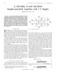
894 IEEE JOURNAL OF SOLID-STATE CIRCUITS, VOL. 46, NO. 4, APRIL 2011<br />
A <strong>300</strong>-<strong>GHz</strong> <strong>Fundamental</strong> <strong>Oscillator</strong><br />
<strong>in</strong> <strong>65</strong>-<strong>nm</strong> <strong>CMOS</strong> <strong>Technology</strong><br />
Abstract—<strong>Fundamental</strong> oscillators prove the existence of ga<strong>in</strong> at<br />
high frequencies, reveal<strong>in</strong>g the speed limitations of other circuits<br />
<strong>in</strong> a given technology. This paper presents an oscillator topology<br />
that employs feedback from an output stage to the core, thus<br />
achiev<strong>in</strong>g a high speed. The behavior of the proposed oscillator<br />
is formulated and simulations are used to compare it with the<br />
conventional cross-coupled pair circuit. Three prototypes realized<br />
<strong>in</strong> <strong>65</strong>-<strong>nm</strong> <strong>CMOS</strong> technology operate at 205 <strong>GHz</strong>, 240 <strong>GHz</strong>, and<br />
<strong>300</strong> <strong>GHz</strong>, each draw<strong>in</strong>g 3.7 mW from a 0.8-V supply.<br />
Index Terms—Carrier generation, frequency generation,<br />
frequency synthesis, microwave oscillators, millimeter-wave oscillators,<br />
spiral <strong>in</strong>ductors, transmission l<strong>in</strong>es, VCOs.<br />
I. INTRODUCTION<br />
F<br />
UNDAMENTAL oscillators serve as a benchmark of the<br />
technology, provid<strong>in</strong>g a more realistic measure of the atta<strong>in</strong>able<br />
speeds than do and of s<strong>in</strong>gle transistors. For<br />
example, such oscillators demonstrate the existence of ga<strong>in</strong> at<br />
high frequencies, pav<strong>in</strong>g the way for the design of other build<strong>in</strong>g<br />
blocks, e.g., amplifiers and frequency dividers. They also reveal<br />
accuracy limitations of passive and active device models.<br />
The speed of fundamental <strong>CMOS</strong> oscillators has grown by<br />
roughly a factor of 14 every ten years. As shown <strong>in</strong> Fig. 1<br />
[1]–[8], the oscillation frequency reached 1.4 <strong>GHz</strong> <strong>in</strong> 1988<br />
[1] and has steadily climbed s<strong>in</strong>ce. Also plotted are the ’s<br />
of the <strong>CMOS</strong> technologies around the time they have entered<br />
production. The ’s are obta<strong>in</strong>ed by simulations based on<br />
transistor models available for each generation. 1<br />
This paper describes an oscillator topology that achieves frequencies<br />
as high as <strong>300</strong> <strong>GHz</strong> <strong>in</strong> <strong>65</strong>-<strong>nm</strong> <strong>CMOS</strong> technology, the<br />
fastest reported <strong>in</strong> any silicon process. Orig<strong>in</strong>ally conceived for<br />
bimodal operation [10], [11] <strong>in</strong> the gigahertz range, the circuit<br />
also proves superior to the conventional cross-coupled oscillator<br />
(XCO) <strong>in</strong> terms of the maximum oscillation frequency. Specifically,<br />
it is shown that the proposed topology reduces the effect<br />
of the <strong>in</strong>ductor capacitance by a factor of 2 and the load capacitance<br />
by a factor of 4.<br />
Manuscript received August 23, 2010; revised November 15, 2010; accepted<br />
December 15, 2010. Date of publication March 03, 2011; date of current version<br />
March 25, 2011. This paper was approved by Guest Editor Ajith Amerasekera.<br />
The author is with the Electrical Eng<strong>in</strong>eer<strong>in</strong>g Department, University of California,<br />
Los Angeles, CA 90095-1594 USA (e-mail: razavi@ee.ucla.edu).<br />
Color versions of one or more of the figures <strong>in</strong> this paper are available onl<strong>in</strong>e<br />
at http://ieeexplore.ieee.org.<br />
Digital Object Identifier 10.1109/JSSC.2011.2108122<br />
1 The measured � ’s reported <strong>in</strong> [9] for 90-<strong>nm</strong> and <strong>65</strong>-<strong>nm</strong> devices are approximately<br />
equal to 140 <strong>GHz</strong> and 180 <strong>GHz</strong>, respectively, suggest<strong>in</strong>g that the<br />
simulation overestimates the latter.<br />
Behzad Razavi, Fellow, IEEE<br />
0018-9200/$26.00 © 2011 IEEE<br />
Fig. 1. Historical growth of fundamental oscillation frequency <strong>in</strong> <strong>CMOS</strong><br />
technology.<br />
Section II provides a brief overview of oscillation frequency<br />
limitations. Section III presents the proposed oscillator, formulates<br />
its behavior, and compares its maximum speed with<br />
that of the XCO. Section IV describes the prototype design and<br />
Section V summarizes the experimental results.<br />
II. BACKGROUND<br />
A. <strong>Fundamental</strong> and Superharmonic <strong>Oscillator</strong>s<br />
High-frequency periodic waveforms can be derived directly<br />
from a fundamental oscillator or, through nonl<strong>in</strong>ear operation,<br />
from a “superharmonic” oscillator. Examples of the latter <strong>in</strong>clude<br />
“push-push” topologies (where the second harmonic is<br />
sensed) or “edge-comb<strong>in</strong><strong>in</strong>g” arrangements [12], also known<br />
as “l<strong>in</strong>ear superposition” [13] or “ -push” oscillators [14]. Of<br />
course, given a fundamental oscillator, one can always extract a<br />
higher harmonic us<strong>in</strong>g one of these techniques to obta<strong>in</strong> a proportionally<br />
higher frequency. However, the two oscillator categories<br />
entail different system design implications. <strong>Fundamental</strong><br />
topologies readily provide differential and even quadrature outputs<br />
with relatively large voltage sw<strong>in</strong>gs, simplify<strong>in</strong>g the design<br />
of mixers and frequency dividers. Superharmonic oscillators,<br />
on the other hand, typically provide only a s<strong>in</strong>gle-ended output<br />
[13], [15] (except for that <strong>in</strong> [12]), requir<strong>in</strong>g bulky baluns, 90<br />
couplers, and buffers. In addition, the f<strong>in</strong>ite lower harmonics that<br />
leak to the output of a superharmonic topology may downconvert<br />
unwanted signals <strong>in</strong> a receiver.
RAZAVI: A <strong>300</strong>-<strong>GHz</strong> FUNDAMENTAL OSCILLATOR IN <strong>65</strong>-<strong>nm</strong> <strong>CMOS</strong> TECHNOLOGY 895<br />
Fig. 2. (a) Loss mechanisms <strong>in</strong> an oscillator, (b) simplified circuit of stage follow<strong>in</strong>g the oscillator.<br />
B. Oscillation at<br />
Def<strong>in</strong>ed as the frequency at which the unilateral power ga<strong>in</strong> of<br />
an active device falls to unity, is believed to set the upper<br />
bound on the oscillation frequency. It can be shown that for a<br />
MOSFET<br />
where and denotes the lumped equivalent<br />
value of the gate resistance [16]. We note that is, to the<br />
first order, <strong>in</strong>dependent of the dra<strong>in</strong>-bulk junction capacitance,<br />
. In fact, operation at assumes that the transistor is<br />
embedded with<strong>in</strong> a lossless network that unilateralizes the device,<br />
nulls the effect of , and matches the <strong>in</strong>put and output<br />
ports of the device for maximum power transfer. Unfortunately,<br />
the loss of on-chip passive networks prohibits a realistic oscillator<br />
to achieve . Simulations <strong>in</strong>dicate an of roughly<br />
380 <strong>GHz</strong> for <strong>65</strong>-<strong>nm</strong> nMOS devices with a dra<strong>in</strong> current density<br />
of 0.8 mA m(a of about 0.45 V). Found to be an optimum<br />
value for the oscillator designs described <strong>in</strong> Sections III<br />
and IV, this current density differs from the value of 0.3–0.4<br />
mA m recommended <strong>in</strong> [9] for maximum . This disparity<br />
can be attributed to the gate resistance, which directly impacts<br />
the maximum oscillation frequency but not the [16]. The accuracy<br />
of these simulations is limited by the quasi-static nature<br />
of the lumped BSIM4 model.<br />
C. Loss Mechanisms <strong>in</strong> <strong>Oscillator</strong>s<br />
At frequencies of hundreds of gigahertz, the design of oscillators<br />
must deal with several loss mechanisms. As conceptually<br />
illustrated <strong>in</strong> Fig. 2(a), the signal circulat<strong>in</strong>g with<strong>in</strong> the oscillator<br />
experiences (1) the loss of the resonat<strong>in</strong>g device, ; for a<br />
narrow frequency range, the loss is modeled by ;<br />
(2) the output resistance of the oscillat<strong>in</strong>g transistor(s), ; (3)<br />
the gate resistance of the oscillat<strong>in</strong>g transistor(s), ; and (4)<br />
the <strong>in</strong>put resistance of the follow<strong>in</strong>g stage, (typically, a<br />
buffer, a mixer, or a divider). The last mechanism can be formulated<br />
from the simplified diagram <strong>in</strong> Fig. 2(b), where encompasses<br />
all of the losses at node . At resonance<br />
(1)<br />
(2)<br />
Fig. 3. Gate resistance components.<br />
which reduces to if . We must<br />
add to to account for the gate resistance of<br />
.<br />
The key po<strong>in</strong>t here is that all of the mechanisms identified<br />
above produce comparable losses at several hundred gigahertz,<br />
forc<strong>in</strong>g operation well below . By contrast, oscillator design<br />
at tens of gigahertz must deal with primarily the loss of the<br />
<strong>in</strong>ductor.<br />
D. Effect of Gate Resistance<br />
As suggested by (1), the gate resistance proves a limit<strong>in</strong>g<br />
factor <strong>in</strong> high-frequency oscillator design. In deep-submicron<br />
technologies, arises from three components (Fig. 3): (1)<br />
the poly-metal contact resistance, (about 15 per contact),<br />
(2) the extr<strong>in</strong>sic resistance, , and (3) the distributed<br />
resistance, . With a sheet resistance of about 10<br />
and the required spac<strong>in</strong>g between the contact and the channel,<br />
(for <strong>nm</strong>), and hence .<br />
The lumped equivalent value of is given by<br />
[16]. It is desirable to contact the gate on both ends to reduce<br />
by a factor of 4, and m<strong>in</strong>imize the width so that<br />
is well below the unscalable component, . However,<br />
very narrow gates exhibit a longer equivalent channel length<br />
due to the distribution of dopants toward the shallow trench surround<strong>in</strong>g<br />
the transistor. As a compromise, <strong>in</strong> this work each gate<br />
f<strong>in</strong>ger has a of 0.4 m/60 <strong>nm</strong> and contacts on both ends,<br />
yield<strong>in</strong>g an equivalent lumped resistance of 30 .<br />
III. PROPOSED OSCILLATOR<br />
A. Evolution of Proposed <strong>Oscillator</strong><br />
Shown <strong>in</strong> Fig. 4(a), the proposed topology can be viewed as<br />
an oscillat<strong>in</strong>g core and a buffer, with some of the output energy<br />
of the latter coupled back to the former. We call this arrangement<br />
the “buffer-feedback oscillator” (BFO) and describe
896 IEEE JOURNAL OF SOLID-STATE CIRCUITS, VOL. 46, NO. 4, APRIL 2011<br />
Fig. 4. (a) Buffer-feedback oscillator. (b) Simplified model.<br />
a transformation that converts an XCO to the BFO. This evolutionary<br />
perspective ultimately allows a fair comparison of the<br />
two oscillators.<br />
As expla<strong>in</strong>ed <strong>in</strong> [17], the circuit of Fig. 4(a) can be decomposed<br />
as shown <strong>in</strong> Fig. 4(b), where represents the buffer<br />
transconductance, and its load tank, and the loss of<br />
the tank. If goes to <strong>in</strong>f<strong>in</strong>ity at an imag<strong>in</strong>ary frequency, then<br />
the circuit to the right of the dashed l<strong>in</strong>e can oscillate. Sett<strong>in</strong>g<br />
the denom<strong>in</strong>ator of to zero yields the oscillation frequencies<br />
as [17]<br />
and the startup condition as<br />
If and , then<br />
In this work, we consider only the lower mode, , at which<br />
the <strong>in</strong>ductor currents are <strong>in</strong> phase. The higher mode, , may<br />
entail greater <strong>in</strong>ductor losses due to the out-of-phase currents<br />
flow<strong>in</strong>g through the two <strong>in</strong>ductors. This mode can be present if<br />
the coupl<strong>in</strong>g polarity is <strong>in</strong>verted and has not been observed <strong>in</strong><br />
the prototypes described <strong>in</strong> Section IV.<br />
We can conceptually assume that <strong>in</strong> Fig. 4(b) cancels<br />
the loss of the second tank and the cross-coupled pair the loss of<br />
the first tank (modeled by ). In reality, this partition<strong>in</strong>g may<br />
not hold. Moreover, the tanks may not be identical. We return to<br />
these po<strong>in</strong>ts <strong>in</strong> the next section.<br />
(3)<br />
(4)<br />
(5)<br />
(6)<br />
We seek a transformation from the XCO to the BFO that reveals<br />
the speed advantage of the latter. The XCO/BFO transformation<br />
proceeds as follows. We beg<strong>in</strong> with the XCO and,<br />
as shown <strong>in</strong> Fig. 5(a), view its symmetric load <strong>in</strong>ductor as two<br />
equal mutually-coupled <strong>in</strong>ductors, and . Our goal is to derive<br />
the BFO without significantly alter<strong>in</strong>g the <strong>in</strong>ductor and its<br />
parasitics. Depicted <strong>in</strong> Fig. 5(b), the complete XCO models the<br />
<strong>in</strong>ductor’s parasitic capacitance by four components and its loss<br />
by . The capacitors denote the <strong>in</strong>put capacitance of the<br />
follow<strong>in</strong>g stage.<br />
We now decompose the load <strong>in</strong>ductor <strong>in</strong>to and , with<br />
their mutual coupl<strong>in</strong>g <strong>in</strong>tact [Fig. 5(c)]. Shown <strong>in</strong> Fig. 5(d),<br />
the circuit representation <strong>in</strong>cludes a resistance of <strong>in</strong> parallel<br />
with each <strong>in</strong>ductor. In the last step, we turn the two-<strong>in</strong>ductor<br />
(transformer) structure by 90 and tie its term<strong>in</strong>als to<br />
the cross-coupled pair and the output transistors [Fig. 5(e)].<br />
Note that the overall <strong>in</strong>ductor has rema<strong>in</strong>ed substantially unchanged.<br />
Fig. 5(f) shows the actual implementation us<strong>in</strong>g octagonal<br />
<strong>in</strong>ductors. The XCO and its descendent BFO are analyzed<br />
<strong>in</strong> the follow<strong>in</strong>g section to quantify their maximum oscillation<br />
frequencies.<br />
A by-product of the forego<strong>in</strong>g transformation is the reduction<br />
of the effect of the <strong>in</strong>ductor’s <strong>in</strong>terw<strong>in</strong>d<strong>in</strong>g capacitance. This capacitance<br />
susta<strong>in</strong>s a large voltage difference <strong>in</strong> Fig. 5(a)—due<br />
to differential excitation—but a small voltage difference <strong>in</strong><br />
Fig. 5(f) because the voltages at and and hence other<br />
adjacent po<strong>in</strong>ts along and are approximately equal.<br />
B. Analysis<br />
The objective of our analysis is to derive the oscillation<br />
startup conditions and frequencies of the XCO and the<br />
BFO, aim<strong>in</strong>g to prove that the latter can achieve a higher<br />
speed. In order to arrive at an <strong>in</strong>tuitively-appeal<strong>in</strong>g mathematically-tractable<br />
result, we make a number of simplify<strong>in</strong>g<br />
assumptions here.<br />
Our assumptions are as follows. 1) The gate-dra<strong>in</strong> overlap capacitance,<br />
, is neglected. 2) The transistor can be modeled
RAZAVI: A <strong>300</strong>-<strong>GHz</strong> FUNDAMENTAL OSCILLATOR IN <strong>65</strong>-<strong>nm</strong> <strong>CMOS</strong> TECHNOLOGY 897<br />
Fig. 5. (a) Cross-coupled oscillator with load <strong>in</strong>ductor viewed as two mutually-coupled <strong>in</strong>ductors, (b) XCO with <strong>in</strong>ductor parasitics, (c) decomposition of <strong>in</strong>ductors,<br />
(d) circuit model of (d), (e) reconfiguration to obta<strong>in</strong> the BFO, (f) actual implementation of BFO.<br />
Fig. 6. Simplified transistor model for hand calculations.<br />
by the lumped circuit shown <strong>in</strong> Fig. 6, where is absent<br />
but loss mechanisms are <strong>in</strong>cluded; (3) The <strong>in</strong>ductor(s) can be<br />
modeled by a lumped RLC circuit; (4) The <strong>in</strong>terconnects are<br />
short and hence their parasitics negligible; (5) If the two tanks<br />
<strong>in</strong> Fig. 4(b) are not identical but somewhat similar, then<br />
, where , .In<br />
addition, if , then we can assume the loss of each<br />
tank is modeled by an “average” resistance given by ;<br />
(6) To scale the transconductance of a transistor by a factor of<br />
, both the width (i.e., the number of gate f<strong>in</strong>gers) and the dra<strong>in</strong><br />
current are scaled by a factor of . The transistor-level simulations<br />
presented <strong>in</strong> the next section lift the first, second, and fifth<br />
assumptions and employ a BSIM4 model for the transistor.<br />
Our derivations will draw upon the two arrangements shown<br />
<strong>in</strong> Fig. 7. In Fig. 7(a)<br />
(7)<br />
In the simplified cross-coupled pair of Fig. 7(b)<br />
and hence<br />
If , then<br />
(8)<br />
(9)<br />
(10)<br />
(11)<br />
i.e., consists of a negative resistance of <strong>in</strong> parallel<br />
with a positive resistance of . Moreover,<br />
(12)<br />
as if were enlarged by a factor of . (The effect<br />
of and is taken <strong>in</strong>t account below.) Appendix I presents<br />
a more detailed analysis <strong>in</strong>clud<strong>in</strong>g the gate-dra<strong>in</strong> capacitance.<br />
Based on the above observations, we can reduce the XCO of<br />
Fig. 5(b) to the arrangement shown <strong>in</strong> Fig. 8(a), where denotes<br />
the small-signal transconductance of each transistor. Note<br />
that grounded (s<strong>in</strong>gle-ended) capacitances and resistances are
898 IEEE JOURNAL OF SOLID-STATE CIRCUITS, VOL. 46, NO. 4, APRIL 2011<br />
Fig. 7. Input admittance of (a) a simple CS stage, and (b) a cross-coupled pair.<br />
Fig. 8. Equivalent circuits of (a) XCO, and (b) BFO.<br />
halved and doubled, respectively, to convert them to float<strong>in</strong>g<br />
(differential) components. Also, the <strong>in</strong>put resistance of the follow<strong>in</strong>g<br />
stage is neglected. The oscillation startup condition is<br />
given by<br />
and the oscillation frequency by<br />
(13)<br />
(14)<br />
Similarly, the BFO of Fig. 5(e) can be simplified to the<br />
topology shown <strong>in</strong> Fig. 8(b), where the primes dist<strong>in</strong>guish the<br />
component values from those <strong>in</strong> Fig. 8(a). Note that is<br />
multiplied by 2 and the resistance due to divided by 2 so as<br />
to account for the output transistors. Assum<strong>in</strong>g<br />
and , and us<strong>in</strong>g the “averag<strong>in</strong>g” approximations mentioned<br />
above, we cancel the loss on the side by the negative<br />
resistive, , and that on the side by the voltage-dependent<br />
current source, . S<strong>in</strong>ce the parallel resistances on<br />
the two sides differ by one component, , we obta<strong>in</strong><br />
the average resistance as .<br />
Thus, the oscillation startup condition emerges as<br />
(15)<br />
In other words, if (13) holds for the XCO, then (15) must hold<br />
for the BFO that is derived from the XFO. Equation (15) suggests<br />
that must be approximately twice . If both the width<br />
(i.e., the number of gate f<strong>in</strong>gers) and the bias current of the transistors<br />
are doubled, then , , ,<br />
, and .<br />
We now obta<strong>in</strong> the oscillation frequency of the BFO us<strong>in</strong>g the<br />
“average” capacitances:<br />
(16)<br />
With the 2 transistor scal<strong>in</strong>g mentioned above, this expression<br />
reduces to<br />
(17)<br />
We observe from (14) and (17) that the BFO lowers the effect<br />
of <strong>in</strong>ductor parasitics by a factor of 2 and the next stage <strong>in</strong>put<br />
capacitance by a factor of 4. That is, the BFO speed advantage<br />
is more pronounced as the “fanout” seen by each oscillator <strong>in</strong>creases.<br />
2 However, as shown <strong>in</strong> the next section, circuit simulations<br />
us<strong>in</strong>g more realistic models and avoid<strong>in</strong>g the “averag<strong>in</strong>g”<br />
2 Intuitively, we can attribute the twofold reduction of g to the distribution<br />
of the <strong>in</strong>ductor parasitics over the two stages, and the fourfold reduction of g<br />
to the lower fanout (because all transistors <strong>in</strong> the BFO are doubled <strong>in</strong> width and<br />
bias current) and the “averag<strong>in</strong>g” effect with<strong>in</strong> the BFO.
RAZAVI: A <strong>300</strong>-<strong>GHz</strong> FUNDAMENTAL OSCILLATOR IN <strong>65</strong>-<strong>nm</strong> <strong>CMOS</strong> TECHNOLOGY 899<br />
Fig. 9. Simulated behavior of XCO and BFO as a function of (a) width of transistors <strong>in</strong> each oscillator (black l<strong>in</strong>e: ‡ aHXR "m, v aSH�r, v aUH�r;<br />
gray l<strong>in</strong>e: ‡ aI"m, v aRS�r, v aTS�r), (b) <strong>in</strong>ductance values, (c) <strong>in</strong>put transistor width of follow<strong>in</strong>g stage, (d) Q of <strong>in</strong>ductors.<br />
concept reveal that the BFO has about 18% speed advantage<br />
even with a small fanout. Also, as mentioned <strong>in</strong> Section III-A,<br />
the BFO reduces the effect of the <strong>in</strong>terw<strong>in</strong>d<strong>in</strong>g capacitance.<br />
The forego<strong>in</strong>g derivations have tacitly assumed that and<br />
are the same <strong>in</strong> (13) and (15). S<strong>in</strong>ce , the<br />
value of <strong>in</strong> (15) is <strong>in</strong> fact greater than half of <strong>in</strong> (13)<br />
[for a constant ]. This relaxes the required value<br />
of . On the other hand, the component <strong>in</strong> (15)<br />
is lower than <strong>in</strong> (13) (for a 2 transistor scal<strong>in</strong>g<br />
scenario), demand<strong>in</strong>g a higher . It is difficult to <strong>in</strong>corporate<br />
these dependencies <strong>in</strong> the above comparisons, but the two effects<br />
partially cancel.<br />
The BFO provides an even greater speed advantage if the<br />
<strong>in</strong>put resistance, , of the stage follow<strong>in</strong>g the oscillators is<br />
taken <strong>in</strong>to account. To this end, a component equal to is<br />
placed <strong>in</strong> parallel with the terms on the right-hand side of (13)<br />
and (15), dropp<strong>in</strong>g the former by a larger percentage than the<br />
latter. The simulation results <strong>in</strong> the next section embody these<br />
effects.<br />
C. Simulation Results<br />
Transistor-level simulations are carried out to compare the<br />
XCO and BFO oscillation frequencies as a function of four<br />
parameters: 1) the width of the oscillator transistors, (the<br />
four transistors <strong>in</strong> the BFO are identical); 2) the load <strong>in</strong>ductance;<br />
3) the <strong>in</strong>put transistor width of the subsequent stage, ; and<br />
4) the Q of the load <strong>in</strong>ductors. The simulations <strong>in</strong>clude a gate<br />
resistance of 30 for each 0.4- m-wide gate f<strong>in</strong>ger, a coupl<strong>in</strong>g<br />
factor of 0.4 between and <strong>in</strong> Figs. 5(a) and 5(e), and an<br />
Fig. 10. Simulated phase noise of XCO at 2<strong>65</strong> <strong>GHz</strong> (dashed l<strong>in</strong>e) and BFO at<br />
310 <strong>GHz</strong> (solid l<strong>in</strong>e).<br />
<strong>in</strong>ductor Q of 20 (except for the fourth case). The two <strong>in</strong>ductor<br />
segments, and , are unequal to reflect the choices <strong>in</strong> the<br />
prototypes.<br />
Fig. 9(a) plots the oscillation frequencies obta<strong>in</strong>ed from the<br />
first simulation as and the correspond<strong>in</strong>g dra<strong>in</strong> currents<br />
are reduced from 2 m so as to reach the maximum speed of<br />
each topology. Two cases have been considered to study the<br />
effect of the subsequent stage: (a) m, ,<br />
; (b) m, , .In<br />
both cases, the BFO exhibits a speed advantage of about 23%.
900 IEEE JOURNAL OF SOLID-STATE CIRCUITS, VOL. 46, NO. 4, APRIL 2011<br />
Fig. 11. Effect of contact and vias resistance <strong>in</strong> series with (a) load <strong>in</strong>ductor, or (b) dra<strong>in</strong> of transistor.<br />
Note that, as predicted <strong>in</strong> the previous section, the m<strong>in</strong>imum<br />
for the BFO (1.2 m) is twice that for the XCO. The higher<br />
speed accrues at a cost of fourfold <strong>in</strong>crease <strong>in</strong> power dissipation,<br />
an expected result because for frequencies approach<strong>in</strong>g the<br />
speed-power trade-off becomes heavily subl<strong>in</strong>ear.<br />
Depicted <strong>in</strong> Fig. 9(b) are the results as and vary. For<br />
each choice of the <strong>in</strong>ductors, the transistor widths <strong>in</strong> the oscillators<br />
are reduced to place the circuits at the edge of oscillation.<br />
Figure Fig. 9(c) plots the oscillation frequencies as the <strong>in</strong>put<br />
transistor width of the follow<strong>in</strong>g stage varies. As with the second<br />
simulation, for each choice of , the oscillators’ transistor<br />
widths are reduced to reach the edge of oscillation. We observe<br />
that the BFO speed advantage beg<strong>in</strong>s at about 18% for<br />
m and rises as <strong>in</strong>creases.<br />
Shown <strong>in</strong> Fig. 9(d) is the oscillators’ behavior as a function<br />
of the <strong>in</strong>ductor Q, with reduced for each value of Q to<br />
operate at the edge of oscillation. These results suggest that the<br />
BFO speed advantage beg<strong>in</strong>s at about 14% for and<br />
reaches about 20% for .<br />
Fig. 10 plots the simulated phase noise of the XCO at<br />
2<strong>65</strong> <strong>GHz</strong> and the BFO at 310 <strong>GHz</strong>. With the transformation<br />
described above, the former consumes one-fourth the power of<br />
the latter. An <strong>in</strong>ductor Q of 20 is assumed. We observe that the<br />
push towards the highest oscillation frequency does degrade<br />
the trade-off between phase noise and power dissipation.<br />
A. Realization and Model<strong>in</strong>g<br />
IV. PROTOTYPE DESIGN<br />
Three prototypes of the BFO have been realized with different<br />
<strong>in</strong>ductor designs. Implemented as s<strong>in</strong>gle-turn symmetric octagonal<br />
metal-9 structures, and are “nested” so as to susta<strong>in</strong><br />
a coupl<strong>in</strong>g factor of 0.4. The diameter of varies from 24 m<br />
to 40 m and that of from 32 mto48 m, provid<strong>in</strong>g nom<strong>in</strong>al<br />
values of , <strong>65</strong>, 85 pH and , 85, 105 pH.<br />
Each of the four transistors has a of 1.6 m/60 <strong>nm</strong> with a<br />
gate f<strong>in</strong>ger width of 0.4 m and a bias current of 1 mA.<br />
S<strong>in</strong>ce the transistors <strong>in</strong>corporate a gate f<strong>in</strong>ger width of<br />
0.4 m, the source/dra<strong>in</strong> areas accommodate only two contacts.<br />
As a result, the S/D series resistance due to only the contacts<br />
and vias becomes comparable with that of small <strong>in</strong>ductors.<br />
Fig. 11(a) illustrates a case where the current flow<strong>in</strong>g through a<br />
metal-9 spiral must descend through eight vias and one contact<br />
to reach the dra<strong>in</strong> of a transistor. If the gate of the next stage’s<br />
<strong>in</strong>put device senses the voltage at node , then (the<br />
sum of all via resistances) appears <strong>in</strong> series with the <strong>in</strong>ductor.<br />
On the other hand, as shown <strong>in</strong> Fig. 11(b), if the gate senses<br />
the voltage at node , albeit through another resistance, ,<br />
we expect the effect of to vanish. Simulations suggest<br />
that the “force and sense” (Kelv<strong>in</strong>) arrangement <strong>in</strong> Fig. 11(b)<br />
achieves 3% higher speed than the topology <strong>in</strong> Fig. 11(a) even<br />
though <strong>in</strong>troduces its own loss.<br />
The oscillation frequencies of the prototypes are predicted<br />
us<strong>in</strong>g the model<strong>in</strong>g methodology described <strong>in</strong> [18]. The entire<br />
layout, <strong>in</strong>clud<strong>in</strong>g the gate polysilicon f<strong>in</strong>gers (but exclud<strong>in</strong>g the<br />
source/dra<strong>in</strong> pn junctions), is imported <strong>in</strong>to HFSS and simulated<br />
as a multi-port network. The S-parameters thus obta<strong>in</strong>ed are<br />
then returned to Cadence and simulated with the BSIM4 (logic)<br />
model of the transistors. 3<br />
B. Design for Testability<br />
Direct measurement of oscillators at these frequencies is difficult<br />
for two reasons: (a) the small output transistors driv<strong>in</strong>g<br />
50-ohm <strong>in</strong>strumentation deliver very little power, and (b) the<br />
harmonic mixers available for these bands suffer from a high<br />
loss (50 to 60 dB). In this work, a harmonic mixer is placed<br />
on-chip to avoid driv<strong>in</strong>g 50 at hundreds of gigahertz. Shown<br />
<strong>in</strong> Fig. 12, the mixer multiplies a harmonic of an external <strong>in</strong>put<br />
by the oscillator output, generat<strong>in</strong>g an <strong>in</strong>termediate frequency<br />
(IF) <strong>in</strong> the range of 30 to 50 <strong>GHz</strong>. The IF output can thus be<br />
monitored directly on a spectrum analyzer with no need for external<br />
harmonic mixers. Of course, the on-chip mixer still suffers<br />
from tens of decibels of loss, but it only moderately loads<br />
3 The gate f<strong>in</strong>gers are modeled as metal l<strong>in</strong>es <strong>in</strong> HFSS and their resistance is<br />
<strong>in</strong>cluded <strong>in</strong> circuit simulations.
RAZAVI: A <strong>300</strong>-<strong>GHz</strong> FUNDAMENTAL OSCILLATOR IN <strong>65</strong>-<strong>nm</strong> <strong>CMOS</strong> TECHNOLOGY 901<br />
Fig. 12. On-chip harmonic mixer.<br />
Fig. 13. <strong>Oscillator</strong> die photo.<br />
the oscillator. In the mixer, m, m, and<br />
.<br />
To determ<strong>in</strong>e which harmonic of produces the observed<br />
IF, is varied by and the change <strong>in</strong> IF, , is measured.<br />
The ratio gives the harmonic order.<br />
V. EXPERIMENTAL RESULTS<br />
The oscillator prototypes have been fabricated <strong>in</strong> TSMC’s<br />
<strong>65</strong>-<strong>nm</strong> <strong>CMOS</strong> technology. Fig. 13 shows the active oscillator<br />
die area, which measures approximately m m.<br />
The nested <strong>in</strong>ductors are shown on top and the mixer load on<br />
the bottom.<br />
Two sets of measurements have been carried out. In the first<br />
set, the prototypes are mounted on a probe station, an external<br />
W-band <strong>in</strong>put is applied to the mixer, and the IF output is displayed<br />
on a spectrum analyzer. Fig. 14 shows an example with<br />
<strong>GHz</strong> and , reveal<strong>in</strong>g oscillation at <strong>300</strong>.5 <strong>GHz</strong>.<br />
(The sign of determ<strong>in</strong>es whether is equal to<br />
or .) The slight supply dependence of helps dist<strong>in</strong>guish<br />
the desired output from other mix<strong>in</strong>g components and<br />
also proves that the oscillator is not <strong>in</strong>jection-locked to the external<br />
<strong>in</strong>put. Inspection of other parts of the IF spectrum shows<br />
that the measured IF components <strong>in</strong>deed correspond to the first<br />
harmonic.<br />
Fig. 14. IF spectrum measured with � aVVXU <strong>GHz</strong>.<br />
In the second set, the output radiated by the prototypes is<br />
sensed by an FFT spectrometer [15] and the spectrum is constructed.<br />
Depicted <strong>in</strong> Fig. 15, the results agree with those of the<br />
first set, confirm<strong>in</strong>g that the mixer measurements have sensed<br />
the fundamental and not a higher harmonic.<br />
Fig. 16 plots the simulated and measured oscillation frequencies<br />
of theprototypes. It is <strong>in</strong>terest<strong>in</strong>g that the <strong>in</strong>tr<strong>in</strong>sic BSIM4<br />
capacitances are relatively accurate for frequencies approach<strong>in</strong>g<br />
. Table I summarizes the fundamental frequencies reported<br />
recently <strong>in</strong> <strong>CMOS</strong> technology.<br />
VI. CONCLUSION<br />
<strong>Fundamental</strong> oscillators can provide quantitative <strong>in</strong>sight <strong>in</strong>to<br />
the speed limitation of IC technologies. This paper has demonstrated<br />
the potential of the buffer-feedback oscillator for highfrequency<br />
operation. It is shown that the losses due to the <strong>in</strong>ductors,<br />
gate resistance, and the output resistance become significant<br />
at very high frequencies, mak<strong>in</strong>g it desirable to “distribute”<br />
them on multiple nodes—the dist<strong>in</strong>guish<strong>in</strong>g factor between the<br />
XCO and the BFO. Measurements <strong>in</strong>dicate oscillation frequencies<br />
from 205 <strong>GHz</strong> to <strong>300</strong> <strong>GHz</strong> <strong>in</strong> <strong>65</strong>-<strong>nm</strong> <strong>CMOS</strong> technology.<br />
APPENDIX I<br />
Consider the cross-coupled pair equivalent circuit shown <strong>in</strong><br />
Fig. 17. We have<br />
and hence<br />
(18)<br />
(19)<br />
s��‰ � a<br />
P@PC� ‚ Ag C@IC� ‚ Ag<br />
P‘IC‚ @g<br />
C‚<br />
Cg<br />
@g Cg<br />
A 3 “<br />
Ag g 3<br />
3X<br />
(20)
902 IEEE JOURNAL OF SOLID-STATE CIRCUITS, VOL. 46, NO. 4, APRIL 2011<br />
Fig. 15. Spectra obta<strong>in</strong>ed by a spectrometer for the (a) 240-<strong>GHz</strong> and (b) <strong>300</strong>-<strong>GHz</strong> prototypes.<br />
Fig. 16. Simulated and measured oscillation frequencies of the prototypes.<br />
TABLE I<br />
RECENT FUNDAMENTAL OSCILLATION FREQUENCIES OBTAINED<br />
IN <strong>CMOS</strong> TECHNOLOGY<br />
If , then<br />
(21)<br />
i.e., consists of a negative resistance of <strong>in</strong><br />
parallel with a positive resistance equal to<br />
Fig. 17. Equivalent circuit of cross-coupled pair <strong>in</strong>clud<strong>in</strong>g gate-dra<strong>in</strong><br />
capacitance.<br />
and another positive resistance equal to<br />
. Moreover,<br />
s��‰ �%<br />
P@PC� ‚ Ag C@IC� ‚ Ag C‚ @g Cg Ag g 3<br />
P<br />
3X<br />
(22)<br />
as if were enlarged by a factor of and by<br />
a factor of , with an additional capacitance equal to<br />
.<br />
ACKNOWLEDGMENT<br />
The author wishes to thank Harold Fetterman and Wei Liu<br />
of UCLA for spectrometer measurements. The author also<br />
gratefully acknowledges TSMC’s University Shuttle Program<br />
for chip fabrication.<br />
REFERENCES<br />
[1] M. Banu, “MOS oscillators with multi-decade tun<strong>in</strong>g range and gigahertz<br />
maximum speed,” IEEE J. Solid-State Circuits, vol. 23, pp.<br />
474–479, Apr. 1988.<br />
[2] B. Razavi et al., “A 3-<strong>GHz</strong> 25-mW <strong>CMOS</strong> phase-locked loop,” <strong>in</strong> Dig.<br />
of Symposium on VLSI Circuits, Jun. 1994, pp. 131–132.
RAZAVI: A <strong>300</strong>-<strong>GHz</strong> FUNDAMENTAL OSCILLATOR IN <strong>65</strong>-<strong>nm</strong> <strong>CMOS</strong> TECHNOLOGY 903<br />
[3] M. Soyuer et al., “A 3-V 4-<strong>GHz</strong> nMOS voltage-controlled oscillator<br />
with <strong>in</strong>tegrated resonator,” IEEE J. Solid-State Circuits, vol. 31, pp.<br />
2042–2045, Dec. 1996.<br />
[4] B. Kleveland et al., “Monolithic <strong>CMOS</strong> distributed amplifier and oscillator,”<br />
<strong>in</strong> ISSCC Dig. Tech. Papers, Feb. 1999, pp. 70–71.<br />
[5] H. Wang, “A 50-<strong>GHz</strong> VCO <strong>in</strong> 0.25- "m <strong>CMOS</strong>,” <strong>in</strong> ISSCC Dig. Tech.<br />
Papers, Feb. 2001, pp. 372–373.<br />
[6] L. Franca-Neto, R. Bishop, and B. Bloechel, “64 <strong>GHz</strong> and 100 <strong>GHz</strong><br />
VCOs <strong>in</strong> 90 <strong>nm</strong> <strong>CMOS</strong> us<strong>in</strong>g optimum pump<strong>in</strong>g method,” <strong>in</strong> ISSCC<br />
Dig. Tech. Papers, Feb. 2004, pp. 444–445.<br />
[7] E. Seok et al., “A 410 <strong>GHz</strong> <strong>CMOS</strong> push-push oscillator with an on-chip<br />
patch antenna,” <strong>in</strong> ISSCC Dig. Tech. Papers, Feb. 2008, pp. 472–473.<br />
[8] B. Razavi, “A <strong>300</strong>-<strong>GHz</strong> fundamental oscillator <strong>in</strong> <strong>65</strong>-<strong>nm</strong> <strong>CMOS</strong> technology,”<br />
<strong>in</strong> Symposium on VLSI Circuits Dig. of Tech. Papers, Jun.<br />
2010, pp. 113–114.<br />
[9] S. P. Vo<strong>in</strong>igescu et al., “<strong>CMOS</strong> SOCs at 100 <strong>GHz</strong>: System architectures,<br />
device characterization, and IC design examples,” <strong>in</strong> Proc.<br />
ISCAS, May 2007, pp. 1971–1974, and presentation slides.<br />
[10] B. Razavi, “Multi-decade carrier generation for cognitive radios,” <strong>in</strong><br />
VLSI Circuits Symp. Dig. Tech. Papers, Jun. 2009, pp. 120–121.<br />
[11] B. Catli and M. M. Hella, “A 1.94 to 2.55 <strong>GHz</strong>, 3.6 to 4.77 <strong>GHz</strong> tunable<br />
<strong>CMOS</strong> VCO based on double-tuned, double-driven coupled resonators,”<br />
IEEE Journal of Solid-State Circuits, vol. 44, pp. 2463–2477,<br />
Sep. 2009.<br />
[12] B. Razavi and J. Sung, “A 6-<strong>GHz</strong> 60-mW Bi<strong>CMOS</strong> phase-locked<br />
loop,” IEEE J. Solid-State Circuits, vol. 29, pp. 1560–15<strong>65</strong>, Dec. 1994.<br />
[13] D. Huang et al., “A 324 <strong>GHz</strong> <strong>CMOS</strong> frequency generator us<strong>in</strong>g a l<strong>in</strong>ear<br />
superposition technique,” <strong>in</strong> ISSCC Dig. Tech. Papers, Feb. 2008, pp.<br />
476–477.<br />
[14] B. Catli and M. Hella, “Triple-push operation for comb<strong>in</strong>ed oscillation/division<br />
functionality <strong>in</strong> millimeter-wave frequency synthesizers,”<br />
IEEE J. Solid-State Circuits, vol. 45, pp. 1575–1589, Aug. 2010.<br />
[15] E. Seok et al., “A 410 <strong>GHz</strong> <strong>CMOS</strong> push-push oscillator with an on-chip<br />
patch antenna,” <strong>in</strong> ISSCC Dig. Tech. Papers, Feb. 2008, pp. 472–473.<br />
[16] B. Razavi, R. H. Yan, and K. F. Lee, “Impact of distributed gate resistance<br />
on the performance of MOS devices,” IEEE Trans. Circuits and<br />
Systems—Part I, pp. 750–754, Nov. 1994.<br />
[17] B. Razavi, “Cognitive radio design challenges and techniques,” IEEE<br />
J. Solid-State Circuits, vol. 45, pp. 1542–1553, Aug. 2010.<br />
[18] C. K. Liang and B. Razavi, “Systematic transistor and <strong>in</strong>ductor model<strong>in</strong>g<br />
for millimeter-wave design,” IEEE J. Solid-State Circuits, vol.<br />
44, pp. 450–457, Feb. 2009.<br />
[19] Q. Gu et al., “Generat<strong>in</strong>g terahertz signals <strong>in</strong> <strong>65</strong> <strong>nm</strong> <strong>CMOS</strong> with negative-resistance<br />
resonator boost<strong>in</strong>g and selective harmonic suppression,”<br />
<strong>in</strong> Symposium on VLSI Circuits Dig. of Tech. Papers, Jun. 2010, pp.<br />
109–110.<br />
Behzad Razavi (M’90–SM’00–F’03) received the<br />
B.S.E.E. degree from Sharif University of <strong>Technology</strong>,<br />
Tehran, Iran, <strong>in</strong> 1985, and the M.S.E.E.<br />
and Ph.D.E.E. degrees from Stanford University,<br />
Stanford, CA, <strong>in</strong> 1988 and 1992, respectively.<br />
He was with AT&T Bell Laboratories and<br />
Hewlett-Packard Laboratories until 1996. S<strong>in</strong>ce<br />
1996, he has been Associate Professor and subsequently<br />
Professor of electrical eng<strong>in</strong>eer<strong>in</strong>g at<br />
University of California, Los Angeles. His current<br />
research <strong>in</strong>cludes wireless transceivers, frequency<br />
synthesizers, phase-lock<strong>in</strong>g and clock recovery for high-speed data communications,<br />
and data converters. Prof. Razavi was an Adjunct Professor at Pr<strong>in</strong>ceton<br />
University from 1992 to 1994, and at Stanford University <strong>in</strong> 1995. He served<br />
on the Technical Program Committees of the IEEE International Solid-State<br />
Circuits Conference (ISSCC) from 1993 to 2002 and VLSI Circuits Symposium<br />
from 1998 to 2002. He has also served as Guest Editor and Associate Editor<br />
of the IEEE JOURNAL OF SOLID-STATE CIRCUITS, IEEE TRANSACTIONS ON<br />
CIRCUITS AND SYSTEMS, and International Journal of High Speed Electronics.<br />
Prof. Razavi received the Beatrice W<strong>in</strong>ner Award for Editorial Excellence at<br />
the 1994 ISSCC, the best paper award at the 1994 European Solid-State Circuits<br />
Conference, the best panel award at the 1995 and 1997 ISSCC, the TRW<br />
Innovative Teach<strong>in</strong>g Award <strong>in</strong> 1997, the best paper award at the IEEE Custom<br />
Integrated Circuits Conference <strong>in</strong> 1998, and the McGraw-Hill First Edition of<br />
the Year Award <strong>in</strong> 2001. He was the co-recipient of both the Jack Kilby Outstand<strong>in</strong>g<br />
Student Paper Award and the Beatrice W<strong>in</strong>ner Award for Editorial Excellence<br />
at the 2001 ISSCC. He received the Lockheed Mart<strong>in</strong> Excellence <strong>in</strong><br />
Teach<strong>in</strong>g Award <strong>in</strong> 2006, the UCLA Faculty Senate Teach<strong>in</strong>g Award <strong>in</strong> 2007,<br />
and the CICC Best Invited Paper Award <strong>in</strong> 2009. He was also recognized as one<br />
of the top 10 authors <strong>in</strong> the 50-year history of ISSCC.<br />
Prof. Razavi is an IEEE Dist<strong>in</strong>guished Lecturer, a Fellow of IEEE, and the<br />
author of Pr<strong>in</strong>ciples of Data Conversion System Design (IEEE Press, 1995),<br />
RF Microelectronics (Prentice Hall, 1998) (translated to Ch<strong>in</strong>ese, Japanese, and<br />
Korean), Design of Analog <strong>CMOS</strong> Integrated Circuits (McGraw-Hill, 2001)<br />
(translated to Ch<strong>in</strong>ese, Japanese, and Korean), Design of Integrated Circuits for<br />
Optical Communications (McGraw-Hill, 2003), and <strong>Fundamental</strong>s of Microelectronics<br />
(Wiley, 2006) (translated to Korean and Portuguese), and the editor<br />
of Monolithic Phase-Locked Loops and Clock Recovery Circuits (IEEE Press,<br />
1996), and Phase-Lock<strong>in</strong>g <strong>in</strong> High-Performance Systems (IEEE Press, 2003).