A 2.6-GHz/5.2-GHz frequency synthesizer in 0.4-um ... - CiteSeerX
A 2.6-GHz/5.2-GHz frequency synthesizer in 0.4-um ... - CiteSeerX
A 2.6-GHz/5.2-GHz frequency synthesizer in 0.4-um ... - CiteSeerX

Create successful ePaper yourself
Turn your PDF publications into a flip-book with our unique Google optimized e-Paper software.
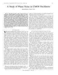
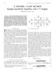
788 IEEE JOURNAL OF SOLID-STATE CIRCUITS, VOL. 35, NO. 5, MAY 2000<br />
A <strong>2.6</strong>-<strong>GHz</strong>/<strong>5.2</strong>-<strong>GHz</strong> Frequency Synthesizer <strong>in</strong><br />
<strong>0.4</strong>-"m CMOS Technology<br />
Abstract—This paper describes the design of a CMOS <strong>frequency</strong><br />
<strong>synthesizer</strong> target<strong>in</strong>g wireless local-area network applications <strong>in</strong><br />
the 5-<strong>GHz</strong> range. Based on an <strong>in</strong>teger- architecture, the <strong>synthesizer</strong><br />
produces a <strong>5.2</strong>-<strong>GHz</strong> output as well as the quadrature phases<br />
of a <strong>2.6</strong>-<strong>GHz</strong> carrier. Fabricated <strong>in</strong> a <strong>0.4</strong>- m digital CMOS technology,<br />
the circuit provides a channel spac<strong>in</strong>g of 23.5 MHz at <strong>5.2</strong><br />
<strong>GHz</strong> while exhibit<strong>in</strong>g a phase noise of 115 dBc/Hz at <strong>2.6</strong> <strong>GHz</strong> and<br />
100 dBc/Hz at <strong>5.2</strong> <strong>GHz</strong> (both at 10-MHz offset). The reference<br />
sidebands are at 53 dBc at <strong>2.6</strong> <strong>GHz</strong>, and the power dissipation<br />
from a <strong>2.6</strong>-V supply is 47 mW.<br />
Index Terms—Frequency dividers, oscillators, phase-locked<br />
loops, RF circuits, <strong>synthesizer</strong>s, wireless transceivers.<br />
I. INTRODUCTION<br />
WIRELESS local area networks (WLAN’s) provide great<br />
flexibility <strong>in</strong> the communication <strong>in</strong>frastructure of environments<br />
such as hospitals, factories, and large office build<strong>in</strong>gs.<br />
While WLAN standards <strong>in</strong> the 2.4-<strong>GHz</strong> range have recently<br />
emerged <strong>in</strong> the market, the data rates supported by such systems<br />
are limited to a few megabits per second. By contrast, a<br />
n<strong>um</strong>ber of standards have been def<strong>in</strong>ed <strong>in</strong> the 5-<strong>GHz</strong> range that<br />
allow data rates greater than 20 Mb/s, offer<strong>in</strong>g attractive solutions<br />
for real-time imag<strong>in</strong>g, multimedia, and high-speed video<br />
applications. One of these standards is high-performance radio<br />
LAN (HIPERLAN) [1].<br />
HIPERLAN operates across 5.15–5.30 <strong>GHz</strong> and provides a<br />
channel bandwidth of 23.5 MHz with Gaussian m<strong>in</strong>im<strong>um</strong> shift<br />
key<strong>in</strong>g (GMSK) modulation. The receiver sensitivity must exceed<br />
70 dBm.<br />
This paper presents the design of a <strong>frequency</strong> <strong>synthesizer</strong><br />
for 5-<strong>GHz</strong> WLAN applications. To target realistic specifications,<br />
HIPERLAN is chosen as the framework. Employ<strong>in</strong>g an<br />
<strong>in</strong>teger- architecture, the circuit generates a <strong>5.2</strong>-<strong>GHz</strong> output<br />
for the transmit path and the quadrature phases of a <strong>2.6</strong>-<strong>GHz</strong><br />
carrier for the receive path. Realized <strong>in</strong> a <strong>0.4</strong>- m CMOS technology,<br />
the <strong>synthesizer</strong> provides a channel spac<strong>in</strong>g of 23.5 MHz<br />
while dissipat<strong>in</strong>g 47 mW from a <strong>2.6</strong>-V supply. The phase noise<br />
at 10-MHz offset is equal to 115 dBc/Hz at <strong>2.6</strong> <strong>GHz</strong> and 100<br />
dBc/Hz at <strong>5.2</strong> <strong>GHz</strong>.<br />
Section II of this paper describes the <strong>synthesizer</strong> environment<br />
and general issues, and Section III <strong>in</strong>troduces the <strong>synthesizer</strong><br />
architecture. Section IV presents the design of each build<strong>in</strong>g<br />
block, and Section V s<strong>um</strong>marizes the experimental results.<br />
Manuscript received July 30, 1999; revised December 1, 1999.<br />
The authors are with the Department of Electrical Eng<strong>in</strong>eer<strong>in</strong>g, University of<br />
California, Los Angeles, CA 90095 USA (e-mail: razavi@ee.ucla.edu).<br />
Publisher Item Identifier S 0018-9200(00)02987-5.<br />
Christopher Lam and Behzad Razavi, Member, IEEE<br />
0018–9200/00$10.00 © 2000 IEEE<br />
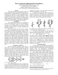
Fig. 1. Transceiver architecture.<br />
II. SYNTHESIZER ENVIRONMENT<br />
The design of a 5-<strong>GHz</strong> <strong>synthesizer</strong> <strong>in</strong> a <strong>0.4</strong>- m CMOS technology<br />
presents many difficulties at both the architecture and<br />
the circuit levels. The high center <strong>frequency</strong> of the voltage-controlled<br />
oscillator (VCO), the poor quality of <strong>in</strong>ductors due to<br />
sk<strong>in</strong> effect and substrate loss, the limited tun<strong>in</strong>g range, the nonl<strong>in</strong>earity<br />
of the VCO <strong>in</strong>put/output characteristic, the high speed<br />
required of the feedback divider, the mismatches <strong>in</strong> the charge<br />
p<strong>um</strong>p, and the implementation of the loop filter are among the<br />
issues encountered <strong>in</strong> this design.<br />
A <strong>0.4</strong>- m-long NMOS transistor <strong>in</strong> this technology achieves<br />
an of less than 15 <strong>GHz</strong> with a gate–source overdrive voltage<br />
of about 400 mV, a typical value <strong>in</strong> this design.<br />
Also, a 5-nH <strong>in</strong>ductor exhibits a self-resonance <strong>frequency</strong> of<br />
6.5 <strong>GHz</strong> and a of 5 at this <strong>frequency</strong>, <strong>in</strong>dicat<strong>in</strong>g that sk<strong>in</strong><br />
effect and substrate loss are much more significant at <strong>5.2</strong> <strong>GHz</strong><br />
than at <strong>2.6</strong> <strong>GHz</strong>. The technology offers no high-density l<strong>in</strong>ear<br />
capacitors, creat<strong>in</strong>g difficulty <strong>in</strong> the design of the loop filter.<br />
The forego<strong>in</strong>g limitations make it necessary that the transceiver<br />
and the <strong>synthesizer</strong> be designed concurrently so as to<br />
relax some of the <strong>synthesizer</strong> requirements. Fig. 1 shows the<br />
transceiver architecture and its <strong>in</strong>terface with the <strong>synthesizer</strong>.<br />
The receive path consists of two downconversion stages, each<br />
us<strong>in</strong>g a local oscillator (LO) <strong>frequency</strong> of <strong>2.6</strong> <strong>GHz</strong>, and the<br />
transmit path modulates the VCO by the Gaussian-filtered baseband<br />
data, produc<strong>in</strong>g a GMSK output.<br />
An important feature of this architecture is that the <strong>synthesizer</strong><br />
is shared between the transmitter and the receiver, reduc<strong>in</strong>g<br />
the system complexity substantially. This is possible because<br />
HIPERLAN <strong>in</strong>corporates time-division duplex<strong>in</strong>g (TDD). Also,<br />
the transceiver requires the generation of the quadrature phases<br />
of the <strong>2.6</strong>-<strong>GHz</strong> carrier rather than the <strong>5.2</strong>-<strong>GHz</strong> output, a task<br />
readily accomplished by the <strong>synthesizer</strong> itself.
LAM AND RAZAVI: <strong>2.6</strong>-<strong>GHz</strong>/<strong>5.2</strong>-<strong>GHz</strong> FREQUENCY SYNTHESIZER 789<br />
Fig. 2. Synthesizer architecture.<br />
Fig. 3. Position of reference sidebands.<br />
III. SYNTHESIZER ARCHITECTURE<br />
The <strong>synthesizer</strong> is based on an <strong>in</strong>teger- phase-locked loop<br />
architecture (Fig. 2). The feedback divider senses the <strong>2.6</strong>-<strong>GHz</strong><br />
output because it is not possible to design a dual-modulus<br />
divider <strong>in</strong> <strong>0.4</strong>- m CMOS technology that operates at <strong>5.2</strong> <strong>GHz</strong><br />
reliably. Controlled by the digital channel-select <strong>in</strong>put, the<br />
220–225 circuit generates <strong>frequency</strong> steps of<br />
MHz <strong>in</strong> the <strong>2.6</strong>-<strong>GHz</strong> band and 23.5 MHz <strong>in</strong> the <strong>5.2</strong>-<strong>GHz</strong> band.<br />
A critical issue <strong>in</strong> the architecture of Fig. 2 is the nonl<strong>in</strong>earity<br />
of the VCO characteristic, i.e., the variation of the VCO ga<strong>in</strong>,<br />
, with the control voltage . This effect manifests itself<br />
<strong>in</strong> the loop settl<strong>in</strong>g behavior as well as the magnitude of the<br />
phase noise and reference sidebands at the output. The problem<br />
is partially resolved through the use of a correction circuit that<br />
adjusts the charge-p<strong>um</strong>p current accord<strong>in</strong>g to the value of<br />
[2].<br />
An <strong>in</strong>terest<strong>in</strong>g property of the architecture of Fig. 2 is the<br />
position of the reference spurs with respect to the ma<strong>in</strong> carrier.<br />
S<strong>in</strong>ce the reference <strong>frequency</strong> is half the channel spac<strong>in</strong>g, such<br />
spurs fall at the edge of the channel rather than at the center of<br />
the adjacent channel for both <strong>2.6</strong>- and <strong>5.2</strong>-<strong>GHz</strong> outputs (Fig. 3).<br />
S<strong>in</strong>ce the <strong>in</strong>terference energy received by the antenna is small<br />
at the edge, the maxim<strong>um</strong> allowable magnitude of the spurs can<br />
be quite higher than if the reference <strong>frequency</strong> were equal to<br />
23.5 MHz.<br />
IV. BUILDING BLOCKS<br />
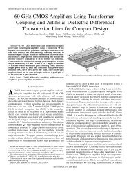
A. VCO<br />
The VCO core is based on two <strong>2.6</strong>-<strong>GHz</strong> coupled oscillators<br />
operat<strong>in</strong>g <strong>in</strong> quadrature, as shown <strong>in</strong> Fig. 4(a) [3], [4]. The fully<br />
differential topology of each oscillator raises the possibility of<br />
sens<strong>in</strong>g the common-source nodes A, B, C, or D as the <strong>5.2</strong>-<strong>GHz</strong><br />
output. In fact, s<strong>in</strong>ce the <strong>2.6</strong>-<strong>GHz</strong> oscillators operate <strong>in</strong> quadrature,<br />
the waveforms at A and B (or C and D) are 180 out of<br />
phase, thereby serv<strong>in</strong>g as a differential output at <strong>5.2</strong> <strong>GHz</strong>. With<br />
proper choice of device dimensions and bias current, a differential<br />
sw<strong>in</strong>g of 0.5 V can be achieved at this port. Note that if a<br />
<strong>frequency</strong> doubler were used, the output would be s<strong>in</strong>gle-ended<br />
and difficult to convert to differential form at such a high <strong>frequency</strong>.<br />
The tun<strong>in</strong>g of the oscillator poses several difficulties: the varactor<br />
diode must exhibit a small series resistance and rema<strong>in</strong><br />
reverse-biased even with large sw<strong>in</strong>gs <strong>in</strong> the oscillator, and the<br />
varactor capacitance must be large enough to yield the required<br />
tun<strong>in</strong>g range, but at the cost of <strong>in</strong>creas<strong>in</strong>g the power dissipation<br />
or the phase noise. This design <strong>in</strong>corporates a p -n diode <strong>in</strong>side<br />
an n-well and strapped with metal to reduce the n-well series<br />
resistance [4]. Such a structure suffers from a large parasitic<br />
n-well/substrate capacitance, mak<strong>in</strong>g it desirable to connect the<br />
anode of the diode to the oscillator. This is accomplished as illustrated<br />
<strong>in</strong> Fig. 4(b), where only one of the two oscillators is<br />
shown for clarity. Here, the control voltage varies the dc potential<br />
at nodes and by vary<strong>in</strong>g the on-resistance of .<br />
However, the sharp variation of the on-resistance of leads<br />
to significant change <strong>in</strong> the ga<strong>in</strong> of the VCO. To make the transition<br />
smoother, another transistor, , <strong>in</strong> series with a resistor<br />
is added as shown <strong>in</strong> Fig. 4(c). Transistor serves as a clamp,<br />
keep<strong>in</strong>g the tail current source <strong>in</strong> saturation. Otherwise, the oscillator<br />
may turn off dur<strong>in</strong>g <strong>synthesizer</strong> loop transients.<br />
S<strong>in</strong>ce the m<strong>in</strong>im<strong>um</strong> voltage at node is only a few hundred<br />
millivolts above ground, an NMOS differential pair cannot<br />
directly sense the <strong>5.2</strong>-<strong>GHz</strong> signal at this node. Instead, a<br />
common-gate stage is used [Fig. 4(d)]. But if is constant,<br />
then turns off for low values of . Modify<strong>in</strong>g the circuit<br />
as shown <strong>in</strong> Fig. 4(e) ensures that the common-gate stage<br />
carries a constant bias current across the full tun<strong>in</strong>g range.<br />
The choice of the <strong>in</strong>ductors and capacitance of the varactors<br />
entails a compromise between the phase noise and the tun<strong>in</strong>g<br />
range. In this design, 7-nH <strong>in</strong>ductors are used, each contribut<strong>in</strong>g<br />
a parasitic capacitance of 120 fF. The cross-coupled transistors<br />
are relatively wide to ensure startup, yield<strong>in</strong>g approximately<br />
175 fF of gate-source capacitance. The differential pairs coupl<strong>in</strong>g<br />
the oscillators also load the tank. As a result, the varactor<br />
capacitance for <strong>2.6</strong>-<strong>GHz</strong> operation must not exceed 160 fF.<br />
The <strong>in</strong>ductors are realized as stacked spirals [5] made of metal<br />
4 and metal 3 with a width of 6 m. S<strong>in</strong>ce the tun<strong>in</strong>g range<br />
is <strong>in</strong>evitably narrow, it is critical to predict the oscillation <strong>frequency</strong><br />
accurately. A distributed model is used for each <strong>in</strong>ductor,<br />
yield<strong>in</strong>g an error of only a few percent <strong>in</strong> the measured <strong>frequency</strong><br />
of oscillation.<br />
B. Frequency Divider<br />
The design of a <strong>2.6</strong>-<strong>GHz</strong> programmable divider with a reasonable<br />
power dissipation <strong>in</strong> <strong>0.4</strong>- m CMOS technology is quite<br />
difficult. A n<strong>um</strong>ber of circuit techniques are <strong>in</strong>troduced <strong>in</strong> this<br />
work to ameliorate the power–speed tradeoff.<br />
The divider is based on a pulse-swallow topology. Shown <strong>in</strong><br />
Fig. 5(a) is a conventional implementation, consist<strong>in</strong>g of a dualmodulus<br />
prescaler, a fixed-ratio program counter, and a programmable<br />
swallow counter. The RS latch is typically <strong>in</strong>cluded<br />
<strong>in</strong> the swallow counter and is drawn explicitly here for clarity.<br />
The prescaler beg<strong>in</strong>s the operation by divid<strong>in</strong>g by 1 until<br />
the swallow counter is full. The RS latch is then set, chang<strong>in</strong>g
790 IEEE JOURNAL OF SOLID-STATE CIRCUITS, VOL. 35, NO. 5, MAY 2000<br />
Fig. 4. Evolution of the VCO topology.<br />
the prescaler modulus to and disabl<strong>in</strong>g the swallow counter.<br />
The division cont<strong>in</strong>ues until the program counter is full and the<br />
RS latch is reset. The overall divide ratio is therefore equal to<br />
.<br />
The pulse-swallow divider used <strong>in</strong> this work is shown <strong>in</strong><br />
Fig. 5(b). Here, the RS latch is followed by a D flip-flop to<br />
allow pipel<strong>in</strong><strong>in</strong>g of the prescaler modulus control signal. This<br />
modification is justified below. The overall divide ratio is now<br />
equal to 1. A critical decision <strong>in</strong> the design of the<br />
divider is the choice between low-sw<strong>in</strong>g current-steer<strong>in</strong>g logic<br />
and rail-to-rail CMOS logic. Simulations of the circuit with<br />
various values of , , and <strong>in</strong>dicate that the m<strong>in</strong>im<strong>um</strong> power<br />
dissipation occurs if the prescaler <strong>in</strong>corporates current steer<strong>in</strong>g,<br />
its output is converted to rail-to-rail sw<strong>in</strong>gs, and the rema<strong>in</strong>der<br />
of the circuit <strong>in</strong>corporates standard dynamic and static CMOS<br />
logic. The use of current steer<strong>in</strong>g <strong>in</strong> the prescaler also obviates<br />
the need for large oscillator sw<strong>in</strong>gs, sav<strong>in</strong>g power <strong>in</strong> the VCO<br />
buffer.<br />
The design of the 8/9 prescaler for <strong>2.6</strong>-<strong>GHz</strong> operation<br />
presents a great challenge. Shown <strong>in</strong> Fig. 6, the prescaler<br />
consists of a synchronous 2/3 circuit and two asynchronous<br />
2 circuits. In a conventional 2/3 realization [Fig. 7(a)],<br />
flip-flop FF is loaded by an OR gate, whereas FF is loaded<br />
by FF ,anAND gate, and an output buffer. S<strong>in</strong>ce FF limits the<br />
speed, the fanout of three <strong>in</strong>herent to this topology translates<br />
to substantial power dissipation. Furthermore, if the divider is<br />
implemented by current-steer<strong>in</strong>g circuits, the AND gate requires<br />
stacked logic and hence level-shift source followers. Both of<br />
these issues <strong>in</strong>tensify the power–speed tradeoff.<br />
The 2/3 circuit used <strong>in</strong> this work is shown <strong>in</strong> Fig. 7(b).<br />
Here, FF is loaded by a NOR gate and FF by a NOR gate and<br />
a buffer. Simulations <strong>in</strong>dicate that the reduction of the load capacitance<br />
of FF <strong>in</strong>creases the maxim<strong>um</strong> operat<strong>in</strong>g speed by approximately<br />
40%.<br />
The NOR/flip-flop comb<strong>in</strong>ation is realized as depicted <strong>in</strong><br />
Fig. 8. The resistors are made of n-well, and the bias voltage<br />
is generated to fall midway between the high and low levels of<br />
<strong>in</strong>puts and . The output of the prescaler drives a differential<br />
to s<strong>in</strong>gle-ended converter, produc<strong>in</strong>g rail-to-rail sw<strong>in</strong>gs for the<br />
rema<strong>in</strong>der of the divider.<br />
The divider of Fig. 5 <strong>in</strong>corporates pipel<strong>in</strong><strong>in</strong>g for the prescaler<br />
modulus control, thereby relax<strong>in</strong>g the m<strong>in</strong>im<strong>um</strong> delay require-
LAM AND RAZAVI: <strong>2.6</strong>-<strong>GHz</strong>/<strong>5.2</strong>-<strong>GHz</strong> FREQUENCY SYNTHESIZER 791<br />
Fig. 5. Pulse swallow divider. (a) Conventional topology. (b) Addition of<br />
pipel<strong>in</strong><strong>in</strong>g <strong>in</strong> the prescaler modulus control path.<br />
Fig. 6. Prescaler.<br />
ment <strong>in</strong> this path. Fig. 9 illustrates the issue. When the 9 operation<br />
of the prescaler is f<strong>in</strong>ished, the circuit would have at most<br />
seven cycles of to change the modulus to eight. In this particular<br />
prescaler, the tim<strong>in</strong>g budget is actually about five <strong>in</strong>put<br />
cycles—approximately 1.9 ns. Thus, with no pipel<strong>in</strong><strong>in</strong>g, the last<br />
pulse generated by the prescaler <strong>in</strong> the 9 mode must propagate<br />
through the level converter, the first 2 stage <strong>in</strong> the swallow<br />
counter, the subsequent logic, the RS latch, and the three-<strong>in</strong>put<br />
NOR gate <strong>in</strong> less than 1.9 ns. Such a delay constra<strong>in</strong>t necessitates<br />
the use of current steer<strong>in</strong>g <strong>in</strong> this path, rais<strong>in</strong>g the power<br />
dissipation and complicat<strong>in</strong>g the design. With pipel<strong>in</strong><strong>in</strong>g, on<br />
the other hand, the maxim<strong>um</strong> tolerable delay <strong>in</strong>creases to about<br />
eight <strong>in</strong>put cycles—approximately 3.1 ns.<br />
C. Charge P<strong>um</strong>p and Loop Filter<br />
Fig. 10 shows the charge p<strong>um</strong>p [6] and the loop filter. Here,<br />
and —rather than and —operate as switches.<br />
Thus, the problem of transistor charge <strong>in</strong>jection and clock<br />
feedthrough to the output is somewhat alleviated. In addition<br />
to these errors, up and down currents produced by the charge<br />
p<strong>um</strong>p may also create ripple on the control voltage. S<strong>in</strong>ce <strong>in</strong><br />
locked condition, and turn on at every phase comparison<br />
<strong>in</strong>stant, any mismatch between their magnitudes, duration,<br />
or absolute tim<strong>in</strong>g results <strong>in</strong> a net current that is drawn from<br />
the loop filter.<br />
Fig. 7. Divide-by-2/3 circuit: (a) conventional topology and (b) circuit used <strong>in</strong><br />
this work.<br />
Fig. 8. Implementation of NOR/flip-flop comb<strong>in</strong>ation.<br />
Fig. 9. Pipel<strong>in</strong><strong>in</strong>g <strong>in</strong> the prescaler modulus control path.<br />
Fig. 10. Charge p<strong>um</strong>p and loop filter.<br />
To appreciate the significance of these effects, let us consider<br />
some typical values <strong>in</strong> this design. If the reference sidebands are<br />
to be 50 dB below the carrier, then with <strong>GHz</strong>/V<br />
and MHz, the ripple amplitude must not exceed
792 IEEE JOURNAL OF SOLID-STATE CIRCUITS, VOL. 35, NO. 5, MAY 2000<br />
Fig. 11. (a) Addition of correction circuit to charge p<strong>um</strong>p. (b) Simple fold<strong>in</strong>g circuit. (c) Fold<strong>in</strong>g circuit with one reference voltage.<br />
75 V. 1 This <strong>in</strong>dicates that great attention must be paid to the<br />
design of the phase/<strong>frequency</strong>, the charge p<strong>um</strong>p, and the loop<br />
filter so as to m<strong>in</strong>imize the above errors.<br />
Another source of ripple <strong>in</strong> the control voltage is the low<br />
output impedance of and <strong>in</strong> Fig. 10, especially as<br />
reaches with<strong>in</strong> a few hundred millivolts of the rails. This effect<br />
creates additional mismatch between the up and down currents<br />
as a function of , potentially lead<strong>in</strong>g to larger reference<br />
sidebands near the ends of the tun<strong>in</strong>g range. Transistors<br />
and degenerate and , respectively, alleviat<strong>in</strong>g<br />
this issue (another advantage of this topology over the standard<br />
charge-p<strong>um</strong>p configuration).<br />
The addition of <strong>in</strong> the circuit of Fig. 10 to suppress the<br />
ripple potentially degrades the stability of the loop. Simulations<br />
suggest that for , the settl<strong>in</strong>g time <strong>in</strong>creases negligibly.<br />
In this design, pF, pF, and k .<br />
The two capacitors can be realized by either MOSFET’s or polymetal<br />
sandwiches, a choice determ<strong>in</strong>ed by the control voltage<br />
range. To achieve the maxim<strong>um</strong> tun<strong>in</strong>g range, must approach<br />
the supply and ground rails, demand<strong>in</strong>g a reasonable capacitor<br />
l<strong>in</strong>earity across this range. MOS capacitors, however, exhibit<br />
substantial change as their gate-source voltage falls below<br />
the threshold. Even a parallel comb<strong>in</strong>ation of an NMOS capacitor<br />
(connected to ground) and a PMOS capacitor (connected to<br />
) suffers from a two-fold variation as goes from zero<br />
1 The ripple is approximated by a s<strong>in</strong>usoid here. In a more rigorous method,<br />
the ripple can be expressed as a Fourier series [7].<br />
to . For this reason, and are formed as poly-metal<br />
sandwiches (albeit with much less density than MOS capacitors).<br />
Another issue <strong>in</strong> the design of the loop filter of Fig. 10 relates<br />
to the thermal noise produced by . Low-pass filtered by<br />
and , this noise modulates the VCO, rais<strong>in</strong>g the output phase<br />
noise. The thermal noise on the control voltage per unit bandwidth<br />
is given by<br />
where denotes the noise density of . From the<br />
narrow-band <strong>frequency</strong> modulation theory [8], we know that<br />
if a s<strong>in</strong>usoid with a peak amplitude and <strong>frequency</strong><br />
modulates a VCO, the output sidebands fall at rad/s below<br />
and above the carrier <strong>frequency</strong> and exhibit a peak amplitude<br />
of . Approximat<strong>in</strong>g the noise per unit bandwidth<br />
<strong>in</strong> (1) by a s<strong>in</strong>usoid, we obta<strong>in</strong> the output relative phase<br />
noise per unit bandwidth at an offset <strong>frequency</strong> as<br />
(1)<br />
(2)
LAM AND RAZAVI: <strong>2.6</strong>-<strong>GHz</strong>/<strong>5.2</strong>-<strong>GHz</strong> FREQUENCY SYNTHESIZER 793<br />
Fig. 12. Die photograph.<br />
With the values chosen <strong>in</strong> this design, the output phase noise<br />
reaches 138 dBc/Hz at 10-MHz offset for<br />
<strong>GHz</strong>/V. While it is desirable to reduce the value of , the required<br />
<strong>in</strong>crease <strong>in</strong> leads to a severe area penalty because of<br />
the low density of the poly-metal capacitors. Note that s<strong>in</strong>ce the<br />
stability factor ,if is,<br />
say, halved, then must be quadrupled to ma<strong>in</strong>ta<strong>in</strong> constant<br />
(for a given charge-p<strong>um</strong>p current).<br />
D. Correction Circuit<br />
The ga<strong>in</strong> of the VCO varies substantially across the tun<strong>in</strong>g<br />
range, result<strong>in</strong>g <strong>in</strong> considerable change <strong>in</strong> the settl<strong>in</strong>g behavior.<br />
As depicted <strong>in</strong> Fig. 11(a), it is desirable to vary the charge-p<strong>um</strong>p<br />
current, , such that the product of and and<br />
hence rema<strong>in</strong> relatively constant. Rather than use piecewise<br />
l<strong>in</strong>earization [2], this work <strong>in</strong>corporates an analog fold<strong>in</strong>g technique.<br />
Fig. 11(b) shows a possible solution. Here and<br />
are off if is well below 1.1 V and hence .As<br />
approaches 1.1 V, turns on while is off. Thus, drops,<br />
reach<strong>in</strong>g a low value as carries most of and anegligible<br />
current. As approaches and exceeds 1.3 V, turns<br />
on and eventually returns to . This design actually utilizes<br />
the topology shown <strong>in</strong> Fig. 11(c), where only one reference<br />
voltage is required and each differential pair provides a built-<strong>in</strong><br />
offset by virtue of skewed device dimensions. The characteristic<br />
is similar to that shown for Fig. 11(b), with<br />
rent mirrors <strong>in</strong> the charge p<strong>um</strong>p.<br />
driv<strong>in</strong>g the cur-<br />
The reference voltage of 1.2 V <strong>in</strong> Fig. 11(c) ass<strong>um</strong>es that<br />
the ga<strong>in</strong> of the VCO reaches its maxim<strong>um</strong> at V.<br />
This value is somewhat process- and temperature-dependent,<br />
limit<strong>in</strong>g (accord<strong>in</strong>g to simulations) the suppression of the VCO<br />
nonl<strong>in</strong>earity to about one order of magnitude.<br />
V. EXPERIMENTAL RESULTS<br />
The <strong>frequency</strong> <strong>synthesizer</strong> has been fabricated <strong>in</strong> a <strong>0.4</strong>- m<br />
digital CMOS technology. All of the <strong>in</strong>ductors and capacitors<br />
are <strong>in</strong>cluded on the chip. Fig. 12 is a photograph of the die,<br />
which measures 1.75 1.15 mm . The circuit has been tested<br />
with a <strong>2.6</strong>-V supply.<br />
Figs. 13(a) and (b) depict the output spectra <strong>in</strong> the locked<br />
condition. The phase noise at 10-MHz offset is equal to 115<br />
dBc/Hz at 2.5 <strong>GHz</strong> and 100 dBc/Hz at <strong>5.2</strong> <strong>GHz</strong>. A significant<br />
part of the phase noise at <strong>5.2</strong> <strong>GHz</strong> is attributed to the considerable<br />
loss of the output 50- buffer. Fig. 14 shows the <strong>2.6</strong>-<strong>GHz</strong><br />
output along with the reference sidebands. The sidebands are<br />
Fig. 13. Measured spectra at <strong>2.6</strong> and <strong>5.2</strong> <strong>GHz</strong> <strong>in</strong> locked condition.<br />
Fig. 14. Measured spectr<strong>um</strong> at <strong>2.6</strong> <strong>GHz</strong>.<br />
Fig. 15. Setup for settl<strong>in</strong>g time measurement.<br />
approximately 53 dB below the carrier. For the <strong>5.2</strong>-<strong>GHz</strong> output,<br />
the sidebands are buried under the noise floor.<br />
The settl<strong>in</strong>g behavior of the <strong>synthesizer</strong> has also been studied.<br />
Fig. 15 illustrates the setup, where the modulus of the feedback
794 IEEE JOURNAL OF SOLID-STATE CIRCUITS, VOL. 35, NO. 5, MAY 2000<br />
Fig. 16. Control voltage dur<strong>in</strong>g loop settl<strong>in</strong>g.<br />
TABLE I<br />
SYNTHESIZER PERFORMANCE<br />
divider is switched periodically and the control voltage is monitored.<br />
The 0.8-pF capacitor results from the trace on the pr<strong>in</strong>ted<br />
circuit board, and the active probe presents an <strong>in</strong>put capacitance<br />
of 2 pF. S<strong>in</strong>ce pF and pF, the addition of these<br />
parasitics markedly degrades the stability. Therefore, a 100-k<br />
resistor is placed <strong>in</strong> series with the active probe to mimic the<br />
role of and . The low-pass filter thus formed has a corner<br />
<strong>frequency</strong> comparable to the loop bandwidth, and the 0.8-pF capacitor<br />
still produces r<strong>in</strong>g<strong>in</strong>g <strong>in</strong> the time response. Fig. 16 shows<br />
the measured control voltage, <strong>in</strong>dicat<strong>in</strong>g a settl<strong>in</strong>g time on the<br />
order of 40 s.<br />
Table I s<strong>um</strong>marizes the measured performance of the <strong>synthesizer</strong>.<br />
VI. CONCLUSION<br />
The speed and quality of the devices available <strong>in</strong> an IC technology<br />
directly affect the choice of transceiver architectures,<br />
<strong>synthesizer</strong> topologies, and circuit configurations. In order to<br />
optimize the overall system performance, the transceiver and<br />
the <strong>synthesizer</strong> must be designed concurrently, with particular<br />
attention to the <strong>frequency</strong> plann<strong>in</strong>g.<br />
Design<strong>in</strong>g a multigigahertz <strong>synthesizer</strong> <strong>in</strong> <strong>0.4</strong>- m CMOS<br />
technology necessitates circuit techniques such as: 1) a quadrature<br />
VCO with <strong>in</strong>herent <strong>frequency</strong> doubl<strong>in</strong>g, 2) a dual-modulus<br />
divider with equalized fanout, 3) pipel<strong>in</strong><strong>in</strong>g <strong>in</strong> pulse-swallow<br />
counters, and 4) use of fold<strong>in</strong>g stages to compensate for<br />
nonl<strong>in</strong>earity <strong>in</strong> the VCO characteristic.<br />
REFERENCES<br />
[1] “Radio equipment and systems (RES); High performance radio local<br />
area network (HIPERLAN); Functional specification,” ETSI, Sophia<br />
Antipolis, France, ETSI TC-RES, July 1995.<br />
[2] J. Cran<strong>in</strong>ckx and M. S. J. Steyaert, “A fully <strong>in</strong>tegrated CMOS<br />
DCS-1800 <strong>frequency</strong> <strong>synthesizer</strong>,” IEEE J. Solid-State Circuits, vol.<br />
33, pp. 2054–2065, Dec. 1998.<br />
[3] A. Rofougaran et al., “A 900-MHz CMOS LC oscillator with quadrature<br />
outputs,” <strong>in</strong> ISSCC Dig. Tech. Papers, Feb. 1996, pp. 392–393.<br />
[4] B. Razavi, “A 1.8 <strong>GHz</strong> CMOS voltage-controlled oscillator,” <strong>in</strong> ISSCC<br />
Dig. Tech. Papers, Feb. 1997, pp. 388–389.<br />
[5] R. B. Merril et al., “Optimization of high <strong>in</strong>ductors for multi-level<br />
metal CMOS,” <strong>in</strong> Proc. IEDM, Dec. 1995, pp. 38.7.1–38.7.4.<br />
[6] J. Alvarez, H. Sanchez, and G. Gerosa, “A wide-band low-voltage PLL<br />
for PowerPC microprocessors,” IEEE J. Solid-State Circuits, vol. 30, pp.<br />
383–391, Apr. 1995.<br />
[7] B. Razavi, RF Microelectronics. Upper Saddle River, NJ: Prentice-<br />
Hall, 1998.<br />
[8] L. W. Couch, Digital and Analog Communication Systems, 4th<br />
ed. New York: Macmillan, 1993.<br />
Christopher Lam received the B.Sc. and M.Sc. degrees<br />
<strong>in</strong> electrical eng<strong>in</strong>eer<strong>in</strong>g from the University of<br />
California, Los Angeles, <strong>in</strong> 1997 and 1999, respectively.<br />
He is currently with the Wireless Communication<br />
Group, National Semiconductor, Santa Clara,<br />
CA. His <strong>in</strong>terests <strong>in</strong>clude phase-locked loops and<br />
communication circuits.<br />
Behzad Razavi (S’87–M’90) received the B.Sc. degree<br />
from Sharif University of Technology, Tehran,<br />
Iran, <strong>in</strong> 1985 and the M.Sc. and Ph.D. degrees from<br />
Stanford University, Stanford, CA, <strong>in</strong> 1988 and 1992,<br />
respectively, all <strong>in</strong> electrical eng<strong>in</strong>eer<strong>in</strong>g.<br />
He was with AT&T Bell Laboratories, Holmdel,<br />
NJ, and subsequently Hewlett-Packard Laboratories,<br />
Palo Alto, CA. S<strong>in</strong>ce September 1996, he has been<br />
an Associate Professor of electrical eng<strong>in</strong>eer<strong>in</strong>g at the<br />
University of California, Los Angeles. His current research<br />
<strong>in</strong>cludes wireless transceivers, <strong>frequency</strong> <strong>synthesizer</strong>s,<br />
phase-lock<strong>in</strong>g and clock recovery for high-speed data communications,<br />
and data converters. He was an Adjunct Professor at Pr<strong>in</strong>ceton University,<br />
Pr<strong>in</strong>ceton, NJ, from 1992 to 1994, and at Stanford University <strong>in</strong> 1995.<br />
He is a member of the Technical Program Committees of the Symposi<strong>um</strong> on<br />
VLSI Circuits and the International Solid-State Circuits Conference (ISSCC),<br />
<strong>in</strong> which he is Chair of the Analog Subcommittee. He is the author of Pr<strong>in</strong>ciples<br />
of Data Conversion System Design (New York: IEEE Press, 1995), RF Microelectronics<br />
(Englewood Cliffs, NJ: Prentice-Hall, 1998), and Design of Analog<br />
CMOS Integrated Circuits (New York: McGraw-Hill, 2000), and the editor of<br />
Monolithic Phase-Locked Loops and Clock Recovery Circuits (New York: IEEE<br />
Press, 1996).<br />
Dr. Razavi received the Beatrice W<strong>in</strong>ner Award for Editorial Excellence at the<br />
1994 ISSCC, the Best Paper Award at the 1994 European Solid-State Circuits<br />
Conference, the Best Panel Award at the 1995 and 1997 ISSCC, the TRW Innovative<br />
Teach<strong>in</strong>g Award <strong>in</strong> 1997, and the Best Paper Award at the IEEE Custom<br />
Integrated Circuits Conference <strong>in</strong> 1998. He has also served as Guest Editor and<br />
Associate Editor of the IEEE JOURNAL OF SOLID-STATE CIRCUITS and IEEE<br />
TRANSACTIONS ON CIRCUITS AND SYSTEMS.