A Commands - Documentation & Online Help - Autodesk
A Commands - Documentation & Online Help - Autodesk
A Commands - Documentation & Online Help - Autodesk

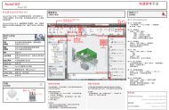
Create successful ePaper yourself
Turn your PDF publications into a flip-book with our unique Google optimized e-Paper software.
AutoCAD LT 2012 for Mac<br />
Command Reference Guide<br />
July 2011
© 2011 <strong>Autodesk</strong>, Inc. All Rights Reserved. Except as otherwise permitted by <strong>Autodesk</strong>, Inc., this publication, or parts thereof, may not<br />
be reproduced in any form, by any method, for any purpose.<br />
Certain materials included in this publication are reprinted with the permission of the copyright holder.<br />
Trademarks<br />
The following are registered trademarks or trademarks of <strong>Autodesk</strong>, Inc., and/or its subsidiaries and/or affiliates in the USA and other countries:<br />
3DEC (design/logo), 3December, 3December.com, 3ds Max, Algor, Alias, Alias (swirl design/logo), AliasStudio, Alias|Wavefront (design/logo),<br />
ATC, AUGI, AutoCAD, AutoCAD Learning Assistance, AutoCAD LT, AutoCAD Simulator, AutoCAD SQL Extension, AutoCAD SQL Interface,<br />
<strong>Autodesk</strong>, <strong>Autodesk</strong> Envision, <strong>Autodesk</strong> Intent, <strong>Autodesk</strong> Inventor, <strong>Autodesk</strong> Map, <strong>Autodesk</strong> MapGuide, <strong>Autodesk</strong> Streamline, AutoLISP, AutoSnap,<br />
AutoSketch, AutoTrack, Backburner, Backdraft, Built with ObjectARX (logo), Burn, Buzzsaw, CAiCE, Civil 3D, Cleaner, Cleaner Central, ClearScale,<br />
Colour Warper, Combustion, Communication Specification, Constructware, Content Explorer, Dancing Baby (image), DesignCenter, Design<br />
Doctor, Designer's Toolkit, DesignKids, DesignProf, DesignServer, DesignStudio, Design Web Format, Discreet, DWF, DWG, DWG (logo), DWG<br />
Extreme, DWG TrueConvert, DWG TrueView, DXF, Ecotect, Exposure, Extending the Design Team, Face Robot, FBX, Fempro, Fire, Flame, Flare,<br />
Flint, FMDesktop, Freewheel, GDX Driver, Green Building Studio, Heads-up Design, Heidi, HumanIK, IDEA Server, i-drop, ImageModeler, iMOUT,<br />
Incinerator, Inferno, Inventor, Inventor LT, Kaydara, Kaydara (design/logo), Kynapse, Kynogon, LandXplorer, Lustre, MatchMover, Maya,<br />
Mechanical Desktop, Moldflow, Moonbox, MotionBuilder, Movimento, MPA, MPA (design/logo), Moldflow Plastics Advisers, MPI, Moldflow<br />
Plastics Insight, MPX, MPX (design/logo), Moldflow Plastics Xpert, Mudbox, Multi-Master Editing, Navisworks, ObjectARX, ObjectDBX, Open<br />
Reality, Opticore, Opticore Opus, Pipeplus, PolarSnap, PortfolioWall, Powered with <strong>Autodesk</strong> Technology, Productstream, ProjectPoint, ProMaterials,<br />
RasterDWG, RealDWG, Real-time Roto, Recognize, Render Queue, Retimer,Reveal, Revit, Showcase, ShowMotion, SketchBook, Smoke, Softimage,<br />
Softimage|XSI (design/logo), Sparks, SteeringWheels, Stitcher, Stone, StudioTools, ToolClip, Topobase, Toxik, TrustedDWG, ViewCube, Visual,<br />
Visual LISP, Volo, Vtour, Wire, Wiretap, WiretapCentral, XSI, and XSI (design/logo).<br />
All other brand names, product names or trademarks belong to their respective holders.<br />
Disclaimer<br />
THIS PUBLICATION AND THE INFORMATION CONTAINED HEREIN IS MADE AVAILABLE BY AUTODESK, INC. "AS IS." AUTODESK, INC. DISCLAIMS<br />
ALL WARRANTIES, EITHER EXPRESS OR IMPLIED, INCLUDING BUT NOT LIMITED TO ANY IMPLIED WARRANTIES OF MERCHANTABILITY OR<br />
FITNESS FOR A PARTICULAR PURPOSE REGARDING THESE MATERIALS.<br />
Published by:<br />
<strong>Autodesk</strong>, Inc.<br />
111 McInnis Parkway<br />
San Rafael, CA 94903, USA
Contents<br />
Chapter 1 Introduction . . . . . . . . . . . . . . . . . . . . . . . . . . . . 1<br />
Introduction . . . . . . . . . . . . . . . . . . . . . . . . . . . . . . . . 1<br />
Using AutoCAD LT for Mac <strong>Documentation</strong> . . . . . . . . . . . . . 1<br />
Using This Reference . . . . . . . . . . . . . . . . . . . . . . . . . 1<br />
Executing <strong>Commands</strong> . . . . . . . . . . . . . . . . . . . . . 2<br />
References to Other Sections . . . . . . . . . . . . . . . . . . 5<br />
Chapter 2 <strong>Commands</strong> . . . . . . . . . . . . . . . . . . . . . . . . . . . . . 7<br />
<strong>Commands</strong> . . . . . . . . . . . . . . . . . . . . . . . . . . . . . . . . . 7<br />
3D <strong>Commands</strong> . . . . . . . . . . . . . . . . . . . . . . . . . . . . 7<br />
3DCONFIG (-3DCONFIG) . . . . . . . . . . . . . . . . . . . 7<br />
3DPAN . . . . . . . . . . . . . . . . . . . . . . . . . . . . . 8<br />
3DPOLY . . . . . . . . . . . . . . . . . . . . . . . . . . . . . 9<br />
3DZOOM . . . . . . . . . . . . . . . . . . . . . . . . . . . 10<br />
A <strong>Commands</strong> . . . . . . . . . . . . . . . . . . . . . . . . . . . . 11<br />
ABOUT . . . . . . . . . . . . . . . . . . . . . . . . . . . . 11<br />
ADDSELECTED . . . . . . . . . . . . . . . . . . . . . . . . 12<br />
ALIGN . . . . . . . . . . . . . . . . . . . . . . . . . . . . . 13<br />
ANNORESET . . . . . . . . . . . . . . . . . . . . . . . . . . 16<br />
ANNOUPDATE . . . . . . . . . . . . . . . . . . . . . . . . 16<br />
APERTURE . . . . . . . . . . . . . . . . . . . . . . . . . . . 17<br />
ARC . . . . . . . . . . . . . . . . . . . . . . . . . . . . . . 18<br />
AREA . . . . . . . . . . . . . . . . . . . . . . . . . . . . . . 26<br />
iii
iv | Contents<br />
ARRAY . . . . . . . . . . . . . . . . . . . . . . . . . . . . . 29<br />
ARRAYCLOSE . . . . . . . . . . . . . . . . . . . . . . . . . 33<br />
ARRAYEDIT . . . . . . . . . . . . . . . . . . . . . . . . . . 34<br />
ARRAYPATH . . . . . . . . . . . . . . . . . . . . . . . . . . 40<br />
ARRAYPOLAR . . . . . . . . . . . . . . . . . . . . . . . . . 44<br />
ARRAYRECT . . . . . . . . . . . . . . . . . . . . . . . . . . 46<br />
ATTACH . . . . . . . . . . . . . . . . . . . . . . . . . . . . 49<br />
ATTDEF . . . . . . . . . . . . . . . . . . . . . . . . . . . . 49<br />
ATTDISP . . . . . . . . . . . . . . . . . . . . . . . . . . . . 56<br />
ATTEDIT . . . . . . . . . . . . . . . . . . . . . . . . . . . . 58<br />
ATTEXT (-ATTEXT) . . . . . . . . . . . . . . . . . . . . . . 63<br />
ATTIPEDIT . . . . . . . . . . . . . . . . . . . . . . . . . . . 64<br />
ATTSYNC . . . . . . . . . . . . . . . . . . . . . . . . . . . 65<br />
AUDIT . . . . . . . . . . . . . . . . . . . . . . . . . . . . . 66<br />
AUTOCOMPLETE . . . . . . . . . . . . . . . . . . . . . . . 67<br />
B <strong>Commands</strong> . . . . . . . . . . . . . . . . . . . . . . . . . . . . 68<br />
BASE . . . . . . . . . . . . . . . . . . . . . . . . . . . . . . 68<br />
BATTMAN . . . . . . . . . . . . . . . . . . . . . . . . . . . 68<br />
BATTORDER . . . . . . . . . . . . . . . . . . . . . . . . . . 76<br />
BCLOSE . . . . . . . . . . . . . . . . . . . . . . . . . . . . 77<br />
BEDIT . . . . . . . . . . . . . . . . . . . . . . . . . . . . . 77<br />
BHATCH . . . . . . . . . . . . . . . . . . . . . . . . . . . . 81<br />
BLEND . . . . . . . . . . . . . . . . . . . . . . . . . . . . . 81<br />
BLIPMODE . . . . . . . . . . . . . . . . . . . . . . . . . . 83<br />
BLOCK . . . . . . . . . . . . . . . . . . . . . . . . . . . . . 84<br />
BMPOUT . . . . . . . . . . . . . . . . . . . . . . . . . . . 89<br />
BOUNDARY . . . . . . . . . . . . . . . . . . . . . . . . . . 90<br />
BREAK . . . . . . . . . . . . . . . . . . . . . . . . . . . . . 93<br />
BROWSER . . . . . . . . . . . . . . . . . . . . . . . . . . . 95<br />
BSAVE . . . . . . . . . . . . . . . . . . . . . . . . . . . . . 96<br />
BSAVEAS . . . . . . . . . . . . . . . . . . . . . . . . . . . . 96<br />
C <strong>Commands</strong> . . . . . . . . . . . . . . . . . . . . . . . . . . . . 98<br />
CAL . . . . . . . . . . . . . . . . . . . . . . . . . . . . . . 98<br />
CHAMFER . . . . . . . . . . . . . . . . . . . . . . . . . . 118<br />
CHANGE . . . . . . . . . . . . . . . . . . . . . . . . . . . 120<br />
CHPROP . . . . . . . . . . . . . . . . . . . . . . . . . . . 123<br />
CIRCLE . . . . . . . . . . . . . . . . . . . . . . . . . . . . 125<br />
CLEANSCREENON . . . . . . . . . . . . . . . . . . . . . . 128<br />
CLEANSCREENOFF . . . . . . . . . . . . . . . . . . . . . 128<br />
CLOSE . . . . . . . . . . . . . . . . . . . . . . . . . . . . 129<br />
CLOSEALL . . . . . . . . . . . . . . . . . . . . . . . . . . 129<br />
COLOR . . . . . . . . . . . . . . . . . . . . . . . . . . . . 130<br />
COMMANDLINE . . . . . . . . . . . . . . . . . . . . . . . 138<br />
COMMANDLINEHIDE . . . . . . . . . . . . . . . . . . . . 138<br />
CONSTRAINTBAR . . . . . . . . . . . . . . . . . . . . . . 139<br />
CONSTRAINTSETTINGS . . . . . . . . . . . . . . . . . . . 140
CONTENT . . . . . . . . . . . . . . . . . . . . . . . . . . 143<br />
CONTENTCLOSE . . . . . . . . . . . . . . . . . . . . . . 147<br />
CONVERT . . . . . . . . . . . . . . . . . . . . . . . . . . 147<br />
COPY . . . . . . . . . . . . . . . . . . . . . . . . . . . . . 148<br />
COPYBASE . . . . . . . . . . . . . . . . . . . . . . . . . . 150<br />
COPYCLIP . . . . . . . . . . . . . . . . . . . . . . . . . . 151<br />
COPYHIST . . . . . . . . . . . . . . . . . . . . . . . . . . 152<br />
CUI . . . . . . . . . . . . . . . . . . . . . . . . . . . . . . 152<br />
CUTCLIP . . . . . . . . . . . . . . . . . . . . . . . . . . . 160<br />
D <strong>Commands</strong> . . . . . . . . . . . . . . . . . . . . . . . . . . . 161<br />
DCDISPLAY . . . . . . . . . . . . . . . . . . . . . . . . . 161<br />
DDEDIT . . . . . . . . . . . . . . . . . . . . . . . . . . . 162<br />
DDPTYPE . . . . . . . . . . . . . . . . . . . . . . . . . . . 163<br />
DELAY . . . . . . . . . . . . . . . . . . . . . . . . . . . . 165<br />
DELCONSTRAINT . . . . . . . . . . . . . . . . . . . . . . 165<br />
DIM and DIM1 . . . . . . . . . . . . . . . . . . . . . . . . 165<br />
DIMALIGNED . . . . . . . . . . . . . . . . . . . . . . . . 168<br />
DIMANGULAR . . . . . . . . . . . . . . . . . . . . . . . . 171<br />
DIMARC . . . . . . . . . . . . . . . . . . . . . . . . . . . 175<br />
DIMBASELINE . . . . . . . . . . . . . . . . . . . . . . . . 176<br />
DIMBREAK . . . . . . . . . . . . . . . . . . . . . . . . . . 178<br />
DIMCENTER . . . . . . . . . . . . . . . . . . . . . . . . . 180<br />
DIMCONTINUE . . . . . . . . . . . . . . . . . . . . . . . 181<br />
DIMDIAMETER . . . . . . . . . . . . . . . . . . . . . . . 183<br />
DIMDISASSOCIATE . . . . . . . . . . . . . . . . . . . . . 185<br />
DIMEDIT . . . . . . . . . . . . . . . . . . . . . . . . . . . 185<br />
DIMINSPECT . . . . . . . . . . . . . . . . . . . . . . . . . 187<br />
DIMJOGGED . . . . . . . . . . . . . . . . . . . . . . . . . 191<br />
DIMJOGLINE . . . . . . . . . . . . . . . . . . . . . . . . 193<br />
DIMLINEAR . . . . . . . . . . . . . . . . . . . . . . . . . 194<br />
DIMORDINATE . . . . . . . . . . . . . . . . . . . . . . . 198<br />
DIMOVERRIDE . . . . . . . . . . . . . . . . . . . . . . . . 200<br />
DIMRADIUS . . . . . . . . . . . . . . . . . . . . . . . . . 201<br />
DIMREASSOCIATE . . . . . . . . . . . . . . . . . . . . . . 203<br />
DIMREGEN . . . . . . . . . . . . . . . . . . . . . . . . . 205<br />
DIMROTATED . . . . . . . . . . . . . . . . . . . . . . . . 206<br />
DIMSPACE . . . . . . . . . . . . . . . . . . . . . . . . . . 207<br />
DIMSTYLE . . . . . . . . . . . . . . . . . . . . . . . . . . 209<br />
DIMTEDIT . . . . . . . . . . . . . . . . . . . . . . . . . . 244<br />
DIST . . . . . . . . . . . . . . . . . . . . . . . . . . . . . 247<br />
DIVIDE . . . . . . . . . . . . . . . . . . . . . . . . . . . . 248<br />
DONUT . . . . . . . . . . . . . . . . . . . . . . . . . . . 250<br />
DRAGMODE . . . . . . . . . . . . . . . . . . . . . . . . . 251<br />
DRAWINGRECOVERY . . . . . . . . . . . . . . . . . . . . 252<br />
DRAWINGRECOVERYHIDE . . . . . . . . . . . . . . . . . 254<br />
DRAWORDER . . . . . . . . . . . . . . . . . . . . . . . . 254<br />
Contents | v
vi | Contents<br />
DSETTINGS . . . . . . . . . . . . . . . . . . . . . . . . . 255<br />
E <strong>Commands</strong> . . . . . . . . . . . . . . . . . . . . . . . . . . . . 271<br />
EATTEDIT . . . . . . . . . . . . . . . . . . . . . . . . . . 271<br />
Edit PGP . . . . . . . . . . . . . . . . . . . . . . . . . . . 276<br />
ELEV . . . . . . . . . . . . . . . . . . . . . . . . . . . . . 277<br />
ELLIPSE . . . . . . . . . . . . . . . . . . . . . . . . . . . . 278<br />
ERASE . . . . . . . . . . . . . . . . . . . . . . . . . . . . 282<br />
EXPLODE . . . . . . . . . . . . . . . . . . . . . . . . . . 283<br />
EXPORT . . . . . . . . . . . . . . . . . . . . . . . . . . . 285<br />
EXTEND . . . . . . . . . . . . . . . . . . . . . . . . . . . 286<br />
EXTERNALREFERENCES . . . . . . . . . . . . . . . . . . . 289<br />
EXTERNALREFERENCESCLOSE . . . . . . . . . . . . . . . 299<br />
F <strong>Commands</strong> . . . . . . . . . . . . . . . . . . . . . . . . . . . . 299<br />
FIELD . . . . . . . . . . . . . . . . . . . . . . . . . . . . . 299<br />
FILL . . . . . . . . . . . . . . . . . . . . . . . . . . . . . 302<br />
FILLET . . . . . . . . . . . . . . . . . . . . . . . . . . . . 302<br />
FIND . . . . . . . . . . . . . . . . . . . . . . . . . . . . . 306<br />
G <strong>Commands</strong> . . . . . . . . . . . . . . . . . . . . . . . . . . . 309<br />
GETENV . . . . . . . . . . . . . . . . . . . . . . . . . . . 309<br />
GRADIENT . . . . . . . . . . . . . . . . . . . . . . . . . . 310<br />
GRID . . . . . . . . . . . . . . . . . . . . . . . . . . . . . 311<br />
GROUP . . . . . . . . . . . . . . . . . . . . . . . . . . . . 312<br />
GROUPEDIT . . . . . . . . . . . . . . . . . . . . . . . . . 314<br />
H <strong>Commands</strong> . . . . . . . . . . . . . . . . . . . . . . . . . . . 315<br />
HATCH . . . . . . . . . . . . . . . . . . . . . . . . . . . . 315<br />
HATCHEDIT . . . . . . . . . . . . . . . . . . . . . . . . . 340<br />
HATCHGENERATEBOUNDARY . . . . . . . . . . . . . . . 344<br />
HATCHSETBOUNDARY . . . . . . . . . . . . . . . . . . . 344<br />
HATCHSETORIGIN . . . . . . . . . . . . . . . . . . . . . 345<br />
HATCHTOBACK . . . . . . . . . . . . . . . . . . . . . . . 346<br />
HELP . . . . . . . . . . . . . . . . . . . . . . . . . . . . . 346<br />
HIDE . . . . . . . . . . . . . . . . . . . . . . . . . . . . . 347<br />
HIDEOBJECTS . . . . . . . . . . . . . . . . . . . . . . . . 348<br />
HIDEPALETTES . . . . . . . . . . . . . . . . . . . . . . . . 349<br />
I <strong>Commands</strong> . . . . . . . . . . . . . . . . . . . . . . . . . . . . 349<br />
ID . . . . . . . . . . . . . . . . . . . . . . . . . . . . . . . 349<br />
IMAGE . . . . . . . . . . . . . . . . . . . . . . . . . . . . 350<br />
IMAGEADJUST (-IMAGEADJUST) . . . . . . . . . . . . . . 353<br />
IMAGEATTACH . . . . . . . . . . . . . . . . . . . . . . . 354<br />
IMAGECLIP . . . . . . . . . . . . . . . . . . . . . . . . . 357<br />
IMAGEQUALITY . . . . . . . . . . . . . . . . . . . . . . . 358<br />
INSERT . . . . . . . . . . . . . . . . . . . . . . . . . . . . 359<br />
INTERSECT . . . . . . . . . . . . . . . . . . . . . . . . . . 365<br />
ISOLATEOBJECTS . . . . . . . . . . . . . . . . . . . . . . 365<br />
ISOPLANE . . . . . . . . . . . . . . . . . . . . . . . . . . 366<br />
J <strong>Commands</strong> . . . . . . . . . . . . . . . . . . . . . . . . . . . . 367
JOIN . . . . . . . . . . . . . . . . . . . . . . . . . . . . . 367<br />
JPGOUT . . . . . . . . . . . . . . . . . . . . . . . . . . . 370<br />
L <strong>Commands</strong> . . . . . . . . . . . . . . . . . . . . . . . . . . . . 370<br />
LAYER . . . . . . . . . . . . . . . . . . . . . . . . . . . . 370<br />
LAYERCLOSE . . . . . . . . . . . . . . . . . . . . . . . . . 388<br />
LAYERP . . . . . . . . . . . . . . . . . . . . . . . . . . . . 388<br />
LAYERPMODE . . . . . . . . . . . . . . . . . . . . . . . . 389<br />
LAYFRZ . . . . . . . . . . . . . . . . . . . . . . . . . . . . 389<br />
LAYISO . . . . . . . . . . . . . . . . . . . . . . . . . . . . 390<br />
LAYLCK . . . . . . . . . . . . . . . . . . . . . . . . . . . 392<br />
LAYMCH . . . . . . . . . . . . . . . . . . . . . . . . . . . 392<br />
LAYMCUR . . . . . . . . . . . . . . . . . . . . . . . . . . 393<br />
LAYMRG (-LAYMRG) . . . . . . . . . . . . . . . . . . . . 394<br />
LAYOFF . . . . . . . . . . . . . . . . . . . . . . . . . . . . 395<br />
LAYOUT . . . . . . . . . . . . . . . . . . . . . . . . . . . 396<br />
LAYULK . . . . . . . . . . . . . . . . . . . . . . . . . . . 399<br />
LAYUNISO . . . . . . . . . . . . . . . . . . . . . . . . . . 399<br />
LEADER . . . . . . . . . . . . . . . . . . . . . . . . . . . 400<br />
LENGTHEN . . . . . . . . . . . . . . . . . . . . . . . . . 403<br />
LIMITS . . . . . . . . . . . . . . . . . . . . . . . . . . . . 405<br />
LINE . . . . . . . . . . . . . . . . . . . . . . . . . . . . . 406<br />
LINETYPE . . . . . . . . . . . . . . . . . . . . . . . . . . 408<br />
LIST . . . . . . . . . . . . . . . . . . . . . . . . . . . . . 413<br />
LOGFILEOFF . . . . . . . . . . . . . . . . . . . . . . . . . 414<br />
LOGFILEON . . . . . . . . . . . . . . . . . . . . . . . . . 414<br />
LTSCALE . . . . . . . . . . . . . . . . . . . . . . . . . . . 415<br />
LWEIGHT . . . . . . . . . . . . . . . . . . . . . . . . . . 415<br />
M <strong>Commands</strong> . . . . . . . . . . . . . . . . . . . . . . . . . . . 419<br />
MASSPROP . . . . . . . . . . . . . . . . . . . . . . . . . . 419<br />
MATCHCELL . . . . . . . . . . . . . . . . . . . . . . . . . 423<br />
MATCHPROP . . . . . . . . . . . . . . . . . . . . . . . . 424<br />
MEASURE . . . . . . . . . . . . . . . . . . . . . . . . . . 428<br />
MEASUREGEOM . . . . . . . . . . . . . . . . . . . . . . . 429<br />
MIRROR . . . . . . . . . . . . . . . . . . . . . . . . . . . 433<br />
MLEADER . . . . . . . . . . . . . . . . . . . . . . . . . . 435<br />
MLEADERALIGN . . . . . . . . . . . . . . . . . . . . . . . 438<br />
MLEADERCOLLECT . . . . . . . . . . . . . . . . . . . . . 439<br />
MLEADEREDIT . . . . . . . . . . . . . . . . . . . . . . . . 440<br />
MLEADERSTYLE . . . . . . . . . . . . . . . . . . . . . . . 442<br />
MODEL . . . . . . . . . . . . . . . . . . . . . . . . . . . . 451<br />
MOVE . . . . . . . . . . . . . . . . . . . . . . . . . . . . 451<br />
MREDO . . . . . . . . . . . . . . . . . . . . . . . . . . . 452<br />
MSPACE . . . . . . . . . . . . . . . . . . . . . . . . . . . 453<br />
MTEDIT . . . . . . . . . . . . . . . . . . . . . . . . . . . 453<br />
MTEXT . . . . . . . . . . . . . . . . . . . . . . . . . . . . 454<br />
MULTIPLE . . . . . . . . . . . . . . . . . . . . . . . . . . 479<br />
Contents | vii
viii | Contents<br />
MVIEW . . . . . . . . . . . . . . . . . . . . . . . . . . . . 479<br />
N <strong>Commands</strong> . . . . . . . . . . . . . . . . . . . . . . . . . . . 483<br />
NEW . . . . . . . . . . . . . . . . . . . . . . . . . . . . . 483<br />
O <strong>Commands</strong> . . . . . . . . . . . . . . . . . . . . . . . . . . . 484<br />
OBJECTSCALE . . . . . . . . . . . . . . . . . . . . . . . . 484<br />
OFFSET . . . . . . . . . . . . . . . . . . . . . . . . . . . . 488<br />
OOPS . . . . . . . . . . . . . . . . . . . . . . . . . . . . . 490<br />
OPEN . . . . . . . . . . . . . . . . . . . . . . . . . . . . . 491<br />
OPTIONS . . . . . . . . . . . . . . . . . . . . . . . . . . . 495<br />
ORTHO . . . . . . . . . . . . . . . . . . . . . . . . . . . . 511<br />
OSNAP . . . . . . . . . . . . . . . . . . . . . . . . . . . . 512<br />
OVERKILL . . . . . . . . . . . . . . . . . . . . . . . . . . 513<br />
P <strong>Commands</strong> . . . . . . . . . . . . . . . . . . . . . . . . . . . . 517<br />
PAGESETUP . . . . . . . . . . . . . . . . . . . . . . . . . 517<br />
PAGESETUPEDIT . . . . . . . . . . . . . . . . . . . . . . . 530<br />
PALETTEICONOFF . . . . . . . . . . . . . . . . . . . . . . 531<br />
PALETTEICONON . . . . . . . . . . . . . . . . . . . . . . 531<br />
PAN . . . . . . . . . . . . . . . . . . . . . . . . . . . . . . 532<br />
PARAMETERS (-PARAMETERS) . . . . . . . . . . . . . . . 535<br />
PASTECLIP . . . . . . . . . . . . . . . . . . . . . . . . . . 535<br />
PEDIT . . . . . . . . . . . . . . . . . . . . . . . . . . . . 536<br />
PLAN . . . . . . . . . . . . . . . . . . . . . . . . . . . . . 547<br />
PLINE . . . . . . . . . . . . . . . . . . . . . . . . . . . . . 548<br />
PLOT . . . . . . . . . . . . . . . . . . . . . . . . . . . . . 555<br />
PLOTSTAMP . . . . . . . . . . . . . . . . . . . . . . . . . 563<br />
PLOTSTYLE . . . . . . . . . . . . . . . . . . . . . . . . . 571<br />
PNGOUT . . . . . . . . . . . . . . . . . . . . . . . . . . . 577<br />
POINT . . . . . . . . . . . . . . . . . . . . . . . . . . . . 578<br />
POLYGON . . . . . . . . . . . . . . . . . . . . . . . . . . 579<br />
PREVIEW . . . . . . . . . . . . . . . . . . . . . . . . . . . 582<br />
PROPERTIES . . . . . . . . . . . . . . . . . . . . . . . . . 583<br />
PROPERTIESCLOSE . . . . . . . . . . . . . . . . . . . . . 590<br />
PSETUPIN . . . . . . . . . . . . . . . . . . . . . . . . . . 590<br />
PSPACE . . . . . . . . . . . . . . . . . . . . . . . . . . . . 591<br />
PUBLISH . . . . . . . . . . . . . . . . . . . . . . . . . . . 592<br />
PURGE . . . . . . . . . . . . . . . . . . . . . . . . . . . . 596<br />
Q <strong>Commands</strong> . . . . . . . . . . . . . . . . . . . . . . . . . . . 597<br />
QDIM . . . . . . . . . . . . . . . . . . . . . . . . . . . . 597<br />
QLEADER . . . . . . . . . . . . . . . . . . . . . . . . . . 598<br />
QNEW . . . . . . . . . . . . . . . . . . . . . . . . . . . . 604<br />
QSAVE . . . . . . . . . . . . . . . . . . . . . . . . . . . . 604<br />
QTEXT . . . . . . . . . . . . . . . . . . . . . . . . . . . . 605<br />
QUICKVIEW . . . . . . . . . . . . . . . . . . . . . . . . . 606<br />
QUIT . . . . . . . . . . . . . . . . . . . . . . . . . . . . . 608<br />
R <strong>Commands</strong> . . . . . . . . . . . . . . . . . . . . . . . . . . . . 609<br />
RAY . . . . . . . . . . . . . . . . . . . . . . . . . . . . . . 609
RECOVER . . . . . . . . . . . . . . . . . . . . . . . . . . 610<br />
RECTANG . . . . . . . . . . . . . . . . . . . . . . . . . . 611<br />
REDO . . . . . . . . . . . . . . . . . . . . . . . . . . . . . 612<br />
REDRAW . . . . . . . . . . . . . . . . . . . . . . . . . . . 613<br />
REFCLOSE . . . . . . . . . . . . . . . . . . . . . . . . . . 613<br />
REFEDIT . . . . . . . . . . . . . . . . . . . . . . . . . . . 614<br />
REFSET . . . . . . . . . . . . . . . . . . . . . . . . . . . . 620<br />
REGEN . . . . . . . . . . . . . . . . . . . . . . . . . . . . 621<br />
REGENALL . . . . . . . . . . . . . . . . . . . . . . . . . . 621<br />
REGION . . . . . . . . . . . . . . . . . . . . . . . . . . . 622<br />
RENAME . . . . . . . . . . . . . . . . . . . . . . . . . . . 623<br />
RESETBLOCK . . . . . . . . . . . . . . . . . . . . . . . . . 625<br />
RESETPALETTES . . . . . . . . . . . . . . . . . . . . . . . 625<br />
RESUME . . . . . . . . . . . . . . . . . . . . . . . . . . . 626<br />
REVCLOUD . . . . . . . . . . . . . . . . . . . . . . . . . 626<br />
REVERSE . . . . . . . . . . . . . . . . . . . . . . . . . . . 627<br />
ROTATE . . . . . . . . . . . . . . . . . . . . . . . . . . . 628<br />
RSCRIPT . . . . . . . . . . . . . . . . . . . . . . . . . . . 629<br />
S <strong>Commands</strong> . . . . . . . . . . . . . . . . . . . . . . . . . . . . 630<br />
SAVE . . . . . . . . . . . . . . . . . . . . . . . . . . . . . 630<br />
SAVEAS . . . . . . . . . . . . . . . . . . . . . . . . . . . . 630<br />
SCALE . . . . . . . . . . . . . . . . . . . . . . . . . . . . 632<br />
SCALELISTEDIT . . . . . . . . . . . . . . . . . . . . . . . 634<br />
SCRIPT . . . . . . . . . . . . . . . . . . . . . . . . . . . . 636<br />
SELECT . . . . . . . . . . . . . . . . . . . . . . . . . . . . 637<br />
SELECTSIMILAR . . . . . . . . . . . . . . . . . . . . . . . 641<br />
SETENV . . . . . . . . . . . . . . . . . . . . . . . . . . . 642<br />
SETVAR . . . . . . . . . . . . . . . . . . . . . . . . . . . . 643<br />
SHADE . . . . . . . . . . . . . . . . . . . . . . . . . . . . 643<br />
SHADEMODE . . . . . . . . . . . . . . . . . . . . . . . . 644<br />
SHOWPALETTES . . . . . . . . . . . . . . . . . . . . . . . 645<br />
SKETCH . . . . . . . . . . . . . . . . . . . . . . . . . . . 646<br />
SNAP . . . . . . . . . . . . . . . . . . . . . . . . . . . . . 647<br />
SOLID . . . . . . . . . . . . . . . . . . . . . . . . . . . . 649<br />
SPELL . . . . . . . . . . . . . . . . . . . . . . . . . . . . . 650<br />
SPLINE . . . . . . . . . . . . . . . . . . . . . . . . . . . . 656<br />
SPLINEDIT . . . . . . . . . . . . . . . . . . . . . . . . . . 661<br />
STRETCH . . . . . . . . . . . . . . . . . . . . . . . . . . . 666<br />
STYLE . . . . . . . . . . . . . . . . . . . . . . . . . . . . 667<br />
STYLESMANAGER . . . . . . . . . . . . . . . . . . . . . . 672<br />
SUBTRACT . . . . . . . . . . . . . . . . . . . . . . . . . . 673<br />
T <strong>Commands</strong> . . . . . . . . . . . . . . . . . . . . . . . . . . . . 674<br />
TABLE . . . . . . . . . . . . . . . . . . . . . . . . . . . . 674<br />
TABLEDIT . . . . . . . . . . . . . . . . . . . . . . . . . . 682<br />
TABLEEXPORT . . . . . . . . . . . . . . . . . . . . . . . . 682<br />
TEXT . . . . . . . . . . . . . . . . . . . . . . . . . . . . . 683<br />
Contents | ix
x | Contents<br />
TEXTEDIT . . . . . . . . . . . . . . . . . . . . . . . . . . 689<br />
TEXTTOFRONT . . . . . . . . . . . . . . . . . . . . . . . 690<br />
TIFOUT . . . . . . . . . . . . . . . . . . . . . . . . . . . . 690<br />
TIME . . . . . . . . . . . . . . . . . . . . . . . . . . . . . 691<br />
TINSERT . . . . . . . . . . . . . . . . . . . . . . . . . . . 692<br />
TOLERANCE . . . . . . . . . . . . . . . . . . . . . . . . . 694<br />
TOOLSETS . . . . . . . . . . . . . . . . . . . . . . . . . . 700<br />
TOOLSETSCLOSE . . . . . . . . . . . . . . . . . . . . . . 701<br />
TRANSPARENCY . . . . . . . . . . . . . . . . . . . . . . . 701<br />
TRIM . . . . . . . . . . . . . . . . . . . . . . . . . . . . . 701<br />
U <strong>Commands</strong> . . . . . . . . . . . . . . . . . . . . . . . . . . . 706<br />
U . . . . . . . . . . . . . . . . . . . . . . . . . . . . . . . 706<br />
UCS . . . . . . . . . . . . . . . . . . . . . . . . . . . . . 707<br />
UCSICON . . . . . . . . . . . . . . . . . . . . . . . . . . 713<br />
UCSMAN . . . . . . . . . . . . . . . . . . . . . . . . . . . 716<br />
UNDO . . . . . . . . . . . . . . . . . . . . . . . . . . . . 722<br />
Undocumented Command or System Variable . . . . . . . 725<br />
UNGROUP . . . . . . . . . . . . . . . . . . . . . . . . . . 725<br />
UNION . . . . . . . . . . . . . . . . . . . . . . . . . . . . 725<br />
UNISOLATEOBJECTS . . . . . . . . . . . . . . . . . . . . 726<br />
UNITS . . . . . . . . . . . . . . . . . . . . . . . . . . . . 727<br />
UPDATEFIELD . . . . . . . . . . . . . . . . . . . . . . . . 732<br />
UPDATETHUMBSNOW . . . . . . . . . . . . . . . . . . . 732<br />
UPLOADTOWS . . . . . . . . . . . . . . . . . . . . . . . 733<br />
V <strong>Commands</strong> . . . . . . . . . . . . . . . . . . . . . . . . . . . 736<br />
VIEW . . . . . . . . . . . . . . . . . . . . . . . . . . . . . 736<br />
VIEWPLOTDETAILS . . . . . . . . . . . . . . . . . . . . . 738<br />
VIEWRES . . . . . . . . . . . . . . . . . . . . . . . . . . . 740<br />
VPCLIP . . . . . . . . . . . . . . . . . . . . . . . . . . . . 741<br />
VPLAYER . . . . . . . . . . . . . . . . . . . . . . . . . . . 741<br />
VPMAX . . . . . . . . . . . . . . . . . . . . . . . . . . . . 744<br />
VPMIN . . . . . . . . . . . . . . . . . . . . . . . . . . . . 744<br />
VPOINT . . . . . . . . . . . . . . . . . . . . . . . . . . . 745<br />
VPORTS . . . . . . . . . . . . . . . . . . . . . . . . . . . 746<br />
W <strong>Commands</strong> . . . . . . . . . . . . . . . . . . . . . . . . . . . 754<br />
WBLOCK . . . . . . . . . . . . . . . . . . . . . . . . . . . 754<br />
WHOHAS . . . . . . . . . . . . . . . . . . . . . . . . . . 758<br />
WIPEOUT . . . . . . . . . . . . . . . . . . . . . . . . . . 759<br />
X <strong>Commands</strong> . . . . . . . . . . . . . . . . . . . . . . . . . . . 760<br />
XATTACH . . . . . . . . . . . . . . . . . . . . . . . . . . 760<br />
XBIND . . . . . . . . . . . . . . . . . . . . . . . . . . . . 764<br />
XCLIP . . . . . . . . . . . . . . . . . . . . . . . . . . . . 766<br />
XLINE . . . . . . . . . . . . . . . . . . . . . . . . . . . . 768<br />
XOPEN . . . . . . . . . . . . . . . . . . . . . . . . . . . . 771<br />
XPLODE . . . . . . . . . . . . . . . . . . . . . . . . . . . 771<br />
XREF . . . . . . . . . . . . . . . . . . . . . . . . . . . . . 772
Z <strong>Commands</strong> . . . . . . . . . . . . . . . . . . . . . . . . . . . . 775<br />
ZOOM . . . . . . . . . . . . . . . . . . . . . . . . . . . . 775<br />
Chapter 3 Command Modifiers . . . . . . . . . . . . . . . . . . . . . . . 781<br />
Command Modifiers . . . . . . . . . . . . . . . . . . . . . . . . . . . 781<br />
Coordinate Filters (Command Modifier) . . . . . . . . . . . . . 781<br />
Direct Distance Entry (Command Modifier) . . . . . . . . . . . 782<br />
FROM (Command Modifier) . . . . . . . . . . . . . . . . . . . . 782<br />
MTP (Command Modifier) . . . . . . . . . . . . . . . . . . . . 783<br />
TRACKING (Command Modifier) . . . . . . . . . . . . . . . . . 783<br />
Object Snaps (Command Modifier) . . . . . . . . . . . . . . . . 784<br />
Selection Modes (Command Modifier) . . . . . . . . . . . . . . 785<br />
Chapter 4 System Variables . . . . . . . . . . . . . . . . . . . . . . . . . 787<br />
System Variables . . . . . . . . . . . . . . . . . . . . . . . . . . . . . 787<br />
3D System Variables . . . . . . . . . . . . . . . . . . . . . . . . 787<br />
3DSELECTIONMODE . . . . . . . . . . . . . . . . . . . . 787<br />
A System Variables . . . . . . . . . . . . . . . . . . . . . . . . . 788<br />
AFLAGS . . . . . . . . . . . . . . . . . . . . . . . . . . . 788<br />
ANGBASE . . . . . . . . . . . . . . . . . . . . . . . . . . 788<br />
ANGDIR . . . . . . . . . . . . . . . . . . . . . . . . . . . 789<br />
ANNOALLVISIBLE . . . . . . . . . . . . . . . . . . . . . . 789<br />
ANNOAUTOSCALE . . . . . . . . . . . . . . . . . . . . . 790<br />
ANNOTATIVEDWG . . . . . . . . . . . . . . . . . . . . . 791<br />
APBOX . . . . . . . . . . . . . . . . . . . . . . . . . . . . 791<br />
APERTURE . . . . . . . . . . . . . . . . . . . . . . . . . . 792<br />
ARRAYEDITSTATE . . . . . . . . . . . . . . . . . . . . . . 792<br />
AREA . . . . . . . . . . . . . . . . . . . . . . . . . . . . . 793<br />
ARRAYTYPE . . . . . . . . . . . . . . . . . . . . . . . . . 793<br />
ATTDIA . . . . . . . . . . . . . . . . . . . . . . . . . . . . 793<br />
ATTIPE . . . . . . . . . . . . . . . . . . . . . . . . . . . . 794<br />
ATTMODE . . . . . . . . . . . . . . . . . . . . . . . . . . 794<br />
ATTMULTI . . . . . . . . . . . . . . . . . . . . . . . . . . 795<br />
ATTREQ . . . . . . . . . . . . . . . . . . . . . . . . . . . 795<br />
AUDITCTL . . . . . . . . . . . . . . . . . . . . . . . . . . 796<br />
AUNITS . . . . . . . . . . . . . . . . . . . . . . . . . . . . 796<br />
AUPREC . . . . . . . . . . . . . . . . . . . . . . . . . . . 797<br />
AUTOCOMPLETEDELAY . . . . . . . . . . . . . . . . . . 797<br />
AUTOCOMPLETEMODE . . . . . . . . . . . . . . . . . . . 798<br />
AUTOSNAP . . . . . . . . . . . . . . . . . . . . . . . . . . 798<br />
B System Variables . . . . . . . . . . . . . . . . . . . . . . . . . 799<br />
BLIPMODE . . . . . . . . . . . . . . . . . . . . . . . . . . 799<br />
BLOCKEDITLOCK . . . . . . . . . . . . . . . . . . . . . . 800<br />
BLOCKEDITOR . . . . . . . . . . . . . . . . . . . . . . . . 800<br />
BTMARKDISPLAY . . . . . . . . . . . . . . . . . . . . . . 801<br />
Contents | xi
xii | Contents<br />
C System Variables . . . . . . . . . . . . . . . . . . . . . . . . . 801<br />
CANNOSCALE . . . . . . . . . . . . . . . . . . . . . . . . 801<br />
CANNOSCALEVALUE . . . . . . . . . . . . . . . . . . . . 802<br />
CDATE . . . . . . . . . . . . . . . . . . . . . . . . . . . . 802<br />
CECOLOR . . . . . . . . . . . . . . . . . . . . . . . . . . 802<br />
CELTSCALE . . . . . . . . . . . . . . . . . . . . . . . . . 803<br />
CELTYPE . . . . . . . . . . . . . . . . . . . . . . . . . . . 803<br />
CELWEIGHT . . . . . . . . . . . . . . . . . . . . . . . . . 804<br />
CENTERMT . . . . . . . . . . . . . . . . . . . . . . . . . 804<br />
CETRANSPARENCY . . . . . . . . . . . . . . . . . . . . . 805<br />
CHAMFERA . . . . . . . . . . . . . . . . . . . . . . . . . 806<br />
CHAMFERB . . . . . . . . . . . . . . . . . . . . . . . . . 806<br />
CHAMFERC . . . . . . . . . . . . . . . . . . . . . . . . . 806<br />
CHAMFERD . . . . . . . . . . . . . . . . . . . . . . . . . 806<br />
CHAMMODE . . . . . . . . . . . . . . . . . . . . . . . . 807<br />
CIRCLERAD . . . . . . . . . . . . . . . . . . . . . . . . . 807<br />
CLAYER . . . . . . . . . . . . . . . . . . . . . . . . . . . 807<br />
CLEANSCREENSTATE . . . . . . . . . . . . . . . . . . . . 808<br />
CLISTATE . . . . . . . . . . . . . . . . . . . . . . . . . . . 808<br />
CLIPBOARD . . . . . . . . . . . . . . . . . . . . . . . . . 809<br />
CMDACTIVE . . . . . . . . . . . . . . . . . . . . . . . . . 809<br />
CMDDIA . . . . . . . . . . . . . . . . . . . . . . . . . . . 810<br />
CMDINPUTHISTORYMAX . . . . . . . . . . . . . . . . . . 811<br />
CMDNAMES . . . . . . . . . . . . . . . . . . . . . . . . . 811<br />
CMLEADERSTYLE . . . . . . . . . . . . . . . . . . . . . . 811<br />
COLORSCHEME . . . . . . . . . . . . . . . . . . . . . . . 812<br />
CONSTRAINTBARMODE . . . . . . . . . . . . . . . . . . 812<br />
CONSTRAINTNAMEFORMAT . . . . . . . . . . . . . . . . 813<br />
CONSTRAINTRELAX . . . . . . . . . . . . . . . . . . . . . 814<br />
CONSTRAINTSOLVEMODE . . . . . . . . . . . . . . . . . 814<br />
CONTENTSTATE . . . . . . . . . . . . . . . . . . . . . . . 815<br />
COPYMODE . . . . . . . . . . . . . . . . . . . . . . . . . 815<br />
CPLOTSTYLE . . . . . . . . . . . . . . . . . . . . . . . . . 816<br />
CROSSINGAREACOLOR . . . . . . . . . . . . . . . . . . . 816<br />
CTAB . . . . . . . . . . . . . . . . . . . . . . . . . . . . . 816<br />
CTABLESTYLE . . . . . . . . . . . . . . . . . . . . . . . . 817<br />
CURSORSIZE . . . . . . . . . . . . . . . . . . . . . . . . . 817<br />
CVPORT . . . . . . . . . . . . . . . . . . . . . . . . . . . 817<br />
D System Variables . . . . . . . . . . . . . . . . . . . . . . . . . 818<br />
DATE . . . . . . . . . . . . . . . . . . . . . . . . . . . . . 818<br />
DBLCLKEDIT . . . . . . . . . . . . . . . . . . . . . . . . . 819<br />
DBMOD . . . . . . . . . . . . . . . . . . . . . . . . . . . 819<br />
DEFLPLSTYLE . . . . . . . . . . . . . . . . . . . . . . . . 820<br />
DEFPLSTYLE . . . . . . . . . . . . . . . . . . . . . . . . . 820<br />
DELOBJ . . . . . . . . . . . . . . . . . . . . . . . . . . . . 821<br />
DIASTAT . . . . . . . . . . . . . . . . . . . . . . . . . . . 821
DIMADEC . . . . . . . . . . . . . . . . . . . . . . . . . . 822<br />
DIMALT . . . . . . . . . . . . . . . . . . . . . . . . . . . 822<br />
DIMALTD . . . . . . . . . . . . . . . . . . . . . . . . . . 823<br />
DIMALTF . . . . . . . . . . . . . . . . . . . . . . . . . . . 823<br />
DIMALTRND . . . . . . . . . . . . . . . . . . . . . . . . . 824<br />
DIMALTTD . . . . . . . . . . . . . . . . . . . . . . . . . . 824<br />
DIMALTTZ . . . . . . . . . . . . . . . . . . . . . . . . . . 824<br />
DIMALTU . . . . . . . . . . . . . . . . . . . . . . . . . . 825<br />
DIMALTZ . . . . . . . . . . . . . . . . . . . . . . . . . . . 826<br />
DIMANNO . . . . . . . . . . . . . . . . . . . . . . . . . . 826<br />
DIMAPOST . . . . . . . . . . . . . . . . . . . . . . . . . . 827<br />
DIMARCSYM . . . . . . . . . . . . . . . . . . . . . . . . . 827<br />
DIMASSOC . . . . . . . . . . . . . . . . . . . . . . . . . . 828<br />
DIMASZ . . . . . . . . . . . . . . . . . . . . . . . . . . . 829<br />
DIMATFIT . . . . . . . . . . . . . . . . . . . . . . . . . . 829<br />
DIMAUNIT . . . . . . . . . . . . . . . . . . . . . . . . . . 830<br />
DIMAZIN . . . . . . . . . . . . . . . . . . . . . . . . . . . 830<br />
DIMBLK . . . . . . . . . . . . . . . . . . . . . . . . . . . 831<br />
DIMBLK1 . . . . . . . . . . . . . . . . . . . . . . . . . . . 832<br />
DIMBLK2 . . . . . . . . . . . . . . . . . . . . . . . . . . . 833<br />
DIMCEN . . . . . . . . . . . . . . . . . . . . . . . . . . . 833<br />
DIMCLRD . . . . . . . . . . . . . . . . . . . . . . . . . . 834<br />
DIMCLRE . . . . . . . . . . . . . . . . . . . . . . . . . . 834<br />
DIMCLRT . . . . . . . . . . . . . . . . . . . . . . . . . . 835<br />
DIMCONSTRAINTICON . . . . . . . . . . . . . . . . . . . 835<br />
DIMDEC . . . . . . . . . . . . . . . . . . . . . . . . . . . 836<br />
DIMDLE . . . . . . . . . . . . . . . . . . . . . . . . . . . 836<br />
DIMDLI . . . . . . . . . . . . . . . . . . . . . . . . . . . 836<br />
DIMDSEP . . . . . . . . . . . . . . . . . . . . . . . . . . . 837<br />
DIMEXE . . . . . . . . . . . . . . . . . . . . . . . . . . . 837<br />
DIMEXO . . . . . . . . . . . . . . . . . . . . . . . . . . . 837<br />
DIMFRAC . . . . . . . . . . . . . . . . . . . . . . . . . . 838<br />
DIMFXL . . . . . . . . . . . . . . . . . . . . . . . . . . . 838<br />
DIMFXLON . . . . . . . . . . . . . . . . . . . . . . . . . 838<br />
DIMGAP . . . . . . . . . . . . . . . . . . . . . . . . . . . 839<br />
DIMJOGANG . . . . . . . . . . . . . . . . . . . . . . . . 839<br />
DIMJUST . . . . . . . . . . . . . . . . . . . . . . . . . . . 840<br />
DIMLDRBLK . . . . . . . . . . . . . . . . . . . . . . . . . 840<br />
DIMLFAC . . . . . . . . . . . . . . . . . . . . . . . . . . . 841<br />
DIMLIM . . . . . . . . . . . . . . . . . . . . . . . . . . . 841<br />
DIMLTEX1 . . . . . . . . . . . . . . . . . . . . . . . . . . 842<br />
DIMLTEX2 . . . . . . . . . . . . . . . . . . . . . . . . . . 842<br />
DIMLTYPE . . . . . . . . . . . . . . . . . . . . . . . . . . 842<br />
DIMLUNIT . . . . . . . . . . . . . . . . . . . . . . . . . . 843<br />
DIMLWD . . . . . . . . . . . . . . . . . . . . . . . . . . . 843<br />
DIMLWE . . . . . . . . . . . . . . . . . . . . . . . . . . . 844<br />
Contents | xiii
xiv | Contents<br />
DIMPOST . . . . . . . . . . . . . . . . . . . . . . . . . . . 844<br />
DIMRND . . . . . . . . . . . . . . . . . . . . . . . . . . . 845<br />
DIMSAH . . . . . . . . . . . . . . . . . . . . . . . . . . . 845<br />
DIMSCALE . . . . . . . . . . . . . . . . . . . . . . . . . . 846<br />
DIMSD1 . . . . . . . . . . . . . . . . . . . . . . . . . . . 846<br />
DIMSD2 . . . . . . . . . . . . . . . . . . . . . . . . . . . 847<br />
DIMSE1 . . . . . . . . . . . . . . . . . . . . . . . . . . . 847<br />
DIMSE2 . . . . . . . . . . . . . . . . . . . . . . . . . . . 848<br />
DIMSOXD . . . . . . . . . . . . . . . . . . . . . . . . . . 848<br />
DIMSTYLE . . . . . . . . . . . . . . . . . . . . . . . . . . 849<br />
DIMTAD . . . . . . . . . . . . . . . . . . . . . . . . . . . 849<br />
DIMTDEC . . . . . . . . . . . . . . . . . . . . . . . . . . 850<br />
DIMTFAC . . . . . . . . . . . . . . . . . . . . . . . . . . 850<br />
DIMTFILL . . . . . . . . . . . . . . . . . . . . . . . . . . 851<br />
DIMTFILLCLR . . . . . . . . . . . . . . . . . . . . . . . . 851<br />
DIMTIH . . . . . . . . . . . . . . . . . . . . . . . . . . . 851<br />
DIMTIX . . . . . . . . . . . . . . . . . . . . . . . . . . . 852<br />
DIMTM . . . . . . . . . . . . . . . . . . . . . . . . . . . . 852<br />
DIMTMOVE . . . . . . . . . . . . . . . . . . . . . . . . . 853<br />
DIMTOFL . . . . . . . . . . . . . . . . . . . . . . . . . . 853<br />
DIMTOH . . . . . . . . . . . . . . . . . . . . . . . . . . . 854<br />
DIMTOL . . . . . . . . . . . . . . . . . . . . . . . . . . . 854<br />
DIMTOLJ . . . . . . . . . . . . . . . . . . . . . . . . . . . 855<br />
DIMTP . . . . . . . . . . . . . . . . . . . . . . . . . . . . 855<br />
DIMTSZ . . . . . . . . . . . . . . . . . . . . . . . . . . . 856<br />
DIMTVP . . . . . . . . . . . . . . . . . . . . . . . . . . . 856<br />
DIMTXSTY . . . . . . . . . . . . . . . . . . . . . . . . . . 857<br />
DIMTXT . . . . . . . . . . . . . . . . . . . . . . . . . . . 857<br />
DIMTXTDIRECTION . . . . . . . . . . . . . . . . . . . . . 857<br />
DIMTZIN . . . . . . . . . . . . . . . . . . . . . . . . . . . 858<br />
DIMUPT . . . . . . . . . . . . . . . . . . . . . . . . . . . 858<br />
DIMZIN . . . . . . . . . . . . . . . . . . . . . . . . . . . 859<br />
DISPSILH . . . . . . . . . . . . . . . . . . . . . . . . . . . 860<br />
DISTANCE . . . . . . . . . . . . . . . . . . . . . . . . . . 860<br />
DONUTID . . . . . . . . . . . . . . . . . . . . . . . . . . 860<br />
DONUTOD . . . . . . . . . . . . . . . . . . . . . . . . . . 861<br />
DRAGMODE . . . . . . . . . . . . . . . . . . . . . . . . . 861<br />
DRAGP1 . . . . . . . . . . . . . . . . . . . . . . . . . . . 862<br />
DRAGP2 . . . . . . . . . . . . . . . . . . . . . . . . . . . 862<br />
DRAWORDERCTL . . . . . . . . . . . . . . . . . . . . . . 863<br />
DRSTATE . . . . . . . . . . . . . . . . . . . . . . . . . . . 863<br />
DTEXTED . . . . . . . . . . . . . . . . . . . . . . . . . . 864<br />
DWGCHECK . . . . . . . . . . . . . . . . . . . . . . . . . 864<br />
DWGCODEPAGE . . . . . . . . . . . . . . . . . . . . . . 865<br />
DWGNAME . . . . . . . . . . . . . . . . . . . . . . . . . 865<br />
DWGPREFIX . . . . . . . . . . . . . . . . . . . . . . . . . 866
DWGTITLED . . . . . . . . . . . . . . . . . . . . . . . . . 866<br />
DYNCONSTRAINTMODE . . . . . . . . . . . . . . . . . . 866<br />
DYNDIGRIP . . . . . . . . . . . . . . . . . . . . . . . . . 867<br />
DYNDIVIS . . . . . . . . . . . . . . . . . . . . . . . . . . 868<br />
DYNINFOTIPS . . . . . . . . . . . . . . . . . . . . . . . . 868<br />
DYNMODE . . . . . . . . . . . . . . . . . . . . . . . . . . 869<br />
DYNPICOORDS . . . . . . . . . . . . . . . . . . . . . . . 870<br />
DYNPIFORMAT . . . . . . . . . . . . . . . . . . . . . . . 870<br />
DYNPIVIS . . . . . . . . . . . . . . . . . . . . . . . . . . 871<br />
DYNPROMPT . . . . . . . . . . . . . . . . . . . . . . . . 871<br />
DYNTOOLTIPS . . . . . . . . . . . . . . . . . . . . . . . . 872<br />
E System Variables . . . . . . . . . . . . . . . . . . . . . . . . . 872<br />
EDGEMODE . . . . . . . . . . . . . . . . . . . . . . . . . 872<br />
ELEVATION . . . . . . . . . . . . . . . . . . . . . . . . . 873<br />
ERHIGHLIGHT . . . . . . . . . . . . . . . . . . . . . . . . 873<br />
ERSTATE . . . . . . . . . . . . . . . . . . . . . . . . . . . 874<br />
EXEDIR . . . . . . . . . . . . . . . . . . . . . . . . . . . . 874<br />
EXPERT . . . . . . . . . . . . . . . . . . . . . . . . . . . . 874<br />
EXPLMODE . . . . . . . . . . . . . . . . . . . . . . . . . 875<br />
EXTMAX . . . . . . . . . . . . . . . . . . . . . . . . . . . 876<br />
EXTMIN . . . . . . . . . . . . . . . . . . . . . . . . . . . 876<br />
EXTNAMES . . . . . . . . . . . . . . . . . . . . . . . . . 877<br />
F System Variables . . . . . . . . . . . . . . . . . . . . . . . . . 877<br />
FACETRES . . . . . . . . . . . . . . . . . . . . . . . . . . 877<br />
FIELDDISPLAY . . . . . . . . . . . . . . . . . . . . . . . . 878<br />
FIELDEVAL . . . . . . . . . . . . . . . . . . . . . . . . . . 878<br />
FILEDIA . . . . . . . . . . . . . . . . . . . . . . . . . . . 879<br />
FILLETRAD . . . . . . . . . . . . . . . . . . . . . . . . . . 879<br />
FILLMODE . . . . . . . . . . . . . . . . . . . . . . . . . . 880<br />
FONTALT . . . . . . . . . . . . . . . . . . . . . . . . . . . 880<br />
FONTMAP . . . . . . . . . . . . . . . . . . . . . . . . . . 880<br />
FRAME . . . . . . . . . . . . . . . . . . . . . . . . . . . . 881<br />
FRAMESELECTION . . . . . . . . . . . . . . . . . . . . . 882<br />
FULLPLOTPATH . . . . . . . . . . . . . . . . . . . . . . . 882<br />
G System Variables . . . . . . . . . . . . . . . . . . . . . . . . . 883<br />
GEOMARKERVISIBILITY . . . . . . . . . . . . . . . . . . . 883<br />
GFANG . . . . . . . . . . . . . . . . . . . . . . . . . . . . 883<br />
GFCLR1 . . . . . . . . . . . . . . . . . . . . . . . . . . . 883<br />
GFCLR2 . . . . . . . . . . . . . . . . . . . . . . . . . . . 884<br />
GFCLRLUM . . . . . . . . . . . . . . . . . . . . . . . . . 884<br />
GFCLRSTATE . . . . . . . . . . . . . . . . . . . . . . . . . 885<br />
GFNAME . . . . . . . . . . . . . . . . . . . . . . . . . . . 885<br />
GFSHIFT . . . . . . . . . . . . . . . . . . . . . . . . . . . 886<br />
GRIDDISPLAY . . . . . . . . . . . . . . . . . . . . . . . . 886<br />
GRIDMAJOR . . . . . . . . . . . . . . . . . . . . . . . . . 887<br />
GRIDMODE . . . . . . . . . . . . . . . . . . . . . . . . . 887<br />
Contents | xv
xvi | Contents<br />
GRIDSTYLE . . . . . . . . . . . . . . . . . . . . . . . . . 888<br />
GRIDUNIT . . . . . . . . . . . . . . . . . . . . . . . . . . 888<br />
GRIPBLOCK . . . . . . . . . . . . . . . . . . . . . . . . . 889<br />
GRIPCOLOR . . . . . . . . . . . . . . . . . . . . . . . . . 889<br />
GRIPCONTOUR . . . . . . . . . . . . . . . . . . . . . . . 890<br />
GRIPDYNCOLOR . . . . . . . . . . . . . . . . . . . . . . 890<br />
GRIPHOT . . . . . . . . . . . . . . . . . . . . . . . . . . . 890<br />
GRIPHOVER . . . . . . . . . . . . . . . . . . . . . . . . . 891<br />
GRIPMULTIFUNCTIONAL . . . . . . . . . . . . . . . . . . 891<br />
GRIPOBJLIMIT . . . . . . . . . . . . . . . . . . . . . . . . 892<br />
GRIPS . . . . . . . . . . . . . . . . . . . . . . . . . . . . . 892<br />
GRIPSIZE . . . . . . . . . . . . . . . . . . . . . . . . . . . 892<br />
GRIPTIPS . . . . . . . . . . . . . . . . . . . . . . . . . . . 893<br />
GROUPDISPLAYMODE . . . . . . . . . . . . . . . . . . . 893<br />
GROUPLAYERDELETABLE . . . . . . . . . . . . . . . . . . 894<br />
GROUPSONTOP . . . . . . . . . . . . . . . . . . . . . . . 894<br />
H System Variables . . . . . . . . . . . . . . . . . . . . . . . . . 895<br />
HALOGAP . . . . . . . . . . . . . . . . . . . . . . . . . . 895<br />
HANDLES . . . . . . . . . . . . . . . . . . . . . . . . . . 896<br />
HELPPREFIX . . . . . . . . . . . . . . . . . . . . . . . . . 896<br />
HIDEPRECISION . . . . . . . . . . . . . . . . . . . . . . . 896<br />
HIDETEXT . . . . . . . . . . . . . . . . . . . . . . . . . . 897<br />
HIGHLIGHT . . . . . . . . . . . . . . . . . . . . . . . . . 897<br />
HPANG . . . . . . . . . . . . . . . . . . . . . . . . . . . . 898<br />
HPANNOTATIVE . . . . . . . . . . . . . . . . . . . . . . . 898<br />
HPASSOC . . . . . . . . . . . . . . . . . . . . . . . . . . . 898<br />
HPBACKGROUNDCOLOR . . . . . . . . . . . . . . . . . . 899<br />
HPBOUND . . . . . . . . . . . . . . . . . . . . . . . . . . 899<br />
HPBOUNDRETAIN . . . . . . . . . . . . . . . . . . . . . . 900<br />
HPCOLOR . . . . . . . . . . . . . . . . . . . . . . . . . . 900<br />
HPDLGMODE . . . . . . . . . . . . . . . . . . . . . . . . 901<br />
HPDOUBLE . . . . . . . . . . . . . . . . . . . . . . . . . 901<br />
HPDRAWORDER . . . . . . . . . . . . . . . . . . . . . . . 902<br />
HPGAPTOL . . . . . . . . . . . . . . . . . . . . . . . . . . 903<br />
HPINHERIT . . . . . . . . . . . . . . . . . . . . . . . . . 903<br />
HPISLANDDETECTION . . . . . . . . . . . . . . . . . . . 903<br />
HPISLANDDETECTIONMODE . . . . . . . . . . . . . . . . 904<br />
HPLAYER . . . . . . . . . . . . . . . . . . . . . . . . . . . 904<br />
HPMAXAREAS . . . . . . . . . . . . . . . . . . . . . . . . 905<br />
HPMAXLINES . . . . . . . . . . . . . . . . . . . . . . . . 905<br />
HPNAME . . . . . . . . . . . . . . . . . . . . . . . . . . . 905<br />
HPOBJWARNING . . . . . . . . . . . . . . . . . . . . . . 906<br />
HPORIGIN . . . . . . . . . . . . . . . . . . . . . . . . . . 906<br />
HPORIGINMODE . . . . . . . . . . . . . . . . . . . . . . 907<br />
HPQUICKPREVIEW . . . . . . . . . . . . . . . . . . . . . 907<br />
HPQUICKPREVTIMEOUT . . . . . . . . . . . . . . . . . . 908
HPSCALE . . . . . . . . . . . . . . . . . . . . . . . . . . . 908<br />
HPSEPARATE . . . . . . . . . . . . . . . . . . . . . . . . . 908<br />
HPSPACE . . . . . . . . . . . . . . . . . . . . . . . . . . . 909<br />
HPTRANSPARENCY . . . . . . . . . . . . . . . . . . . . . 909<br />
I System Variables . . . . . . . . . . . . . . . . . . . . . . . . . 910<br />
ICONSIZE . . . . . . . . . . . . . . . . . . . . . . . . . . 910<br />
IMAGEFRAME . . . . . . . . . . . . . . . . . . . . . . . . 910<br />
IMAGEHLT . . . . . . . . . . . . . . . . . . . . . . . . . . 911<br />
INDEXCTL . . . . . . . . . . . . . . . . . . . . . . . . . . 911<br />
INETLOCATION . . . . . . . . . . . . . . . . . . . . . . . 912<br />
INPUTHISTORYMODE . . . . . . . . . . . . . . . . . . . . 912<br />
INSBASE . . . . . . . . . . . . . . . . . . . . . . . . . . . 913<br />
INSNAME . . . . . . . . . . . . . . . . . . . . . . . . . . 913<br />
INSUNITS . . . . . . . . . . . . . . . . . . . . . . . . . . 913<br />
INSUNITSDEFSOURCE . . . . . . . . . . . . . . . . . . . . 915<br />
INSUNITSDEFTARGET . . . . . . . . . . . . . . . . . . . . 916<br />
INTELLIGENTUPDATE . . . . . . . . . . . . . . . . . . . . 918<br />
INTERSECTIONCOLOR . . . . . . . . . . . . . . . . . . . 918<br />
INTERSECTIONDISPLAY . . . . . . . . . . . . . . . . . . . 919<br />
ISAVEBAK . . . . . . . . . . . . . . . . . . . . . . . . . . 919<br />
ISAVEPERCENT . . . . . . . . . . . . . . . . . . . . . . . 920<br />
ISOLINES . . . . . . . . . . . . . . . . . . . . . . . . . . . 920<br />
L System Variables . . . . . . . . . . . . . . . . . . . . . . . . . 921<br />
LARGEOBJECTSUPPORT . . . . . . . . . . . . . . . . . . . 921<br />
LASTANGLE . . . . . . . . . . . . . . . . . . . . . . . . . 921<br />
LASTPOINT . . . . . . . . . . . . . . . . . . . . . . . . . 921<br />
LATITUDE . . . . . . . . . . . . . . . . . . . . . . . . . . 922<br />
LAYEREVAL . . . . . . . . . . . . . . . . . . . . . . . . . 922<br />
LAYEREVALCTL . . . . . . . . . . . . . . . . . . . . . . . 923<br />
LAYERMANAGERSTATE . . . . . . . . . . . . . . . . . . . 924<br />
LAYERNOTIFY . . . . . . . . . . . . . . . . . . . . . . . . 924<br />
LAYLOCKFADECTL . . . . . . . . . . . . . . . . . . . . . 925<br />
LAYOUTCREATEVIEWPORT . . . . . . . . . . . . . . . . . 926<br />
LIMCHECK . . . . . . . . . . . . . . . . . . . . . . . . . . 926<br />
LIMMAX . . . . . . . . . . . . . . . . . . . . . . . . . . . 927<br />
LIMMIN . . . . . . . . . . . . . . . . . . . . . . . . . . . 927<br />
LOCALE . . . . . . . . . . . . . . . . . . . . . . . . . . . 928<br />
LOCALROOTPREFIX . . . . . . . . . . . . . . . . . . . . . 928<br />
LOGFILEMODE . . . . . . . . . . . . . . . . . . . . . . . 928<br />
LOGFILENAME . . . . . . . . . . . . . . . . . . . . . . . 929<br />
LOGFILEPATH . . . . . . . . . . . . . . . . . . . . . . . . 929<br />
LONGITUDE . . . . . . . . . . . . . . . . . . . . . . . . . 930<br />
LTSCALE . . . . . . . . . . . . . . . . . . . . . . . . . . . 930<br />
LUNITS . . . . . . . . . . . . . . . . . . . . . . . . . . . . 930<br />
LUPREC . . . . . . . . . . . . . . . . . . . . . . . . . . . 931<br />
LWDEFAULT . . . . . . . . . . . . . . . . . . . . . . . . . 931<br />
Contents | xvii
xviii | Contents<br />
LWDISPLAY . . . . . . . . . . . . . . . . . . . . . . . . . 932<br />
LWUNITS . . . . . . . . . . . . . . . . . . . . . . . . . . 932<br />
M System Variables . . . . . . . . . . . . . . . . . . . . . . . . 933<br />
MAXACTVP . . . . . . . . . . . . . . . . . . . . . . . . . 933<br />
MAXSORT . . . . . . . . . . . . . . . . . . . . . . . . . . 933<br />
MBUTTONPAN . . . . . . . . . . . . . . . . . . . . . . . 934<br />
MEASUREINIT . . . . . . . . . . . . . . . . . . . . . . . . 934<br />
MEASUREMENT . . . . . . . . . . . . . . . . . . . . . . . 935<br />
MENUECHO . . . . . . . . . . . . . . . . . . . . . . . . . 935<br />
MIRRHATCH . . . . . . . . . . . . . . . . . . . . . . . . . 936<br />
MIRRTEXT . . . . . . . . . . . . . . . . . . . . . . . . . . 936<br />
MLEADERSCALE . . . . . . . . . . . . . . . . . . . . . . . 936<br />
MSLTSCALE . . . . . . . . . . . . . . . . . . . . . . . . . 937<br />
MTEXTCOLUMN . . . . . . . . . . . . . . . . . . . . . . 938<br />
MTEXTFIXED . . . . . . . . . . . . . . . . . . . . . . . . 938<br />
MTJIGSTRING . . . . . . . . . . . . . . . . . . . . . . . . 939<br />
MYDOCUMENTSPREFIX . . . . . . . . . . . . . . . . . . 939<br />
O System Variables . . . . . . . . . . . . . . . . . . . . . . . . . 940<br />
OBJECTISOLATIONMODE . . . . . . . . . . . . . . . . . . 940<br />
OBSCUREDCOLOR . . . . . . . . . . . . . . . . . . . . . 940<br />
OBSCUREDLTYPE . . . . . . . . . . . . . . . . . . . . . . 941<br />
OFFSETDIST . . . . . . . . . . . . . . . . . . . . . . . . . 942<br />
OFFSETGAPTYPE . . . . . . . . . . . . . . . . . . . . . . . 943<br />
OPMSTATE . . . . . . . . . . . . . . . . . . . . . . . . . . 943<br />
ORTHOMODE . . . . . . . . . . . . . . . . . . . . . . . . 944<br />
OSMODE . . . . . . . . . . . . . . . . . . . . . . . . . . . 944<br />
OSNAPCOORD . . . . . . . . . . . . . . . . . . . . . . . . 945<br />
OSNAPNODELEGACY . . . . . . . . . . . . . . . . . . . . 946<br />
OSOPTIONS . . . . . . . . . . . . . . . . . . . . . . . . . 946<br />
P System Variables . . . . . . . . . . . . . . . . . . . . . . . . . 947<br />
PALETTEICONSTATE . . . . . . . . . . . . . . . . . . . . . 947<br />
PAPERSPACEVISOR . . . . . . . . . . . . . . . . . . . . . 947<br />
PAPERUPDATE . . . . . . . . . . . . . . . . . . . . . . . . 948<br />
PDMODE . . . . . . . . . . . . . . . . . . . . . . . . . . . 948<br />
PDSIZE . . . . . . . . . . . . . . . . . . . . . . . . . . . . 949<br />
PEDITACCEPT . . . . . . . . . . . . . . . . . . . . . . . . 949<br />
PELLIPSE . . . . . . . . . . . . . . . . . . . . . . . . . . . 950<br />
PERIMETER . . . . . . . . . . . . . . . . . . . . . . . . . 950<br />
PERSPECTIVE . . . . . . . . . . . . . . . . . . . . . . . . 950<br />
PERSPECTIVECLIP . . . . . . . . . . . . . . . . . . . . . . 951<br />
PICKADD . . . . . . . . . . . . . . . . . . . . . . . . . . . 951<br />
PICKAUTO . . . . . . . . . . . . . . . . . . . . . . . . . . 952<br />
PICKBOX . . . . . . . . . . . . . . . . . . . . . . . . . . . 952<br />
PICKDRAG . . . . . . . . . . . . . . . . . . . . . . . . . . 953<br />
PICKFIRST . . . . . . . . . . . . . . . . . . . . . . . . . . 953<br />
PICKSTYLE . . . . . . . . . . . . . . . . . . . . . . . . . . 954
PLATFORM . . . . . . . . . . . . . . . . . . . . . . . . . . 954<br />
PLINECONVERTMODE . . . . . . . . . . . . . . . . . . . 955<br />
PLINEGEN . . . . . . . . . . . . . . . . . . . . . . . . . . 955<br />
PLINETYPE . . . . . . . . . . . . . . . . . . . . . . . . . . 955<br />
PLINEWID . . . . . . . . . . . . . . . . . . . . . . . . . . 956<br />
PLOTOFFSET . . . . . . . . . . . . . . . . . . . . . . . . . 957<br />
PLOTROTMODE . . . . . . . . . . . . . . . . . . . . . . . 957<br />
PLOTTRANSPARENCYOVERRIDE . . . . . . . . . . . . . . 958<br />
POLARADDANG . . . . . . . . . . . . . . . . . . . . . . . 958<br />
POLARANG . . . . . . . . . . . . . . . . . . . . . . . . . 959<br />
POLARDIST . . . . . . . . . . . . . . . . . . . . . . . . . 959<br />
POLARMODE . . . . . . . . . . . . . . . . . . . . . . . . 959<br />
POLYSIDES . . . . . . . . . . . . . . . . . . . . . . . . . . 960<br />
PREVIEWEFFECT . . . . . . . . . . . . . . . . . . . . . . . 961<br />
PREVIEWFILTER . . . . . . . . . . . . . . . . . . . . . . . 961<br />
PRODUCT . . . . . . . . . . . . . . . . . . . . . . . . . . 962<br />
PROGRAM . . . . . . . . . . . . . . . . . . . . . . . . . . 962<br />
PROJMODE . . . . . . . . . . . . . . . . . . . . . . . . . 962<br />
PROXYGRAPHICS . . . . . . . . . . . . . . . . . . . . . . 963<br />
PROXYNOTICE . . . . . . . . . . . . . . . . . . . . . . . 963<br />
PROXYSHOW . . . . . . . . . . . . . . . . . . . . . . . . 964<br />
PROXYWEBSEARCH . . . . . . . . . . . . . . . . . . . . . 964<br />
PSLTSCALE . . . . . . . . . . . . . . . . . . . . . . . . . . 965<br />
PSTYLEMODE . . . . . . . . . . . . . . . . . . . . . . . . 966<br />
PSTYLEPOLICY . . . . . . . . . . . . . . . . . . . . . . . 966<br />
PUCSBASE . . . . . . . . . . . . . . . . . . . . . . . . . . 967<br />
Q System Variables . . . . . . . . . . . . . . . . . . . . . . . . . 967<br />
QTEXTMODE . . . . . . . . . . . . . . . . . . . . . . . . 967<br />
R System Variables . . . . . . . . . . . . . . . . . . . . . . . . . 968<br />
RASTERDPI . . . . . . . . . . . . . . . . . . . . . . . . . . 968<br />
RASTERPERCENT . . . . . . . . . . . . . . . . . . . . . . 968<br />
RASTERPREVIEW . . . . . . . . . . . . . . . . . . . . . . 968<br />
RASTERTHRESHOLD . . . . . . . . . . . . . . . . . . . . . 969<br />
RECOVERAUTO . . . . . . . . . . . . . . . . . . . . . . . 969<br />
REFEDITNAME . . . . . . . . . . . . . . . . . . . . . . . . 970<br />
REGENMODE . . . . . . . . . . . . . . . . . . . . . . . . 970<br />
REMEMBERFOLDERS . . . . . . . . . . . . . . . . . . . . 971<br />
REPORTERROR . . . . . . . . . . . . . . . . . . . . . . . . 971<br />
ROAMABLEROOTPREFIX . . . . . . . . . . . . . . . . . . 972<br />
RTDISPLAY . . . . . . . . . . . . . . . . . . . . . . . . . . 972<br />
S System Variables . . . . . . . . . . . . . . . . . . . . . . . . . 973<br />
SAVEFIDELITY . . . . . . . . . . . . . . . . . . . . . . . . 973<br />
SAVEFILE . . . . . . . . . . . . . . . . . . . . . . . . . . . 973<br />
SAVEFILEPATH . . . . . . . . . . . . . . . . . . . . . . . . 974<br />
SAVENAME . . . . . . . . . . . . . . . . . . . . . . . . . . 974<br />
SAVETIME . . . . . . . . . . . . . . . . . . . . . . . . . . 974<br />
Contents | xix
xx | Contents<br />
SCREENSIZE . . . . . . . . . . . . . . . . . . . . . . . . . 975<br />
SELECTIONANNODISPLAY . . . . . . . . . . . . . . . . . 975<br />
SELECTIONAREA . . . . . . . . . . . . . . . . . . . . . . 976<br />
SELECTIONAREAOPACITY . . . . . . . . . . . . . . . . . 976<br />
SELECTIONCYCLING . . . . . . . . . . . . . . . . . . . . 976<br />
SELECTIONPREVIEW . . . . . . . . . . . . . . . . . . . . 977<br />
SELECTSIMILARMODE . . . . . . . . . . . . . . . . . . . 977<br />
SHADEDGE . . . . . . . . . . . . . . . . . . . . . . . . . 978<br />
SHADEDIF . . . . . . . . . . . . . . . . . . . . . . . . . . 979<br />
SHORTCUTMENU . . . . . . . . . . . . . . . . . . . . . . 979<br />
SHORTCUTMENUDURATION . . . . . . . . . . . . . . . . 980<br />
SHOWALLUSEDLAYERSGROUP . . . . . . . . . . . . . . . 981<br />
SHOWEMPTYGROUPS . . . . . . . . . . . . . . . . . . . 981<br />
SHOWGROUPS . . . . . . . . . . . . . . . . . . . . . . . 981<br />
SHOWPAGESETUPFORNEWLAYOUTS . . . . . . . . . . . 982<br />
SHOWUNRECONCILEDLAYERSGROUP . . . . . . . . . . 982<br />
SHOWVPOVERRIDESGROUP . . . . . . . . . . . . . . . . 983<br />
SHOWXREFGROUPS . . . . . . . . . . . . . . . . . . . . . 983<br />
SHOWXREFLAYERS . . . . . . . . . . . . . . . . . . . . . 984<br />
SIGWARN . . . . . . . . . . . . . . . . . . . . . . . . . . 984<br />
SKETCHINC . . . . . . . . . . . . . . . . . . . . . . . . . 984<br />
SKPOLY . . . . . . . . . . . . . . . . . . . . . . . . . . . . 985<br />
SKTOLERANCE . . . . . . . . . . . . . . . . . . . . . . . . 985<br />
SNAPANG . . . . . . . . . . . . . . . . . . . . . . . . . . 986<br />
SNAPBASE . . . . . . . . . . . . . . . . . . . . . . . . . . 986<br />
SNAPISOPAIR . . . . . . . . . . . . . . . . . . . . . . . . 986<br />
SNAPMODE . . . . . . . . . . . . . . . . . . . . . . . . . 987<br />
SNAPSTYL . . . . . . . . . . . . . . . . . . . . . . . . . . 987<br />
SNAPTYPE . . . . . . . . . . . . . . . . . . . . . . . . . . 987<br />
SNAPUNIT . . . . . . . . . . . . . . . . . . . . . . . . . . 988<br />
SORTENTS . . . . . . . . . . . . . . . . . . . . . . . . . . 988<br />
SPACEPAN . . . . . . . . . . . . . . . . . . . . . . . . . . 989<br />
SPACEPANTIMEOUT . . . . . . . . . . . . . . . . . . . . . 990<br />
SPLDEGREE . . . . . . . . . . . . . . . . . . . . . . . . . 990<br />
SPLFRAME . . . . . . . . . . . . . . . . . . . . . . . . . . 990<br />
SPLINESEGS . . . . . . . . . . . . . . . . . . . . . . . . . 991<br />
SPLINETYPE . . . . . . . . . . . . . . . . . . . . . . . . . 991<br />
SPLKNOTS . . . . . . . . . . . . . . . . . . . . . . . . . . 992<br />
SPLMETHOD . . . . . . . . . . . . . . . . . . . . . . . . . 992<br />
SPLPERIODIC . . . . . . . . . . . . . . . . . . . . . . . . 993<br />
STATUSBAR . . . . . . . . . . . . . . . . . . . . . . . . . 993<br />
SYSCODEPAGE . . . . . . . . . . . . . . . . . . . . . . . . 994<br />
T System Variables . . . . . . . . . . . . . . . . . . . . . . . . . 994<br />
TABLEINDICATOR . . . . . . . . . . . . . . . . . . . . . . 994<br />
TARGET . . . . . . . . . . . . . . . . . . . . . . . . . . . 995<br />
TBSHOWSHORTCUTS . . . . . . . . . . . . . . . . . . . . 995
TDCREATE . . . . . . . . . . . . . . . . . . . . . . . . . . 995<br />
TDINDWG . . . . . . . . . . . . . . . . . . . . . . . . . . 996<br />
TDUCREATE . . . . . . . . . . . . . . . . . . . . . . . . . 996<br />
TDUPDATE . . . . . . . . . . . . . . . . . . . . . . . . . . 996<br />
TDUSRTIMER . . . . . . . . . . . . . . . . . . . . . . . . 997<br />
TDUUPDATE . . . . . . . . . . . . . . . . . . . . . . . . . 997<br />
TEMPOVERRIDES . . . . . . . . . . . . . . . . . . . . . . 997<br />
TEXTED . . . . . . . . . . . . . . . . . . . . . . . . . . . 998<br />
TEXTFILL . . . . . . . . . . . . . . . . . . . . . . . . . . . 998<br />
TEXTOUTPUTFILEFORMAT . . . . . . . . . . . . . . . . . 999<br />
TEXTQLTY . . . . . . . . . . . . . . . . . . . . . . . . . . 999<br />
TEXTSIZE . . . . . . . . . . . . . . . . . . . . . . . . . . 1000<br />
TEXTSTYLE . . . . . . . . . . . . . . . . . . . . . . . . . 1000<br />
THICKNESS . . . . . . . . . . . . . . . . . . . . . . . . . 1000<br />
TILEMODE . . . . . . . . . . . . . . . . . . . . . . . . . 1001<br />
TIMEZONE . . . . . . . . . . . . . . . . . . . . . . . . . 1001<br />
TOOLSETSSTATE . . . . . . . . . . . . . . . . . . . . . . 1006<br />
TOOLTIPMERGE . . . . . . . . . . . . . . . . . . . . . . 1006<br />
TOOLTIPSIZE . . . . . . . . . . . . . . . . . . . . . . . . 1007<br />
TOOLTIPTRANSPARENCY . . . . . . . . . . . . . . . . . 1007<br />
TRACKPATH . . . . . . . . . . . . . . . . . . . . . . . . 1008<br />
TRANSPARENCYDISPLAY . . . . . . . . . . . . . . . . . 1008<br />
TREEDEPTH . . . . . . . . . . . . . . . . . . . . . . . . . 1009<br />
TREEMAX . . . . . . . . . . . . . . . . . . . . . . . . . . 1009<br />
TRIMMODE . . . . . . . . . . . . . . . . . . . . . . . . . 1010<br />
TSPACEFAC . . . . . . . . . . . . . . . . . . . . . . . . . 1010<br />
TSPACETYPE . . . . . . . . . . . . . . . . . . . . . . . . 1011<br />
TSTACKALIGN . . . . . . . . . . . . . . . . . . . . . . . 1011<br />
TSTACKSIZE . . . . . . . . . . . . . . . . . . . . . . . . 1012<br />
U System Variables . . . . . . . . . . . . . . . . . . . . . . . . 1012<br />
UCS2DDISPLAYSETTING . . . . . . . . . . . . . . . . . . 1012<br />
UCSAXISANG . . . . . . . . . . . . . . . . . . . . . . . . 1013<br />
UCSBASE . . . . . . . . . . . . . . . . . . . . . . . . . . 1013<br />
UCSFOLLOW . . . . . . . . . . . . . . . . . . . . . . . . 1013<br />
UCSICON . . . . . . . . . . . . . . . . . . . . . . . . . . 1014<br />
UCSNAME . . . . . . . . . . . . . . . . . . . . . . . . . 1015<br />
UCSORG . . . . . . . . . . . . . . . . . . . . . . . . . . 1015<br />
UCSORTHO . . . . . . . . . . . . . . . . . . . . . . . . . 1016<br />
UCSSELECTMODE . . . . . . . . . . . . . . . . . . . . . 1016<br />
UCSVIEW . . . . . . . . . . . . . . . . . . . . . . . . . . 1016<br />
UCSXDIR . . . . . . . . . . . . . . . . . . . . . . . . . . 1017<br />
UCSYDIR . . . . . . . . . . . . . . . . . . . . . . . . . . 1017<br />
UNDOCTL . . . . . . . . . . . . . . . . . . . . . . . . . 1018<br />
UNDOMARKS . . . . . . . . . . . . . . . . . . . . . . . 1018<br />
UNITMODE . . . . . . . . . . . . . . . . . . . . . . . . . 1019<br />
UPDATETHUMBNAIL . . . . . . . . . . . . . . . . . . . 1019<br />
Contents | xxi
xxii | Contents<br />
USERI1-5 . . . . . . . . . . . . . . . . . . . . . . . . . . 1020<br />
USERNAME . . . . . . . . . . . . . . . . . . . . . . . . . 1020<br />
USERR1-5 . . . . . . . . . . . . . . . . . . . . . . . . . . 1021<br />
V System Variables . . . . . . . . . . . . . . . . . . . . . . . . 1021<br />
VERSION . . . . . . . . . . . . . . . . . . . . . . . . . . 1021<br />
VIEWCTR . . . . . . . . . . . . . . . . . . . . . . . . . . 1021<br />
VIEWDIR . . . . . . . . . . . . . . . . . . . . . . . . . . 1022<br />
VIEWMODE . . . . . . . . . . . . . . . . . . . . . . . . 1022<br />
VIEWSIZE . . . . . . . . . . . . . . . . . . . . . . . . . . 1023<br />
VIEWTWIST . . . . . . . . . . . . . . . . . . . . . . . . 1023<br />
VISRETAIN . . . . . . . . . . . . . . . . . . . . . . . . . 1024<br />
VPCOORDDISPLAY . . . . . . . . . . . . . . . . . . . . . 1024<br />
VPLAYEROVERRIDES . . . . . . . . . . . . . . . . . . . . 1025<br />
VPLAYEROVERRIDESMODE . . . . . . . . . . . . . . . . 1025<br />
VPMAXIMIZEDSTATE . . . . . . . . . . . . . . . . . . . 1026<br />
VPROTATEASSOC . . . . . . . . . . . . . . . . . . . . . 1026<br />
VSMAX . . . . . . . . . . . . . . . . . . . . . . . . . . . 1027<br />
VSMIN . . . . . . . . . . . . . . . . . . . . . . . . . . . 1027<br />
VTDURATION . . . . . . . . . . . . . . . . . . . . . . . 1027<br />
VTENABLE . . . . . . . . . . . . . . . . . . . . . . . . . 1028<br />
VTFPS . . . . . . . . . . . . . . . . . . . . . . . . . . . . 1028<br />
W System Variables . . . . . . . . . . . . . . . . . . . . . . . . 1029<br />
WHIPARC . . . . . . . . . . . . . . . . . . . . . . . . . . 1029<br />
WINDOWAREACOLOR . . . . . . . . . . . . . . . . . . . 1029<br />
WORLDUCS . . . . . . . . . . . . . . . . . . . . . . . . 1030<br />
WORLDVIEW . . . . . . . . . . . . . . . . . . . . . . . . 1030<br />
X System Variables . . . . . . . . . . . . . . . . . . . . . . . . 1031<br />
XCLIPFRAME . . . . . . . . . . . . . . . . . . . . . . . . 1031<br />
XDWGFADECTL . . . . . . . . . . . . . . . . . . . . . . 1031<br />
XEDIT . . . . . . . . . . . . . . . . . . . . . . . . . . . . 1032<br />
XFADECTL . . . . . . . . . . . . . . . . . . . . . . . . . 1032<br />
XLOADCTL . . . . . . . . . . . . . . . . . . . . . . . . . 1033<br />
XLOADPATH . . . . . . . . . . . . . . . . . . . . . . . . 1034<br />
XREFCTL . . . . . . . . . . . . . . . . . . . . . . . . . . 1034<br />
XREFNOTIFY . . . . . . . . . . . . . . . . . . . . . . . . 1034<br />
XREFSTATE . . . . . . . . . . . . . . . . . . . . . . . . . 1035<br />
XREFTYPE . . . . . . . . . . . . . . . . . . . . . . . . . 1035<br />
Z System Variables . . . . . . . . . . . . . . . . . . . . . . . . 1036<br />
ZOOMFACTOR . . . . . . . . . . . . . . . . . . . . . . . 1036<br />
ZOOMWHEEL . . . . . . . . . . . . . . . . . . . . . . . 1036<br />
Index . . . . . . . . . . . . . . . . . . . . . . . . . . . . . . 1037
Introduction<br />
Introduction<br />
The Command Reference, a comprehensive guide to AutoCAD LT for Mac ®<br />
commands, lists all AutoCAD LT for Mac commands in alphabetical order.<br />
In addition to the command listings, the Command Reference covers several<br />
topics in the appendixes: command aliases, system variables, dimension<br />
variables, utilities, standard libraries, graphical database objects, and Unicode<br />
fonts.<br />
Using AutoCAD LT for Mac <strong>Documentation</strong><br />
In addition to this Command Reference, several other resources are available to<br />
help you learn and use AutoCAD LT for Mac. The complete documentation set<br />
for AutoCAD LT for Mac is online. You can access it from the <strong>Help</strong> menu.<br />
NOTE For the latest documentation corrections and additions, refer to the Readme<br />
file.<br />
Using This Reference<br />
1<br />
The Command Reference provides detailed information on all commands,<br />
command options, and system variables. The explanations reflect the default<br />
AutoCAD LT for Mac system variable settings and the default prototype drawing.<br />
If you change system variable settings, the prompts on your screen might differ<br />
from what you see here. For example, the setting of the FILEDIA (page 879)<br />
1
system variable governs whether you work in a dialog box or at the command<br />
prompt when you use certain commands. See appendix B, “System Variables”.<br />
Executing <strong>Commands</strong><br />
The process of executing a command begins by starting the command, using<br />
one of several methods. For some commands, such as REGEN (page 621) , no<br />
further action is required. For other commands, you must respond by providing<br />
additional information or actions in order to complete the command.<br />
As you work with commands, note that right-clicking in the drawing area<br />
either acts as Enter or displays a shortcut menu. You can control this behavior<br />
in the Application Preferences dialog box or with the SHORTCUTMENU (page<br />
979) system variable.<br />
Starting <strong>Commands</strong><br />
You can start a command by doing one of the following:<br />
■ Select the command from a menu, tool set, status bar, or shortcut menu.<br />
■ Enter the command name or command alias at the Command prompt<br />
and press ENTER or SPACEBAR.<br />
In this Command Reference, near the beginning of each command description<br />
is a command access section, listing the specific ways you can start that<br />
command. For example, following is the command access section for the PAN<br />
(page 532) command:<br />
Menu: View ➤ Pan ➤ Realtime<br />
Toolbar: Status bar<br />
Shortcut menu: With no objects selected, right-click in the drawing area,<br />
and choose Pan.<br />
Command entry: pan (or 'pan for transparent use)<br />
The availability of certain shortcut menus depends on the current setting of<br />
the SHORTCUTMENU (page 979) system variable. The instructions in the<br />
command access sections assume that you have made the indicated menu<br />
available.<br />
You can exit a command at any time by pressing ESC.<br />
2 | Chapter 1 Introduction
Using Transparent <strong>Commands</strong><br />
In many cases, you can start a command while using another command. The<br />
command you start is called a transparent command. For example, to turn<br />
on the grid while drawing a line, you can start the GRID (page 311) command<br />
transparently by preceding the command with an apostrophe. Two right angle<br />
brackets (>>) precede prompts for transparent commands.<br />
Command: line<br />
Specify first point: 'grid<br />
>>Specify grid spacing(X) or<br />
[ON/OFF/Snap/Major/aDaptive/Limits/Follow/Aspect] :<br />
on<br />
Resuming LINE command<br />
Specify first point:<br />
In the Command Reference, the command access sections identify commands<br />
that you can use transparently.<br />
Suppressing Dialog Boxes<br />
Many commands provide both command prompt and dialog box interfaces.<br />
In most cases, when both a command prompt and dialog box interface are<br />
available, the command prompt version is preceded with a hyphen character.<br />
For example, the command prompt version of ATTDEF (page 49) is -ATTDEF.<br />
You can also control the display of file dialog boxes through the FILEDIA<br />
(page 879) system variable. See appendix B, “System Variables”.<br />
Responding to Prompts<br />
If a command does not immediately execute, AutoCAD LT for Mac either<br />
displays a dialog box or displays command prompts requesting more<br />
information. Command prompts are structured as follows:<br />
Command: commandname<br />
Current settings: Setting1 Setting2 Setting3<br />
Instructional text [Option1/oPtion2/opTion3/...] :<br />
The optional current value line displays the current settings for the command<br />
or for system variables related to the command. The succeeding prompts<br />
identify the type of input required to complete the command and, when<br />
applicable, list the available options in straight brackets and a default option<br />
or value in angle brackets. In some cases, AutoCAD LT for Mac determines<br />
Introduction | 3
default options and values based on the option or value that you last specified,<br />
or based on the settings of certain system variables.<br />
Typically, the first word of a prompt indicates the type of action you can take.<br />
Most command prompts begin with the wordenter, select, or specify. These<br />
words indicate how you can respond to the prompt.<br />
Terminology in command prompts<br />
If the prompt starts with...<br />
Select<br />
Enter<br />
Specify<br />
You can...<br />
Selecting Options at the Command Prompt<br />
Select objects on the screen using your pointing<br />
device.<br />
Enter text at the command prompt.<br />
Use your pointing device or enter text at the<br />
command prompt to select a point location on<br />
the screen.<br />
To select one of the options contained within the straight brackets, you can<br />
enter the entire option name or only the capitalized letters, and then press<br />
Enter or Spacebar. To select the default option enclosed in angle brackets (),<br />
if available, press Enter or Spacebar.<br />
You can also choose command options from a shortcut menu by right-clicking<br />
in the drawing area while the command is active. The options available at the<br />
command prompt appear in the shortcut menu. For information about how<br />
to enable or disable this shortcut menu, see “Shortcut Menus” in the User's<br />
Guide .<br />
Entering Data at the Command Prompt<br />
Some prompts ask you to enter data, rather than (or as an alternative to)<br />
choosing an option. To do so, enter the text at the command prompt and<br />
press Enter or Spacebar. However, be aware that when the command prompt<br />
requests an object name, Spacebar inserts a space at the command prompt<br />
rather than acting as Enter. This allows for the support of extended symbol<br />
names.<br />
Just as default command options are often provided, prompts may include<br />
default values, enclosed in angle brackets (), when data is requested. For<br />
4 | Chapter 1 Introduction
example, the POLYGON (page 579) command displays the following prompt,<br />
suggesting 4 as the number of sides for your polygon:<br />
Command: polygon<br />
Enter number of sides :<br />
To accept the default value, press Enter or Spacebar.<br />
Using Wild-Card Characters at the Command Prompt<br />
When the prompt directions ask for a name list, such as a block name, variable<br />
name, named view, and so on, you can use wild-card characters to specify<br />
names. See the table in “Filter and Sort the List of Layers” in the User's Guide.<br />
Repeating <strong>Commands</strong><br />
If no command is active, you can repeat the previous command by pressing<br />
Enter or Spacebar or by right-clicking in the drawing area and choosing the<br />
Repeat Command Name option from the shortcut menu.<br />
Accessing Recently Used <strong>Commands</strong><br />
You can access the six most recently used commands from a shortcut menu<br />
by right-clicking in the command window and choosing Recent <strong>Commands</strong>.<br />
References to Other Sections<br />
At the end of most command descriptions, you'll find a section called “See<br />
Also.” This section includes references to chapters in other AutoCAD LT for<br />
Mac guides and other AutoCAD LT for Mac commands and system variables<br />
related to the current command.<br />
Introduction | 5
<strong>Commands</strong><br />
<strong>Commands</strong><br />
You can start a command by using one of the following methods:<br />
■ Click the command name on a menu, status bar, or shortcut menu.<br />
■ Enter the command name or command alias at the Command prompt and<br />
press Enter or Spacebar.<br />
The acadlt.pgp file lists the command aliases.<br />
To access the acadlt.pgp, on the Tools menu, click Customize ➤ Edit Command<br />
Aliases (PGP).<br />
In this Command Reference, near the beginning of each command description<br />
is a command access section that lists the specific ways you can start that<br />
command.<br />
3D <strong>Commands</strong><br />
3DCONFIG (-3DCONFIG)<br />
Sets options that affect 3D display performance.<br />
Summary<br />
Enter -3dconfig at the Command prompt to use this command.<br />
2<br />
7
List of Prompts<br />
The following prompts are displayed.<br />
Enter option [acceLeration (page ?)/eXit] :<br />
Acceleration<br />
Specifies whether to use software or hardware acceleration in 3D.<br />
Hardware Specifies hardware acceleration. The hardware graphics card<br />
performs most of the drawing tasks in 3D to increase performance.<br />
Software Feature is not supported and is provided for scripting compatibility<br />
only.<br />
See also:<br />
Performance Tuning<br />
3DPAN<br />
When a drawing is in a Perspective view, starts the interactive 3D view and<br />
enables you to drag the view horizontally and vertically.<br />
Access Methods<br />
Menu: View ➤ Pan ➤ Realtime<br />
Shortcut menu: Start any 3D navigation command, right-click in the drawing<br />
area, and click Other Navigation Modes ➤ Pan (9).<br />
Toolbar: Status bar ➤ Pan<br />
Summary<br />
Moves in the direction that you drag. You can drag the view vertically,<br />
horizontally, or diagonally. 3DPAN changes the cursor to a hand cursor.<br />
You can view your entire drawing or select objects before entering 3DPAN.<br />
See also:<br />
Pan or Zoom a View<br />
8 | Chapter 2 <strong>Commands</strong>
3DPOLY<br />
Creates a 3D polyline.<br />
Access Methods<br />
Menu: Draw ➤ 3D Polyline<br />
Summary<br />
A 3D polyline is a connected sequence of straight line segments created as a<br />
single object. 3D polylines can be non-coplanar; however, they cannot include<br />
arc segments.<br />
List of Prompts<br />
The following prompts are displayed.<br />
Specify start point of polyline: Specify a point (1)<br />
Specify endpoint of line (page 9) or [Undo (page 10)]: Specify<br />
a point or enter an option<br />
Specify endpoint of line or [Undo]: Specify a point or enter an option<br />
Specify endpoint of line or [Close (page 10)/Undo]: Specify a<br />
point or enter an option<br />
Endpoint of Line Draws a straight line from the previous point to the specified<br />
new point. The prompt is repeated until you press Enter to end the command.<br />
<strong>Commands</strong> | 9
Undo Deletes the last line created. You can continue drawing from the previous<br />
point.<br />
Close Draws a closing line from the endpoint back to the first point, and then<br />
ends the command. To be closed, a 3D polyline must contain at least two<br />
lines.<br />
See also:<br />
Draw Polylines<br />
3DZOOM<br />
Zooms in and out in a perspective view.<br />
Access Methods<br />
Menu: View ➤ Zoom<br />
Pointing device: Scroll the mouse wheel to zoom in and out.<br />
Shortcut menu: Start any 3D navigation command, right-click in the drawing<br />
area, and click Other Navigation Modes ➤ Zoom (8).<br />
10 | Chapter 2 <strong>Commands</strong><br />
Toolbar: Status bar ➤ Zoom
Summary<br />
Zooming in a perspective view simulates moving the camera closer to the<br />
target or farther away. Objects appear closer or farther away, but the position<br />
of the camera does not change.<br />
List of Prompts<br />
The following prompts are displayed in a perspective view.<br />
Press Esc or Enter to exit, or right-click to display<br />
shortcut-menu.<br />
Enter option [All (page 11)/Extents (page 11)/Window (page<br />
11)/Previous (page 11)/Object] :<br />
All Zooms to display the entire drawing.<br />
Extents Zooms to display the drawing extents and results in the largest possible<br />
display of all the objects<br />
Window Zooms to display an area specified by two points of a rectangular<br />
window.<br />
Previous Zooms to display the previous view.<br />
Object Zooms to display one or more selected objects as large as possible and<br />
in the center of the view.<br />
Real Time Using the pointing device, zooms interactively.<br />
See also:<br />
Pan or Zoom a View<br />
A <strong>Commands</strong><br />
ABOUT<br />
Displays information about AutoCAD LT for Mac.<br />
Access Methods<br />
Menu: AutoCAD LT ➤ About AutoCAD LT<br />
Command entry: 'about for transparent use<br />
<strong>Commands</strong> | 11
Summary<br />
Copyright information and product information is displayed. Product<br />
information includes the version number and service pack, serial number,<br />
license type and expiration date, and the text of the license agreement. You<br />
can save the product information as a text file.<br />
See also:<br />
Start a Drawing<br />
ADDSELECTED<br />
Creates a new object based on the object type and general properties of a<br />
selected object.<br />
Access Methods<br />
Shortcut menu: Select a single object, right-click, and choose Add Selected.<br />
Summary<br />
Differs from COPY by duplicating only the general properties (page 586) of an<br />
object. For example, creating an object based on a selected circle adopts the<br />
general properties of the circle, such as its color and layer, but prompts you<br />
for the new circle’s center point and radius.<br />
With the ADDSELECTED command, you can create a new object with the<br />
same object type as a selected object. Certain objects have special properties<br />
that are supported in addition to its general properties, as shown in the<br />
following table.<br />
Object type<br />
Gradient<br />
Text, MText, Attribute Definition<br />
12 | Chapter 2 <strong>Commands</strong><br />
Special properties supported by ADDSELECTED<br />
Gradient name, Color 1, Color 2, Gradient Angle,<br />
Centered<br />
Text Style, Height
Object type<br />
Dimensions (Linear, Aligned,<br />
Radial, Diametric, Angular, Arc<br />
Length, and Ordinate)<br />
Tolerance<br />
Leader<br />
Multileader<br />
Table<br />
Hatch<br />
Block Reference, External Reference<br />
Underlays (Image)<br />
List of Prompts<br />
Special properties supported by ADDSELECTED<br />
Dim Style, Dim Scale<br />
Dim Style<br />
Dim Style, Dim Scale<br />
Multileader Style, Overall Scale<br />
Table Style<br />
Pattern, Scale, Rotation<br />
Name<br />
Name<br />
The following prompt is displayed.<br />
Select object: Use an object selection method<br />
The prompts vary by object type.<br />
See also:<br />
Copy, Array, Offset, or Mirror Objects<br />
ALIGN<br />
Aligns objects with other objects in 2D and 3D.<br />
<strong>Commands</strong> | 13
Access Methods<br />
Button<br />
Toolbar: Drafting tool set ➤ Move/Rotate/Scale tool group ➤ Align<br />
Summary<br />
Either one, two, or three pairs of source points and definition points can be<br />
specified to move, rotate, or tilt the selected objects, aligning them with points<br />
on another object.<br />
List of Prompts<br />
The following prompts are displayed.<br />
Select objects: Select the objects to align and press Enter<br />
Specify either one (page 14), two (page 15), or three pairs (page 15) of source<br />
points and definition points to align the selected objects.<br />
ALIGN Using One Pair of Points When you select only one source point and<br />
destination point pair, the selected objects move in 2D or 3D from the source<br />
point (1) to the destination point (2).<br />
14 | Chapter 2 <strong>Commands</strong>
ALIGN Using Two Pairs of Points When you select two point pairs, you can<br />
move, rotate, and scale the selected objects in 2D or 3D to align with other<br />
objects.<br />
The first set of source and destination points defines the base point for the<br />
alignment (1, 2). The second set of points defines the angle of rotation (3, 4).<br />
After you enter the second set of points, you are prompted to scale the object.<br />
The distance between the first and second destination points (2, 4) is used as<br />
the reference length to which the object is scaled. Scaling is available only<br />
when you are aligning objects using two point pairs.<br />
NOTE<br />
If you use two source and destination points to perform a 3D alignment on<br />
non-perpendicular working planes, you get unpredictable results.<br />
ALIGN Using Three Pairs of Points When you select three point pairs, you<br />
can move and rotate the selected objects in 3D to align with other objects.<br />
The selected objects move from the source point (1) to the destination point<br />
(2).<br />
The selected object is rotated (1 and 3) so that it aligns with the destination<br />
object (2 and 4).<br />
<strong>Commands</strong> | 15
The selected object is then rotated again (3 and 5) so that it aligns with the<br />
destination object (4 and 6).<br />
See also:<br />
Align Objects<br />
ANNORESET<br />
Resets the locations of all alternate scale representations of the selected<br />
annotative objects.<br />
Access Methods<br />
Button<br />
Toolbar: Annotation tool set ➤ Annotation Scaling tool group ➤ Sync<br />
Scale Positions<br />
Menu: Modify ➤ Annotative Object Scale ➤ Synchronize<br />
Multiple-Scale Positions<br />
Shortcut menu: Select an annotative object. Right-click and choose<br />
Annotative Object Scale ➤ Synchronize Multiple-Scale Positions.<br />
Summary<br />
The location of each scale representation of an annotative object can be<br />
adjusted using grips. For each selected annotative object, all alternate scale<br />
representations are returned to the location of the object’s current scale<br />
representation.<br />
See also:<br />
Add and Modify Scale Representations<br />
ANNOUPDATE<br />
Updates existing annotative objects to match the current properties of their<br />
styles.<br />
16 | Chapter 2 <strong>Commands</strong>
Summary<br />
When a non-annotative text object is updated to an annotative text style, the<br />
object becomes annotative and supports the current . If the text style has a<br />
fixed Paper Height, the object is set to that height. If the text style’s Paper<br />
Height is set to 0, the size of the text does not change. The Paper Height value<br />
is inferred by dividing the model height by the current annotation scale.<br />
If an annotative object is updated to a non-annotative style, the object becomes<br />
non-annotative and any alternate are removed.<br />
See also:<br />
Work with Annotative Styles<br />
APERTURE<br />
Controls the size of the object snap target box.<br />
Access Methods<br />
Command entry: aperture (or 'aperture for transparent use)<br />
Summary<br />
Object snap applies only to objects inside or crossing the object snap target<br />
box. The APBOX (page 791) system variable controls whether the object snap<br />
target box is displayed. The number of pixels you enter using APERTURE<br />
controls the size of the object snap box. The higher the number, the larger<br />
the target box.<br />
You can also change this setting in the Application Preferences dialog box,<br />
Cursor & Selection tab.<br />
APERTURE controls the object snap target box, not the pickbox displayed at<br />
the Select Objects prompt. The object selection pickbox is controlled by the<br />
PICKBOX (page 952) system variable.<br />
<strong>Commands</strong> | 17
ARC<br />
Creates an arc.<br />
Access Methods<br />
Button<br />
Toolbar: Drafting tool set ➤ Open Shapes tool group ➤ Arc flyout<br />
Menu: Draw ➤ Arc<br />
Summary<br />
To create an arc, you can specify combinations of center, endpoint, start point,<br />
radius, angle, chord length, and direction values.<br />
For example:<br />
The distance between the start point and the center determines the radius.<br />
The endpoint is determined by a line from the center that passes through the<br />
third point.<br />
The resulting arc is always created counterclockwise from the start point.<br />
18 | Chapter 2 <strong>Commands</strong>
The distance between the start point and the center determines the radius.<br />
The other end of the arc is determined by specifying an included angle that<br />
uses the center of the arc as the vertex.<br />
The resulting arc is always created counterclockwise from the start point.<br />
The distance between the start point and the center determines the radius.<br />
The other end of the arc is determined by specifying the length of a chord<br />
between the start point and the endpoint of the arc.<br />
The resulting arc is always created counterclockwise from the start point.<br />
The included angle between the endpoints of the arc determines the center<br />
and the radius of the arc.<br />
<strong>Commands</strong> | 19
The tangent direction can be specified either by locating a point on the desired<br />
tangent line, or by entering an angle. You can determine which endpoint<br />
controls the tangent by changing the order in which you specify the two<br />
endpoints.<br />
The direction of the bulge of the arc is determined by the order in which you<br />
specify its endpoints. You can specify the radius either by entering it or by<br />
specifying a point at the desired radius distance.<br />
The distance between the start point and the center determines the radius.<br />
The endpoint is determined by a line from the center that passes through the<br />
third point.<br />
The resulting arc is always created counterclockwise from the start point.<br />
20 | Chapter 2 <strong>Commands</strong>
The distance between the start point and the center determines the radius.<br />
The other end of the arc is determined by specifying an included angle that<br />
uses the center of the arc as the vertex.<br />
The resulting arc is always created counterclockwise from the start point.<br />
The distance between the start point and the center determines the radius.<br />
The other end of the arc is determined by specifying the length of a chord<br />
between the start point and the endpoint of the arc.<br />
The resulting arc is always created counterclockwise from the start point.<br />
Immediately after you create a line or an arc, you can start an arc that is<br />
tangent at an endpoint by starting the ARC command and pressing ENTER at<br />
<strong>Commands</strong> | 21
the Specify Start Point prompt. You need to specify only the endpoint of the<br />
arc.<br />
List of Prompts<br />
The following prompts are displayed.<br />
Specify start point (page ?)of arc or [Center (page ?)]:<br />
Specify a point, enter c, or press Enter to start tangent to last line,<br />
arc, or polyline (page ?)<br />
Start Point<br />
Specifies the starting point of the arc.<br />
NOTE<br />
If you press Enter without specifying a point, the endpoint of the last drawn<br />
line or arc is used and you are immediately prompted to specify the endpoint<br />
of the new arc. This creates an arc tangent to the last drawn line, arc, or<br />
polyline.<br />
Specify second point of arc or [Center/End]:<br />
Second Point<br />
Draws an arc using three specified points on the arc's circumference. The first<br />
point is the start point (1). The third point is the endpoint (3). The second<br />
point (2) is a point on the circumference of the arc.<br />
Specify end point of arc: Specify a point (3)<br />
You can specify a three-point arc either clockwise or counterclockwise.<br />
22 | Chapter 2 <strong>Commands</strong>
Center<br />
Specifies the center of the circle of which the arc is a part.<br />
Specify center point of arc:<br />
Specify end point of arc or [Angle/chord Length]:<br />
End Point Using the center point (2), draws an arc counterclockwise from the<br />
start point (1) to an endpoint that falls on an imaginary ray drawn from the<br />
center point through the third point (3).<br />
The arc does not necessarily pass through this third point, as shown in the<br />
illustration.<br />
Angle Draws an arc counterclockwise from the start point (1) using a center<br />
point (2) with a specified included angle. If the angle is negative, a clockwise<br />
arc is drawn.<br />
Specify included angle: Specify an angle<br />
Chord Length Draws either a minor or a major arc based on the distance of<br />
a straight line between the start point and endpoint.<br />
If the chord length is positive, the minor arc is drawn counterclockwise from<br />
the start point. If the chord length is negative, the major arc is drawn<br />
counterclockwise.<br />
Specify length of chord: Specify a length<br />
<strong>Commands</strong> | 23
End<br />
Specifies the endpoint of the arc.<br />
Specify end point of arc:<br />
Specify center point of arc or [Angle/Direction/Radius]:<br />
Center Point Draws an arc counterclockwise from the start point (1) to an<br />
endpoint that falls on an imaginary ray drawn from the center point (3)<br />
through the second point specified (2).<br />
Angle Draws an arc counterclockwise from the start point (1) to an endpoint<br />
(2), with a specified included angle. If the angle is negative, a clockwise arc is<br />
drawn.<br />
Specify included angle: Enter an angle in degrees or specify an angle by moving<br />
the pointing device counterclockwise<br />
Direction Begins the arc tangent to a specified direction. It creates any arc,<br />
major or minor, clockwise or counterclockwise, beginning with the start point<br />
(1), and ending at an endpoint (2). The direction is determined from the start<br />
point.<br />
Specify tangent direction for the start point of arc:<br />
Radius Draws the minor arc counterclockwise from the start point (1) to the<br />
endpoint (2). If the radius is negative, the major arc is drawn.<br />
Specify radius of arc:<br />
24 | Chapter 2 <strong>Commands</strong>
Center<br />
Specifies the center of the circle of which the arc is a part.<br />
Specify center point of arc:<br />
Specify start point of arc:<br />
Specify end point of arc or [Angle/chord Length]:<br />
End Point Draws an arc counterclockwise from the start point (2) to an<br />
endpoint that falls on an imaginary ray drawn from the center point (1)<br />
through a specified point (3).<br />
Angle Draws an arc counterclockwise from the start point (2) using a center<br />
point (1) with a specified included angle. If the angle is negative, a clockwise<br />
arc is drawn.<br />
Specify included angle:<br />
Chord Length Draws either a minor or a major arc based on the distance of<br />
a straight line between the start point and endpoint.<br />
If the chord length is positive, the minor arc is drawn counterclockwise from<br />
the start point. If the chord length is negative, the major arc is drawn<br />
counterclockwise.<br />
Specify length of chord:<br />
<strong>Commands</strong> | 25
Tangent to Last Line, Arc, or Polyline<br />
Draws an arc tangent to the last line, arc, or polyline drawn when you press<br />
ENTER at the first prompt.<br />
Specify end point of arc: Specify a point (1)<br />
See also:<br />
Draw Arcs<br />
AREA<br />
Calculates the area and perimeter of objects or of defined areas.<br />
Summary<br />
Several commands are available to provide area information including AREA,<br />
MEASUREGEOM (page 429), and MASSPROP (page 419). Alternatively, use<br />
BOUNDARY (page 90) to create a closed polyline or region. Then use LIST<br />
(page 413) or the Properties Inspector (page 584) to find the area.<br />
List of Prompts<br />
The following prompts are displayed.<br />
Specify first corner point (page ?) or [Object (page ?)/Add<br />
Area (page ?)/Subtract Area (page ?)] : Select an option<br />
The area and perimeter of the specified object displays at the Command prompt<br />
and in the tooltip.<br />
Specify Corner Points<br />
Calculates the area and perimeter defined by specified points. All points must<br />
lie in a plane parallel to the XY plane of the current user coordinate system<br />
(UCS).<br />
26 | Chapter 2 <strong>Commands</strong>
A rubberband line from the first specified point to the cursor is displayed.<br />
Once the second point is specified, a line segment and a polygon with green<br />
fill are displayed.<br />
Continue to specify points to define a polygon and then press Enter to<br />
complete the definition of the perimeter. The area to be calculated is<br />
highlighted in green.<br />
If you do not close the polygon, the area is calculated as if a line were drawn<br />
from the last point entered to the first. When the perimeter is calculated, that<br />
line length is added.<br />
Object<br />
Calculates the area and perimeter of a selected object. You can calculate the<br />
area of circles, ellipses, splines, polylines, polygons, regions, and solids.<br />
Select object:<br />
If you select an open polyline, the area is calculated as if a line were drawn<br />
from the last point entered to the first. When the perimeter is calculated that<br />
line length is ignored.<br />
The centerline of a wide polyline is used to make area and perimeter<br />
calculations.<br />
The centerline of a wide polyline is used to make area and perimeter (or length)<br />
calculations.<br />
<strong>Commands</strong> | 27
Add Area<br />
Turns on Add mode and keeps a running balance of the total area as you<br />
continue to define areas. You can use the Add Area option to calculate<br />
individual areas and perimeters of defined areas and objects and the total area<br />
of all defined areas and objects.<br />
You can also select to specify the points. A rubberband line from the first<br />
specified point to the cursor is displayed<br />
Specify points to define a polygon (3). The area to be added is highlighted in<br />
green. Press Enter. AREA calculates the area and perimeter and returns the<br />
total area of all the areas defined by selecting points or objects since Add mode<br />
was turned on.<br />
If you do not close the polygon, the area is calculated as if a line were drawn<br />
from the last point entered to the first. When the perimeter is calculated, that<br />
line length is added.<br />
Subtract Area<br />
Similar to the Add Area option, but subtracts areas and perimeters. You can<br />
use the Subtract Area option to subtract a specified area from a total area.<br />
You can also specify the area to be subtracted with points. A rubberband line<br />
from the first specified point to the cursor is displayed.<br />
28 | Chapter 2 <strong>Commands</strong>
The specified area to be subtracted is highlighted in red.<br />
The total area and perimeter displays at the Command prompt and in the<br />
tooltip.<br />
See also:<br />
Obtain Area and Mass Properties Information<br />
ARRAY<br />
Creates copies of objects arranged in a 2D or 3D pattern.<br />
Access Methods<br />
Button<br />
Menu: Modify ➤ Array.<br />
Toolbar: Drafting tool set ➤ Copy tool group ➤ Array flyout<br />
Summary<br />
You can create copies of objects in a regularly spaced rectangular, polar, or<br />
path array.<br />
<strong>Commands</strong> | 29
The DELOBJ (page 821) system variable controls whether the source objects of<br />
the array are deleted or retained after the array is created.<br />
If you enter -array at the Command prompt, options are displayed (page 30).<br />
List of Prompts<br />
The following prompts are displayed.<br />
Select objects: Use an object selection method<br />
Enter array type [Rectangular (page 30)/PAth (page 30)/POlar<br />
(page 30)] : Enter an option or press Enter<br />
Rectangular (ARRAYRECT (page 46))<br />
Distributes object copies into any combination of rows, columns, and levels.<br />
Path (ARRAYPATH (page 40))<br />
Evenly distributes object copies along a path or a portion of a path.<br />
Polar (ARRAYPOLAR (page 44))<br />
Evenly distributes object copies in a circular pattern around a center point or<br />
axis of rotation.<br />
See also:<br />
Array Objects<br />
-ARRAY<br />
Maintains legacy command line behavior for creating nonassociative, 2D<br />
rectangular or polar arrays.<br />
List of Prompts<br />
The following prompts are displayed.<br />
Select objects: Use an object selection method<br />
Enter the type of array [Rectangular (page ?)/Polar (page<br />
?)] : Enter an option or press Enter<br />
Rectangular<br />
Creates an array of rows and columns of copies of the selected objects.<br />
30 | Chapter 2 <strong>Commands</strong>
Enter the number of rows (---) :Enter a nonzero integer or press Enter<br />
Enter the number of columns (|||) :Enter a nonzero integer or press Enter<br />
If you specify one row, you must specify more than one column and vice<br />
versa.<br />
The selected object, or cornerstone element, is assumed to be in the lower-left<br />
corner, and generates the array up and to the right.<br />
The specified distance between the rows and columns includes the<br />
corresponding lengths of the object to be arrayed.<br />
Enter the distance between rows or specify unit cell (---):<br />
To add rows downward, specify a negative value for the distance between<br />
rows. ARRAY skips the next prompt if you specify two points for the opposite<br />
corners of a rectangle.<br />
Specify the distance between columns (|||):<br />
To add columns to the left, specify a negative value for the distance between<br />
columns. Rectangular arrays are constructed along a baseline defined by the<br />
current snap rotation. This angle is normally 0, so the rows and columns are<br />
orthogonal with respect to the X and Y drawing axes. The Rotate option of<br />
the SNAP (page 647) command changes the angle and creates a rotated array.<br />
The SNAPANG (page 986) system variable stores the snap rotation angle.<br />
If you specify a large number of rows and columns for the array, it might take<br />
a while to create the copies. By default, the maximum number of array<br />
elements that you can generate in one command is 100,000. You can change<br />
the maximum number of array elements by setting the MaxArray system<br />
registry variable using the SETENV command.<br />
Polar<br />
Creates an array by copying the selected objects around a specified center<br />
point.<br />
<strong>Commands</strong> | 31
Specify center point of array or [Base]: Specify a point or enter b to specify a new<br />
base point<br />
Center Point Creates an array defined by a center point.<br />
Base Specifies a new reference (base) point relative to the selected objects that<br />
will remain at a constant distance from the center point of the array as the<br />
objects are arrayed.<br />
Enter the number of items in the array: Enter a positive integer or press Enter<br />
If you enter a value for the number of items, you must specify either the angle<br />
to fill or the angle between items. If you press ENTER (and do not provide the<br />
number of items), you must specify both.<br />
Specify the angle to fill (+=ccw, -=cw) : Enter a positive integer for a<br />
counterclockwise rotation or a negative integer for a clockwise rotation<br />
You can enter 0 for the angle to fill only if you specify the number of items.<br />
If you specify an angle to fill without providing the number of items, or if<br />
you specify the number of items and enter 0 as the angle to fill or press Enter,<br />
the following prompt is displayed:<br />
Angle between items: Specify an angle<br />
If you specified the number of items and entered 0 as the angle to fill or pressed<br />
Enter, ARRAY prompts for a positive or negative value to indicate the direction<br />
of the array:<br />
Angle between items (+=ccw, -=cw): Enter a positive integer for a counterclockwise<br />
rotation or a negative integer for a clockwise rotation<br />
ARRAY determines the distance from the array's center point to a reference<br />
point on the last object selected. The reference point used is the center point<br />
of a circle or arc, the insertion base point of a block, the start point of text,<br />
and one endpoint of a line.<br />
Rotate arrayed objects? : Enter y or n, or press Enter<br />
32 | Chapter 2 <strong>Commands</strong>
In a polar array, the reference point of the last object in the selection set is<br />
used for all objects. If you defined the selection set by using window or crossing<br />
selection, the last object in the selection set is arbitrary. Removing an object<br />
from the selection set and adding it back forces that object to be the last object<br />
selected. You can also make the selection set into a block and replicate it.<br />
See also:<br />
Array Objects<br />
ARRAYCLOSE<br />
Saves or discards changes made to an array’s source objects and exits the array<br />
editing state.<br />
Access Methods<br />
Toolbar: Edit Array visor ➤ Discard Changes/Save Changes<br />
Shortcut menu: Right-click in drawing area and click Close Array Edit Session<br />
➤ Discard Changes/Save Changes<br />
Summary<br />
The Source option of ARRAYEDIT (page 34) activates an editing state in which<br />
you can edit the source objects of a selected array item.<br />
List of Prompts<br />
The following prompts are displayed.<br />
Save changes to array [Yes (page ?)/No (page ?)] :<br />
Enter an option<br />
Save Changes<br />
Saves all changes made to the source object or to a replacement item of the<br />
array.<br />
Discard Changes<br />
Discards any changes made; the source object or replacement item in the array<br />
is returned to its original state.<br />
See also:<br />
Array Objects<br />
<strong>Commands</strong> | 33
ARRAYEDIT<br />
Edits associative array objects and their source objects.<br />
Access Methods<br />
Menu: Modify ➤ Object ➤ Array<br />
Toolbar: Array visor ➤ Edit Source<br />
Shortcut menu: Select an associative array. Right-click and choose Array<br />
➤ Edit Array.<br />
Summary<br />
Modify associative arrays by editing the array properties, editing source objects,<br />
or replacing items with other objects.<br />
When you edit source objects, an editing state is activated. Save or discard<br />
changes (ARRAYCLOSE (page 33)) to exit the editing state.<br />
When you select a single associative array object, one of the following visors<br />
is displayed:<br />
■ Path Array visor (page 37)<br />
■ Polar Array visor (page 38)<br />
■ Rectangular Array visor (page 39)<br />
List of Prompts<br />
The following prompt is displayed.<br />
Select array: Use an object selection method<br />
The array type determines the remaining prompts.<br />
For rectangular arrays:<br />
Enter an option [Source (page ?)/REPlace (page ?)/Base<br />
point (page ?)/Rows (page ?)/Columns (page ?)/Levels (page<br />
?)/RESet (page ?)/eXit (page ?)] :<br />
For path arrays:<br />
Enter an option [Source/REPlace/Method (page ?)/Base<br />
point/Items (page ?)/Rows/Levels/Align items (page ?)/Z<br />
direction (page ?)/RESet/eXit] :<br />
For polar arrays:<br />
34 | Chapter 2 <strong>Commands</strong>
Enter an option [Source/REPlace/Base point/Items/Angle between<br />
(page ?)/Fill angle (page ?)/Rows/Levels/ROTate items (page<br />
?)/RESet/eXit] :<br />
Source<br />
Activates an editing state in which you can edit the source objects (or<br />
replacement source objects) for a selected item.<br />
All changes (including the creation of new objects) are instantly applied to<br />
all items that reference the same source objects.<br />
While the editing state is active, an Edit Array contextual tab is displayed on<br />
the ribbon and automatic saving is disabled. Save or discard changes (ARRAYC-<br />
LOSE (page 33)) to exit the editing state.<br />
When the source objects are modified, the changes are dynamically reflected<br />
on the array block.<br />
Replace<br />
Replaces the source objects for selected items or for all items referencing the<br />
original source objects.<br />
Replacement Objects Selects the new source objects.<br />
Base Point Specifies a base point for the replacement objects.<br />
Item in Array Selects the item whose source objects are to be replaced, and<br />
continues to prompt for additional items.<br />
■ Source objects. Replaces the original set of source objects in the array,<br />
which updates all items that have not been previously replaced.<br />
Base Point<br />
Redefines the base point of the array.<br />
Path arrays are repositioned relative to the new base point.<br />
Rows<br />
Specifies the number and spacing of rows, and the incremental elevation<br />
between them.<br />
Expression Derives a value using a mathematical formula or equation.<br />
Total Specifies the total distance between the first and last rows.<br />
Columns (Rectangular Arrays)<br />
Specifies the number and spacing of columns.<br />
Expression (page 35)<br />
Total Specifies the total distance between the first and last columns.<br />
<strong>Commands</strong> | 35
Levels<br />
Specifies the number and spacing of levels.<br />
Expression (page 35)<br />
Total Specifies the total distance between the first and last levels.<br />
Method (Path Arrays)<br />
Controls how to distribute items when the path or number of items is edited.<br />
■ Divide. Redistributes items to divide evenly along the length of the path.<br />
■ Measure. Maintains current spacing when the path is edited, or when<br />
the number of items is edited through grips or the Properties palette. When<br />
the number of items is edited using ARRAYEDIT, you are prompted to<br />
redefine the distribution method.<br />
Items (Path and Polar Arrays)<br />
Specifies the number of items in the array.<br />
For path arrays whose Method property is set to Measure, you are prompted<br />
to redefine the distribution method. The same prompts are available from<br />
ARRAYPATH (page 40).<br />
Align Items (Path Arrays)<br />
Specifies whether to align each item to be tangent to the path direction.<br />
Alignment is relative to the orientation of the first item (ARRAYPATH,<br />
Orientation option).<br />
Z Direction (Path Arrays)<br />
Controls whether to maintain the original Z direction of the items or to<br />
naturally bank the items along a 3D path.<br />
Angle Between (Polar Arrays)<br />
Specifies the angle between items.<br />
Expression (page 35)<br />
Fill Angle (Polar Arrays)<br />
Specifies the angle between the first and last item in the array.<br />
Expression (page 35)<br />
Rotate Items (Polar Arrays)<br />
Controls whether items are rotated as they are arrayed.<br />
Reset<br />
Restores erased items and removes any item overrides.<br />
Exit<br />
Exits the command.<br />
36 | Chapter 2 <strong>Commands</strong>
See also:<br />
Edit Associative Arrays<br />
Path Array Visor<br />
Modifies the properties of an associative path array, such as base point, array<br />
method, and Z direction.<br />
Summary<br />
The Path Array visor is displayed when you select an associative array created<br />
with the Path option. The options on this visor can also be accessed using the<br />
ARRAYEDIT (page 34) command from the Command prompt.<br />
List of Options<br />
The following options are displayed.<br />
Base Point<br />
Redefines the base point of the array.<br />
Array Method<br />
Controls how to distribute items when the path or number of items is edited.<br />
Edit Source<br />
Activates an editing state in which you can edit the source objects (or<br />
replacement source objects) for a selected item.<br />
Replace Item<br />
Replaces the source objects for selected items or for all items referencing the<br />
original source objects.<br />
Reset Array<br />
Restores erased items and removes any item overrides.<br />
Rotate Items<br />
Controls whether items are rotated as they are arrayed.<br />
Align Items<br />
Specifies whether to align each item to be tangent to the path direction.<br />
Alignment is relative to the orientation of the first item.<br />
<strong>Commands</strong> | 37
Z Direction<br />
Controls whether to maintain the original Z direction of the items or to<br />
naturally bank the items along a 3D path.<br />
See also:<br />
Edit Associative Arrays<br />
Polar Array Visor<br />
Modifies the properties of an associative polar array, such as base point and<br />
item rotation.<br />
Summary<br />
The Polar Array visor is displayed when you select an associative array created<br />
with the Polar option. The options on this visor can also be accessed using<br />
the ARRAYEDIT (page 34) command from the Command prompt.<br />
List of Options<br />
The following options are displayed.<br />
Base Point<br />
Redefines the base point of the array.<br />
Edit Source<br />
Activates an editing state in which you can edit the source objects (or<br />
replacement source objects) for a selected item.<br />
Replace Item<br />
Replaces the source objects for selected items or for all items referencing the<br />
original source objects.<br />
Reset Array<br />
Restores erased items and removes any item overrides.<br />
Rotate Items<br />
Controls whether items are rotated as they are arrayed.<br />
38 | Chapter 2 <strong>Commands</strong>
See also:<br />
Edit Associative Arrays<br />
Rectangular Array Visor<br />
Modifies the properties of an associative rectangular array, such as base point<br />
and source item.<br />
Summary<br />
The Rectangular Array visor is displayed when you select an associative array<br />
created with the Rectangular option. The options on this visor can also be<br />
accessed using the ARRAYEDIT (page 34) command from the Command<br />
prompt.<br />
List of Options<br />
The following options are displayed.<br />
Base Point<br />
Redefines the base point of the array.<br />
Edit Source<br />
Activates an editing state in which you can edit the source objects (or<br />
replacement source objects) for a selected item.<br />
Replace Item<br />
Replaces the source objects for selected items or for all items referencing the<br />
original source objects.<br />
Reset Array<br />
Restores erased items and removes any item overrides.<br />
Align Item<br />
Specifies whether to align each item to be tangent to the path direction.<br />
Alignment is relative to the orientation of the first item.<br />
See also:<br />
Edit Associative Arrays<br />
<strong>Commands</strong> | 39
ARRAYPATH<br />
Evenly distributes object copies along a path or a portion of a path.<br />
Access Methods<br />
Button<br />
Menu: Modify ➤ Array ➤ Path Array<br />
Command entry: Drafting tool set ➤ Copy tool group ➤ Array flyout<br />
➤ Path Array<br />
Summary<br />
This command is equivalent to the Path option in ARRAY (page 29).<br />
The path can be a line, polyline, 3D polyline, spline, helix, arc, circle, or ellipse.<br />
List of Prompts<br />
The following prompts are displayed.<br />
Select objects: Use an object selection method<br />
Select path curve (page ?): Use an object selection method<br />
Enter number of items (page ?) along path or [Orientation<br />
(page 41)/Expression (page 42)] : Specify the number<br />
of items or enter an option<br />
Specify base point (page ?) or [Key point (page 42)] : Specify a base point or enter an option<br />
Specify direction to align with path or [2Points/Normal]<br />
: Press Enter or select and option<br />
40 | Chapter 2 <strong>Commands</strong>
Specify the distance between items (page ?) along path or<br />
[Divide (page 42)/Total (page 42)/Expression (page 42)]<br />
: Specify a distance or enter an option<br />
Press Enter to accept or [ASsociative (page ?)/Base<br />
point/Items (page ?)/Rows (page ?)/Levels (page ?)/Align<br />
items (page ?)/Z direction (page ?)/eXit (page ?)]:<br />
Press Enter or select an option<br />
Path Curve<br />
Specifies the object to use for the path of the array. Select a line, polyline, 3D<br />
polyline, spline, arc, circle, or ellipse.<br />
Number of Items<br />
Specifies the number of items in the array.<br />
Orientation Controls whether the selected objects are reoriented (rotated)<br />
relative to the starting direction of the path before being moved to the start<br />
point of the path.<br />
■ 2 Points. Specifies two points to define the direction to be aligned with<br />
the starting direction of the path.<br />
■ Normal. Objects are aligned to be normal to the starting direction of the<br />
path.<br />
NOTE The Align Items (page ?) option controls the whether to maintain the<br />
starting orientation or continue reorienting items along the path, relative to the<br />
starting orientation.<br />
<strong>Commands</strong> | 41
Expression Derives a value using a mathematical formula or equation.<br />
Base Point<br />
Specifies a base point for the array.<br />
Key Point For associative arrays, specifies a valid constraint point (or key point)<br />
on the source objects to use as the base point. If you edit the source objects<br />
of the resulting array, the base point of the array remains coincident with the<br />
key point of the source objects.<br />
Distance Between Items<br />
Specifies the distance between items.<br />
Divide Divides items evenly along the entire length of the path.<br />
Total Specifies the total distance between the first and last items.<br />
Expression (page 42)<br />
42 | Chapter 2 <strong>Commands</strong>
Associative<br />
Specifies whether to create items in the array as an associative array object,<br />
or as independent objects.<br />
■ Yes. Contains array items in a single array object, similar to a block. This<br />
allows you to quickly propagate changes by editing the properties and<br />
source objects of the array.<br />
■ No. Creates array items as independent objects. Changes to one item do<br />
not affect the other items.<br />
Items<br />
Edits the number of items in the array.<br />
If the Method property is set to Measure, you are prompted to redefine the<br />
distribution method (Distance Between Items (page ?), Divide (page 42), and<br />
Total (page 42) options).<br />
Rows<br />
Specifies the number and spacing of rows in the array, and the incremental<br />
elevation between them.<br />
Expression (page 42)<br />
Total Specifies the total distance between the first and last rows.<br />
Levels<br />
Specifies the number and spacing of levels in the array.<br />
Expression (page 42)<br />
Total Specifies the total distance between the first and last levels.<br />
Align Items<br />
Specifies whether to align each item to be tangent to the path direction.<br />
Alignment is relative to the first item’s orientation (Orientation (page 41)<br />
option).<br />
<strong>Commands</strong> | 43
Z Direction<br />
Controls whether to maintain the items’ original Z direction or to naturally<br />
bank the items along a 3D path.<br />
Exit<br />
Exits the command.<br />
See also:<br />
Create Path Arrays<br />
ARRAYPOLAR<br />
Evenly distributes object copies in a circular pattern around a center point or<br />
axis of rotation.<br />
Access Methods<br />
Button<br />
Menu: Modify ➤ Array ➤ Polar Array<br />
Command entry: Drafting tool set ➤ Copy tool group ➤ Array flyout<br />
➤ Polar Array<br />
Summary<br />
This command is equivalent to the Polar option in ARRAY (page 29).<br />
Creates an array by copying the selected objects around a specified center<br />
point or axis of rotation.<br />
44 | Chapter 2 <strong>Commands</strong>
List of Prompts<br />
The following prompts are displayed.<br />
Select objects: Use an object selection method<br />
Specify center point (page ?) of array or [Base point (page<br />
?)/Axis of rotation (page ?)]: Specify a center point, or enter an<br />
option<br />
Enter number of items (page ?) or [Angle between (page<br />
?)/Expression (page 45)] : Specify the number of items or<br />
enter an option<br />
Specify the angle to fill (page ?) (+=ccw, -=cw) or<br />
[Expression]: Enter a fill angle or enter an option<br />
Press Enter to accept or [ASsociative (page ?)/Base<br />
point/Items/Angle between/Fill angle/ROWs (page ?)/Levels<br />
(page ?)/ROTate items (page ?)/eXit (page ?)]: Press<br />
Enter or select an option<br />
Center Point<br />
Specifies the point around which to distribute the array items. The axis of<br />
rotation is the Z axis of the current UCS.<br />
Base Point<br />
Specifies a base point for the array.<br />
Key Point For associative arrays, specifies a valid constraint (or key point) on<br />
the source objects to use as the base point. If you edit the source objects of<br />
the resulting array, the base point of the array remains coincident with the<br />
key point of the source objects.<br />
Axis of Rotation<br />
Specifies a custom axis of rotation defined by two specified points.<br />
Items<br />
Specifies the number of items in the array.<br />
Expression Derives a value using a mathematical formula or equation.<br />
NOTE When defining the fill angle in an expression, the (+ or -) mathematical<br />
symbol in the resultant value does not affect the direction of the array.<br />
Angle Between<br />
Specifies the angle between items.<br />
Expression (page 45)<br />
Fill Angle<br />
Specifies the angle between the first and last item in the array.<br />
<strong>Commands</strong> | 45
Expression (page 45)<br />
Associative<br />
Specifies whether to create items in the array as an associative array object,<br />
or as independent objects.<br />
■ Yes. Contains array items in a single array object, similar to a block. This<br />
allows you to quickly propagate changes by editing the properties and<br />
source objects of the array.<br />
■ No. Creates array items as independent objects. Changes to one item do<br />
not affect the other items.<br />
Rows<br />
Edits the number and spacing of rows in the array, and the incremental<br />
elevation between them.<br />
Expression (page 45)<br />
Total Sets the total distance between the first and last rows.<br />
Levels<br />
Specifies the number and spacing of levels in the array.<br />
Expression (page 45)<br />
Total Specifies the total distance between the first and last levels.<br />
Rotate Items<br />
Controls whether items are rotated as they are arrayed.<br />
Exit<br />
Exits the command.<br />
See also:<br />
Create Polar Arrays<br />
ARRAYRECT<br />
Distributes object copies into any combination of rows, columns, and levels.<br />
Access Methods<br />
Button<br />
46 | Chapter 2 <strong>Commands</strong>
Menu: Modify ➤ Array ➤ Rectangular Array<br />
Toolbar: Drafting tool set ➤ Copy tool group ➤ Array flyout ➤<br />
Rectangular Array<br />
Summary<br />
This command is equivalent to the Rectangular option in ARRAY (page 29).<br />
Creates an array of rows and columns of copies of the selected object.<br />
List of Prompts<br />
The following prompts are displayed.<br />
Select objects: Use an object selection method<br />
Specify opposite corner for number of items (page ?) or<br />
[Base point (page ?)/Angle (page ?)/Count (page 47)]<br />
: Enter an option or press Enter<br />
Press Enter to accept or [ASsociative (page ?)/Base<br />
point/Rows (page ?)/Columns (page ?)/Levels (page ?)/eXit<br />
(page ?)] : Press Enter or select an option<br />
Items<br />
Specifies the number of items in the array. Use the preview grid to specify a<br />
point that reflects the desired configuration.<br />
Count Specifies the row and column values individually.<br />
■ Expression (page 48)<br />
Space Items<br />
Specifies the row and column spacing. Use the preview grid to specify a point<br />
that reflects the desired configuration.<br />
Spacing Specifies the row and column spacing individually.<br />
■ Expression (page 48)<br />
<strong>Commands</strong> | 47
Base Point<br />
Specifies a base point for the array.<br />
Key Point For associative arrays, specifies a valid constraint (or key point) on<br />
the source objects to use as the base point. If you edit the source objects of<br />
the resulting array, the base point of the array remains coincident with the<br />
key point of the source objects.<br />
Angle<br />
Specifies the angle of rotation for the row axis. The row and column axes<br />
remain orthogonal to each other. For associative arrays, you can later edit the<br />
individual row and column angles.<br />
You can change the measurement conventions for angles using UNITS (page<br />
727). The ANGBASE (page 788) and ANGDIR (page 789) system variables affect<br />
the angle of arrays.<br />
Associative<br />
Specifies whether to create items in the array as an associative array object,<br />
or as independent objects.<br />
■ Yes. Contains array items in a single array object, similar to a block. This<br />
allows you to quickly propagate changes by editing the properties and<br />
source objects of the array.<br />
■ No. Creates array items as independent objects. Changes to one item do<br />
not affect the other items.<br />
Rows<br />
Edits the number and spacing of rows in the array, and the incremental<br />
elevation between them.<br />
Expression Derives a value using a mathematical formula or equation.<br />
Total Sets the total distance between the first and last rows.<br />
Columns<br />
Edits the number and spacing of columns.<br />
Expression (page 48)<br />
Total Specifies the total distance between the first and last columns.<br />
Levels<br />
Specifies the number and spacing of levels.<br />
Expression (page 48)<br />
Total Specifies the total distance between the first and last levels.<br />
48 | Chapter 2 <strong>Commands</strong>
Exit<br />
Exits the command.<br />
See also:<br />
Create Rectangular Arrays<br />
ATTACH<br />
Inserts an external reference or raster image in the current drawing.<br />
Access Methods<br />
Menu: File ➤ Attach<br />
Summary<br />
The Select Reference File dialog box (a standard file selection dialog box (page<br />
492)) is displayed. To select multiple DWG files for attach, set the Files of Type<br />
to Drawing. You can select one file only for all other file formats.<br />
See also:<br />
Attach and Detach Referenced Drawings<br />
Attach Raster Image Files<br />
ATTDEF<br />
Creates an attribute definition for storing data in a block.<br />
Access Methods<br />
Button<br />
Toolbar: Drafting tool set ➤ Block tool group ➤ Define Attributes<br />
Menu: Draw ➤ Block ➤ Define Attributes<br />
<strong>Commands</strong> | 49
Summary<br />
The Attribute Definition dialog box (page 50) is displayed.<br />
If you enter -attdef at the Command prompt, options are displayed (page<br />
54).<br />
An attribute is an object that is created and included with a block definition.<br />
Attributes can store data such as part numbers, product names, and so on.<br />
See also:<br />
Define Block Attributes<br />
Attribute Definition Dialog Box<br />
Defines the mode; attribute tag, prompt, and value; insertion point; and text<br />
settings for an attribute.<br />
50 | Chapter 2 <strong>Commands</strong>
List of Options<br />
The following options are displayed.<br />
Attribute<br />
Sets attribute data.<br />
Tag<br />
Identifies each occurrence of an attribute in the drawing. Enter the attribute<br />
tag using any combination of characters except spaces. Lowercase letters are<br />
automatically changed to uppercase.<br />
Prompt<br />
Specifies the prompt that is displayed when you insert a block containing this<br />
attribute definition. If you do not enter a prompt, the attribute tag is used as<br />
a prompt. If you select Constant in the Attribute Options area under Advanced<br />
Options, the Prompt option is not available.<br />
Default<br />
Specifies the default attribute value.<br />
Insert Field Button<br />
Displays the Field dialog box (page 300). You can insert a field as all or part of<br />
the value for an attribute.<br />
This button is available when you are not creating a multiline attribute. If you<br />
are creating a multiline attribute, right-click in the multiline in-place text<br />
editor and choose Field.<br />
Multiline Editor Button<br />
When Multiple Line mode is selected, displays an in-place text editor with a<br />
text formatting toolbar and ruler. Depending on the setting of the ATTIPE<br />
(page 794) system variable, the Text Formatting toolbar displayed is either the<br />
abbreviated version, or the full version.<br />
For more information, see the In-Place Text Editor (page 455).<br />
NOTE Several options in the full In-Place Text Editor are grayed out to preserve<br />
compatibility with single-line attributes.<br />
Text Settings<br />
Sets the justification, style, height, and rotation of the attribute text.<br />
Text Style<br />
Specifies a predefined text style for the attribute text. Currently loaded text<br />
styles are displayed. To load or create a text style, see STYLE (page 667).<br />
<strong>Commands</strong> | 51
Justification<br />
Specifies the justification of the attribute text. See TEXT (page 683) for a<br />
description of the justification options.<br />
Annotative<br />
Specifies that the attribute is annotative. If the block is annotative, the attribute<br />
will match the orientation of the block. Click the information icon to learn<br />
more about annotative objects.<br />
Text Height<br />
Specifies the height of the attribute text. Enter a value, or choose Height to<br />
specify a height with your pointing device. The height is measured from the<br />
origin to the location you specify. If you select a text style that has fixed height<br />
(anything other than 0.0), or if you select Align in the Justification list, the<br />
Height option is not available.<br />
Text Rotation<br />
Specifies the rotation angle of the attribute text. Enter a value, or choose<br />
Rotation to specify a rotation angle with your pointing device. The rotation<br />
angle is measured from the origin to the location you specify. If you select<br />
Align or Fit in the Justification list, the Rotation option is not available.<br />
Multiline Text Width<br />
Specifies the maximum length of the lines of text in a multiple-line attribute<br />
before wrapping to the next line. A value of 0.000 means that there is no<br />
restriction on the length of a line of text.<br />
Not available for single-line attributes.<br />
Advanced Options<br />
Contains options to set the behavior and insertion position for the attribute.<br />
Attribute Options<br />
Sets options for attribute values associated with a block when you insert the<br />
block in a drawing.<br />
The default values are stored in the AFLAGS (page 788) system variable.<br />
Changing the AFLAGS setting affects the default mode for new attribute<br />
definitions and does not affect existing attribute definitions.<br />
Invisible<br />
Specifies that attribute values are not displayed or printed when you insert<br />
the block. ATTDISP (page 56) overrides Invisible mode.<br />
52 | Chapter 2 <strong>Commands</strong>
Constant<br />
Gives attributes a fixed value for block insertions.<br />
Verify<br />
Prompts you to verify that the attribute value is correct when you insert the<br />
block.<br />
Preset<br />
Sets the attribute to its default value when you insert a block containing a<br />
preset attribute.<br />
Lock Position<br />
Locks the location of the attribute within the block reference. When unlocked,<br />
the attribute can be moved relative to the rest of the block using grip editing,<br />
and multiline attributes can be resized.<br />
Multiple Lines<br />
Specifies that the attribute value can contain multiple lines of text. When this<br />
option is selected, you can specify a boundary width for the attribute.<br />
NOTE In a dynamic block, an attribute's position must be locked for it to be<br />
included in an action's selection set.<br />
Insertion Point<br />
Specifies the location for the attribute. Enter coordinate values or select Specify<br />
On-screen and use the pointing device to specify the placement of the attribute<br />
in relation to the objects that it will be associated with.<br />
Specify On-Screen<br />
Displays a Start Point prompt when the dialog box closes. Use the pointing<br />
device to specify the placement of the attribute in relation to the objects that<br />
it will be associated with.<br />
Input Coordinates<br />
Specifies the coordinates to use for the attribute’s insertion point.<br />
X<br />
Specifies the X coordinate of the attribute's insertion point.<br />
Y<br />
Specifies the Y coordinate of the attribute's insertion point.<br />
Z<br />
<strong>Commands</strong> | 53
Specifies the Z coordinate of the attribute's insertion point.<br />
See also:<br />
Define Block Attributes<br />
-ATTDEF<br />
List of Prompts<br />
The following prompts are displayed.<br />
Current attribute modes (page ?): Invisible=current<br />
Constant=current Verify=current Preset=current Lock position=current<br />
Annotative =current Multiple line =current<br />
Enter an option to change<br />
[Invisible/Constant/Verify/Preset/Lock<br />
position/Annotative/Multiple lines] :<br />
Enter attribute tag name (page ?): Enter any characters except spaces<br />
or exclamation points<br />
Enter attribute value (page ?): Enter the appropriate text or press<br />
Enter (this prompt is displayed only if you turned on Constant mode)<br />
Enter attribute prompt (page ?): Enter the text for the prompt line or<br />
press Enter (this prompt is not displayed if you turned on Constant mode)<br />
Enter default attribute value (page ?): Enter the appropriate text<br />
or press Enter (this prompt is not displayed if you turned on Constant mode)<br />
Specify location of multiline attribute (page ?): Specify a<br />
point (this prompt is displayed only if you turned on Multiple line mode)<br />
Specify opposite corner (page ?): Specify a point or enter an option<br />
(this prompt is displayed only if you turned on Multiple line mode)<br />
Attribute Modes<br />
The current value line indicates the current settings for each attribute mode<br />
(either Y for on or N for off). Entering i, c, v, p, l, a, or m toggles the modes<br />
on or off. Press Enter when you have finished adjusting the mode settings.<br />
The AFLAGS (page 788) system variable stores the current mode settings and<br />
can be used to set the default modes.<br />
Invisible Specifies that attribute values are displayed when you insert the<br />
block. ATTDISP (page 56) overrides Invisible mode.<br />
Constant Gives attributes a fixed value for block insertions.<br />
54 | Chapter 2 <strong>Commands</strong>
Verify Prompts for verification that the attribute value is correct when you<br />
insert the block.<br />
Preset Sets the attribute to its default value when you insert a block containing<br />
a preset attribute.<br />
Lock Position Locks the location of the attribute within the block reference.<br />
When unlocked, the attribute can be moved relative to the rest of the block<br />
using grip editing, and multiline attributes can be resized.<br />
NOTE<br />
In a dynamic block, an attribute's position must be locked for it to be included<br />
in an action's selection set.<br />
Annotative Specifies that the attribute is annotative.<br />
Multiple Lines Specifies that the attribute value can contain multiple lines<br />
of text. When this option is selected, you can specify a boundary width for<br />
the attribute.<br />
Attribute Tag Name<br />
Specifies the attribute tag, which identifies each occurrence of an attribute in<br />
the drawing. The tag can contain any characters except spaces or exclamation<br />
marks (!). Lowercase letters are automatically changed to uppercase.<br />
Attribute Prompt<br />
Specifies the prompt that is displayed when you insert a block containing this<br />
attribute definition. If you press Enter, the attribute tag is used as the prompt.<br />
If you turn on Constant mode, this prompt is not displayed.<br />
NOTE<br />
For single-line attributes, you can enter up to 256 characters. If you need<br />
leading blanks in the prompt or the default value, start the string with a<br />
backslash (\). To make the first character a backslash, start the string with two<br />
backslashes.<br />
Default Attribute Value<br />
Specifies the default attribute value. The default attribute value appears when<br />
a block is inserted into your drawing. A default value is not required. If you<br />
turn on Constant mode, the Attribute Value prompt is displayed instead.<br />
When Multiple Line mode is off, -ATTDEF then displays the same prompts as<br />
the TEXT command, using the attribute tag instead of requesting a text string.<br />
Current text style: "Standard" Text height: 0.2000<br />
Specify start point of text or [Justify/Style]: Enter an option or press Enter<br />
<strong>Commands</strong> | 55
Specify paper text height : Specify a height, or press Enter<br />
The Specify Paper Text Height prompt is displayed only if the current text<br />
style is annotative.<br />
For a description of each option, see TEXT (page 683).<br />
NOTE<br />
For single-line attributes, you can enter up to 256 characters. If you need<br />
leading blanks in the prompt or the default value, start the string with a<br />
backslash (\). To make the first character a backslash, start the string with two<br />
backslashes.<br />
When Multiple Line mode is on, -ATTDEF then displays several of the prompts<br />
used by the MTEXT command. For a description of each option, see MTEXT<br />
(page 454).<br />
Attribute Value (Constant Mode)<br />
Specifies the value for a constant attribute. This prompt is displayed only if<br />
you turn on Constant mode.<br />
ATTDEF then displays the same prompts as the TEXT command, using the<br />
attribute tag instead of requesting a text string. For a description of each<br />
option, see TEXT (page 683).<br />
When Multiple Line mode is on, -ATTDEF then displays several of the prompts<br />
used by the MTEXT command. For a description of each option, see MTEXT<br />
(page 454).<br />
Location of Multiline Attribute (Multiple Line Mode)<br />
Specifies the first corner of the bounding box for the multiple-line text. This<br />
location is used as the starting point for the attribute.<br />
Opposite Corner (Multiple Line Mode)<br />
As you drag the pointing device to specify the opposite corner, a rectangle is<br />
displayed to show the location and width of the multiple-line text. The arrow<br />
within the rectangle indicates the direction of the text flow.<br />
See also:<br />
Define Block Attributes<br />
ATTDISP<br />
Controls the visibility overrides for all block attributes in a drawing.<br />
56 | Chapter 2 <strong>Commands</strong>
Access Methods<br />
Menu: View ➤ Display ➤ Attribute Display<br />
Command entry: 'attdisp for transparent use<br />
Summary<br />
The drawing is regenerated after you change the visibility settings. The current<br />
visibility of attributes is stored in the ATTMODE (page 794) system variable.<br />
List of Prompts<br />
The following prompts are displayed.<br />
Enter attribute visibility setting [Normal (page 57)/ON (page<br />
57)/OFF (page 57)] :<br />
Normal Restores the visibility settings of each attribute. Visible attributes are<br />
displayed. Invisible attributes are not displayed.<br />
On Makes all attributes visible, overriding the original visibility settings.<br />
Off Makes all attributes invisible, overriding the original visibility settings.<br />
See also:<br />
Define Block Attributes<br />
<strong>Commands</strong> | 57
ATTEDIT<br />
Changes attribute information in a block.<br />
Access Methods<br />
Button<br />
Toolbar: Drafting tool set ➤ Block tool group ➤ Edit Attributes flyout<br />
➤ Single<br />
Menu: Modify ➤ Object ➤ Attribute ➤ Single<br />
Summary<br />
The Edit Attributes dialog box (page 58) is displayed to edit attribute values<br />
for a specific block.<br />
If you enter -attedit at the Command prompt, options are displayed (page<br />
60) to edit attribute values and properties independent of a block.<br />
See also:<br />
Attach Data to Blocks (Block Attributes)<br />
Edit Attributes Dialog Box<br />
Changes attribute information in a block.<br />
58 | Chapter 2 <strong>Commands</strong>
Summary<br />
To change attribute properties such as position, height, and style, use<br />
-ATTEDIT.<br />
List of Options<br />
The following options are displayed.<br />
Block Name<br />
Indicates the name of the selected block. The value of each attribute contained<br />
in the block is displayed in this dialog box.<br />
List of Attributes<br />
Displays the first eight attributes contained in the block. Edit the attribute<br />
values. If the block contains additional attributes, click Prev or Next to navigate<br />
through the list. You cannot edit attribute values on locked layers.<br />
Multiple-line attributes display the In-Place Text Editor (page 455) with the<br />
Text Formatting toolbar and the ruler. Depending on the setting of the ATTIPE<br />
(page 794) system variable, the Text Formatting toolbar displayed is either the<br />
abbreviated version, or the full version.<br />
To use a field as the value, right-click and click Insert Field on the shortcut<br />
menu to display the Insert Field dialog box (page 300).<br />
Prev<br />
<strong>Commands</strong> | 59
Displays the previous eight attribute values. Previous is available only if the<br />
selected block contains more than eight attributes and you used Next to display<br />
the additional attributes.<br />
Next<br />
Displays the next eight attribute values. If the block contains no additional<br />
attributes, Next is unavailable.<br />
See also:<br />
Attach Data to Blocks (Block Attributes)<br />
-ATTEDIT<br />
List of Prompts<br />
If you enter -attedit at the Command prompt, the following prompts are<br />
displayed.<br />
Edit attributes one at a time? [Yes (page ?)/No (page ?)]<br />
: Enter y or press Enter to edit attributes one at a time, or enter n to edit<br />
attributes globally<br />
The following prompts filter the attributes to be changed based on attribute<br />
tag, current value, or object selection.<br />
Yes<br />
Edits attributes one at a time. Attributes to be edited one at a time must be<br />
visible and parallel to the current UCS.<br />
Attribute values are case sensitive.<br />
The first attribute in the selection set is marked with an X. You can change<br />
any properties of the attribute you select.<br />
Enter an option [Value/Position/Height/Angle/Style/Layer/Color/Next] :<br />
Enter the property to change, or press Enter for the next attribute<br />
If the original attribute was defined with aligned or fit text, the prompt does<br />
not include Angle. The Height option is omitted for aligned text. For each of<br />
60 | Chapter 2 <strong>Commands</strong>
the options except Next, ATTEDIT prompts for a new value. The X remains<br />
on the current attribute until you move to the next attribute.<br />
Value<br />
Changes or replaces an attribute value.<br />
Enter type of value modification [Change/Replace]: Enter c or r or press Enter<br />
Change Modifies a few characters of the attribute value.<br />
Either string can be null. The ? and * characters are interpreted literally, not<br />
as wild-card characters.<br />
Replace Substitutes a new attribute value for the entire attribute value.<br />
If you press Enter, the attribute value is empty (null).<br />
Position<br />
Changes the text insertion point.<br />
If the attribute is aligned, ATTEDIT prompts for both ends of a new text<br />
baseline.<br />
Height<br />
Changes the text height.<br />
<strong>Commands</strong> | 61
When you specify a point, the height becomes the distance between the<br />
specified point and the start point of the text.<br />
Angle<br />
Changes the rotation angle.<br />
If you specify a point, the text is rotated along an imaginary line between the<br />
specified point and the start point of the text.<br />
Style<br />
Changes the style setting.<br />
Layer<br />
Changes the layer.<br />
Color<br />
Changes the color.<br />
You can enter a color from the AutoCAD Color Index (a color name or<br />
number), a true color, or a color from a color book.<br />
You can enter a color name, a color number between 1 and 255, or bylayer<br />
or byblock.<br />
True Color Specifies a true color to be used for the selected object.<br />
Color Book Specifies a color from a loaded color book to be used for the<br />
selected object.<br />
If you enter a color book name, you are prompted to enter the color name in<br />
the color book, such as PANTONE ® 573.<br />
Next<br />
Moves to the next attribute in the selection set. If there are no more attributes,<br />
ATTEDIT ends.<br />
62 | Chapter 2 <strong>Commands</strong>
No<br />
Edits more than one attribute at a time. Global editing applies to both visible<br />
and invisible attributes.<br />
Editing attributes globally limits you to replacing a single text string with<br />
another text string. If you edit attributes one at a time, you can edit any or<br />
all of the attributes.<br />
Yes Edits only visible attributes.<br />
Attribute values are case sensitive. To select empty (null) attributes, which<br />
normally are not visible and cannot be selected, enter a backslash (\).<br />
Select the attribute you want to change.<br />
Either string can be empty (null). The ? and * characters are interpreted literally,<br />
not as wild-card characters.<br />
No Edits attributes whether they are visible or not. Changes to attributes are<br />
not reflected immediately. The drawing is regenerated at the end of the<br />
command.<br />
Attribute values are case sensitive. To select empty (null) attributes, which<br />
normally are not visible, enter a backslash (\).<br />
The attributes that match the specified block name, attribute tag, and attribute<br />
value are selected.<br />
Either string can be empty (null). The ? and * characters are interpreted literally,<br />
not as wild-card characters.<br />
See also:<br />
Modify Blocks<br />
ATTEXT (-ATTEXT)<br />
Extracts attribute data, informational text associated with a block, into a file.<br />
List of Prompts<br />
Enter extraction type or enable object selection [Cdf (page<br />
63)/Sdf (page 64)/Dxf (page 64)/Objects (page 64)] : Enter<br />
an option or press Enter<br />
CDF: Comma-Delimited File Generates a file containing one record for each<br />
block reference in the drawing. Commas separate the fields of each record.<br />
Single quotation marks enclose the character fields.<br />
<strong>Commands</strong> | 63
In the Select Template File dialog box, enter the name of an existing attribute<br />
extraction template file.<br />
In the Create Extract File dialog box, enter the name for the output file. The<br />
extract file's file name extension is .txt for CDF or SDF format.<br />
SDF: Space-Delimited File Generates a file containing one record for each<br />
block reference in the drawing. The fields of each record have a fixed width;<br />
therefore, field separators or character string delimiters are not used.<br />
In the Select Template File dialog box, enter the name of an existing attribute<br />
extraction template file.<br />
In the Create Extract File dialog box, enter the name for the output file. The<br />
extract file's file name extension is .txt for CDF or SDF format.<br />
DXF: Drawing Interchange File Produces a subset of the AutoCAD Drawing<br />
Interchange File format containing only block reference, attribute, and<br />
end-of-sequence objects. DXF-format extraction requires no template. The file<br />
name extension .dxx distinguishes the output file from normal DXF files.<br />
In the Create Extract File dialog box, enter the name for the output file. The<br />
extract file's file name extension is .dxx for DXF format.<br />
Objects Selects objects whose attributes you want to extract.<br />
See also:<br />
Attach Data to Blocks (Block Attributes)<br />
ATTIPEDIT<br />
Changes the textual content of an attribute within a block.<br />
Summary<br />
If you select a single-line attribute, displays the In-Place Text Editor (page 455)<br />
without the ruler. Right-click to display options. Selecting a multiple-line<br />
attribute displays the In-Place Text Editor (page 455) with the ruler.<br />
64 | Chapter 2 <strong>Commands</strong>
Depending on the setting of the ATTIPE (page 794) system variable, the<br />
right-click menu changes the formatting and editing operations available for<br />
compatibility with previous AutoCAD LT for Mac releases.<br />
NOTE Not all MTEXT formatting options are available for multiline attributes even<br />
with the full In-Place Editor.<br />
List of Prompts<br />
The following prompts are displayed.<br />
Select attribute to edit: Select an attribute within a block<br />
See also:<br />
Modify a Block Attribute Definition<br />
ATTSYNC<br />
Updates block references with new and changed attributes from a specified<br />
block definition.<br />
Access Methods<br />
Button<br />
Toolbar: Drafting tool set ➤ Block tool group (expanded) ➤ Synchronize<br />
Attributes<br />
Summary<br />
You are prompted for the names of blocks you want to update with the current<br />
attributes defined for the blocks.<br />
Use this command to update all instances of a block containing attributes<br />
that was redefined using the BLOCK or BEDIT commands. ATTSYNC does not<br />
change any values assigned to attributes in existing blocks.<br />
NOTE Use the ATTREDEF command to redefine and update blocks in one<br />
command.<br />
<strong>Commands</strong> | 65
Entering ? displays a list of all block definitions in the drawing. Enter the<br />
name of the block you want to update.<br />
Pressing ENTER allows you to use your pointing device to select the block<br />
whose attributes you want to update.<br />
If a block you specify does not contain attributes or does not exist, an error<br />
message is displayed, and you are prompted to specify another block.<br />
WARNING ATTSYNC removes any format or property changes made with the<br />
ATTEDIT or EATTEDIT commands. It also deletes any extended data associated<br />
with the block, and might affect dynamic blocks and blocks created by third-party<br />
applications.<br />
See also:<br />
Modify a Block Attribute Definition<br />
AUDIT<br />
Evaluates the integrity of a drawing and corrects some errors.<br />
Summary<br />
For the current space, Audit places objects for which it reports errors in the<br />
Previous selection set. If the AUDITCTL system variable is set to 1, a text file<br />
with an .adt file extension is created that describes the problems and the action<br />
taken.<br />
For easy access, AUDIT places all objects for which it reports errors in the<br />
Previous selection set. However, editing commands affect only the objects<br />
that belong to the current paper space or model space.<br />
If you set the AUDITCTL (page 796) system variable to 1, AUDIT creates a text<br />
file describing problems and the action taken and places this report in the<br />
same folder as the current drawing, with the file extension .adt.<br />
If a drawing contains errors that AUDIT cannot fix, use RECOVER (page 610)<br />
to retrieve the drawing and correct its errors.<br />
See also:<br />
66 | Chapter 2 <strong>Commands</strong><br />
Repair a Damaged Drawing File
AUTOCOMPLETE<br />
Controls what types of automated keyboard features are available at the<br />
Command prompt.<br />
Access Methods<br />
Shortcut menu: Right-click within the Command Line ➤ AutoComplete<br />
Summary<br />
Entering a command or system variable at the Command prompt is assisted<br />
with several features that list or complete the commands and system variables<br />
as they are being typed. The AUTOCOMPLETE command controls which of<br />
the features are turned on.<br />
List of Prompts<br />
The following prompts are displayed.<br />
Append Controls whether commands and system variables are automatically<br />
completed as you type.<br />
List Controls whether a list of valid commands and system variables is<br />
displayed as you type.<br />
Icon Controls whether the corresponding icon for a command is displayed<br />
in the list. The same icon is used for all system variables.<br />
System variables Controls whether system variables are also included with<br />
the Append and List features.<br />
Delay Sets a time delay in seconds before the Append and List features take<br />
effect.<br />
On Enables the operation of the AutoComplete features that are currently<br />
turned on.<br />
Off Suppresses the operation of the AutoComplete features without changing<br />
their settings.<br />
See also:<br />
The Command Line<br />
Enter <strong>Commands</strong> on the Command Line<br />
<strong>Commands</strong> | 67
B <strong>Commands</strong><br />
BASE<br />
Sets the insertion base point for the current drawing.<br />
Access Methods<br />
Button<br />
Toolbar: Drafting tool set ➤ Block tool group (expanded) ➤ Set Base<br />
Point<br />
Menu: Draw ➤ Block ➤ Base<br />
Command entry: base (or 'base for transparent use)<br />
Summary<br />
The base point is expressed as coordinates in the current UCS. When you<br />
insert or externally reference the current drawing into other drawings, this<br />
base point is used as the insertion base point.<br />
See also:<br />
Insert Blocks<br />
BATTMAN<br />
Manages the attributes for a selected block definition.<br />
Access Methods<br />
Button<br />
Toolbar: Drafting tool set ➤ Block tool group (expanded) ➤ Manage<br />
Attributes<br />
68 | Chapter 2 <strong>Commands</strong><br />
Menu: Modify ➤ Object ➤ Attribute ➤ Block Attribute Manager
Summary<br />
The Block Attribute Manager (page 69) is displayed.<br />
If the current drawing does not contain any blocks with attributes, a message<br />
is displayed.<br />
This command controls all attribute properties and settings of a selected block<br />
definition. Any changes to the attributes in a block definition are reflected in<br />
the block references.<br />
See also:<br />
Modify a Block Attribute Definition<br />
Block Attribute Manager<br />
Manages the attribute definitions for blocks in the current drawing.<br />
Summary<br />
You can edit the attribute definitions in blocks, remove attributes from blocks,<br />
and change the order in which you are prompted for attribute values when<br />
inserting a block.<br />
<strong>Commands</strong> | 69
Attributes of the selected block are displayed in the attribute list. By default,<br />
Tag, Prompt, Default, Mode, and Annotative attribute properties are displayed<br />
in the attribute list. For each selected block, a description below the attribute<br />
list identifies the number of its instances in the current drawing and in the<br />
current layout.<br />
You can specify which attribute properties you want displayed in the list by<br />
right-clicking over the attribute headers and choosing the ones to display.<br />
Double-click an attribute to display the Attribute Editor dialog box (page 71),<br />
where you can modify attribute properties.<br />
List of Options<br />
The following options are displayed.<br />
Select Block<br />
You can use your pointing device to select a block from the drawing area.<br />
When you choose Select Block, the dialog box closes until you select a block<br />
from the drawing or you cancel by pressing ESC.<br />
If you modify attributes of a block and then select a new block before you<br />
save the attribute changes you made, you are prompted to save the changes<br />
before selecting another block.<br />
Block<br />
Lists all block definitions in the current drawing that have attributes. Select<br />
the block whose attributes you want to modify.<br />
List of Attributes<br />
Displays the properties of each attribute in the selected block.<br />
Remove<br />
Removes the selected attribute from the block definition. If Synchronize Blocks<br />
is clicked and then Synchronize is clicked in the Synchronize Blocks dialog<br />
box, the attribute is removed from all instances of the block in the current<br />
drawing.<br />
Found in Drawing<br />
Reports the total number of instances of the selected block in the current<br />
drawing.<br />
Found in Current Layout<br />
Reports the number of instances of the selected block in the current model<br />
space or layout.<br />
70 | Chapter 2 <strong>Commands</strong>
Synchronize Blocks<br />
Updates all instances of the selected block with the attribute properties<br />
currently defined. This does not affect any values assigned to attributes in<br />
each block.<br />
Update Blocks Applies the changes made and closes the dialog box open.<br />
See also:<br />
Modify a Block Attribute Definition<br />
Attribute Editor Dialog Box<br />
Allows you to edit attributes for a block definition.<br />
Summary<br />
The Attribute Editor dialog box contains the following tabs:<br />
■ Attribute (page ?)<br />
■ Text Options<br />
■ Properties (page ?)<br />
List of Options<br />
The following options are displayed.<br />
Block Name<br />
Displays the name of the block whose attributes are to be edited.<br />
Attribute Tab (Attribute Editor Dialog Box)<br />
Defines how a value is assigned to an attribute and whether or not the assigned<br />
value is visible in the drawing area, and sets the string that prompts users to<br />
enter a value. The Attribute tab also displays the tag name that identifies the<br />
attribute.<br />
<strong>Commands</strong> | 71
Tag<br />
Sets the identifier assigned to the attribute.<br />
Prompt<br />
Sets the text for the prompt that is displayed when you insert the block.<br />
Default<br />
Sets the default value assigned to the attribute when you insert the block.<br />
Options<br />
Mode options determine whether and how attribute text appears.<br />
Invisible<br />
Displays or hides the attribute in the drawing area. If selected, hides the<br />
attribute value in the drawing area. If cleared, displays the attribute value.<br />
Constant<br />
Identifies whether the attribute is set to its default value. You cannot change<br />
this property. If a check mark is shown in the check box, the attribute is set<br />
to its default value and cannot be changed. If the check box is empty, you<br />
can assign a value to the attribute.<br />
Verify<br />
72 | Chapter 2 <strong>Commands</strong>
Turns value verification on and off. If selected, prompts you to verify the<br />
values you assign to the attribute when inserting a new instance of the block.<br />
If this option is cleared, verification is not performed.<br />
Preset<br />
Turns default value assignment on and off. If selected, sets the attribute to its<br />
default value when the block is inserted. If cleared, ignores the attribute's<br />
default value and prompts you to enter a value when inserting the block.<br />
Lock Location Locks the location of the attribute within the block reference.<br />
When unlocked, the attribute can be moved relative to the rest of the block<br />
using grip editing, and multiline attributes can be resized.<br />
Multiple Lines<br />
Indicates whether the attribute was defined as a Multiple Lines attribute and<br />
can contain multiple lines of text.<br />
Text Options Tab (Attribute Editor Dialog Box)<br />
Sets the properties that define the way an attribute's text is displayed in the<br />
drawing. Change the color of attribute text on the Properties tab.<br />
Rotation<br />
Specifies the rotation angle of the attribute text.<br />
Oblique Angle<br />
<strong>Commands</strong> | 73
Specifies the angle that attribute text is slanted away from its vertical axis.<br />
Height<br />
Specifies the height of the attribute text.<br />
Width Factor<br />
Sets the character spacing for attribute text. Entering a value less than 1.0<br />
condenses the text. Entering a value greater than 1.0 expands it.<br />
Multiline Text Width Specifies the maximum length of the lines of text in<br />
a multiple-line attribute before wrapping to the next line. A value of 0.000<br />
means that there is no restriction on the length of a line of text. Not available<br />
for single-line attributes.<br />
Text Style<br />
Specifies the text style for attribute text. Default values for this text style are<br />
assigned to the text properties displayed in this dialog box.<br />
Backwards<br />
Specifies whether or not the text is displayed backwards.<br />
Upside Down<br />
Specifies whether or not the text is displayed upside down.<br />
Annotative<br />
Specifies that the attribute is annotative.<br />
Justification<br />
Specifies how attribute text is justified.<br />
Properties Tab (Attribute Editor Dialog Box)<br />
Defines the layer that the attribute is on and the color, lineweight, and linetype<br />
for the attribute's line. If the drawing uses plot styles, you can assign a plot<br />
style to the attribute using the Properties tab.<br />
74 | Chapter 2 <strong>Commands</strong>
Layer<br />
Specifies the layer that the attribute is on.<br />
Linetype<br />
Specifies the linetype of attribute text.<br />
Color<br />
Specifies the attribute's text color.<br />
Lineweight<br />
Specifies the lineweight of attribute text.<br />
Changes you make to this option are not displayed if the LWDISPLAY (page<br />
932) system variable is off.<br />
Plot Style<br />
Specifies the plot style of the attribute.<br />
If the current drawing uses color-dependent plot styles, the Plot Style list is<br />
not available.<br />
See also:<br />
Modify a Block Attribute Definition<br />
<strong>Commands</strong> | 75
BATTORDER<br />
Specifies the order of attributes for a block.<br />
Summary<br />
Displays the Attribute Order dialog box (page 76), which controls the order<br />
in which attributes are listed and prompted for when you insert or edit a block<br />
reference. You can only use the BATTORDER command in the Block Editor<br />
(page 79).<br />
See also:<br />
Attach Data to Blocks (Block Attributes)<br />
Attribute Order Dialog Box<br />
Specifies the order in which attributes are listed and prompted for when you<br />
insert or edit a block reference.<br />
List of Options<br />
The following options are displayed.<br />
76 | Chapter 2 <strong>Commands</strong>
Attribute Definitions<br />
Lists the attribute definitions in the current block.<br />
Drag an attribute definition up or down in the list to reorder it.<br />
See also:<br />
Attach Data to Blocks (Block Attributes)<br />
BCLOSE<br />
Closes the Block Editor.<br />
Access Methods<br />
Toolbar: Block Editor visor ➤ Close<br />
Summary<br />
Closes the Block Editor (page 79). If you have modified the block definition<br />
since it was last saved, you are prompted to save or discard the changes.<br />
See also:<br />
Define Blocks<br />
Modify Blocks<br />
BEDIT<br />
Opens the block definition in the Block Editor.<br />
Access Methods<br />
Button<br />
Toolbar: Drafting tool set ➤ Block tool group (expanded) ➤ Edit<br />
Menu: Tools ➤ Block Editor<br />
Shortcut menu: Select a block reference. Right-click in the drawing area.<br />
Click Block Editor.<br />
<strong>Commands</strong> | 77
Summary<br />
The Edit Block Definition dialog box (page 78) is displayed. Select a block<br />
definition to edit or enter a name for a new block definition to create, then<br />
click Edit Block to open the Block Editor (page 79).<br />
When the BLOCKEDITLOCK (page 800) system variable is set to 1, the Block<br />
Editor cannot be opened.<br />
The Block Editor is a separate environment for creating and changing block<br />
definitions for the current drawing. You can also use it to add dynamic<br />
behavior to blocks.<br />
See also:<br />
Define Blocks<br />
Modify Blocks<br />
Edit Block Definition Dialog Box<br />
Select from a list of block definitions that are saved in the drawing to edit in<br />
the Block Editor. You can also enter a name for a new block definition to<br />
create in the Block Editor.<br />
78 | Chapter 2 <strong>Commands</strong>
Summary<br />
When you click Edit Block, the Edit Block Definition dialog box closes, and<br />
the Block Editor is displayed.<br />
■ If you selected a block definition from the list, that block definition is<br />
displayed and is available for editing in the Block Editor.<br />
■ If you entered a name for a new block definition, the Block Editor is<br />
displayed, and you can start adding objects to the block definition.<br />
List of Options<br />
The following options are displayed.<br />
Block to create or edit<br />
Specifies the name of the block to edit or create in the Block Editor. If you<br />
select , the current drawing is opened in the Block Editor.<br />
Name List<br />
Displays a list of block definitions that are saved in the current drawing. When<br />
you select a block definition from the list, the name is displayed in the Name<br />
box.<br />
When you click Edit Block, this block definition is opened in the Block Editor.<br />
When you select , the current drawing is opened in the<br />
Block Editor.<br />
Preview<br />
Displays a preview of the selected block definition. A lightning bolt icon<br />
indicates that the block is a dynamic block.<br />
Description<br />
Displays the description of the selected block definition.<br />
See also:<br />
Define Blocks<br />
Modify Blocks<br />
Block Editor<br />
The Block Editor contains a special authoring area in which you can draw and<br />
edit geometry as you would in the drawing area.<br />
<strong>Commands</strong> | 79
Summary<br />
You use the Block Editor to define the objects and behavior for a block<br />
definition.<br />
The following commands are used for editing blocks and are available only<br />
in the Block Editor:<br />
■ BATTORDER (page 76)<br />
■ BCLOSE (page 77)<br />
■ BSAVE (page 96)<br />
■ BSAVEAS (page 96)<br />
When the BLOCKEDITLOCK (page 800) system variable is set to 1, the Block<br />
Editor cannot be opened.<br />
Block Editor Visor<br />
Provides tools for adding attributes to the block open for edit, save changes<br />
to a block, and close the Block Editor.<br />
Define Attribute (ATTDEF (page 49))<br />
Creates an attribute definition for storing data in a block.<br />
Save (BSAVE (page 96))<br />
Saves the current block definition.<br />
Save New (BSAVEAS (page 96))<br />
Saves a copy of the current block definition under a new name.<br />
Close (BCLOSE (page 77))<br />
Closes the Block Editor.<br />
See also:<br />
Define Blocks<br />
Modify Blocks<br />
80 | Chapter 2 <strong>Commands</strong>
-BEDIT<br />
Summary<br />
If you select a block in a drawing and enter -bedit at the Command prompt,<br />
the selected block is opened in the Block Editor (page 79). If nothing is selected,<br />
the following prompt is displayed:<br />
List of Prompts<br />
The following prompts are displayed<br />
Enter block name (page ?) or [? (page ?)]: Enter a name or ?<br />
Block Name<br />
Specifies the name of a block saved in the current drawing to open in the<br />
Block Editor or specifies the name of a new block to create.<br />
?—List Previously Defined Blocks<br />
Lists the block names in the text window.<br />
Enter block(s) to list : Enter a name list or press Enter<br />
See also:<br />
Define Blocks<br />
Modify Blocks<br />
BHATCH<br />
Fills an enclosed area or selected objects with a hatch pattern or gradient fill.<br />
Summary<br />
The BHATCH command has been renamed to HATCH.<br />
See also:<br />
Overview of Hatch Patterns and Fills<br />
BLEND<br />
Creates a spline in the gap between two selected lines or curves.<br />
<strong>Commands</strong> | 81
Access Methods<br />
Button<br />
Toolbar: Drafting tool set ➤ Modify tool group ➤ Blend<br />
Menu: Modify ➤ Blend<br />
Summary<br />
Select each object near an endpoint. The shape of the resulting spline depends<br />
on the specified continuity. The lengths of the selected objects remain<br />
unchanged.<br />
Valid objects include lines, arcs, elliptical arcs, helixes, open polylines, and<br />
open splines.<br />
List of Prompts<br />
The following prompts are displayed.<br />
Select first object or [CONtinuity]: Select a line or open curve near the end where<br />
the spline should start<br />
Select second object: Select another line or open curve near the end where the spline<br />
should end<br />
Continuity<br />
Specify one of two types of blends.<br />
Tangent Creates a degree 3 spline with tangency (G1) continuity to the selected<br />
objects at their endpoints.<br />
Smooth Creates a degree 5 spline with curvature (G2) continuity to the selected<br />
objects at their endpoints.<br />
82 | Chapter 2 <strong>Commands</strong>
If you use the Smooth option, do not switch the display from control vertices<br />
to fit points. This action changes the spline to degree 3, which will change<br />
shape of the spline.<br />
See also:<br />
Draw Splines<br />
BLIPMODE<br />
Controls the display of marker blips.<br />
Obsolete<br />
Access Methods<br />
Command entry: 'blipmode for transparent use<br />
Summary<br />
When Blip mode is on, a temporary mark in the shape of a plus sign (+) appears<br />
where you specify a point. BLIPMODE is off by default.<br />
To remove marker blips, use REDRAW (page 613), REGEN (page 621), ZOOM<br />
(page 775), PAN (page 532), or other commands that redraw or regenerate the<br />
drawing.<br />
See also:<br />
Customize Object Selection<br />
<strong>Commands</strong> | 83
BLOCK<br />
Creates a block definition from selected objects.<br />
Access Methods<br />
Button<br />
Toolbar: Drafting tool set ➤ Block tool group ➤ Create<br />
Menu: Draw ➤ Block ➤ Make<br />
Summary<br />
The Define Block dialog box (page 84) is displayed.<br />
If you enter -block at the Command prompt, options are displayed (page<br />
87).<br />
You create a block definition by selecting objects, specifying an insertion<br />
point, and giving it a name.<br />
See also:<br />
Define Blocks<br />
Define Block Dialog Box<br />
Defines and names a block.<br />
84 | Chapter 2 <strong>Commands</strong>
List of Options<br />
The following options are displayed.<br />
Name<br />
Names the block. The name can have up to 255 characters and can include<br />
letters, numbers, blank spaces, and any special character not used by the<br />
operating system or the program for other purposes.<br />
The block name and definition are saved in the current drawing.<br />
Preview<br />
If an existing block is selected under Name, displays a preview of the block.<br />
Source Objects<br />
Specifies the objects to include in the new block and whether to retain or<br />
delete the selected objects or convert them to a block instance after you create<br />
the block.<br />
Specify On-Screen<br />
Prompts you to specify the objects when the dialog box is closed.<br />
<strong>Commands</strong> | 85
Select Objects<br />
Closes the Block Definition dialog box temporarily while you select the objects<br />
for the block. When you finish selecting objects, press Enter to return to the<br />
dialog box.<br />
Convert to Block<br />
Converts the selected objects to a block instance in the drawing after you<br />
create the block.<br />
Retain Objects<br />
Retains the selected objects as distinct objects in the drawing after you create<br />
the block.<br />
Delete Objects<br />
Deletes the selected objects from the drawing after you create the block.<br />
Objects Selected<br />
Displays the number of selected objects.<br />
Base Point<br />
Specifies an insertion base point for the block. The default value is 0,0,0.<br />
Specify On-Screen<br />
Prompts you to specify the base point when the dialog box is closed.<br />
Pick Insertion Base Point<br />
Temporarily closes the dialog box so that you can specify an insertion base<br />
point in the current drawing.<br />
X<br />
Specifies the X coordinate value.<br />
Y<br />
Specifies the Y coordinate value.<br />
Z<br />
Specifies the Z coordinate value.<br />
Block Behavior<br />
Specifies the behavior of the block.<br />
Scale Uniformly<br />
86 | Chapter 2 <strong>Commands</strong>
Specifies whether or not the block reference is prevented from being<br />
non-uniformly scaled.<br />
Annotative<br />
Specifies that the block is annotative.<br />
Match Block Orientation to Layout<br />
Specifies that the orientation of the block references in paper space viewports<br />
matches the orientation of the layout. This option is unavailable if the<br />
Annotative option is cleared.<br />
Allow Exploding<br />
Specifies whether or not the block reference can be exploded.<br />
Units<br />
Specifies units for the block.<br />
Block Unit<br />
Specifies the insertion units for the block reference.<br />
Description<br />
Specifies the text description of the block.<br />
Open in Block Editor<br />
Opens the current block definition in the Block Editor (page 79) when the<br />
dialog box is closed.<br />
See also:<br />
Define Blocks<br />
-BLOCK<br />
If you enter -block at the Command prompt, the following prompts are<br />
displayed.<br />
List of Prompts<br />
The following prompts are displayed.<br />
Enter block name (page ?) or [? (page ?)]: Enter a name or ?<br />
<strong>Commands</strong> | 87
Block Name<br />
Names the block. The name can have up to 255 characters and can include<br />
letters, numbers, blank spaces, and any special character not used by the<br />
operating system and the program for other purposes if the system variable<br />
EXTNAMES (page 877) is set to 1.<br />
If you enter the name of an existing block, you are prompted as follows:<br />
Redefine Block Reference By redefining a block, you automatically update<br />
all references to that block. Attributes attached to existing block references<br />
remain unchanged in the drawing. However, new insertions of the block do<br />
not prompt for attributes unless the attribute definitions are included in the<br />
new block definition.<br />
Specify Insertion Base Point The point specified as the base point is used<br />
for subsequent insertions of the block. Typically, a base point is the center of<br />
the block or its lower-left corner. The base point is also the point about which<br />
you can rotate the block during insertion. A block with 0 rotation is oriented<br />
according to the UCS in effect when it was created. Entering a 3D point inserts<br />
the block at a specific elevation. Omitting the Z coordinate uses the current<br />
elevation.<br />
■ Annotative:<br />
Enter a to create an annotative block.<br />
If you enter yes, the block becomes annotative.<br />
Match Orientation to Layout in Paper Space Viewports If you enter yes,<br />
the block’s orientation in paper space viewports will match the orientation<br />
of the layout.<br />
Select Objects If you specify the insertion base point, you are prompted to<br />
select the objects.<br />
The program defines a block using the objects selected, the insertion base<br />
point, and the name provided, and then erases the selected objects from the<br />
drawing. You can restore the deleted objects by entering the OOPS (page 490)<br />
command immediately after BLOCK.<br />
88 | Chapter 2 <strong>Commands</strong>
The insertion base point becomes the origin of the block's coordinate system,<br />
which is parallel to the UCS in effect at the time that you define the block.<br />
When you insert the block into a drawing, its coordinate system is aligned<br />
parallel to the current UCS. Thus, you can insert a block at any orientation<br />
in space by setting the UCS first.<br />
?—List Previously Defined Blocks<br />
Lists the block names in the text window.<br />
Enter Blocks to List In the list, external references (xrefs) are indicated with<br />
the notation Xref: resolved.<br />
In addition, externally dependent blocks (blocks in an xref) are indicated with<br />
the notation xdep: XREFNAME, where xrefname is the name of an externally<br />
referenced drawing. The following terms are used in the list:<br />
■ User Blocks: Number of user-defined blocks in the list.<br />
■ External References: Number of xrefs in the list.<br />
■ Dependent Blocks: Number of externally dependent blocks in the list.<br />
■ Unnamed Blocks: Number of unnamed (anonymous) blocks in the drawing.<br />
See also:<br />
Define Blocks<br />
BMPOUT<br />
Saves selected objects to a file in device-independent bitmap format.<br />
Summary<br />
The Create Raster File dialog box (a standard file selection dialog box (page<br />
492)) is displayed. Enter the file name in the dialog box.<br />
A bitmap file that contains the objects you select is created. The file reflects<br />
what is displayed on the screen. Light glyphs that are displayed in the drawing<br />
<strong>Commands</strong> | 89
appear in the new file, even if the Plot Glyph property of the lights is set to<br />
No.<br />
NOTE When the FILEDIA (page 879) system variable is set to 0 (Off), Command<br />
prompts are displayed.<br />
See also:<br />
Export Raster Files<br />
BOUNDARY<br />
Creates a region or a polyline from an enclosed area.<br />
Access Methods<br />
Menu: Draw ➤ Boundary<br />
Summary<br />
The Boundary Creation dialog box (page 91) is displayed.<br />
If you enter -boundary at the Command prompt, options are displayed (page<br />
92).<br />
Each point that you specify identifies the surrounding objects and creates a<br />
separate region or polyline.<br />
See also:<br />
90 | Chapter 2 <strong>Commands</strong><br />
Create and Combine Areas (Regions)
Boundary Creation Dialog Box<br />
Defines the object type, boundary set, and island detection method for creating<br />
a region or polyline using a specified point within an area enclosed by objects.<br />
List of Options<br />
The following options are displayed.<br />
Pick Points<br />
Determines a boundary from existing objects that form an enclosed area<br />
around the specified point.<br />
Boundary Retention<br />
Defines the type of boundary object that will be created from the enclosed<br />
area and how enclosed areas are detected.<br />
Object Type Controls the type of the new boundary object. boundary creates<br />
the boundary as a region or a polyline object.<br />
Retain Boundaries Controls whether the objects created are retained after<br />
the dialog box is closed.<br />
Island Detection Controls whether boundary detects internal closed<br />
boundaries, called islands.<br />
<strong>Commands</strong> | 91
Boundary Set<br />
Defines the set of objects boundary analyzes when defining a boundary from<br />
a specified point.<br />
Current Viewport Defines the boundary set from everything in the current<br />
viewport extents. Selecting this option discards any current boundary set.<br />
New Prompts you to select the objects that define the boundary set. boundary<br />
includes only the objects that can be used to create a region or closed polyline<br />
when it constructs the new boundary set.<br />
For more information about the options in this dialog box, see HATCH (page<br />
315).<br />
See also:<br />
Create and Combine Areas (Regions)<br />
-BOUNDARY<br />
If you enter -boundary at the Command prompt, the following prompts are<br />
displayed.<br />
Specify internal point (page 92) or [Advanced options (page<br />
92)]: Specify a point or enter a<br />
Internal Point<br />
Creates a region or polyline from existing objects that form an enclosed area.<br />
Specify a point inside the area.<br />
Advanced Options<br />
Sets the method BOUNDARY uses to create the boundary.<br />
Enter an option [Boundary set/Island detection/Object type]:<br />
Enter an option or press Enter to return to the previous prompt<br />
Boundary Set Defines the set of objects boundary analyzes when it creates<br />
a boundary from a specified point. For information about defining a boundary<br />
set at the Command prompt, see the HATCH (page 315) Command prompt<br />
option.<br />
Island Detection Specifies whether boundary uses objects within the<br />
outermost boundary as boundary objects. For information about specifying<br />
92 | Chapter 2 <strong>Commands</strong>
island detection at the Command prompt, see the HATCH (page 315) Command<br />
prompt option.<br />
Object Type Specifies the type of object that boundary creates.<br />
■ Region<br />
■ Polyline<br />
See also:<br />
Create and Combine Areas (Regions)<br />
BREAK<br />
Breaks the selected object between two points.<br />
Access Methods<br />
Button<br />
Toolbar: Drafting tool set ➤ Modify tool group (expanded) ➤ Break<br />
Toolbar: Drafting tool set ➤ Modify tool group (expanded) ➤ Break at<br />
Point<br />
Menu: Modify ➤ Break<br />
Summary<br />
You can create a gap between two specified points on an object, breaking it<br />
into two objects. If the points are off of an object, they are automatically<br />
projected on to the object. break is often used to create space for a block or<br />
text.<br />
<strong>Commands</strong> | 93
List of Prompts<br />
The following prompts are displayed.<br />
Select object: Use an object selection method, or specify the first break point<br />
(1) on an object<br />
The prompts that are displayed next depend on how you select the object. If<br />
you select the object by using your pointing device, the program both selects<br />
the object and treats the selection point as the first break point. At the next<br />
prompt, you can continue by specifying the second point or overriding the<br />
first point.<br />
Specify second break point or [First point]: Specify the second<br />
break point (2) or enter f<br />
Second Break Point Specifies the second point to use to break the object.<br />
First Point Overrides the original first point with the new point that you<br />
specify.<br />
Specify first break point:<br />
Specify second break point:<br />
The portion of the object is erased between the two points that you specify.<br />
If the second point is not on the object, the nearest point on the object is<br />
selected; therefore, to break off one end of a line, arc, or polyline, specify the<br />
second point beyond the end to be removed.<br />
To split an object in two without erasing a portion, enter the same point for<br />
both the first and second points. You can do this by entering @ to specify the<br />
second point.<br />
Lines, arcs, circles, polylines, ellipses, splines, donuts, and several other object<br />
types can be split into two objects or have one end removed.<br />
The program converts a circle to an arc by removing a piece of the circle<br />
starting counterclockwise from the first to the second point.<br />
94 | Chapter 2 <strong>Commands</strong>
You can also break selected objects at a single point with the Break at Point<br />
tool.<br />
Valid objects include lines, open polylines, and arcs. Closed objects such as<br />
circles cannot be broken at a single point.<br />
See also:<br />
Break and Join Objects<br />
BROWSER<br />
Launches the default web browser defined in your system's registry.<br />
Summary<br />
Pressing Enter displays your web browser, which automatically connects to<br />
the location you specify. Because browser does not append “http://” to web<br />
locations, you can specify an FTP or file location to your default web browser.<br />
See also:<br />
Get Started with Internet Access<br />
<strong>Commands</strong> | 95
BSAVE<br />
Saves the current block definition.<br />
Access Methods<br />
Toolbar: Block Editor visor ➤ Save<br />
Summary<br />
Saves changes to the current block definition.<br />
You can only use the BSAVE command in the Block Editor (page 79).<br />
See also:<br />
Create Blocks Within a Drawing<br />
BSAVEAS<br />
Saves a copy of the current block definition under a new name.<br />
Access Methods<br />
Toolbar: Block Editor visor ➤ Save As<br />
Summary<br />
Displays the Save Block Definition As dialog box (page 96).<br />
You can only use the BSAVEAS command in the Block Editor (page 79).<br />
See also:<br />
Create Blocks Within a Drawing<br />
Save Block Definition As Dialog Box<br />
Saves a copy of the current block definition under a new name.<br />
96 | Chapter 2 <strong>Commands</strong>
List of Options<br />
The following options are displayed.<br />
Block Name<br />
Specifies a new name under which to save a copy of the current block<br />
definition.<br />
Save Block as Drawing Saves the geometry in the Block Editor as a drawing<br />
file. Selecting an existing drawing file on disk overwrites the file. By default,<br />
the block name specified is used as the drawing file name.<br />
Block List<br />
Displays a list of block definitions that are saved in the current drawing.<br />
Preview<br />
Displays a preview of the selected block definition.<br />
Description<br />
Displays the description saved with the block definition.<br />
See also:<br />
Create Blocks Within a Drawing<br />
<strong>Commands</strong> | 97
C <strong>Commands</strong><br />
CAL<br />
Evaluates mathematical and geometric expressions.<br />
Access Methods<br />
Command entry: 'cal for transparent use<br />
Summary<br />
CAL is an online geometry calculator that evaluates point (vector), real, or<br />
integer expressions. The expressions can access existing geometry using the<br />
object snap functions such as CEN, END, and INS.<br />
You can use these arithmetic and vector expressions in any command that<br />
expects points, vectors, or numbers.<br />
See also:<br />
Use the Command Line Calculator<br />
Understand Syntax of Expressions<br />
CAL evaluates expressions according to standard mathematical rules of<br />
precedence:<br />
■ Expressions in parentheses first, starting with the innermost set<br />
■ Operators in standard order: exponents first, multiplication and division<br />
second, and addition and subtraction last<br />
■ Operators of equal precedence from left to right<br />
98 | Chapter 2 <strong>Commands</strong>
Numeric Expressions<br />
Numeric expressions are real integer numbers and functions combined with<br />
the operators in the following table.<br />
Numeric operators<br />
Operator<br />
( )<br />
^<br />
* , /<br />
+, -<br />
Operation<br />
Groups expressions<br />
Indicates exponentiation<br />
Multiplies, divides<br />
Adds, subtracts<br />
The following are examples of numeric expressions:<br />
3<br />
3 + 0.6<br />
(5.8^2) + PI<br />
Vector Expressions<br />
A vector expression is a collection of points, vectors, numbers, and functions<br />
combined with the operators in the following table.<br />
Vector operators<br />
Operator<br />
( )<br />
&<br />
*<br />
Operation<br />
Groups expressions<br />
Determines the vector product of vectors (as a vector)<br />
[a,b,c]&[x,y,z] = [ (b*z) - (c*y) , (c*x) - (a*z) , (a*y) - (b*x) ]<br />
Determines the scalar product of vectors (as a real number)<br />
[a,b,c]*[x,y,z] = ax + by + cz<br />
<strong>Commands</strong> | 99
Vector operators<br />
Operator<br />
*, /<br />
+ , -<br />
Operation<br />
Multiplies, divides a vector by a real number<br />
a*[x,y,z] = [a*x,a*y,a*z]<br />
Adds, subtracts vectors (points)<br />
[a,b,c] + [x,y,z] = [a+x,b+y,c+z]<br />
The following are examples of vector expressions:<br />
A+[1,2,3] provides the point located [1,2,3] units relative to point A.<br />
The expression<br />
[2
WARNING With imperial units, CAL interprets a minus or a dash (-) as a unit<br />
separator rather than a subtraction operation. To specify subtraction, include at<br />
least one space before or after the minus sign. For example, to subtract 9” from<br />
5', enter 5' -9” rather than 5'-9”.<br />
See also:<br />
Use the Command Line Calculator<br />
Format Angles<br />
The default units for angles are decimal degrees. Enter angles using the<br />
following format:<br />
d'”<br />
You must enter 0d when entering an angle that is less than 1 degree (minutes<br />
and seconds only). You can omit the minutes or seconds if they are zero.<br />
Enter a number followed by r to enter angles in radians. Enter a number<br />
followed by g to enter angles in grads.<br />
The following examples show ways of entering angles:<br />
5d10'20"<br />
0d10'20"<br />
124.6r<br />
14g<br />
Angles entered in any format are converted to decimal degrees.<br />
Pi radians is equal to 180 degrees, and 100 grads is equal to 90 degrees.<br />
See also:<br />
Use the Command Line Calculator<br />
Use Points and Vectors<br />
Both points and vectors are pairs or triples of real numbers. A point defines a<br />
location in space, but a vector defines a direction (or translation) in space.<br />
<strong>Commands</strong> | 101
Some CAL functions, such as pld and plt, return a point. Other functions,<br />
such as nor and vec, return a vector.<br />
Formatting Points and Vectors<br />
A point or vector is a set of three real expressions enclosed in brackets ([ ]):<br />
[r1,r2,r3]<br />
The notation p1, p2, and so forth designates points. The notation v1, v2, and<br />
so forth designates vectors. In drawings, points are displayed as dots, and<br />
vectors are displayed as lines with arrows.<br />
CAL supports points expressed in all formats.<br />
Point formats<br />
Coordinate system<br />
Polar<br />
Cylindrical<br />
Spherical<br />
Relative<br />
WCS (instead of UCS)<br />
Point format<br />
[dist
The following is a valid point that contains arithmetic expressions as its<br />
components:<br />
[2*(1.0+3.3),0.4-1.1,2*1.4]<br />
The following example uses the Endpoint object snap and the vector [2,0,3]<br />
to calculate a point that is offset from a selected endpoint:<br />
end + [2,,3]<br />
The calculated point is offset 2 units in the X direction and 3 units in the Z<br />
direction relative to the selected endpoint.<br />
See also:<br />
Use the Command Line Calculator<br />
Use System Variables in Calculations<br />
You can use the getvar function to read the value of a system variable.<br />
The syntax is<br />
getvar(variable_name)<br />
The following example uses getvar to obtain the point that is the center of<br />
the view in the current viewport.<br />
getvar(viewctr)<br />
With this method, you can also access the user system variables, USERI1-5<br />
and USERR1-5. For example, to retrieve the value stored in USERR2, enter the<br />
following:<br />
getvar(userr2)<br />
See also:<br />
Use the Command Line Calculator<br />
Convert Units of Measurement<br />
The cvunit function converts either a number or a point from one unit of<br />
measurement to another. See the acadlt.unt file for a list of units that you can<br />
convert. The syntax is<br />
<strong>Commands</strong> | 103
cvunit(value, from_unit, to_unit)<br />
The following example converts the value 1 from inches to centimeters:<br />
cvunit(1,inch,cm)<br />
See also:<br />
Use the Command Line Calculator<br />
Use Standard Numeric Functions<br />
CAL supports the standard numeric functions in the following table.<br />
Numeric functions<br />
Function<br />
sin(angle)<br />
cos(angle)<br />
tang(angle)<br />
asin(real)<br />
acos(real)<br />
atan(real)<br />
ln(real)<br />
log(real)<br />
exp(real)<br />
exp10(real)<br />
sqr(real)<br />
104 | Chapter 2 <strong>Commands</strong><br />
Description<br />
Sine of the angle<br />
Cosine of the angle<br />
Tangent of the angle<br />
Arcsine of the number; the number must be between -1 and 1<br />
Arccosine of the number; the number must be between -1 and 1<br />
Arctangent of the number<br />
Natural log of the number<br />
Base-10 log of the number<br />
Natural exponent of the number<br />
Base-10 exponent of the number<br />
Square of the number
Numeric functions<br />
Function<br />
sqrt(real)<br />
abs(real)<br />
round(real)<br />
trunc(real)<br />
r2d(angle)<br />
d2r(angle)<br />
pi<br />
See also:<br />
Description<br />
Square root of the number; the number must be nonnegative<br />
Absolute value of the number<br />
Number rounded to the nearest integer<br />
Integer portion of the number<br />
Angles in radians converted to degrees; for example, r2d(pi) converts<br />
the pi radians to 180 degrees<br />
Angles in degrees converted to radians; for example, d2r(180) converts<br />
180 degrees to radians and returns the value of pi<br />
The constant pi<br />
Use the Command Line Calculator<br />
Calculate a Vector from Two Points<br />
The functions vec and vec1 calculate a vector from two points.<br />
vec(p1,p2) Provides the vector from point p1 to point p2.<br />
vec1(p1,p2) Provides the unit vector from point p1 to point p2.<br />
The following example uses CAL to move selected objects 3 units in the<br />
direction from the center of one selected circle to the center of another selected<br />
circle:<br />
Command: move<br />
Select objects<br />
Specify base point or displacement: 'cal<br />
>> Expression: 3*vec1(cen,cen)<br />
Select entity for CEN snap: Specify a circle or an arc<br />
<strong>Commands</strong> | 105
Specify second point of displacement or : Specify a point or press Enter<br />
The following examples illustrate the meaning of vector and point calculations.<br />
Examples of vector and point calculations<br />
Expression<br />
vec(a,b)<br />
vec1(a,b)<br />
L*vec1(a,b)<br />
a+v<br />
a+[5
Obtain a Point by Cursor<br />
To enter a point using the pointing device, use the cur function. The program<br />
prompts you to specify a point and uses the coordinate values of the point in<br />
the expression. The point coordinate values are expressed in terms of the<br />
current UCS. The cur function sets the value of the LASTPOINT (page 921)<br />
system variable.<br />
The following example adds the vector [3.6,2.4,0]—the result of 1.2*[3,2]—to<br />
the point you select. This expression produces a point that is offset from the<br />
selected point.<br />
cur+1.2*[3,2]<br />
See also:<br />
Use the Command Line Calculator<br />
Obtain the Last-Specified Point<br />
Use the character in the expression to obtain the coordinate of the last point,<br />
as shown in the following example:<br />
Command: line<br />
Specify first point: 'cal<br />
>> Expression: cen+[0,1]<br />
>> Select entity for CEN snap: Select a circle or an arc<br />
Specify next point or [Close/Undo]: 'cal<br />
>> Expression: +3*vec1(cen,cen)<br />
The first point of the line is 1 unit in the Y direction from the center of the<br />
first selected circle. The second point of the line is 3 units away from the first<br />
point. The direction of the line is from the center of the first selected circle<br />
to the center of the second selected circle.<br />
See also:<br />
Use the Command Line Calculator<br />
<strong>Commands</strong> | 107
Use Snap Modes in Arithmetic Expressions<br />
You can use Snap modes as parts of arithmetic expressions. The program<br />
prompts you to select an object and returns the coordinate of the appropriate<br />
snap point. Using arithmetic expressions with Snap modes greatly simplifies<br />
entering coordinates relative to other objects.<br />
When you use these Snap modes, enter only the three-character name. For<br />
example, when you use the Center Snap mode, enter cen. CAL Snap modes<br />
set the value of the LASTPOINT (page 921) system variable.<br />
CAL Snap modes<br />
Abbreviation<br />
END<br />
INS<br />
INT<br />
MID<br />
CEN<br />
NEA<br />
NOD<br />
QUA<br />
PER<br />
TAN<br />
Snap mode<br />
ENDPOINT<br />
INSERT<br />
INTERSECTION<br />
MIDPOINT<br />
CENTER<br />
NEAREST<br />
NODE<br />
QUADRANT<br />
PERPENDICULAR<br />
TANGENT<br />
The following example uses the Center and Endpoint Snap modes in a CAL<br />
expression:<br />
(cen+end)/2<br />
108 | Chapter 2 <strong>Commands</strong>
CAL prompts for a circle or arc and an object. It then determines the midpoint<br />
between the center of the circle or arc and the end of the selected object.<br />
Using the Midpoint Snap mode, in the following example CAL prompts for<br />
an object and returns a point 1 unit in the Y direction from the midpoint of<br />
the selected object:<br />
mid+[,1]<br />
The following example uses the Endpoint Snap mode to calculate the centroid<br />
of a triangle defined by three endpoints:<br />
(end+end+end)/3<br />
See also:<br />
Use the Command Line Calculator<br />
Convert Points Between UCS and WCS<br />
Normally, the program assumes all coordinates to be relative to the current<br />
UCS. The following functions convert points between UCS and WCS.<br />
w2u(p1) Converts point p1 expressed in the WCS to the current UCS.<br />
u2w(p1) Converts point p1 expressed in the current UCS to the WCS.<br />
You can use w2u to find the WCS origin in terms of the current UCS:<br />
w2u([0,0,0])<br />
Filtering the X,Y, and Z Components of a Point or Vector<br />
The following functions filter the X, Y, and Z components of a point or vector.<br />
Point-filter functions<br />
Function<br />
xyof(p1)<br />
xzof(p1)<br />
yzof(p1)<br />
Description<br />
X and Y components of a point; Z component is set to 0.0<br />
X and Z components of a point; Y component is set to 0.0<br />
Y and Z components of a point; X component is set to 0.0<br />
<strong>Commands</strong> | 109
Point-filter functions<br />
Function<br />
xof(p1)<br />
yof(p1)<br />
zof(p1)<br />
rxof(p1)<br />
ryof(p1)<br />
rzof(p1)<br />
Description<br />
X component of a point; Y and Z components are set to 0.0<br />
Y component of a point; X and Z components are set to 0.0<br />
Z component of a point; X and Y components are set to 0.0<br />
X component of a point<br />
Y component of a point<br />
Z component of a point<br />
The following example provides the Z component of a point expressed in<br />
spherical coordinates:<br />
zof([2
The following are examples of the parameter t:<br />
If t=0 the point is p1<br />
If t=0.5 the point is the midpoint between p1 and p2<br />
If t=1 the point is p2<br />
See also:<br />
Use the Command Line Calculator<br />
Rotate a Point About an Axis<br />
The rot function rotates a point about an axis and returns the resulting point.<br />
rot(p,origin,ang) Rotates point p through angle ang about the Z axis passing<br />
through the point origin, as shown in the following example:<br />
rot(p,AxP1,AxP2,ang) Rotates point p through an angle ang about the axis<br />
passing through points AxP1 and AxP2, as shown in the following example.<br />
The axis is oriented from the first point to the second point.<br />
<strong>Commands</strong> | 111
See also:<br />
Use the Command Line Calculator<br />
Obtain an Intersection Point<br />
The ill and ilp functions determine intersection points.<br />
ill(p1,p2,p3,p4) Determines the intersection point between two lines (p1,p2)<br />
and (p3,p4). All points are considered three-dimensional.<br />
ilp(p1,p2,p3,p4,p5) Determines the intersection point between a line (p1,p2)<br />
and a plane passing through three points (p3,p4,p5).<br />
See also:<br />
Use the Command Line Calculator<br />
Calculate a Distance<br />
dist(p1,p2) Determines the distance between two points, p1 and p2. This is<br />
the same as the vector expression abs(p1-p2).<br />
dpl(p,p1,p2) Determines the shortest distance between point p and the line<br />
passing through points p1 and p2.<br />
dpp(p,p1,p2,p3) Determines the distance from a point p to a plane defined<br />
by three points (p1,p2,p3).<br />
dist(p1,p2) Determines the distance between two points, p1 and p2. This is<br />
the same as the vector expression abs(p1-p2).<br />
112 | Chapter 2 <strong>Commands</strong>
The following example returns half the distance between the centers of two<br />
selected objects:<br />
dist(cen,cen)/2<br />
The following example finds the distance between the point 3,2,4 and a plane<br />
you define by selecting three endpoints:<br />
dpp([3,2,4],end, end, end)<br />
See also:<br />
Use the Command Line Calculator<br />
Obtain a Radius<br />
The rad function determines the radius of a selected object.<br />
rad Determines the radius of a selected object. The object can be a circle, an<br />
arc, or a 2D polyline arc segment.<br />
The following example uses rad with the CIRCLE (page 125) command. The<br />
radius of the new circle is two-thirds of the radius of the selected polyline arc<br />
segment:<br />
Command: circle<br />
Specify center point for circle or [3P/2P/Ttr (tangent tangent radius)]: cen<br />
of Select the circle<br />
Specify radius of circle or [Diameter] : 'cal<br />
>> Expression: 2/3*rad<br />
<strong>Commands</strong> | 113
Select circle, arc or polyline segment for RAD function: Select the circle<br />
See also:<br />
Use the Command Line Calculator<br />
Obtain an Angle<br />
The ang function determines the angle between two lines. Angles are measured<br />
counterclockwise with respect to either the X axis, in the two-dimensional<br />
case, or to a user-specified axis, in the three-dimensional case.<br />
ang(v) Determines the angle between the X axis and vector v. The vector v is<br />
considered 2D, projected on the XY plane of the current UCS.<br />
ang(p1,p2) Determines the angle between the X axis and the line (p1,p2),<br />
oriented from p1 to p2. The points are considered 2D, projected on the XY<br />
plane of the current UCS.<br />
ang(apex,p1,p2) Determines the angle between lines (apex,p1) and (apex,p2).<br />
The points are considered 2D, projected on the XY plane of the current UCS.<br />
ang(apex,p1,p2,p) Determines the angle between lines (apex,p1) and (apex,p2).<br />
The lines are considered 3D. The last parameter, point p, is used to define the<br />
orientation of the angle. The angle is measured counterclockwise with respect<br />
to the axis going from apex to p.<br />
The following examples show how angles are measured.<br />
114 | Chapter 2 <strong>Commands</strong>
You can determine the angle between the two sides of a triangle using the<br />
ang function, as shown in the following example:<br />
Command: cal<br />
>> Expression: ang(end,end,end)<br />
Select the apex of the angle, and then select the two opposite vertices.<br />
See also:<br />
Use the Command Line Calculator<br />
Calculate a Normal Vector<br />
The nor function calculates the unit normal vector (a vector perpendicular<br />
to a line or plane), not a point. The vector defines the direction of the normal,<br />
<strong>Commands</strong> | 115
not a location in space. You can add this normal vector to a point to obtain<br />
another point.<br />
nor Determines the three-dimensional unit normal vector of a selected circle,<br />
arc, or polyline arc segment. This normal vector is the Z coordinate of the<br />
object coordinate system (OCS) of the selected object.<br />
nor(v) Determines the two-dimensional unit normal vector to vector v. Both<br />
vectors are considered 2D, projected on the XY plane of the current UCS. The<br />
orientation of the resulting normal vector points to the left of the original<br />
vector v.<br />
nor(p1,p2) Determines the 2D unit normal vector to line p1,p2. The line is<br />
oriented from p1 to p2. The orientation of the resulting normal vector points<br />
to the left from the original line (p1,p2).<br />
nor(p1,p2,p3) Determines the 3D unit normal vector to a plane defined by<br />
the three points p1, p2, and p3. The orientation of the normal vector is such<br />
that the given points go counterclockwise with respect to the normal.<br />
The following illustrations show how normal vectors are calculated:<br />
116 | Chapter 2 <strong>Commands</strong>
The following example sets the view direction perpendicular to a selected<br />
object. The program displays the object in plan view and does not distort the<br />
object by the parallel projection.<br />
Command: vpoint<br />
Current view direction: VIEWDIR=current<br />
Specify a view point or [Rotate] :<br />
'cal<br />
>> Expression: nor<br />
>> Select circle, arc or polyline for NOR function:<br />
See also:<br />
Use the Command Line Calculator<br />
Use Shortcut Functions<br />
The functions in the table are shortcuts for commonly used expressions that<br />
combine a function with the Endpoint Snap mode.<br />
Shortcut functions<br />
Function<br />
dee<br />
ille<br />
mee<br />
nee<br />
pldee (d)<br />
pltee (t)<br />
Shortcut for<br />
dist(end,end)<br />
ill(end,end,end,end)<br />
(end+end)/2<br />
nor(end,end)<br />
pld(d,end,end)<br />
plt(t,end,end)<br />
Description<br />
Distance between two endpoints<br />
Intersection of two lines defined by four endpoints<br />
Midpoint between two endpoints<br />
Unit vector in the XY plane and normal to<br />
two endpoints<br />
Point at a distance along a line determined<br />
by two endpoints (see pld)<br />
Point at a parametric location on a line determined<br />
by two endpoints (see plt)<br />
<strong>Commands</strong> | 117
Shortcut functions<br />
Function<br />
vee<br />
vee1<br />
See also:<br />
Shortcut for<br />
vec(end,end)<br />
vec1(end,end)<br />
Use the Command Line Calculator<br />
CHAMFER<br />
Bevels the edges of objects.<br />
Access Methods<br />
Button<br />
Description<br />
Vector from two endpoints<br />
Unit vector from two endpoints<br />
Toolbar: Drafting tool set ➤ Modify tool group ➤ Chamfer<br />
Menu: Modify ➤ Chamfer<br />
Summary<br />
The distances and angles that you specify are applied in the order that you<br />
select the objects.<br />
You can chamfer lines, polylines, rays, and xlines.<br />
118 | Chapter 2 <strong>Commands</strong>
List of Prompts<br />
The following prompts are displayed.<br />
(TRIM mode) Current chamfer Dist1 = current, Dist2 = current<br />
Select first line (page ?) or [Undo (page ?)/Polyline (page<br />
?)/Distance (page ?)/Angle (page ?)/Trim (page ?)/mEthod<br />
(page ?)/Multiple (page ?)]: Use an object selection method or enter<br />
an option<br />
First Line<br />
Specifies the first of two edges required to define a 2D chamfer.<br />
If you select lines or polylines, their lengths adjust to accommodate the<br />
chamfer line. You can hold down Shift while selecting the objects to override<br />
the current chamfer distances with a value of 0.<br />
If the selected objects are line segments of a 2D polyline, they must be adjacent<br />
or separated by no more than one segment. If they're separated by another<br />
polyline segment, CHAMFER deletes the segment that separates them and<br />
replaces it with the chamfer.<br />
Undo<br />
Reverses the previous action in the command.<br />
Polyline<br />
Chamfers an entire 2D polyline.<br />
The intersecting polyline segments are chamfered at each vertex of the polyline.<br />
Chamfers become new segments of the polyline.<br />
If the polyline includes segments that are too short to accommodate the<br />
chamfer distance, those segments are not chamfered.<br />
Distance<br />
Sets the distance of the chamfer from the endpoint of the selected edge.<br />
If you set both distances to zero, CHAMFER extends or trims the two lines so<br />
they end at the same point.<br />
<strong>Commands</strong> | 119
Angle<br />
Sets the chamfer distances using a chamfer distance for the first line and an<br />
angle for the second line.<br />
Trim<br />
Controls whether CHAMFER trims the selected edges to the chamfer line<br />
endpoints.<br />
NOTE Trim sets the TRIMMODE (page 1010) system variable to 1; No Trim sets<br />
TRIMMODE to 0.<br />
If the TRIMMODE system variable is set to 1, CHAMFER trims the intersecting<br />
lines to the endpoints of the chamfer line. If the selected lines do not intersect,<br />
CHAMFER extends or trims them so that they do. If TRIMMODE is set to 0,<br />
the chamfer is created without trimming the selected lines.<br />
Method<br />
Controls whether CHAMFER uses two distances or a distance and an angle to<br />
create the chamfer.<br />
Multiple<br />
Chamfers the edges of more than one set of objects.<br />
See also:<br />
Create Chamfers<br />
CHANGE<br />
Changes the properties of existing objects.<br />
120 | Chapter 2 <strong>Commands</strong>
List of Prompts<br />
The following prompts are displayed<br />
Select objects (page ?):<br />
Specify change point (page ?) or [Properties (page ?)]:<br />
Specify a new point, or press Enter to enter new values<br />
Specify Objects<br />
If you select lines and other changeable objects in the same selection set, you<br />
get varying results depending on the object selection sequence. The easiest<br />
way to use CHANGE is to select only lines in a selection set or select only<br />
objects other than lines in a selection set.<br />
Except for zero-thickness lines, the objects selected must be parallel to the<br />
current user coordinate system (UCS).<br />
Change Point or Values<br />
Changes the selected objects. The result depends on the type of objects you<br />
select.<br />
Lines Moves the endpoints of the selected lines that are closest to the change<br />
point to the new point, unless Ortho mode is on. If Ortho mode is on, the<br />
selected lines are modified so that they become parallel to either the X or the<br />
Y axis; their endpoints are not moved to the specified coordinate.<br />
Circles Changes the circle radius. If you selected more than one circle, the<br />
prompt is repeated for the next circle.<br />
Text Changes text location and other properties.<br />
Specify New Text Insertion Point Relocates the text.<br />
Attribute Definitions Changes the text and text properties of an attribute<br />
that is not part of a block.<br />
<strong>Commands</strong> | 121
Blocks Changes the location or rotation of a block.<br />
Specifying a new location relocates the block. Pressing Enter leaves the block<br />
in its original location.<br />
Properties<br />
Modifies properties of existing objects.<br />
NOTE<br />
The Plotstyle option is displayed only when you are using named plot styles.<br />
You can change several properties at a time. The Enter Property to Change<br />
prompt is redisplayed after each option is completed.<br />
Color Changes the color of the selected objects.<br />
For example, to change a color to red, enter red or 1. If you enter bylayer,<br />
the object assumes the color of the layer on which it is located. If you enter<br />
byblock, the object inherits the color of the block of which it is a component.<br />
■ True Color. Specifies a true color to be used for the selected object. The<br />
integer values range from 0 to 255 seperated by commas.<br />
■ Color Book. Specifies a color from a loaded color book to be used for the<br />
selected object.<br />
Elev Changes the Z-axis elevation of 2D objects.<br />
You can change the elevation of an object only if all its points have the same<br />
Z value.<br />
Layer Changes the layer of the selected objects.<br />
Ltype Changes the linetype of the selected objects.<br />
122 | Chapter 2 <strong>Commands</strong>
If the new linetype is not loaded, the program tries to load it from the standard<br />
linetype library file, acadlt.lin. If this procedure fails, use LINETYPE (page 408)<br />
to load the linetype.<br />
Ltscale Changes the linetype scale factor of the selected objects.<br />
Lweight Changes the lineweight of the selected objects. Lineweight values<br />
are predefined values. If you enter a value that is not a predefined value, the<br />
closest predefined lineweight is assigned to the selected objects.<br />
Thickness Changes the Z-direction thickness of 2D objects.<br />
Changing the thickness of a 3D polyline, dimension, or layout viewport object<br />
has no effect.<br />
Transparency Changes the transparency level of selected objects.<br />
Set the transparency to ByLayer or ByBlock, or enter a value from 0 to 90.<br />
Material Changes the material of the selected objects if a material is attached.<br />
Annotative Changes the Annotative property of the selected objects.<br />
See also:<br />
Display and Change the Properties of Objects<br />
CHPROP<br />
Changes the properties of an object.<br />
List of Prompts<br />
The following prompts are displayed.<br />
Select objects:<br />
Enter property to change [Color (page ?)/LAyer (page<br />
?)/LType (page ?)/ltScale (page ?)/LWeight (page<br />
<strong>Commands</strong> | 123
?)/Thickness (page ?)/TRansparency (page ?)/Material (page<br />
?)/Annotative (page ?)]:<br />
NOTE<br />
The Plotstyle option is displayed only when you are using named plot styles.<br />
If you select several objects with different values for the property you want<br />
to change, varies is displayed as the current value.<br />
Color<br />
Changes the color of the selected objects.<br />
For example, to change a color to red, enter red or 1. If you enter bylayer,<br />
the object assumes the color of the layer on which it is located. If you enter<br />
byblock, the object inherits the color of the block of which it is a component.<br />
True Color Specifies a true color to be used for the selected object.<br />
Color Book Specifies a color from a loaded color book to be used for the<br />
selected object.<br />
Layer<br />
Changes the layer of the selected objects.<br />
Ltype<br />
Changes the linetype of the selected objects.<br />
If the new linetype is not loaded, the program tries to load it from the standard<br />
linetype library file, acadlt.lin. If this procedure fails, use LINETYPE (page 408)<br />
to load the linetype.<br />
Ltscale<br />
Changes the linetype scale factor of the selected objects.<br />
Lweight<br />
Changes the lineweight of the selected objects. Lineweight values are<br />
predefined values. If you enter a value that is not a predefined value, the<br />
closest predefined lineweight is assigned to the selected objects.<br />
Thickness<br />
Changes the Z-direction thickness of 2D objects.<br />
Changing the thickness of a 3D polyline, dimension, or layout viewport object<br />
has no effect.<br />
124 | Chapter 2 <strong>Commands</strong>
Transparency<br />
Changes the transparency level of selected objects.<br />
Set the transparency to ByLayer or ByBlock, or enter a value from 0 to 90.<br />
Material<br />
Changes the material of the selected objects if a material is attached.<br />
Annotative<br />
Changes the Annotative property of the selected objects.<br />
See also:<br />
Display and Change the Properties of Objects<br />
CIRCLE<br />
Creates a circle.<br />
Access Methods<br />
Button<br />
Toolbar: Drafting tool set ➤ Closed Shapes tool group ➤ Circle flyout<br />
Menu: Draw ➤ Circle ➤ Center, Radius<br />
List of Prompts<br />
The following prompts are displayed.<br />
Specify center point (page ?) for circle or [3P (page ?)/2P<br />
(page ?)/Ttr (tan tan radius) (page ?)]: Specify a point or enter<br />
an option<br />
Center Point<br />
Draws a circle based on a center point and a diameter or a radius.<br />
Radius Defines the radius of the circle. Enter a value, or specify a point.<br />
<strong>Commands</strong> | 125
For example:<br />
Diameter Defines the diameter of the circle. Enter a value, or specify a second<br />
point.<br />
For example:<br />
3P (Three Points)<br />
Draws a circle based on three points on the circumference.<br />
For example:<br />
Tan, Tan, Tan<br />
Creates a circle tangent to three objects.<br />
For example:<br />
126 | Chapter 2 <strong>Commands</strong>
2P (Two Points)<br />
Draws a circle based on two endpoints of the diameter.<br />
For example:<br />
TTR (Tangent, Tangent, Radius)<br />
Draws a circle with a specified radius tangent to two objects.<br />
Sometimes more than one circle matches the specified criteria. The program<br />
draws the circle of the specified radius whose tangent points are closest to the<br />
selected points.<br />
For example:<br />
<strong>Commands</strong> | 127
See also:<br />
Draw Circles<br />
CLEANSCREENON<br />
Clears the screen of the menu bar and all palettes.<br />
Access Methods<br />
Button<br />
Menu: View ➤ Clean Screen<br />
Command entry: Cmd-0<br />
Toolbar: Status bar ➤ Clean Screen<br />
Summary<br />
The screen displays only the drawing area.<br />
Use CLEANSCREENOFF (page 128) to restore the display of interface items that<br />
were hidden by CLEANSCREENON.<br />
See also:<br />
Set Up the Drawing Area<br />
CLEANSCREENOFF<br />
Restores the state of the display before CLEANSCREENON was used.<br />
Access Methods<br />
Button<br />
128 | Chapter 2 <strong>Commands</strong><br />
Menu: View ➤ Clean Screen<br />
Command entry: Cmd-0<br />
Toolbar: Status bar ➤ Clean Screen
Summary<br />
Restores the state of the display before CLEANSCREENON (page 128) was used.<br />
Use CLEANSCREENON (page 128) to clear the screen of most user interface<br />
elements.<br />
See also:<br />
Set Up the Drawing Area<br />
CLOSE<br />
Closes the current drawing.<br />
Access Methods<br />
Menu: File ➤ Close<br />
Summary<br />
The current drawing is closed. If you modified the drawing since it was last<br />
saved, you are prompted to save or discard the changes.<br />
You can close a file that has been opened in read-only mode if you have made<br />
no changes or if you are willing to discard changes. To save changes to a<br />
read-only file, you must use the SAVEAS (page 630) command.<br />
See also:<br />
Open a Drawing<br />
CLOSEALL<br />
Closes all currently open drawings.<br />
Summary<br />
All open drawings are closed. A message box is displayed for each unsaved<br />
drawing, in which you can save any changes to the drawing before closing it.<br />
<strong>Commands</strong> | 129
See also:<br />
Open a Drawing<br />
COLOR<br />
Sets the color for new objects.<br />
Access Methods<br />
Menu: Format ➤ Color<br />
Command entry: 'color for transparent use<br />
Summary<br />
The Color Palette dialog box (page 130) is displayed.<br />
If you enter -color at the Command prompt, options are displayed (page 137).<br />
See also:<br />
Set the Current Color<br />
Color Palette Dialog Box<br />
Defines the color of objects.<br />
Summary<br />
You can select from the 255 AutoCAD Color Index (ACI) colors, true colors,<br />
and Color Book colors.<br />
List of Tabs<br />
The following tabs are displayed.<br />
■ Index Color (page 131)<br />
■ True Color (page 132)<br />
■ Color Books (page 135)<br />
130 | Chapter 2 <strong>Commands</strong>
See also:<br />
Set the Current Color<br />
Index Color Tab (Color Palette Dialog Box)<br />
Specifies color settings using the 255 AutoCAD Color Index (ACI) colors.<br />
List of Options<br />
The following options are displayed.<br />
AutoCAD Color Index (ACI) Palettes Specifies a color from the AutoCAD<br />
Color Index. If you hover over a color, the number of the color and its red,<br />
green, blue value are displayed below the palette. Click a color to select it, or<br />
enter the color number or name in the Color box.<br />
The large palette displays colors 10 through 249.<br />
The second palette displays colors 1 through 9; these colors have names as<br />
well as numbers.<br />
The third palette displays colors 250 through 255; these colors are shades of<br />
gray.<br />
<strong>Commands</strong> | 131
Index Color Indicates the ACI color number when you hover over a color.<br />
Red, Green, Blue Indicates the RGB color value when you hover over a color.<br />
Bylayer<br />
Specifies that new objects assume the color assigned to the layer on which<br />
you create them. When BYLAYER is selected, the color of the current layer is<br />
displayed in the Old and New color swatches.<br />
Byblock<br />
Specifies that new objects use the default color (white or black, depending on<br />
your background color) until you group the objects into a block and insert<br />
the block. When you insert the block into a drawing, the objects in the block<br />
inherit the current Color setting.<br />
Color<br />
Specifies a color name, BYLAYER or BYBLOCK color, or an AutoCAD Color<br />
Index (ACI) number of 1 through 255. The New color swatch shows the most<br />
recently selected color.<br />
Old Color Swatch<br />
Displays the previously selected color.<br />
New Color Swatch<br />
Displays the currently selected color.<br />
See also:<br />
Set the Current Color<br />
True Color Tab (Color Palette Dialog Box)<br />
Specifies color settings using true colors.<br />
132 | Chapter 2 <strong>Commands</strong>
Summary<br />
Specifies color settings using true colors (24-bit color) with either the Hue,<br />
Saturation, and Luminance (HSL) color model or the Red, Green, and Blue<br />
(RGB) color model. Over sixteen million colors are available when using true<br />
color functionality. The options available on the True Color tab are dependent<br />
on whether the HSL or RGB color model is specified.<br />
List of Options<br />
The following options are displayed.<br />
HSL Color Model<br />
Specifies the HSL color model for selecting colors.<br />
Hue, saturation, and luminance are properties of colors. By manipulating the<br />
values of these properties, you can specify a wide range of colors.<br />
Hue (H)<br />
Specifies the hue of a color. Hues represent a specific wavelength of light<br />
within the visible spectrum. To specify a hue, use the color spectrum or specify<br />
a value in the Hue box. Adjusting this value affects the RGB value. Valid hue<br />
values are from 0 to 360 degrees.<br />
<strong>Commands</strong> | 133
Saturation (S)<br />
Specifies the purity of a color. High saturation causes a color to look more<br />
pure while low saturation causes a color to look washed-out. To specify color<br />
saturation, use the color spectrum or specify a value in the Saturation box.<br />
Adjusting this value affects the RGB value. Valid saturation values are from 0<br />
to 100%.<br />
Luminance (L)<br />
Specifies the brightness of a color. To specify color luminance, use the color<br />
slider or specify a value in the Luminance box. Valid luminance values are<br />
from 0 to 100%. A value of 0% represents the color black, 100% represents<br />
white, and 50% represents the optimal brightness for the color. Adjusting this<br />
value also affects the RGB value.<br />
Color Spectrum Specifies the hue and purity of a color. To specify a hue,<br />
move the crosshairs from side to side over the color spectrum. To specify color<br />
saturation, move the crosshairs from top to bottom over the color spectrum.<br />
Color Slider Specifies the brightness of a color. To specify color luminance,<br />
adjust the bar on the color slider or specify a value in the Luminance box.<br />
RGB Color Model<br />
Specifies the RGB color model for selecting colors. The options available on<br />
the True Color tab are dependent on whether the HSL or RGB color model is<br />
specified.<br />
Colors can be broken down into components of red, green, and blue. The<br />
values specified for each component represent the intensity of the red, green,<br />
and blue components. The combination of these values can be manipulated<br />
to create a wide range of colors.<br />
Red (R)<br />
Specifies the red component of a color. Adjust the slider on the color bar or<br />
specify a value from 1 to 255 in the Red box. If this value is adjusted, it will<br />
be reflected in the HSL color mode values.<br />
Green (G)<br />
Specifies the green component of a color. Adjust the slider on the color bar<br />
or specify a value from 1 to 255 in the Green box. If this value is adjusted, it<br />
will be reflected in the HSL color mode values.<br />
Blue (B)<br />
134 | Chapter 2 <strong>Commands</strong>
Specifies the blue component of a color. Adjust the slider on the color bar or<br />
specify a value from 1 to 255 in the Blue box. If this value is adjusted, it will<br />
be reflected in the HSL color mode values.<br />
Color<br />
Specifies the RGB color value. This option is updated when changes are made<br />
to HSL or RGB options. You can also edit the RGB value directly using the<br />
following format: 000,000,000.<br />
True Color Stored as RGB<br />
Indicates the value for each RGB color component.<br />
Old Color Swatch<br />
Displays the previously selected color.<br />
New Color Swatch<br />
Displays the currently selected color.<br />
See also:<br />
Set the Current Color<br />
Color Books Tab (Color Palette Dialog Box)<br />
Specifies colors using third-party color books or user-defined color books.<br />
<strong>Commands</strong> | 135
Summary<br />
Once a color book is selected, the Color Books tab displays the name of the<br />
selected color book.<br />
List of Options<br />
The following options are displayed.<br />
Color Book<br />
Specifies the color book to be used when selecting colors.<br />
The list consists of all the color books that are found in the Color Book<br />
Locations specified in the Application References dialog box, Application tab.<br />
Displays the pages of the selected color book and the colors and color names<br />
on each page. Color books containing up to ten colors per page are supported.<br />
If a color book is not paginated, the colors are organized into pages containing<br />
seven colors per page. To view color book pages, select an area on the color<br />
slider or use the up and down arrows to browse.<br />
RGB Equivalent Indicates the value for each RGB color component.<br />
Color<br />
136 | Chapter 2 <strong>Commands</strong>
Indicates the currently selected color book color. You can search for a specific<br />
color in a color book by entering the number of the color swatch and pressing<br />
Tab. This action updates the New color swatch with the requested color<br />
number. If the specified color is not found in the color book, the closest<br />
number match is displayed.<br />
Old Color Swatch<br />
Displays the previously selected color.<br />
New Color Swatch<br />
Displays the currently selected color.<br />
See also:<br />
Set the Current Color<br />
-COLOR<br />
If you enter -color at the Command prompt, the following prompts are<br />
displayed.<br />
Enter default object color [Truecolor (page 138)/COlorbook<br />
(page 138)] : Enter a color, enter t, enter co, or press Enter<br />
You can enter a color from the AutoCAD Color Index (a color name or<br />
number), a true color, or a color from a color book.<br />
You can enter the color number (1 through 255) or the color name (the names<br />
for the first seven colors). For example, you can specify the color red by<br />
entering the ACI number 1 or the ACI name red.<br />
You can also enter bylayer or byblock. If you enter byblock, all new objects<br />
are drawn in the default color (white or black, depending on your background<br />
color) until they are grouped into a block. When you insert the block in a<br />
drawing, the objects in the block inherit the current setting of COLOR.<br />
WARNING<br />
If you used a mixture of color methods to draw the objects that make up a<br />
block, inserting that block or changing its color produces complex results.<br />
If you enter bylayer, new objects assume the color assigned to the layer on<br />
which you create them. See the LAYER (page 370) command for information<br />
about assigning a color to a layer.<br />
<strong>Commands</strong> | 137
List of Prompts<br />
The following prompts are displayed.<br />
True Color Specifies a true color to be used for the selected object. Enter three<br />
integer values from 0 to 255 separated by commas to specify a true color<br />
Color Book Specifies a color from a loaded color book to be used for the<br />
selected object. Enter the name of a color book that has been installed.<br />
If you enter a color book name, you are prompted to enter the color name in<br />
the color book.<br />
See also:<br />
Set the Current Color<br />
COMMANDLINE<br />
Displays the Command Line window.<br />
Access Methods<br />
Menu: Tools ➤ Palettes ➤ Command Line<br />
Menu: Window ➤ Command Line<br />
Command entry: Cmd-3<br />
Summary<br />
Displays the command line when it has been hidden.<br />
You can display commands, system variables, options, messages, and prompts<br />
in a dockable and resizable window called the Command Line.<br />
See also:<br />
The Command Line<br />
COMMANDLINEHIDE<br />
Hides the Command Line window.<br />
138 | Chapter 2 <strong>Commands</strong>
Access Methods<br />
Menu: Tools ➤ Palettes ➤ Command Line<br />
Menu: Window ➤ Command Line<br />
Command entry: Cmd-3<br />
Summary<br />
Hides the Command Line. When the Command Line is hidden, you can still<br />
enter commands with dynamic prompts turned on.<br />
See also:<br />
The Command Line<br />
CONSTRAINTBAR<br />
Displays or hides the geometric constraints on an object.<br />
Summary<br />
Select an object to highlight the relevant geometric constraints.<br />
Constraint bars can be shown for all or any selection set of constrained<br />
geometries.<br />
The selection preview behavior for constraint bars is as follows:<br />
■ Placing the cursor over an icon on a constraint bar highlights related<br />
geometry.<br />
■ Placing the cursor over a constrained object (while constraint bars are<br />
displayed) highlights the constraint icons associated with the selected<br />
object.<br />
The CONSTRAINTBARMODE (page 812) system variable or the CONSTRAINT-<br />
SETTINGS (page 140) command controls the display of geometric constraints<br />
on constraint bars, when constraint bar are displayed.<br />
List of Prompts<br />
The following prompts are displayed.<br />
Select objects: Select objects with constraint bars<br />
<strong>Commands</strong> | 139
Enter an option [Show (page ?)/Hide (page ?)/Reset (page<br />
?)] :Enter the appropriate value to show or hide constraint bars in the<br />
drawing.<br />
Show<br />
Displays constraint bars for the selected objects with geometric constraints<br />
applied to them.<br />
Hide<br />
Hides constraint bars for the selected objects with geometric constraints applied<br />
to them.<br />
Reset<br />
Displays constraint bars for all objects with geometric constraints applied to<br />
them and resets them to their default locations relative to their associated<br />
parameters.<br />
See also:<br />
Display and Verify Geometric Constraints<br />
CONSTRAINTSETTINGS<br />
Controls the display of geometric constraints on constraint bars.<br />
Access Methods<br />
Menu: Parametric ➤ Constraint Settings<br />
Summary<br />
The Constraint Settings dialog box (page 140) is displayed.<br />
See also:<br />
Overview of Constraints<br />
Constraint Settings Dialog Box<br />
Allows you to control the geometric constraints and dimensional constraints<br />
settings.<br />
140 | Chapter 2 <strong>Commands</strong>
List of Options<br />
The following options are displayed.<br />
The Constraint Settings dialog box includes the following:<br />
■ Geometric Tab (page ?)<br />
■ Dimensional Tab (page ?)<br />
Geometric Tab<br />
Controls the display of constraint types on constraint bars.<br />
Displayed Constraints Controls the display of constraint bars or constraint<br />
point markers for objects in the drawing editor.<br />
For example, you can hide the display of constraint bars for Horizontal and<br />
Vertical constraints.<br />
Select All Selects the geometric constraint types.<br />
Clear All Clears the selected geometric constraint types.<br />
<strong>Commands</strong> | 141
Display Constraints in the Current Plane Displays constraint bars for<br />
geometrically constrained objects only on the current plane.<br />
Icon Transparency Sets the transparency level of constraint bars in a drawing.<br />
Dimensional Tab<br />
Sets preferences in behavior when displaying dimensional constraints.<br />
Dimensional Constraint Format Sets the display of the dimensional name<br />
format and lock icon.<br />
Dimension Name Format Specifies the format for the text displayed when<br />
dimensional constraints are applied.<br />
Set the name format to display: Name, Value, or Name and Expression.<br />
For example: Width=Length/2<br />
Show Lock Icon for Annotational Constraints Displays a lock icon against<br />
an object that has an annotational constraint applied (DIMCONSTRAINTICON<br />
(page 835) system variable).<br />
Show Hidden Dynamic Constraints for Selected Objects Displays dynamic<br />
constraints that have been set to hide when selected.<br />
See also:<br />
Overview of Constraints<br />
+CONSTRAINTSETTINGS<br />
Controls the tab that is displayed by default when the Constraint Settings<br />
dialog box is invoked.<br />
Tab Index<br />
0<br />
1<br />
2<br />
See also:<br />
Overview of Constraints<br />
142 | Chapter 2 <strong>Commands</strong><br />
Tab Displayed<br />
Geometric tab<br />
Dimensional tab<br />
AutoConstrain tab
CONTENT<br />
Opens the Content palette.<br />
Access<br />
Button<br />
Toolbar: Drafting tool set ➤ Block Tool group (expanded) ➤ Content<br />
Palette<br />
Menu: Tools ➤ Palettes ➤ Content<br />
Menu: Window ➤ Content<br />
Command entry: Cmd-2<br />
Summary<br />
The Content palette (page 143) allows you to insert blocks from the current<br />
drawing or a custom library of blocks. You create libraries to access and<br />
organize your blocks. Blocks that you use frequently can be added to the<br />
Favorites library.<br />
See also:<br />
The Content Palette<br />
Content Palette<br />
Allows you to access and insert your blocks stored in libraries.<br />
<strong>Commands</strong> | 143
List of Options<br />
The following options are displayed.<br />
Libraries List<br />
Displays the available libraries. Select a library to insert blocks from or select<br />
Manage Libraries to display the Manage Content Libraries dialog box (page<br />
145). The following libraries are available by default:<br />
■ Favorites - Blocks that you have selected as favorites from the Blocks list.<br />
■ Blocks in Current Drawing - Lists the blocks in the current drawing<br />
that you can create new inserts from.<br />
Manage Content Libraries<br />
Displays the Manage Content Libraries dialog box (page 145) in which you<br />
create and manage content of libraries.<br />
Blocks List<br />
Displays the blocks in the library selected from the Libraries list.<br />
Click a block from the list to insert it in the current drawing. If you right-click<br />
in the Blocks list, one of two shortcut menus is displayed. The Blocks List<br />
shortcut menu (page 145) is displayed when you right-click an empty area of<br />
the Blocks list, while the Block shortcut menu (page 145) is displayed when<br />
you right-click over a block thumbnail.<br />
Filter Blocks List<br />
Filters the blocks displayed in the Blocks list. Click the ‘X’ in the text box to<br />
clear the current filter.<br />
144 | Chapter 2 <strong>Commands</strong>
Enter a text string to control which blocks are displayed in the Blocks list.<br />
Only the names of the blocks that contain the text string are displayed in the<br />
Blocks list.<br />
Blocks List Shortcut Menu<br />
The following options are available when you right-click in an empty area of<br />
the Blocks list:<br />
■ Small Thumbnails - Small thumbnails for the blocks in the current<br />
library are displayed in the Blocks list.<br />
■ Medium Thumbnails - Medium thumbnails for the blocks in the current<br />
library are displayed in the Blocks list.<br />
■ Large Thumbnails - Large thumbnails for the blocks in the current<br />
library are displayed in the Blocks list.<br />
■ Manage Libraries - Displays the Manage Content Libraries dialog box<br />
(page 145).<br />
Block Shortcut Menu<br />
The following options are available when you right-click a block thumbnail<br />
in the Blocks list:<br />
■ Insert in Drawing - Starts the insertion of the block in the current<br />
drawing.<br />
■ Add to Favorites - Adds the block to the Favorites content library.<br />
■ Thumbnail Size - Controls the size of the thumbnails displayed in the<br />
Blocks list: small, medium, or large.<br />
■ Remove - Removes the selected block from the current content library.<br />
■ Manage Libraries - Displays the Manage Content Libraries dialog box<br />
(page 145).<br />
See also:<br />
The Content Palette<br />
Manage Content Libraries Dialog Box<br />
Allows you to create and manage the blocks in a library.<br />
<strong>Commands</strong> | 145
List of Options<br />
The following options are displayed.<br />
Libraries List<br />
Lists the available libraries. The Favorites library is available by default. Select<br />
a library to manage the blocks contained in the library in the Blocks list.<br />
Double-click the name of a library to rename it.<br />
Create Library (+) Creates a new library and prompts you to enter a name in<br />
an in-place editor.<br />
Delete Library (-) Removes the selected library from the Libraries list.<br />
Blocks List<br />
Lists the blocks contained in the selected library.<br />
Add Block (+) Displays the Open File Dialog (a standard navigation dialog<br />
box) in which you select a drawing (DWG) or drawing template (DWT) file<br />
to add to the selected library.<br />
NOTE Hold down the Command key to select more than one file.<br />
Delete Library (-) Removes the selected block from the library.<br />
Filter Blocks List Filters the blocks displayed in the Blocks list. Click the ‘X’<br />
in the text box to clear the current filter. Enter a text string to control which<br />
blocks are displayed in the Blocks list. Only the names of the blocks that<br />
contain the text string are displayed in the Blocks list.<br />
See also:<br />
The Content Palette<br />
146 | Chapter 2 <strong>Commands</strong>
CONTENTCLOSE<br />
Closes the Content palette.<br />
Summary<br />
Closes the Content palette that is displayed with the CONTENT (page 143)<br />
command.<br />
See also:<br />
The Content Palette<br />
CONVERT<br />
Optimizes 2D polylines and associative hatches created in AutoCAD LT 95 or<br />
earlier.<br />
Sumary<br />
Hatches are not updated automatically when a drawing from a previous release<br />
is opened in AutoCAD LT 97 or later. Information about the rotation of a<br />
hatch pattern may not be updated properly if you have changed the UCS since<br />
creating the hatch. When updating hatches with CONVERT, it is recommended<br />
that you use the Select option so that you can check your results.<br />
In most cases, you do not need to update polylines with CONVERT. By default,<br />
the PLINETYPE (page 955) system variable specifies that polylines are updated<br />
automatically when you open an older drawing. Polylines may be created in<br />
the old format by third-party applications, and they may be contained in an<br />
older drawing that was inserted as a block and then exploded.<br />
NOTE<br />
Polylines containing curve-fit or splined segments always retain the old format,<br />
as do polylines that store extended object data on their vertices. Editing<br />
commands make no distinction between the two formats.<br />
List of Prompts<br />
The following prompts are displayed.<br />
<strong>Commands</strong> | 147
Enter type of objects to convert [Hatch (page 148)/Polyline<br />
(page 148)/All (page 148)] : Enter h for hatches, p for polylines, or<br />
a for both<br />
Hatch Converts all hatches in the drawing.<br />
Polyline Converts all polylines in the drawing.<br />
All Converts all polylines and hatches in the drawing.<br />
See also:<br />
Use Drawings from Different Versions and Applications<br />
COPY<br />
Copies objects a specified distance in a specified direction.<br />
Access Methods<br />
Button<br />
Toolbar: Drafting tool set ➤ Copy tool group ➤ Copy<br />
Menu: Modify ➤ Copy<br />
Shortcut menu: Select the objects to copy, and right-click in the drawing<br />
area. Click Copy Selection.<br />
148 | Chapter 2 <strong>Commands</strong>
Summary<br />
With the COPYMODE (page 815) system variable, you can control whether<br />
multiple copies are created automatically.<br />
List of Prompts<br />
The following prompts are displayed.<br />
Select objects: Use an object selection method and press Enter when you<br />
finish<br />
Specify base point or [Displacement/mOde/Multiple]<br />
: Specify a base point or enter an option<br />
Specify second point or [Array] : Specify a second point or enter an option<br />
<strong>Commands</strong> | 149
Displacement<br />
Specifies a relative distance and direction using coordinates.<br />
The two points you specify define a vector that indicates how far from the<br />
original the copied objects are to be placed and in what direction.<br />
If you press Enter at the Specify Second Point prompt, the first point is<br />
interpreted as a relative X,Y,Z displacement. For example, if you specify 2,3<br />
for the base point and press Enter at the next prompt, the objects are copied<br />
2 units in the X direction and 3 units in the Y direction from their current<br />
location.<br />
Mode<br />
Controls whether the command repeats automatically (COPYMODE (page<br />
815) system variable).<br />
Single Creates a single copy of selected objects and ends the command.<br />
Multiple Overrides the Single mode setting. The COPY command is set to<br />
repeat automatically for the duration of the command.<br />
Array<br />
Arranges a specified number of copies in a linear array.<br />
Number of Items to Array Specifies the number of items in the array,<br />
including the original selection set.<br />
Second Point Determines a distance and direction for the array relative to<br />
the base point. By default, the first copy in the array is positioned at the<br />
specified displacement. The remaining copies are positioned in a linear array<br />
beyond that point using the same incremental displacement.<br />
Fit Positions the final copy in the array at the specified displacement. The<br />
other copies are fit in a linear array between the original selection set and the<br />
final copy.<br />
See also:<br />
Copy Objects<br />
COPYBASE<br />
Copies selected objects to the Clipboard along with a specified base point.<br />
150 | Chapter 2 <strong>Commands</strong>
Access Methods<br />
Menu: Edit ➤ Copy with Base Point<br />
Shortcut menu: End any active commands, right-click in the drawing area,<br />
and choose Clipboard ➤ Copy with Base Point.<br />
Summary<br />
The selected objects are copied to the Clipboard.<br />
■ Use PASTECLIP (page 535) to move the copied objects from the Clipboard<br />
to a location in the same document or to another document.<br />
■ When you paste an object copied with COPYBASE, it is placed relative to<br />
the specified base point.<br />
See also:<br />
Cut, Copy, and Paste with the Clipboard<br />
COPYCLIP<br />
Copies selected objects to the Clipboard.<br />
Access Methods<br />
Menu: Edit ➤ Copy<br />
Shortcut menu: End any active commands, right-click in the drawing area,<br />
and choose Clipboard ➤ Copy.<br />
Command entry: Cmd-C<br />
Summary<br />
COPYCLIP copies all objects you select to the Clipboard. You can paste the<br />
contents of the Clipboard into a document or drawing.<br />
NOTE If the cursor is in the drawing area, the selected objects are copied to the<br />
Clipboard. If the cursor is on the command line or in the text window, the selected<br />
text is copied to the Clipboard.<br />
When you copy objects to the Clipboard, information is stored in all available<br />
formats. When you paste the Clipboard contents into a drawing, the format<br />
<strong>Commands</strong> | 151
that retains the most information is used. You can also use Copy and Paste<br />
to transfer objects between drawings.<br />
See also:<br />
Cut, Copy, and Paste with the Clipboard<br />
COPYHIST<br />
Copies the text in the command line history to the Clipboard.<br />
Summary<br />
The text is copied to the Clipboard.<br />
See also:<br />
CUI<br />
View and Edit Within the Command History<br />
Manages the customized user interface elements in the product.<br />
Access Methods<br />
Menu: Tools ➤ Customize ➤ Interface (CUI)<br />
Summary<br />
The Customize dialog box is displayed.<br />
You use the Customize dialog box to customize the menu bar and Tool Sets<br />
palette. For information about customizing the different user interface elements<br />
found in the Customize dialog box, see Customize the User Interface in the<br />
Customization Guide.<br />
See also:<br />
152 | Chapter 2 <strong>Commands</strong><br />
Understand User Interface Customization
Customize Dialog Box<br />
Manages customized user interface elements for the menu bar and Tool Sets<br />
palette.<br />
List of Tabs<br />
The Customize User Interface Editor includes the following tabs:<br />
■ <strong>Commands</strong> (page 153)<br />
■ Menus (page 156)<br />
■ Tool Sets (page 157)<br />
For more information, see Customize the User Interface in the Customization<br />
Guide.<br />
List of Options<br />
The following options are displayed.<br />
Reset to Default<br />
Resets the commands and user interface elements back to their initial installed<br />
default settings.<br />
See also:<br />
Understand User Interface Customization<br />
<strong>Commands</strong> Tab (Customize Dialog Box)<br />
Creates and manages the available commands that can be added to menus<br />
and tool sets.<br />
<strong>Commands</strong> | 153
List of Options<br />
The following options are displayed.<br />
<strong>Commands</strong> List<br />
Displays all the standard and custom commands available.<br />
■ Image - Thumbnail of the current image assigned to the command.<br />
■ Command - Name of the command. Displayed on the menu bar when<br />
the command is assigned to a menu or in a tooltip when the command is<br />
assigned to a tool group on the Tool Sets palette.<br />
■ Source - Name of the customization group that the command is stored<br />
in.<br />
Create New Command (+) Adds a new command to the <strong>Commands</strong> list that<br />
can be added to the user interface.<br />
154 | Chapter 2 <strong>Commands</strong>
Options Displays a menu which allows you to manage existing commands<br />
in the <strong>Commands</strong> list.<br />
■ Duplicate - Creates a copy of the command currently selected in the<br />
<strong>Commands</strong> list. Duplicating a command allows you to modify an existing<br />
command without changing the original one.<br />
■ Delete - Removes the selected command from the <strong>Commands</strong> list.<br />
<strong>Commands</strong> that are currently assigned to a menu or Workflow cannot be<br />
deleted.<br />
NOTE<br />
There is no way to undo the removal of a command, be sure to selected<br />
the correct command before you click Delete.<br />
Filter <strong>Commands</strong> List Filters the commands displayed in the <strong>Commands</strong> list.<br />
Click the ‘X’ in the text box to clear the current filter.<br />
Enter a text string to control which commands are displayed in the <strong>Commands</strong><br />
list. Only the names of the commands that contain the text string are displayed<br />
in the <strong>Commands</strong> list.<br />
Properties<br />
Displays the properties and values that define the selected command in the<br />
Command list.<br />
Name Displays the name of the command. The name you enter is the label<br />
or tooltip name displayed in the program.<br />
Description Displays the description for the command. The description you<br />
enter is displayed in a tooltip.<br />
Macro Displays the macro assigned to the command. Enter a new or change<br />
the existing macro for the command.<br />
Image Specifies the raster image to use for the command when it is added to<br />
a tool set.<br />
Preview Displays a thumbnail of the image currently assigned to the command.<br />
Information<br />
Displays some basic information about the field that currently has cursor focus<br />
under Properties.<br />
See also:<br />
Customize <strong>Commands</strong><br />
<strong>Commands</strong> | 155
Menus Tab (Customize Dialog Box)<br />
Creates and manages the menus and menu items on the Mac OS menu bar.<br />
List of Options<br />
The following options are displayed.<br />
<strong>Commands</strong> List<br />
Displays a list of the standard and custom commands that can be added to<br />
menus and tool sets. You must be on the <strong>Commands</strong> tab (page 153) if you want<br />
to create or edit a command.<br />
Drag the command to the location in the menu you want it positioned and<br />
drop it. The location of the command is indicated by the horizontal bar. If<br />
you hover over a menu or sub-menu while dragging a command, the menu<br />
or sub-menu will expand after a short interval.<br />
Filter <strong>Commands</strong> List Filters the commands displayed in the <strong>Commands</strong> list.<br />
Click the ‘X’ in the text box to clear the current filter.<br />
156 | Chapter 2 <strong>Commands</strong>
Enter a text string to control which commands are displayed in the <strong>Commands</strong><br />
list. Only the names of the commands that contain the text string are displayed<br />
in the <strong>Commands</strong> list.<br />
Menus List<br />
Lists the menus available on the Mac OS menu bar. Expand a menu to see the<br />
commands and sub-menus that are assigned to the menu.<br />
Create New Element(+) Displays a menu which allows you to create a new<br />
menu or sub-menu.<br />
■ Add Menu - Creates a new parent menu that is displayed directly on the<br />
Mac OS menu bar.<br />
■ Add Sub-menu - Creates a new sub-menu that is used to organize related<br />
commands on a menu.<br />
Options Displays a menu which allows you to manage the commands and<br />
sub-menus in a menu.<br />
■ Insert Separator - Adds a new separator after the selected command or<br />
sub-menu in the Menus list. When inserted, a solid horizontal line is<br />
displayed in the menu when displayed from the Mac OS menu bar.<br />
■ Duplicate - Creates a copy of the command, sub-menu, or separator<br />
currently selected in the Menus list.<br />
■ Delete - Removes the selected command, sub-menu, or separator from<br />
the Menus list.<br />
See also:<br />
Customize Menus<br />
Tool Sets Tab (Customize Dialog Box)<br />
Creates and manages the tools in the Workflow palette.<br />
<strong>Commands</strong> | 157
List of Options<br />
The following options are displayed.<br />
<strong>Commands</strong> List<br />
Displays a list of the standard and custom commands that can be added to<br />
menus and tool sets. You must be on the <strong>Commands</strong> tab (page 153) if you want<br />
to create or edit a command.<br />
Drag the command to the location in the menu you want it positioned and<br />
drop it. The location of the command is indicated by the horizontal bar. If<br />
you hover over a menu or sub-menu while dragging a command, the menu<br />
or sub-menu will expand after a short interval.<br />
Filter <strong>Commands</strong> List Filters the commands displayed in the <strong>Commands</strong> list.<br />
Click the ‘X’ in the text box to clear the current filter.<br />
Enter a text string to control which commands are displayed in the <strong>Commands</strong><br />
list. Only the names of the commands that contain the text string are displayed<br />
in the <strong>Commands</strong> list.<br />
158 | Chapter 2 <strong>Commands</strong>
Tool Sets List<br />
Lists the tool sets available on the Tool Sets palette. Expand a tool set to see<br />
the commands, tool groups, and drop-downs (also known as flyouts) that are<br />
assigned to the tool set.<br />
Right-click over a tool set in the list and choose Specify Tool Set Image to<br />
display the Specify Tool Set Image dialog box (page 160). The image assigned<br />
appears next to the tool set name in the Tool Sets list on the Tool Sets palette.<br />
Create New Element(+) Displays a menu which allows you to create a new<br />
tool set, tool group, or drop-down.<br />
■ Add Tool Set - Creates a new tool set that can be accessed from the Tool<br />
Sets palette. Only one tool set can be displayed at a time on the Tool Sets<br />
palette.<br />
You do not add commands directly to a tool set, but to a tool group under<br />
a tool set.<br />
■ Add Tool Group - Creates a new tool group that is used to organize<br />
related commands in a tool set.<br />
Tool groups are collapsed by default, and display the commands and<br />
drop-downs above the separator in the tool group. <strong>Commands</strong> and<br />
drop-downs below the separator are hidden until the discolsure triangle<br />
for the tool group is clicked on the Tool Sets palette. Click the Lock icon<br />
on a tool group’s title bar to keep it expanded.<br />
■ Add Drop-down - Creates a new drop-down (of flyout) that is used to<br />
group related commands into a single button on a tool group.<br />
Options Displays a menu which allows you to manage the tool groups,<br />
commands, and drop-downs in a tool set.<br />
■ Insert Separator - Adds a new separator after the selected command or<br />
drop-down in the Tool Sets list. When inserted, a solid horizontal line is<br />
displayed in the tool group or drop-down. A separator on a tool group<br />
controls which commands and drop-downs are displayed by default or are<br />
only available when the tool group is expanded.<br />
■ Duplicate - Creates a copy of the selected tool group, command,<br />
drop-down, or separator currently selected in the Tool Sets list.<br />
■ Delete - Removes the selected tool group, command, drop-down, or<br />
separator from the Tool Sets list.<br />
See also:<br />
Customize Tool Sets<br />
<strong>Commands</strong> | 159
Specify Tool Set Image Dialog Box<br />
Assigns an external image or internal resource to a tool set.<br />
List of Options<br />
The following options are displayed.<br />
Image Displays the name of the resource or external image file that is assigned<br />
to the tool set.<br />
Click […] to display the Select an Image File dialog box and specify the external<br />
image to assign to the tool set.<br />
Preview Displays a thumbnail of the selected image.<br />
See also:<br />
Customize Tool Sets<br />
CUTCLIP<br />
Copies selected objects to the Clipboard and removes them from the drawing.<br />
Access Methods<br />
Menu: Edit ➤ Cut<br />
Shortcut menu: End any active commands, right-click in the drawing area,<br />
and choose Clipboard ➤ Cut.<br />
Command entry: Cmd-X<br />
160 | Chapter 2 <strong>Commands</strong>
Summary<br />
CUTCLIP copies selected objects to the Clipboard, removing them from the<br />
drawing.<br />
You can paste the contents of the Clipboard into a document (see PASTECLIP<br />
(page 535)).<br />
When you want to use objects from a drawing file in another application, you<br />
can cut these objects to the Clipboard and then paste them into another<br />
application. You can also use Cut and Paste to transfer objects between<br />
drawings.<br />
See also:<br />
Cut, Copy, and Paste with the Clipboard<br />
D <strong>Commands</strong><br />
DCDISPLAY<br />
Displays or hides the dynamic constraints associated with a selection set of<br />
objects.<br />
List of Prompts<br />
The following prompts are displayed.<br />
Select objects: Select objects to display or hide the dimensional constraints<br />
Enter an option [Show (page ?)/Hide (page ?)] : Enter<br />
the appropriate value to show or hide dynamic constraints for the selection set of<br />
objects<br />
Show<br />
Displays the dynamic dimensional constraints for any selection set of objects.<br />
Hide<br />
Hides the dynamic dimensional constraints for any selection set of objects.<br />
See also:<br />
Control the Display of Dimensional Constraints<br />
<strong>Commands</strong> | 161
DDEDIT<br />
Edits single-line text, dimension text, attribute definitions, and feature control<br />
frames.<br />
Access Methods<br />
Menu: Modify ➤ Object ➤ Text ➤ Edit<br />
Shortcut menu: Select a text object, right-click in the drawing area, and<br />
click Edit.<br />
Pointing device: Double-click a text object.<br />
List of Prompts<br />
The following prompts are displayed.<br />
Select an annotation object or [Undo]:<br />
Object Selection Displays the appropriate editing method for the type of text<br />
you select:<br />
■ Text created using TEXT (page 683) displays the In-Place Text Editor (page<br />
455) without the Text Formatting toolbar and the ruler.<br />
■ Text created using MTEXT (page 454) displays the In-Place Text Editor (page<br />
455).<br />
■ Attribute definitions (not part of a block definition) display the Edit Attribute<br />
Definition dialog box (page 162).<br />
■ Feature control frames display the Geometric Tolerance dialog box (page<br />
695).<br />
DDEDIT repeats the prompt until you press Enter to end the command.<br />
Undo Returns the text or attribute definition to its previous value. You can<br />
use this option immediately after editing.<br />
See also:<br />
Change Text<br />
Edit Attribute Definition Dialog Box<br />
Edits an attribute text object.<br />
162 | Chapter 2 <strong>Commands</strong>
List of Options<br />
The following options are displayed.<br />
Tag<br />
Specifies the attribute tag, which identifies the attribute in the drawing. The<br />
tag can contain exclamation marks (!). The case change is not immediately<br />
displayed in the tag field.<br />
Prompt<br />
Specifies the attribute prompt that is displayed when you insert a block<br />
containing this attribute definition.<br />
Default<br />
Specifies the default attribute value.<br />
To use a field as the value, right-click and click Insert Field on the shortcut<br />
menu to display the Insert Field dialog box (page 300).<br />
See also:<br />
Change Text<br />
DDPTYPE<br />
Specifies the display style and size of point objects.<br />
Summary<br />
The Point Style dialog box (page 164) is displayed.<br />
See also:<br />
Draw Reference Points<br />
<strong>Commands</strong> | 163
Point Style Dialog Box<br />
Shows the current point style and size. Change the point style by selecting an<br />
icon.<br />
List of Options<br />
The following options are displayed.<br />
Point Size<br />
Sets the point display size. The value you enter can be relative to the screen<br />
or in absolute units. The point display size is stored in the PDSIZE (page 949)<br />
system variable. Subsequent point objects that you draw use the new value.<br />
Set Size Relative to Screen Sets the point display size as a percentage of the<br />
screen size. The point display does not change when you zoom in or out.<br />
Set Size in Absolute Units Sets the point display size as the actual units you<br />
specify under Point Size. Points are displayed larger or smaller when you zoom<br />
in or out.<br />
Point Style<br />
Specifies the image used to display point objects. The point style is stored in<br />
the PDMODE (page 948) system variable.<br />
164 | Chapter 2 <strong>Commands</strong>
See also:<br />
Draw Reference Points<br />
DELAY<br />
Provides a timed pause within a script.<br />
Access Methods<br />
Command entry: 'delay for transparent use<br />
Summary<br />
Specifies the duration of a pause. Entering delay 1000 in your script delays<br />
the start of execution of the next command for about one second. The longest<br />
delay available is 32767, which is slightly less than 33 seconds.<br />
See also:<br />
Overview of Command Scripts<br />
DELCONSTRAINT<br />
Removes all geometric and dimensional constraints from a selection set of<br />
objects.<br />
Summary<br />
The number of constraints removed are displayed on the command line.<br />
Removes all geometric and dimensional constraints from the selected objects.<br />
See also:<br />
Modify Objects with Dimensional Constraints Applied<br />
DIM and DIM1<br />
Accesses Dimensioning mode commands.<br />
<strong>Commands</strong> | 165
Summary<br />
The Dim prompt indicates that you're in Dimensioning mode, in which you<br />
can use a special set of dimensioning commands (page ?). (DIM and DIM1<br />
are provided only for compatibility with previous releases.)<br />
Use DIM to remain in Dimensioning mode after you have used a dimensioning<br />
command. Use DIM1 to execute a dimensioning command and immediately<br />
return to the Command prompt. To exit Dimensioning mode, enter e or exit,<br />
or press Esc.<br />
List of Prompts<br />
The following prompts are displayed.<br />
Dim: Enter a Dimensioning mode command<br />
Dimensioning Mode <strong>Commands</strong><br />
The following commands are available at the DIM prompt.<br />
Dimensioning mode commands<br />
Command<br />
EXIT<br />
REDRAW<br />
STYLE<br />
UNDO or U<br />
Description<br />
Exits Dimensioning mode and returns to the Command prompt. You<br />
can also press Esc to exit Dimensioning mode.<br />
Redraws the current viewport.<br />
Changes the current text style.<br />
Erases the most recently created dimension objects and cancels any<br />
new dimension system variable setting. When you exit Dimensioning<br />
mode, UNDO reverses the effects of the entire dimensioning session.<br />
The following table shows which AutoCAD LT for Mac commands are<br />
equivalent to the rest of the Dimensioning mode commands. For information<br />
166 | Chapter 2 <strong>Commands</strong>
about these Dimensioning mode commands, see the equivalent AutoCAD LT<br />
for Mac command.<br />
Dimensioning mode command equivalents<br />
Dimensioning mode<br />
command<br />
ALIGNED<br />
ANGULAR<br />
BASELINE<br />
CENTER<br />
CONTINUE<br />
DIAMETER<br />
HOMETEXT<br />
HORIZONTAL<br />
LEADER<br />
JOG<br />
NEWTEXT<br />
OBLIQUE<br />
ORDINATE<br />
OVERRIDE<br />
RADIUS<br />
Equivalent<br />
command<br />
DIMALIGNED (page 168)<br />
DIMANGULAR (page 171)<br />
DIMBASELINE (page 176)<br />
DIMCENTER (page 180)<br />
DIMCONTINUE (page 181)<br />
DIMDIAMETER (page 183)<br />
DIMEDIT (page 185) Home<br />
DIMLINEAR (page 194) Horizontal<br />
LEADER (page 400)<br />
DIMJOGGED (page 191)<br />
DIMEDIT (page 185) New<br />
DIMEDIT (page 185) Oblique<br />
DIMORDINATE (page 198)<br />
DIMOVERRIDE (page 200)<br />
DIMRADIUS (page 201)<br />
<strong>Commands</strong> | 167
Dimensioning mode command equivalents<br />
Dimensioning mode<br />
command<br />
RESTORE<br />
ROTATED<br />
SAVE<br />
STATUS<br />
TEDIT<br />
TROTATE<br />
UPDATE<br />
VARIABLES<br />
VERTICAL<br />
See also:<br />
Overview of Dimensioning<br />
DIMALIGNED<br />
Creates an aligned linear dimension.<br />
Access Methods<br />
Button<br />
168 | Chapter 2 <strong>Commands</strong><br />
Equivalent<br />
command<br />
-DIMSTYLE (page 209) Restore<br />
DIMLINEAR (page 194) Rotated<br />
-DIMSTYLE (page 209) Save<br />
-DIMSTYLE (page 209) Status<br />
DIMTEDIT (page 244)<br />
DIMEDIT (page 185) Rotate<br />
-DIMSTYLE (page 209) Apply<br />
-DIMSTYLE (page 209) Variables<br />
DIMLINEAR (page 194) Vertical<br />
Toolbar: Annotation tool set ➤ Dimensions tool group ➤ Aligned
Menu: Dimension ➤ Aligned<br />
Summary<br />
Creates a linear dimension that is aligned with the origin points of the<br />
extension lines.<br />
List of Prompts<br />
The following prompts are displayed.<br />
Specify first extension line origin (page 169) or : Specify a point for manual extension lines, or press Enter<br />
for automatic extension lines<br />
After you specify either manual or automatic extension lines, the following<br />
prompt is displayed:<br />
Specify dimension line location (page 170)or [Mtext (page<br />
170)/Text (page 170)/Angle (page 170)]: Specify a point or enter an option<br />
Extension Line Origin Specifies the first extension line origin (1). You are<br />
prompted to specify the second one.<br />
Object Selection Automatically determines the origin points of the first and<br />
second extension lines after you select an object.<br />
For polylines and other explodable objects, only the individual line and arc<br />
segments are dimensioned. You cannot select objects in a nonuniformly scaled<br />
block reference.<br />
If you select a line or an arc, its endpoints are used as the origins of the<br />
extension lines. The extension lines are offset from the endpoints by the<br />
distance specified in Offset from Origin on the Lines and Arrows tab of the<br />
New, Modify, and Override Dimension Style dialog boxes (see DIMSTYLE<br />
(page 209)). This value is stored in the DIMEXO (page 837) system variable.<br />
<strong>Commands</strong> | 169
If you select a circle, the endpoints of its diameter are used as the origins of<br />
the extension line. The point used to select the circle defines the origin of the<br />
first extension line.<br />
Dimension Line Location Specifies the placement of the dimension line and<br />
determines the direction to draw the extension lines. After you specify the<br />
location, the DIMALIGNED command ends.<br />
Mtext Displays the In-Place Text Editor (page 455), which you can use to edit<br />
the dimension text. The generated measurement is represented with angle<br />
brackets (< >). To add a prefix or a suffix to the generated measurement, enter<br />
the prefix or suffix before or after the angle brackets. Use control codes and<br />
Unicode character strings to enter special characters or symbols. See Control<br />
Codes and Special Characters (page 688).<br />
To edit or replace the generated measurement, delete the angle brackets, enter<br />
the new dimension text, and then click OK. If alternate units are not turned<br />
on in the dimension style, you can display them by entering square brackets<br />
([ ]). For more information, see Select and Modify Objects.<br />
The current dimension style determines the appearance of the generated<br />
measurements.<br />
Text Customizes the dimension text at the command prompt. The generated<br />
dimension measurement is displayed within angle brackets.<br />
Enter the dimension text, or press Enter to accept the generated measurement.<br />
To include the generated measurement, use angle brackets (< >) to represent<br />
the generated measurement. If alternate units are not turned on in the<br />
dimension style, you can display alternate units by entering square brackets<br />
([ ]).<br />
Dimension text properties are set on the Text tab of the New, Modify, and<br />
Override Dimension Style dialog boxes.<br />
Angle Changes the angle of the dimension text.<br />
170 | Chapter 2 <strong>Commands</strong>
See also:<br />
Create Aligned Dimensions<br />
DIMANGULAR<br />
Creates an angular dimension.<br />
Access Methods<br />
Button<br />
Toolbar: Annotation tool set ➤ Dimensions tool group ➤ Dimensions<br />
flyout ➤ Angular<br />
Menu: Dimension ➤ Angular<br />
<strong>Commands</strong> | 171
Summary<br />
Measures the angle between selected objects or 3 points. Objects that can be<br />
selected include arcs, circles, and lines, among others.<br />
List of Prompts<br />
The following prompts are displayed.<br />
Select arc (page 172), circle (page 172), line (page 173), or<br />
: Select an arc, circle, or line, or press Enter<br />
to create the angular dimension by specifying three points<br />
After you define the angle to dimension, the following prompt is displayed:<br />
Specify dimension arc line location (page 173) or [Mtext (page<br />
173)/Text (page 174)/Angle (page 174)/Quadrant (page 174)]:<br />
Arc Selection Uses points on the selected arc as the defining points for a<br />
three-point angular dimension. The center of the arc is the angle vertex. The<br />
arc endpoints become the origin points of the extension lines.<br />
The dimension line is drawn as an arc between the extension lines. The<br />
extension lines are drawn from the angle endpoints to the intersection of the<br />
dimension line.<br />
Circle Selection Uses the selection point (1) as the origin of the first extension<br />
line. The center of the circle is the angle vertex.<br />
172 | Chapter 2 <strong>Commands</strong>
The second angle endpoint is the origin of the second extension line and does<br />
not have to lie on the circle.<br />
Line Selection Defines the angle using two lines.<br />
The program determines the angle by using each line as a vector for the angle<br />
and the intersection of the lines for the angle vertex. The dimension line spans<br />
the angle between the two lines. If the dimension line does not intersect the<br />
lines being dimensioned, extension lines are added as needed to extend one<br />
or both lines. The arc is always less than 180 degrees.<br />
Three-Point Specification Creates a dimension based on three points you<br />
specify.<br />
The angle vertex can be the same as one of the angle endpoints. If you need<br />
extension lines, the endpoints are used as origin points.<br />
The dimension line is drawn as an arc between the extension lines. The<br />
extension lines are drawn from the angle endpoints to the intersection of the<br />
dimension line.<br />
Dimension Arc Line Location Specifies the placement of the dimension line<br />
and determines the direction to draw the extension lines.<br />
Mtext Displays the In-Place Text Editor, which you can use to edit the<br />
dimension text. To add a prefix or a suffix, enter the prefix or suffix text before<br />
or after the generated measurement. Use control codes and Unicode character<br />
<strong>Commands</strong> | 173
strings to enter special characters or symbols. See Control Codes and Special<br />
Characters (page 688).<br />
For more information, see Select and Modify Objects.<br />
The current dimension style determines the appearance of the generated<br />
measurements.<br />
Text Customizes the dimension text at the Command prompt. The generated<br />
dimension measurement is displayed within angle brackets.<br />
To include the generated measurement, use angle brackets (< >) to represent<br />
the generated measurement.<br />
Dimension text properties are set on the Text tab of the New, Modify, and<br />
Override Dimension Style dialog boxes.<br />
Angle Changes the angle of the dimension text.<br />
Quadrant Specifies the quadrant that the dimension should be locked to.<br />
When quadrant behavior is on, the dimension line is extended past the<br />
extension line when the dimension text is positioned outside of the angular<br />
dimension.<br />
See also:<br />
174 | Chapter 2 <strong>Commands</strong><br />
Create Angular Dimensions
DIMARC<br />
Creates an arc length dimension.<br />
Access Methods<br />
Button<br />
Toolbar: Annotation tool set ➤ Dimensions tool group ➤ Dimensions<br />
flyout ➤ Arc Length<br />
Menu: Dimension ➤ Arc Length<br />
List of Prompts<br />
The following prompts are displayed.<br />
Select arc or polyline arc segment: Use an object selection method<br />
Specify arc length dimension location (page 175) or [Mtext<br />
(page 175)/Text (page 176)/Angle (page 176)/Partial (page<br />
176)/Leader (page 176)]: Specify a point or enter an option<br />
Arc length dimensions measure the distance along an arc or polyline arc<br />
segment. The extension lines of an arc length dimension can be orthogonal<br />
or radial. An arc symbol is displayed either above or preceding the dimension<br />
text.<br />
Arc Length Dimension Location Specifies the placement of the dimension<br />
line and determines the direction of the extension lines.<br />
Mtext Displays the In-Place Text Editor, which you can use to edit the<br />
dimension text. Use control codes and Unicode character strings to enter<br />
special characters or symbols. See Control Codes and Special Characters (page<br />
688).<br />
<strong>Commands</strong> | 175
If alternate units are not turned on in the dimension style, you can display<br />
them by entering square brackets ([]). For more information, see Select and<br />
Modify Objects.<br />
The current dimension style determines the appearance of the generated<br />
measurements.<br />
Text Customizes the dimension text at the Command prompt. The generated<br />
dimension measurement is displayed within angle brackets.<br />
To include the generated measurement, use angle brackets (< >) to represent<br />
the generated measurement. If alternate units are not turned on in the<br />
dimension style, you can display alternate units by entering square brackets<br />
([ ]).<br />
Dimension text properties are set on the Text tab of the New, Modify, and<br />
Override Dimension Style dialog boxes.<br />
Angle Changes the angle of the dimension text.<br />
Partial Reduces the length of the arc length dimension.<br />
Leader Adds a leader object. This option is displayed only if the arc (or arc<br />
segment) is greater than 90 degrees. The leader is drawn radially, pointing<br />
towards the center of the arc being dimensioned.<br />
No Leader Cancels the Leader option before the leader is created.<br />
To remove a leader, delete the arc length dimension and recreate it without<br />
the leader option.<br />
See also:<br />
Create Arc Length Dimensions<br />
DIMBASELINE<br />
Creates a linear, angular, or ordinate dimension from the baseline of the<br />
previous or selected dimension.<br />
Access Methods<br />
Button<br />
176 | Chapter 2 <strong>Commands</strong>
Toolbar: Annotation tool set ➤ Dimensions tool group ➤ Continue<br />
flyout ➤ Baseline<br />
Menu: Dimension ➤ Baseline<br />
Summary<br />
The default spacing between baseline dimensions can be set from the<br />
Dimension Style Manager, Lines tab, Baseline Spacing (DIMDLI (page 836)<br />
system variable).<br />
If no dimension was created in the current session, you are prompted to select<br />
a linear, ordinate, or angular dimension to use as the base for the baseline<br />
dimension.<br />
List of Prompts<br />
The following prompts are displayed.<br />
Select base dimension: Select a linear, ordinate, or angular dimension<br />
Otherwise, the program skips this prompt and uses the dimension object that<br />
was last created in the current session. If the base dimension is linear or<br />
angular, the following prompt is displayed:<br />
Specify a second extension line origin (page 177) or [Undo<br />
(page 178)/Select (page 178)] : Specify a point, enter an option,<br />
or press Enter to select a base dimension<br />
If the base dimension is ordinate, the following prompt is displayed:<br />
Specify feature location (page 178) or [Undo/Select] :<br />
To end the command, press Enter twice, or press Esc. The current dimension<br />
style determines the appearance of the text.<br />
Second Extension Line Origin By default, the first extension line of the base<br />
dimension is used as the extension line origin for the baseline dimension. To<br />
override this default behavior, explicitly select the base dimension; the<br />
<strong>Commands</strong> | 177
extension line origin becomes the extension line of the base dimension closest<br />
to the pick point of the selection. When you select a second point, the baseline<br />
dimension is drawn and the Specify a Second Extension Line Origin prompt<br />
is redisplayed. To end the command, press Esc. To select another linear,<br />
ordinate, or angular dimension to use as the basis for the baseline dimension,<br />
press Enter.<br />
Feature Location Uses the endpoint of the base dimension as the endpoint<br />
for the baseline dimension; you are prompted for the next feature location.<br />
When you select a feature location, the baseline dimension is drawn and the<br />
Specify Feature Location prompt is redisplayed. To select another linear,<br />
ordinate, or angular dimension to use as the basis for the baseline dimension,<br />
press Enter.<br />
Undo Undoes the last baseline dimension entered during this command<br />
session.<br />
Select Prompts you to select a linear, ordinate, or angular dimension to use<br />
as the base for the baseline dimension.<br />
See also:<br />
Create Baseline and Continued Dimensions<br />
DIMBREAK<br />
Breaks or restores dimension and extension lines where they cross other objects.<br />
Access Methods<br />
Button<br />
178 | Chapter 2 <strong>Commands</strong>
Toolbar: Annotation tool set ➤ Dimensions tool group ➤ Break<br />
Dimension<br />
Menu: Dimension ➤ Dimension Break<br />
Summary<br />
Dimension breaks can be added to linear, angular, and ordinate dimensions,<br />
among others.<br />
List of Prompts<br />
The following prompts are displayed.<br />
Select a dimension to add/remove break or [Multiple (page<br />
179)]: Select a dimension, or enter m and press Enter<br />
After you select a dimension, the following prompt is displayed:<br />
Select object to break dimension or [Auto (page 179)/Manual<br />
(page 180)/Remove (page 179)] : Select an object that intersects the<br />
dimension or extension lines of the selected dimension, enter an option, or press<br />
Enter<br />
After you select an object to break the dimension with, the following prompt<br />
is displayed:<br />
Select object to break dimension: Select an object that passes through<br />
the dimension or press Enter to end the command<br />
NOTE<br />
Dimension breaks can be added to dimensions for objects that do not intersect<br />
the dimension or extension lines using the by Manual option.<br />
Multiple Specifies multiple dimensions to add breaks to or remove breaks<br />
from.<br />
Auto Places dimension breaks automatically at all the intersection points of<br />
the objects that intersect the selected dimension. Any dimension break created<br />
using this option is updated automatically when the dimension or an<br />
intersecting object is modified.<br />
When a new object is drawn over the top of a dimension that has any<br />
dimension breaks, no new dimension breaks are automatically applied at the<br />
intersecting points along the dimension object. To add the new dimension<br />
breaks, must be run the command again.<br />
Remove Removes all dimension breaks from the selected dimensions.<br />
<strong>Commands</strong> | 179
Manual Places a dimension break manually. You specify two points on the<br />
dimension or extension lines for the location of the break. Any dimension<br />
break that is created using this option is not updated if the dimension or<br />
intersecting objects are modified. You can only place a single manual<br />
dimension break at a time with this option.<br />
See also:<br />
Break a Dimension Line<br />
DIMCENTER<br />
Creates the center mark or the centerlines of circles and arcs.<br />
Access Methods<br />
Button<br />
Toolbar: Annotation tool set ➤ Dimensions tool group ➤ Center Mark<br />
Menu: Dimension ➤ Center Mark<br />
Summary<br />
The default sizes of the center mark components can be set from the Dimension<br />
Style Manager, Symbols and Arrows tab, Center Marks (DIMCEN system<br />
variable).<br />
You can choose between center marks and centerlines and specify their size<br />
when you set up the dimension style. See DIMSTYLE (page 209). You can also<br />
change center mark settings using the DIMCEN (page 833) system variable.<br />
180 | Chapter 2 <strong>Commands</strong>
See also:<br />
Create Radial Dimensions<br />
DIMCONTINUE<br />
Creates a dimension that starts from an extension line of a previously created<br />
dimension.<br />
Access Methods<br />
Button<br />
Toolbar: Annotation tool set ➤ Dimensions tool group ➤ Continue<br />
flyout ➤ Continue<br />
Menu: Dimension ➤ Continue<br />
Summary<br />
Automatically continues creating additional dimensions from the last linear,<br />
angular, or ordinate dimension created, or from a selected extension line. The<br />
dimension lines are lined up automatically.<br />
<strong>Commands</strong> | 181
If no dimension was created in the current session, you are prompted to select<br />
a linear, ordinate, or angular dimension to use as the base for the continued<br />
dimension.<br />
List of Prompts<br />
The following prompts are displayed.<br />
Select continued dimension: Select a linear, ordinate, or angular dimension<br />
Otherwise, the program skips this prompt and uses the dimension object that<br />
was last created in the current session. If the base dimension is linear or<br />
angular, the following prompt is displayed:<br />
Specify a second extension line origin (page 182) or [Undo<br />
(page 183)/Select (page 183)] : Specify a point, enter an option,<br />
or press Enter to select a base dimension<br />
If the base dimension is ordinate, the following prompt is displayed:<br />
Specify feature location (page 183) or [Undo/Select] :<br />
To end the command, press Enter twice, or press Esc. The current dimension<br />
style determines the appearance of the text.<br />
Second Extension Line Origin Uses the second extension line origin of the<br />
continued dimension for the first extension line origin of the next dimension.<br />
The current dimension style determines the appearance of the text.<br />
After you select a continued dimension, the Specify a Second Extension Line<br />
Origin prompt is redisplayed. To end the command, press Esc. To select another<br />
linear, ordinate, or angular dimension to use as the basis for the continued<br />
dimension, press Enter.<br />
Select continued dimension: Select a linear, ordinate, or angular dimension<br />
Select a base dimension, or press Esc to end the command.<br />
182 | Chapter 2 <strong>Commands</strong>
Feature Location Uses the endpoint of the base dimension as the endpoint<br />
for the continued dimension; you are prompted for the next feature location.<br />
When you select a feature location, the continued dimension is drawn and<br />
the Specify Feature Location prompt is redisplayed. To end the command,<br />
press Esc. To select another linear, ordinate, or angular dimension to use as<br />
the basis for the continued dimension, press Enter.<br />
Select continued dimension: Select a linear, ordinate, or angular dimension<br />
Select a base dimension, or press Esc to end the command.<br />
Undo Undoes the last continued dimension entered during the command<br />
session.<br />
Select Prompts you to select a linear, ordinate, or angular dimension to use<br />
as the continued dimension. After you select a continued dimension, the<br />
Specify a Second Extension Line Origin prompt or the Specify Feature Location<br />
prompt is redisplayed. To end the command, press Esc.<br />
See also:<br />
Create Baseline and Continued Dimensions<br />
DIMDIAMETER<br />
Creates a diameter dimension for a circle or an arc.<br />
Access Methods<br />
Button<br />
Toolbar: Annotation tool set ➤ Dimensions tool group ➤ Dimension<br />
flyout ➤ Diameter<br />
Menu: Dimension ➤ Diameter<br />
<strong>Commands</strong> | 183
Summary<br />
Measures the diameter of a selected circle or arc, and displays the dimension<br />
text with a diameter symbol in front of it. You can use grips to easily reposition<br />
the resulting diameter dimension.<br />
List of Prompts<br />
The following prompts are displayed.<br />
Select arc or circle:<br />
Specify dimension line location (page 184) or [Mtext (page<br />
184)/Text (page 184)/Angle (page 185)]: Specify a point or enter an option<br />
Dimension Line Location Determines the angle of the dimension line and<br />
the location of the dimension text. If the dimension is placed off of an arc<br />
resulting in the dimension pointing outside the arc, AutoCAD LT for Mac<br />
automatically draws an arc extension line.<br />
Mtext Displays the In-Place Text Editor, which you can use to edit the<br />
dimension text. Use control codes and Unicode character strings to enter<br />
special characters or symbols. See Control Codes and Special Characters (page<br />
688).<br />
If alternate units are not turned on in the dimension style, you can display<br />
them by entering square brackets ([]). For more information, see Select and<br />
Modify Objects.<br />
The current dimension style determines the appearance of the dimension text.<br />
Text Customizes the dimension text at the Command prompt. The generated<br />
dimension measurement is displayed within angle brackets.<br />
To include the generated measurement, use angle brackets (< >) to represent<br />
the generated measurement. If alternate units are not turned on in the<br />
dimension style, you can display alternate units by entering square brackets<br />
([ ]).<br />
184 | Chapter 2 <strong>Commands</strong>
Dimension text properties are set on the Text tab of the New, Modify, and<br />
Override Dimension Style dialog boxes.<br />
Angle Changes the angle of the dimension text.<br />
See also:<br />
Create Radial Dimensions<br />
DIMDISASSOCIATE<br />
Removes associativity from selected dimensions.<br />
Summary<br />
DIMDISASSOCIATE filters the selection set to include only associative<br />
dimensions that are not on locked layers, and that are not in a different space<br />
than the current space (for example, if model space is active, associative<br />
dimensions in paper space are excluded). DIMDISASSOCIATE then disassociates<br />
these dimensions and reports the number of dimensions that are filtered out<br />
and the number that are disassociated.<br />
See also:<br />
Change Dimension Associativity<br />
DIMEDIT<br />
Edits dimension text and extension lines.<br />
Access Methods<br />
Button<br />
Toolbar: Annotation tool set ➤ Dimensions tool group (expanded) ➤<br />
Oblique<br />
Menu: Dimension ➤ Oblique<br />
<strong>Commands</strong> | 185
Summary<br />
Rotates, modifies, or restores dimension text. Changes the oblique angle of<br />
extension lines. The companion command that moves text and the dimension<br />
line is DIMTEDIT (page 244).<br />
List of Prompts<br />
The following prompts are displayed.<br />
Enter type of dimension editing [Home (page 186)/New (page<br />
186)/Rotate (page 186)/Oblique (page 187)] : Enter an option<br />
or press Enter<br />
Home Moves rotated dimension text back to its default position.<br />
The selected dimension text is returned to its default position and rotation as<br />
specified in its dimension style.<br />
New Changes dimension text using the In-Place Text Editor (page 455).<br />
The generated measurement is represented with angle brackets (< >). Use<br />
control codes and Unicode character strings to enter special characters or<br />
symbols. See Control Codes and Special Characters (page 688).<br />
To edit or replace the generated measurement, delete the angle brackets, enter<br />
the new dimension text, and then choose OK. If alternate units are not turned<br />
on in the dimension style, you can display them by entering square brackets<br />
([ ]). For more information, see Select and Modify Objects.<br />
Rotate Rotates dimension text. This option is similar to the Angle option of<br />
DIMTEDIT (page 244).<br />
Entering 0 places the text in its default orientation, which is determined by<br />
the vertical and horizontal text settings on the Text tab of the New, Modify,<br />
186 | Chapter 2 <strong>Commands</strong>
and Override Dimension Style dialog boxes. See DIMSTYLE (page 209). The<br />
DIMTIH (page 851) and DIMTOH (page 854) system variables control this<br />
orientation.<br />
Oblique<br />
The Oblique option is useful when extension lines conflict with other features<br />
of the drawing. The oblique angle is measured from the X axis of the UCS.<br />
See also:<br />
Modify Dimension Text<br />
DIMINSPECT<br />
Adds or removes inspection information for a selected dimension.<br />
Access Methods<br />
Button<br />
Toolbar: Annotation tool set ➤ Dimensions tool group ➤ Inspect<br />
Dimension<br />
Menu: Dimension ➤ Inspection<br />
<strong>Commands</strong> | 187
Summary<br />
Inspection dimensions specify how frequently manufactured parts should be<br />
checked to ensure that the dimension value and tolerances of the parts are<br />
within the specified range.<br />
The Inspection Dimension dialog box (page 188) is displayed and allows you<br />
to add or remove inspection dimensions from an existing dimension.<br />
Inspection dimensions allow you to effectively communicate how frequently<br />
manufactured parts should be checked to ensure that the dimension value<br />
and tolerances of the parts are within the specified range.<br />
If you enter -diminspect at the Command prompt, options are displayed<br />
(page 190).<br />
See also:<br />
Convert Dimensions into Inspection Dimensions<br />
Inspection Dimension Dialog Box<br />
Allows you to add or remove an inspection dimension from selected<br />
dimensions.<br />
188 | Chapter 2 <strong>Commands</strong>
Summary<br />
Use the Shape and Inspection Label/Rate settings to the appearance of the<br />
frame of the inspection dimension and the inspection rate value.<br />
List of Options<br />
The following options are displayed.<br />
Select Dimensions<br />
Specifies the dimensions that an inspection dimension should be added to or<br />
removed from.<br />
Remove Inspection<br />
Removes the inspection dimension from the selected dimension.<br />
Shape<br />
Controls the shape of the frame that is drawn around the label, dimension<br />
value, and inspection rate of the inspection dimension.<br />
Round<br />
Creates a frame with semi-circles on the two ends; the fields within the frame<br />
are separated by vertical lines.<br />
Angular<br />
Creates a frame with lines that form a 90-degree angle on the two ends; the<br />
fields within the frame are separated by vertical lines.<br />
None<br />
<strong>Commands</strong> | 189
Specifies that no frame is drawn around the values; the fields are not separated<br />
by vertical lines.<br />
Label/Inspection Rate<br />
Specifies the label text and inspection rate for an inspection dimension.<br />
Label<br />
Turns the display of the label field on and off.<br />
Label Value<br />
Specifies the label text.<br />
The label is displayed in the leftmost section of the inspection dimension<br />
when the Label check box is selected.<br />
Inspection Rate<br />
Turns the display of the rate field on and off.<br />
Inspection Rate Value<br />
Specifies how frequently a part should be inspected.<br />
The value is expressed as a percentage, and the valid range is 0 to 100. The<br />
inspection rate is displayed in the rightmost section of the inspection<br />
dimension when the Inspection Rate check box is selected.<br />
See also:<br />
Convert Dimensions into Inspection Dimensions<br />
-DIMINSPECT<br />
List of Prompts<br />
The following prompts are displayed.<br />
Add inspection data (page ?) or [Remove (page ?)] :<br />
Enter an option or press Enter<br />
Add<br />
Adds an inspection dimension to the selected dimensions.<br />
Round Creates a frame with semi-circles on the two ends; the fields within<br />
the frame are separated by vertical lines.<br />
Angular Creates a frame with lines that form a 90-degree angle on the two<br />
ends; the fields within the frame are separated by vertical lines.<br />
190 | Chapter 2 <strong>Commands</strong>
None Specifies that no frame is drawn around the values; the fields are not<br />
separated by vertical lines.<br />
None No label is displayed with the inspection dimension.<br />
Remove<br />
Removes the inspection dimension from the selected dimensions.<br />
See also:<br />
Convert Dimensions into Inspection Dimensions<br />
DIMJOGGED<br />
Creates jogged dimensions for circles and arcs.<br />
Access Methods<br />
Button<br />
Toolbar: Annotation tool set ➤ Dimensions tool group ➤ Dimension<br />
flyout ➤ Jogged<br />
Menu: Dimension ➤ Jogged<br />
Summary<br />
DIMJOGGED measures the radius of the selected object and displays the<br />
dimension text with a radius symbol in front of it. The origin point of the<br />
dimension line can be specified at any convenient location.<br />
NOTE Jogged radius dimensions are also called foreshortened radius dimensions.<br />
Creates jogged radius dimensions when the center of an arc or circle is located<br />
off the layout and cannot be displayed in its true location. The origin point<br />
of the dimension can be specified at a more convenient location called the<br />
center location override.<br />
<strong>Commands</strong> | 191
List of Prompts<br />
The following prompts are displayed.<br />
Select arc or circle: Select an arc, circle, or polyline arc segment<br />
Specify center location override: Specify a point<br />
Accepts a new center point for a jogged radius dimension that takes the place<br />
of the true center point of the arc or circle.<br />
Specify dimension line location (page 192) or [Mtext (page<br />
192)/Text (page 192)/Angle (page 193)]: Specify a point or enter an option<br />
Dimension Line Location Determines the angle of the dimension line and<br />
the location of the dimension text. If the dimension is placed off of an arc<br />
resulting in the dimension pointing outside the arc, AutoCAD LT for Mac<br />
automatically draws an arc extension line.<br />
Mtext Displays the In-Place Text Editor, which you can use to edit the<br />
dimension text. Use control codes and Unicode character strings to enter<br />
special characters or symbols. See Control Codes and Special Characters (page<br />
688).<br />
If alternate units are not turned on in the dimension style, you can display<br />
them by entering square brackets ([ ]). For more information, see Select and<br />
Modify Objects.<br />
The current dimension style determines the appearance of the generated<br />
measurements.<br />
Text Customizes the dimension text at the Command prompt. The generated<br />
dimension measurement is displayed within angle brackets.<br />
To include the generated measurement, use angle brackets (< >) to represent<br />
the generated measurement. If alternate units are not turned on in the<br />
dimension style, you can display alternate units by entering square brackets<br />
([ ]).<br />
192 | Chapter 2 <strong>Commands</strong>
Dimension text properties are set on the Text tab of the New, Modify, and<br />
Override Dimension Style dialog boxes.<br />
Angle Changes the angle of the dimension text.<br />
Also determines the angle of the dimension line and the location of the<br />
dimension text.<br />
Specify Jog Location Locates the middle point of the jog. The transverse angle<br />
of the jog is determined by the Dimension Style Manager.<br />
See also:<br />
Create Radial Dimensions<br />
DIMJOGLINE<br />
Adds or removes a jog line on a linear or aligned dimension.<br />
Access Methods<br />
Button<br />
Toolbar: Annotation tool set ➤ Dimensions tool group ➤ Jog Line<br />
Menu: Dimension ➤ Jogged Linear<br />
Summary<br />
Jog lines in a dimension indicate a break in the objects being dimensioned.<br />
The dimension value represents the actual distance, rather than the measured<br />
distance in the drawing.<br />
<strong>Commands</strong> | 193
List of Prompts<br />
The following prompts are displayed.<br />
Select dimension to add jog (page 194) or [Remove (page 194)]:<br />
Select a linear or aligned dimension<br />
Add Jog Specifies the linear or aligned dimension to which to add a jog. You<br />
are prompted for the location of the jog.<br />
Press Enter to place the jog at the midpoint between the dimension text and<br />
the first extension line or the midpoint of the dimension line based on the<br />
location of the dimension text<br />
Remove Specifies the linear or aligned dimension from which to remove the<br />
jog.<br />
See also:<br />
Dimension Jog<br />
DIMLINEAR<br />
Creates a linear dimension.<br />
Access Methods<br />
Button<br />
Toolbar: Annotation tool set ➤ Dimensions tool group ➤ Dimension<br />
flyout ➤ Linear Dimension<br />
Menu: Dimension ➤ Linear<br />
Summary<br />
Creates a linear dimension with a horizontal, vertical, or rotated dimension<br />
line. This command replaces the DIMHORIZONTAL and DIMVERTICAL<br />
commands.<br />
194 | Chapter 2 <strong>Commands</strong>
List of Prompts<br />
The following prompts are displayed.<br />
Specify first extension line origin (page ?) or : Specify a point or press Enter to select an object to<br />
dimension<br />
After you specify the extension line origin points or the object to dimension,<br />
the following prompt is displayed:<br />
Specify dimension line location (page ?) or [Mtext (page<br />
?)/Text (page ?)/Angle (page ?)/Horizontal (page ?)/Vertical<br />
(page ?)/Rotated (page ?)]: Specify a point or enter an option<br />
First Extension Line Origin<br />
Prompts for the origin point of the second extension line after you specify<br />
the origin point of the first.<br />
Dimension Line Location<br />
Uses the point you specify to locate the dimension line and determines the<br />
direction to draw the extension lines. After you specify the location, the<br />
dimension is drawn.<br />
<strong>Commands</strong> | 195
Mtext<br />
Displays the In-Place Text Editor, which you can use to edit the dimension<br />
text. Use control codes and Unicode character strings to enter special characters<br />
or symbols. See Control Codes and Special Characters (page 688).<br />
If alternate units are not turned on in the dimension style, you can display<br />
them by entering square brackets ([ ]). For more information about formatting<br />
dimension text, see Select and Modify Objects.<br />
The current dimension style determines the appearance of the generated<br />
measurements.<br />
Text<br />
Customizes the dimension text at the Command prompt. The generated<br />
dimension measurement is displayed within angle brackets.<br />
To include the generated measurement, use angle brackets (< >) to represent<br />
the generated measurement. If alternate units are not turned on in the<br />
dimension style, you can display alternate units by entering square brackets<br />
([ ]).<br />
Dimension text properties are set on the Text tab of the New, Modify, and<br />
Override Dimension Style dialog boxes.<br />
Angle<br />
Changes the angle of the dimension text.<br />
Horizontal<br />
Creates horizontal linear dimensions.<br />
196 | Chapter 2 <strong>Commands</strong>
Dimension Line Location Uses the point you specify to locate the dimension<br />
line.<br />
■ Mtext (page ?)<br />
■ Text (page ?)<br />
■ Angle (page ?)<br />
Vertical<br />
Creates vertical linear dimensions.<br />
Dimension Line Location Dimension Line Location (page ?)<br />
■ Mtext (page ?)<br />
■ Text (page ?)<br />
■ Angle (page ?)<br />
Rotated<br />
Creates rotated linear dimensions.<br />
Object Selection<br />
Automatically determines the origin points of the first and second extension<br />
lines after you select an object.<br />
<strong>Commands</strong> | 197
For polylines and other explodable objects, only the individual line and arc<br />
segments are dimensioned. You cannot select objects in a non-uniformly<br />
scaled block reference.<br />
If you select a line or an arc, the line or arc endpoints are used as the origins<br />
of the extension lines. The extension lines are offset from the endpoints by<br />
the distance you specify in Offset from Origin in the Lines and Arrows tab of<br />
the New, Modify, and Override Dimension Style dialog boxes. See DIMSTYLE<br />
(page 209). This value is stored in the DIMEXO (page 837) system variable.<br />
If you select a circle, the diameter endpoints are used as the origins of the<br />
extension line. When the point used to select the circle is close to the north<br />
or south quadrant point, a horizontal dimension is drawn. When the point<br />
used to select the circle is close to the east or west quadrant point, a vertical<br />
dimension is drawn.<br />
See also:<br />
Create Linear Dimensions<br />
DIMORDINATE<br />
Creates ordinate dimensions.<br />
Access Methods<br />
Button<br />
Toolbar: Annotation tool set ➤ Dimensions tool group ➤ Dimension<br />
flyout ➤ Ordinate<br />
198 | Chapter 2 <strong>Commands</strong><br />
Menu: Dimension ➤ Ordinate
Summary<br />
Ordinate dimensions measure the horizontal or vertical distance from an<br />
origin point called the datum to a feature, such as a hole in a part. These<br />
dimensions prevent escalating errors by maintaining accurate offsets of the<br />
features from the datum.<br />
List of Prompts<br />
The following prompts are displayed.<br />
Specify feature location: Specify a point or snap to an object<br />
Specify leader endpoint (page 199) or [Xdatum (page 199)/Ydatum<br />
(page 200)/Mtext (page 200)/Text (page 200)/Angle (page 200)]:<br />
Specify a point or enter an option<br />
Leader Endpoint Specification Uses the difference between the feature<br />
location and the leader endpoint to determine whether it is an X or a Y<br />
ordinate dimension. If the difference in the Y ordinate is greater, the dimension<br />
measures the X ordinate. Otherwise, it measures the Y ordinate.<br />
Xdatum Measures the X ordinate and determines the orientation of the leader<br />
line and dimension text. The Leader Endpoint prompt is displayed, where you<br />
can specify the endpoint.<br />
<strong>Commands</strong> | 199
Ydatum Measures the Y ordinate and determines the orientation of the leader<br />
line and dimension text. The Leader Endpoint prompts are displayed, where<br />
you can specify the endpoint.<br />
Mtext Displays the In-Place Text Editor, which you can use to edit the<br />
dimension text. Use control codes and Unicode character strings to enter<br />
special characters or symbols. See Control Codes and Special Characters (page<br />
688).<br />
If alternate units are not turned on in the dimension style, you can display<br />
them by entering square brackets ([ ]). For more information about formatting<br />
dimension text, see Select and Modify Objects.<br />
The current dimension style determines the appearance of the generated<br />
measurements.<br />
Text Customizes the dimension text at the Command prompt. The generated<br />
dimension measurement is displayed within angle brackets.<br />
To include the generated measurement, use angle brackets (< >) to represent<br />
the generated measurement. If alternate units are not turned on in the<br />
dimension style, you can display alternate units by entering square brackets<br />
([ ]).<br />
Dimension text properties are set on the Text tab of the New, Modify, and<br />
Override Dimension Style dialog boxes.<br />
Angle Changes the angle of the dimension text.<br />
See also:<br />
Create Ordinate Dimensions<br />
DIMOVERRIDE<br />
Controls overrides of system variables used in selected dimensions.<br />
200 | Chapter 2 <strong>Commands</strong>
Access Methods<br />
Button<br />
Toolbar: Annotation tool set ➤ Dimensions tool group (expanded)<br />
➤ Override<br />
Menu: Dimension ➤ Override<br />
Summary<br />
Overrides a specified dimensioning system variable for selected dimensions,<br />
or clears the overrides of selected dimension objects, returning them to the<br />
settings defined by their dimension style.<br />
List of Prompts<br />
The following prompts are displayed.<br />
Enter dimension variable name to override (page 201) or [Clear<br />
overrides (page 201)]: Enter the name of a dimension variable, or enter c<br />
Dimension Variable Name to Override Overrides the value of the<br />
dimensioning system variable you specify.<br />
Clear Overrides Clears any overrides on selected dimensions.<br />
The dimension objects return to the settings defined by their dimension style.<br />
See also:<br />
Override a Dimension Style<br />
DIMRADIUS<br />
Creates a radius dimension for a circle or an arc.<br />
Access Methods<br />
Button<br />
<strong>Commands</strong> | 201
Toolbar: Annotation tool set ➤ Dimensions tool group ➤ Dimension<br />
flyout ➤ Radius<br />
Menu: Dimension ➤ Radius<br />
Summary<br />
Measures the radius of a selected circle or arc and displays the dimension text<br />
with a radius symbol in front of it. You can use grips to reposition the resulting<br />
radius dimension easily.<br />
List of Prompts<br />
The following prompts are displayed.<br />
Select arc or circle:<br />
Specify dimension line location (page 202) or [Mtext (page<br />
202)/Text (page 203)/Angle (page 203)]: Specify a point or enter an option<br />
Dimension Line Location Determines the angle of the dimension line and<br />
the location of the dimension text. If the dimension is placed off of an arc<br />
resulting in the dimension pointing outside the arc, AutoCAD LT for Mac<br />
automatically draws an arc extension line.<br />
Mtext Displays the In-Place Text Editor, which you can use to edit the<br />
dimension text. Use control codes and Unicode character strings to enter<br />
special characters or symbols. See Control Codes and Special Characters (page<br />
688).<br />
If alternate units are not turned on in the dimension style, you can display<br />
them by entering square brackets ([ ]). For more information about formatting<br />
dimension text, see Select and Modify Objects.<br />
The current dimension style determines the appearance of the generated<br />
measurements.<br />
202 | Chapter 2 <strong>Commands</strong>
Text Customizes the dimension text at the Command prompt. The generated<br />
dimension measurement is displayed within angle brackets.<br />
To include the generated measurement, use angle brackets (< >) to represent<br />
the generated measurement. If alternate units are not turned on in the<br />
dimension style, you can display alternate units by entering square brackets<br />
([ ]).<br />
Dimension text properties are set on the Text tab of the New, Modify, and<br />
Override Dimension Style dialog boxes.<br />
Angle Changes the angle of the dimension text.<br />
See also:<br />
Create Radial Dimensions<br />
DIMREASSOCIATE<br />
Associates or reassociates selected dimensions to objects or points on objects.<br />
Access Methods<br />
Button<br />
Toolbar: Annotation tool set ➤ Dimensions tool group ➤ Reassociate<br />
Dimension<br />
Menu: Dimension ➤ Reassociate Dimensions<br />
Summary<br />
Each selected dimension is highlighted in turn, and prompts for association<br />
points appropriate for the selected dimension are displayed.<br />
A marker is displayed for each association point prompt.<br />
■ If the definition point of the current dimension is not associated to a<br />
geometric object, the marker appears as an X<br />
■ If the definition point is associated, the marker appears as an X inside a<br />
box.<br />
<strong>Commands</strong> | 203
NOTE<br />
The marker disappears if you pan or zoom.<br />
List of Prompts<br />
The following prompts are displayed.<br />
Select dimensions to reassociate...<br />
Select objects or [Disassociated]: Select the dimension objects to<br />
reassociate or press D to select all disassociated dimensions.<br />
Press Esc to terminate the command without losing the changes that were<br />
already specified. Use UNDO (page 722) to restore the previous state of the<br />
changed dimensions.<br />
The prompts for the different types of dimensions are:<br />
Linear Specify first extension line origin or [Select object] : Specify an<br />
object snap location, enter s and select a geometric object, or press Enter to skip to<br />
the next prompt<br />
Specify second extension line origin : Specify an object snap location, or<br />
press Enter to skip to the next dimension object, if any<br />
Aligned Specify first extension line origin or [Select object] : Specify an<br />
object snap location, enter s and select a geometric object, or press Enter to skip to<br />
the next prompt<br />
Specify second extension line origin : Specify an object snap location, or<br />
press Enter to skip to the next dimension object, if any<br />
Angular (Three Point) Specify angle vertex or [Select arc or circle] :<br />
Specify an object snap location, enter s and select an arc or a circle, or press Enter<br />
to skip to the next prompt<br />
Specify first angle endpoint : Specify an object snap location or press Enter<br />
to skip to the next prompt<br />
Specify second angle endpoint : Specify an object snap location or press<br />
Enter to skip to the next dimension object, if any<br />
Angular (Two Line) Select first line : Select a line, or press Enter to skip<br />
to the next prompt<br />
Select second line : Select another line, or press Enter to skip to the next<br />
dimension object, if any<br />
Diameter Select arc or circle : Select an arc or a circle, or press Enter to<br />
skip to the next dimension object, if any<br />
204 | Chapter 2 <strong>Commands</strong>
Leader Specify leader association point : Specify an object snap location,<br />
or press Enter to skip to the next dimension object, if any<br />
Ordinate Specify feature location : Specify an object snap location, or<br />
press Enter to skip to the next dimension object, if any<br />
Radius Select arc or circle : Select an arc or a circle, or press Enter to skip<br />
to the next dimension object, if any<br />
NOTE DIMREASSOCIATE does not change the setting of DIMLFAC (page 841) in<br />
a dimension. Use DIMOVERRIDE (page 200) to clear dimension linear factors in<br />
legacy drawings.<br />
See also:<br />
Change Dimension Associativity<br />
DIMREGEN<br />
Updates the locations of all associative dimensions.<br />
Summary<br />
The locations of all associative dimensions in the current drawing are updated.<br />
Associative dimensions need to be updated manually with DIMREGEN in the<br />
following cases:<br />
■ After panning or zooming with a wheel mouse in a layout with model<br />
space active; update associative dimensions created in paper space.<br />
■ After opening a drawing containing external references that are<br />
dimensioned in the current drawing; update associative dimensions if the<br />
associated external reference geometry has been modified.<br />
NOTE After opening a drawing that has been modified with a previous version,<br />
the association between dimensions and objects or points may need to be updated.<br />
You can use the DIMREASSOCIATE (page 203) command to reassociate modified<br />
dimensions with the objects or points that they dimension.<br />
See also:<br />
Associative Dimensions<br />
<strong>Commands</strong> | 205
DIMROTATED<br />
Creates a rotated linear dimension.<br />
Summary<br />
Creates a linear dimension with a rotated dimension line.<br />
List of Prompts<br />
The following prompts are displayed.<br />
Specify angle of dimension line : Specify an angle or press Enter<br />
to accept the default value<br />
Specify first extension line origin (page ?) or : Specify a point or press Enter to select an object to<br />
dimension<br />
After you specify the extension line origin points or the object to dimension,<br />
the following prompt is displayed:<br />
Specify dimension line location (page ?) or [Mtext (page<br />
?)/Text (page ?)/Angle (page ?)]: Specify a point or enter an option<br />
First Extension Line Origin<br />
Prompts for the origin point of the second extension line after you specify<br />
the origin point of the first.<br />
Dimension Line Location<br />
Uses the point you specify to locate the dimension line and determines the<br />
direction to draw the extension lines. After you specify the location, the<br />
dimension is drawn.<br />
Mtext<br />
Displays the In-Place Text Editor, which you can use to edit the dimension<br />
text. Use control codes and Unicode character strings to enter special characters<br />
or symbols. See Control Codes and Special Characters (page 688).<br />
If alternate units are not turned on in the dimension style, you can display<br />
them by entering square brackets ([ ]). For more information about formatting<br />
dimension text, see Select and Modify Objects.<br />
The current dimension style determines the appearance of the generated<br />
measurements.<br />
206 | Chapter 2 <strong>Commands</strong>
Text<br />
Customizes the dimension text at the Command prompt. The generated<br />
dimension measurement is displayed within angle brackets.<br />
To include the generated measurement, use angle brackets (< >) to represent<br />
the generated measurement. If alternate units are not turned on in the<br />
dimension style, you can display alternate units by entering square brackets<br />
([ ]).<br />
Dimension text properties are set on the Text tab of the New, Modify, and<br />
Override Dimension Style dialog boxes.<br />
Angle<br />
Changes the angle of the dimension text.<br />
Object Selection<br />
Automatically determines the origin points of the first and second extension<br />
lines after you select an object.<br />
For polylines and other explodable objects, only the individual line and arc<br />
segments are dimensioned. You cannot select objects in a non-uniformly<br />
scaled block reference.<br />
If you select a line or an arc, the line or arc endpoints are used as the origins<br />
of the extension lines. The extension lines are offset from the endpoints by<br />
the distance you specify in Offset from Origin in the Lines and Arrows tab of<br />
the New, Modify, and Override Dimension Style dialog boxes. See DIMSTYLE<br />
(page 209). This value is stored in the DIMEXO (page 837) system variable.<br />
If you select a circle, the location of the origins for the extension lines is<br />
calculated based on the center of the circle and the angle of the rotated<br />
dimension line.<br />
See also:<br />
Create Linear Dimensions<br />
DIMSPACE<br />
Adjusts the spacing between linear dimensions or angular dimensions.<br />
<strong>Commands</strong> | 207
Access Methods<br />
Button<br />
Toolbar: Annotation tool set ➤ Dimensions tool group ➤ Adjust<br />
Dimension Space<br />
Menu: Dimension ➤ Dimension Space<br />
Summary<br />
The spacing between parallel dimension lines is made equal. You can also<br />
make the dimension lines of a series of linear or angular dimensions line up<br />
by using a spacing value of 0.<br />
Spacing is applied only to parallel linear dimensions or to angular dimensions<br />
that share a common vertex.<br />
List of Prompts<br />
The following prompts are displayed.<br />
Select base dimension: Select a parallel linear or angular dimension<br />
Select dimensions to space: Select a parallel linear or angular dimension<br />
to equally space from the base dimension and press Enter<br />
Enter value (page 208) or [Auto (page 209)] : Specify a<br />
spacing distance or press Enter<br />
Enter Spacing Value Applies a spacing value to the selected dimensions from<br />
the base dimension. For example, if you enter a value of 0.5000, all selected<br />
dimensions will be separated by a distance of 0.5000.<br />
You can use a spacing value of 0 (zero) to align the dimension lines of selected<br />
linear and angular dimensions end to end.<br />
208 | Chapter 2 <strong>Commands</strong>
Auto Calculates the spacing distance automatically based on the text height<br />
specified in the dimension style of the selected base dimension. The resulting<br />
spacing value is twice the height of the dimension text.<br />
See also:<br />
Adjust Dimension Spacing<br />
DIMSTYLE<br />
Creates and modifies dimension styles.<br />
Access Methods<br />
Menu: Format ➤ Dimension Style<br />
Summary<br />
The Dimension Style Manager (page 209) is displayed.<br />
A dimension style is a named collection of dimension settings that control<br />
the appearance of dimensions. You create dimension styles to specify the<br />
format of dimensions quickly, and to ensure that dimensions conform to<br />
standards.<br />
If you enter -dimstyle at the Command prompt, options are displayed (page<br />
242).<br />
See also:<br />
Use Dimension Styles<br />
Dimension Style Manager<br />
Creates new styles, sets the current style, modifies styles, sets overrides on the<br />
current style, and compares styles.<br />
<strong>Commands</strong> | 209
List of Options<br />
The following options are displayed.<br />
Current Dimension Style<br />
Displays the name of the dimension style that is current. The default dimension<br />
style is STANDARD. The current style is applied to dimensions you create.<br />
Styles<br />
Lists dimension styles in the drawing. The current style is highlighted.<br />
Right-click in the list to display a shortcut menu with options to set the current<br />
style, rename styles, and delete styles. You cannot delete a style that is current<br />
or in use in the current drawing. A icon before the style name indicates<br />
that the style is annotative.<br />
Unless you select Don't List Styles in Xrefs, dimension styles are displayed in<br />
externally referenced drawings using the syntax for externally referenced<br />
named objects. (See “Overview of External References”.) Although you cannot<br />
change, rename, or make current externally referenced dimension styles, you<br />
can create new styles based on them.<br />
The item selected in List controls the dimension styles displayed.<br />
210 | Chapter 2 <strong>Commands</strong>
New<br />
Displays the Create New Dimension Style dialog box (page 212), in which you<br />
can define a new dimension style.<br />
Delete<br />
Deletes the dimension style selected in the Styles list. A style that is being used<br />
in the drawing cannot be deleted.<br />
Options<br />
Manages the dimension styles in the list.<br />
Set Current Sets the style selected under Styles to current. The current style<br />
is applied to dimensions you create.<br />
Modify Displays the Modify Dimension Styles dialog box (page 213), in which<br />
you can modify dimension styles. Dialog box options are identical to those<br />
in the New Dimension Style dialog box.<br />
Override Displays the Override Current Style dialog box (page 213), in which<br />
you can set temporary overrides to dimension styles. Dialog box options are<br />
identical to those in the New Dimension Style dialog box. Overrides are<br />
displayed as unsaved changes under the dimension style in the Styles list.<br />
Compare Displays the Compare Dimension Styles dialog box (page 241), in<br />
which you can compare two dimension styles or list all the properties of one<br />
dimension style.<br />
Rename Edits the name of the style selected in the list.<br />
List<br />
Controls the display of styles in the Styles list. Select All Styles if you want to<br />
see all dimension styles in a drawing. Select Styles in Use if you want to see<br />
only the dimension styles currently used by dimensions in the drawing.<br />
Don’t List Styles in Xrefs<br />
When selected, suppresses display of dimension styles in externally referenced<br />
drawings in the Styles list.<br />
Preview<br />
Shows a graphic representation of the style selected in the Styles list.<br />
Description<br />
Describes the style selected in the Styles list relative to the current style. If the<br />
description is longer than the space provided, you can click in the pane and<br />
use arrow keys to scroll down.<br />
See also:<br />
Use Dimension Styles<br />
<strong>Commands</strong> | 211
Create New Dimension Style Dialog Box<br />
Names the new dimension style, sets the style on which to start the new one,<br />
and indicates the dimension types to which you want the new style to apply.<br />
List of Options<br />
The following options are displayed.<br />
New Style Name<br />
Specifies the new dimension style name.<br />
Start With<br />
Sets a style to use as a basis for the new one. For the new style, you change<br />
only the properties that differ from the properties you start with.<br />
Annotative<br />
Specifies that the dimension style is annotative. Click the information icon<br />
to learn more about annotative objects.<br />
Use For<br />
Creates a dimension substyle that applies only to specific dimension types.<br />
For example, you could create a version of the STANDARD dimension style<br />
to be used only for diameter dimensions.<br />
Continue<br />
Displays the New Dimension Style dialog box (page 213), in which you define<br />
the new dimension style properties.<br />
See also:<br />
Use Dimension Styles<br />
212 | Chapter 2 <strong>Commands</strong>
New, Modify, and Override Dimension Style Dialog<br />
Boxes<br />
Set properties for dimension styles.<br />
Summary<br />
When you choose Continue in the Create New Dimension Style dialog box,<br />
the New Dimension Style dialog box is displayed. You define the properties<br />
for the new style in this dialog box. The dialog box initially displays the<br />
properties of the dimension style that you selected to start the new style in<br />
the Create New Dimension Style dialog box.<br />
Choosing either Modify or Override in the Dimension Style Manager displays<br />
the Modify Dimension Style or the Override Dimension Style dialog box. The<br />
content of these dialog boxes is identical to the New Dimension Style dialog<br />
box, although you are modifying or overriding an existing dimension style<br />
rather than creating a new one.<br />
The sample image on each tab displays the effects of each option.<br />
List of Tabs<br />
■ Lines (page 214)<br />
■ Symbols and Arrows (page 218)<br />
■ Text (page 222)<br />
■ Fit (page 226)<br />
■ Primary Units (page 231)<br />
■ Alternate Units (page 234)<br />
■ Tolerances (page 237)<br />
See also:<br />
Use Dimension Styles<br />
Lines Tab<br />
Sets the format and properties for dimension lines, extension lines, arrowheads,<br />
and center marks.<br />
<strong>Commands</strong> | 213
Summary<br />
Sets the dimension line properties.<br />
List of Options<br />
The following options are displayed.<br />
Dimension Lines<br />
Color<br />
Displays and sets the color for the dimension line. If you click Select Color<br />
(at the bottom of the Color list), the Color Palette dialog box (page 130) is<br />
displayed. You can also enter a color name or number. (DIMCLRD (page 834)<br />
system variable)<br />
Linetype<br />
Sets the linetype of the dimension line. (DIMLTYPE (page 842) system variable)<br />
Lineweight<br />
Sets the lineweight of the dimension line. (DIMLWD (page 843) system variable)<br />
Extend Beyond Ticks<br />
214 | Chapter 2 <strong>Commands</strong>
Specifies a distance to extend the dimension line past the extension line when<br />
you use oblique, architectural, tick, integral, and no marks for arrowheads.<br />
(DIMDLE (page 836) system variable)<br />
Baseline Spacing<br />
Sets the spacing between the dimension lines of a baseline dimension. Enter<br />
a distance. For information about baseline dimensions, see DIMBASELINE<br />
(page 176). (DIMDLI (page 836) system variable)<br />
Suppress<br />
Suppresses display of dimension lines. Dimension Line 1 suppresses the first<br />
dimension line; Dimension Line 2 suppresses the second dimension line. (<br />
DIMSD1 (page 846) and DIMSD2 (page 847) system variables)<br />
Extension Lines<br />
Controls the appearance of the extension lines.<br />
Color<br />
Sets the color for the extension line. If you click Select Color (at the bottom<br />
of the Color list), the Select Color dialog box (page 130) is displayed. You can<br />
also enter a color name or number. (DIMCLRE (page 834) system variable.)<br />
Linetype Ext Line 1<br />
<strong>Commands</strong> | 215
Sets the linetype of the first extension line. (DIMLTEX1 (page 842) system<br />
variable)<br />
Linetype Ext Line 2<br />
Sets the linetype of the second extension line. (DIMLTEX2 (page 842) system<br />
variable)<br />
Lineweight<br />
Sets the lineweight of the extension line. (DIMLWE (page 844) system variable)<br />
Suppress<br />
Suppresses the display of extension lines. Extension Line 1 suppresses the first<br />
extension line; Extension Line 2 suppresses the second extension line. ( DIMSE1<br />
(page 847) and DIMSE2 (page 848) system variables)<br />
Extend Beyond Dim Lines<br />
Specifies a distance to extend the extension lines above the dimension line.<br />
(DIMEXE (page 837) system variable)<br />
Offset From Origin<br />
Sets the distance to offset the extension lines from the points on the drawing<br />
that define the dimension. ( DIMEXO (page 837) system variable)<br />
Fixed Length Extension Lines<br />
Enables fixed length extension lines. (DIMFXLON (page 838) system variable)<br />
Length<br />
216 | Chapter 2 <strong>Commands</strong>
Sets the total length of the extension lines starting from the dimension line<br />
toward the dimension origin. (DIMFXL (page 838) system variable)<br />
Preview<br />
Displays sample dimension images that show the effects of changes you make<br />
to dimension style settings.<br />
See also:<br />
Use Dimension Styles<br />
Symbols and Arrows Tab<br />
Sets the format and placement for arrowheads, center marks, arc length<br />
symbols, and jogged radius dimensions.<br />
<strong>Commands</strong> | 217
Summary<br />
Controls the appearance of the dimension arrowheads.<br />
List of Options<br />
The following options are displayed.<br />
Arrowheads<br />
First<br />
Sets the arrowhead for the first dimension line. When you change the first<br />
arrowhead type, the second arrowhead automatically changes to match it.<br />
(DIMBLK1 (page 832) system variable)<br />
To specify a user-defined arrowhead block, select User Arrow. The Select<br />
Custom Arrow Block dialog box is displayed. Select the name of a user-defined<br />
arrowhead block. (The block must be in the drawing.)<br />
Second<br />
Sets the arrowhead for the second dimension line. (DIMBLK2 (page 833) system<br />
variable)<br />
218 | Chapter 2 <strong>Commands</strong>
To specify a user-defined arrowhead block, select User Arrow. The Select<br />
Custom Arrow Block dialog box is displayed. Select the name of a user-defined<br />
arrowhead block. (The block must be in the drawing.)<br />
Leader<br />
Sets the arrowhead for the leader line. (DIMLDRBLK (page 840) system variable)<br />
To specify a user-defined arrowhead block, select User Arrow. The Select<br />
Custom Arrow Block dialog box is displayed. Select the name of a user-defined<br />
arrowhead block. (The block must be in the drawing.)<br />
Arrow Size<br />
Displays and sets the size of arrowheads. (DIMASZ (page 829) system variable)<br />
NOTE Annotative blocks cannot be used as custom arrowheads for dimensions<br />
or leaders.<br />
Dimension Break<br />
Controls the gap width of dimension breaks.<br />
Break Size<br />
Displays and sets the size of the gap used for dimension breaks.<br />
Center Marks<br />
Controls the appearance of center marks and centerlines for diameter and<br />
radial dimensions. The DIMCENTER (page 180), DIMDIAMETER (page 183), and<br />
DIMRADIUS (page 201) commands use center marks and centerlines. For<br />
DIMDIAMETER and DIMRADIUS, the center mark is drawn only if you place<br />
the dimension line outside the circle or arc.<br />
Type<br />
Sets the type of center mark or line to use.<br />
None<br />
Creates no center mark or centerline. The value is stored as 0 in the DIMCEN<br />
system variable.<br />
Mark<br />
Creates a center mark. The size of the center mark is stored as a positive value<br />
in the DIMCEN (page 833) system variable.<br />
Line<br />
Creates a centerline. The size of the centerline is stored as a negative value in<br />
the DIMCEN system variable.<br />
<strong>Commands</strong> | 219
Size<br />
Displays and sets the size of the center mark or centerline. (DIMCEN system<br />
variable)<br />
Radius Jog Dimension<br />
Controls the display of jogged (zigzag) radius dimensions.<br />
Jogged radius dimensions are often created when the center point of a circle<br />
or arc is located off the page.<br />
Jog Angle<br />
Determines the angle of the transverse segment of the dimension line in a<br />
jogged radius dimension. (DIMJOGANG (page 839) system variable)<br />
Arc Length Symbol<br />
Controls the display of the arc symbol in an arc length dimension. (DIMARC-<br />
SYM (page 827) system variable)<br />
Preceding Dimension Text<br />
Places arc length symbols before the dimension text. (DIMARCSYM (page 827)<br />
system variable)<br />
Above Dimension Text<br />
Places arc length symbols above the dimension text. (DIMARCSYM (page 827)<br />
system variable)<br />
None<br />
Suppresses the display of arc length symbols. (DIMARCSYM (page 827) system<br />
variable)<br />
220 | Chapter 2 <strong>Commands</strong>
Linear Jog Dimension<br />
Controls the display of the jog for linear dimensions.<br />
Jog lines are often added to linear dimensions when the actual measurement<br />
is not accurately represent by the dimension. Typically the actual measurement<br />
is smaller than the desired value.<br />
Jog Height Factor<br />
Determines the height of the of the jog, which is determined by the distance<br />
between the two vertices of the angles that make up the jog.<br />
Preview<br />
Displays sample dimension images that show the effects of changes you make<br />
to dimension style settings.<br />
See also:<br />
Use Dimension Styles<br />
Text Tab<br />
Sets the format, placement, and alignment of dimension text.<br />
<strong>Commands</strong> | 221
List of Options<br />
The following options are displayed.<br />
Text Appearance<br />
Controls the dimension text format and size.<br />
Text Style<br />
Lists the available text styles.<br />
Text Style Button<br />
Displays the Text Style Dialog Box (page 668) where you can create or modify<br />
text styles. (DIMTXSTY system variable)<br />
Text Color<br />
Sets the color for the dimension text. If you click Select Color (at the bottom<br />
of the Color list), the Color Palette dialog box (page 130) is displayed. You can<br />
also enter color name or number. (DIMCLRT (page 835) system variable)<br />
Fill Color<br />
Sets the color for the text background in dimensions. If you click Select Color<br />
(at the bottom of the Color list), the Color Palette dialog box (page 130) is<br />
222 | Chapter 2 <strong>Commands</strong>
displayed. You can also enter color name or number. (DIMTFILL (page 851)<br />
and DIMTFILLCLR (page 851) system variables)<br />
Text Height<br />
Sets the height of the current dimension text style. Enter a value in the text<br />
box. If a fixed text height is set in the Text Style (that is, the text style height<br />
is greater than 0), that height overrides the text height set here. If you want<br />
to use the height set on the Text tab, make sure the text height in the Text<br />
Style is set to 0. (DIMTXT (page 857) system variable)<br />
Fraction Height Scale<br />
Sets the scale of fractions relative to dimension text. This option is available<br />
only when Fractional is selected as the Unit Format on the Primary Units tab.<br />
The value entered here is multiplied by the text height to determine the height<br />
of dimension fractions relative to dimension text. ( DIMTFAC (page 850) system<br />
variable)<br />
Show Text Frame<br />
When selected, draws a frame around dimension text. Selecting this option<br />
changes the value stored in the DIMGAP (page 839) system variable to a<br />
negative value.<br />
Placement<br />
Controls the placement of dimension text.<br />
Vertical<br />
Controls the vertical placement of dimension text in relation to the dimension<br />
line. ( DIMTAD (page 849) system variable)<br />
Vertical position options include the following:<br />
■ Centered: Centers the dimension text between the two parts of the<br />
dimension line.<br />
■ Above: Places the dimension text above the dimension line. The distance<br />
from the dimension line to the baseline of the lowest line of text is the<br />
current text gap. See the Offset from Dim Line option.<br />
■ Outside: Places the dimension text on the side of the dimension line farthest<br />
away from the first defining point.<br />
■ JIS: Places the dimension text to conform to a Japanese Industrial Standards<br />
(JIS) representation.<br />
■ Below: Places the dimension text under the dimension line. The distance<br />
from the dimension line to the baseline of the lowest line of text is the<br />
current text gap. See the Offset from Dim Line option.<br />
<strong>Commands</strong> | 223
Horizontal<br />
Controls the horizontal placement of dimension text along the dimension<br />
line, in relation to the extension lines. (DIMJUST (page 840) system variable)<br />
Horizontal position options include the following:<br />
■ Centered: Centers the dimension text along the dimension line between<br />
the extension lines.<br />
■ At Ext Line 1: Left-justifies the text with the first extension line along the<br />
dimension line. The distance between the extension line and the text is<br />
twice the arrowhead size plus the text gap value. See Arrowheads and Offset<br />
from Dim Line.<br />
■ At Ext Line 2: Right-justifies the text with the second extension line along<br />
the dimension line. The distance between the extension line and the text<br />
is twice the arrowhead size plus the text gap value. See Arrowheads and<br />
Offset from Dim Line.<br />
■ Over Ext Line 1: Positions the text over or along the first extension line.<br />
■ Over Ext Line 2: Positions the text over or along the second extension line.<br />
224 | Chapter 2 <strong>Commands</strong>
View Direction<br />
Controls the dimension text viewing direction. (DIMTXTDIRECTION (page<br />
857) system variable)<br />
View Direction includes the following options:<br />
■ Left-to-Right: Places the text to enable reading from left to right.<br />
■ Right-to-Left: Places the text to enable reading from right to left.<br />
Offset from Dim Line<br />
Sets the current text gap, which is the distance around the dimension text<br />
when the dimension line is broken to accommodate the dimension text.<br />
This value is also used as the minimum length required for dimension line<br />
segments.<br />
Text is positioned inside the extension lines only if the resulting segments are<br />
at least as long as the text gap. Text above or below the dimension line is<br />
placed inside only if the arrowheads, dimension text, and a margin leave<br />
enough room for the text gap. ( DIMGAP (page 839) system variable)<br />
Alignment<br />
Controls the orientation (horizontal or aligned) of dimension text whether it<br />
is inside or outside the extension lines. (DIMTIH (page 851) and DIMTOH (page<br />
854) system variables)<br />
Horizontal<br />
Places text in a horizontal position.<br />
Aligned with Dimension Line<br />
Aligns text with the dimension line.<br />
ISO Standard<br />
Aligns text with the dimension line when text is inside the extension lines,<br />
but aligns it horizontally when text is outside the extension lines.<br />
<strong>Commands</strong> | 225
Preview<br />
Displays sample dimension images that show the effects of changes you make<br />
to dimension style settings.<br />
See also:<br />
Use Dimension Styles<br />
Fit Tab<br />
Controls the placement of dimension text, arrowheads, leader lines, and the<br />
dimension line.<br />
List of Options<br />
The following options are displayed.<br />
226 | Chapter 2 <strong>Commands</strong>
Fit Options<br />
Controls the placement of text and arrowheads based on the space available<br />
between the extension lines.<br />
When space is available, text and arrowheads are placed between the extension<br />
lines. Otherwise, text and arrowheads are placed according to the Fit options.<br />
(DIMATFIT (page 829), DIMTIX (page 852), and DIMSOXD (page 848) system<br />
variables)<br />
Either Text or Arrows (Best Fit)<br />
Moves either the text or the arrowheads outside the extension lines based on<br />
the best fit (DIMATFIT (page 829) system variable).<br />
■ When enough space is available for text and arrowheads, places both<br />
between the extension lines. Otherwise, either the text or the arrowheads<br />
are moved based on the best fit.<br />
■ When enough space is available for text only, places text between the<br />
extension lines and places arrowheads outside the extension lines.<br />
■ When enough space is available for arrowheads only, places them between<br />
the extension lines and places text outside the extension lines.<br />
■ When space is available for neither text nor arrowheads, places them both<br />
outside the extension lines.<br />
Arrows<br />
Moves arrowheads outside the extension lines first, then text (DIMATFIT (page<br />
829) system variable).<br />
■ When enough space is available for text and arrowheads, places both<br />
between the extension lines.<br />
■ When space is available for arrowheads only, places them between the<br />
extension lines and places text outside them.<br />
■ When not enough space is available for arrowheads, places both text and<br />
arrowheads outside the extension lines.<br />
Text<br />
<strong>Commands</strong> | 227
Moves text outside the extension lines first, then arrowheads (DIMATFIT (page<br />
829) system variable).<br />
■ When space is available for text and arrowheads, places both between the<br />
extension lines.<br />
■ When space is available for text only, places the text between the extension<br />
lines and places arrowheads outside them.<br />
■ When not enough space is available for text, places both text and<br />
arrowheads outside the extension lines.<br />
Both Text and Arrows<br />
When not enough space is available for text and arrowheads, moves both<br />
outside the extension lines (DIMATFIT (page 829) system variable).<br />
Always Keep Text Between Ext Lines<br />
Always places text between extension lines. (DIMTIX (page 852) system variable)<br />
Suppress Arrows If They Don't Fit Inside Extension Lines<br />
Suppresses arrowheads if not enough space is available inside the extension<br />
lines. (DIMSOXD (page 848) system variable)<br />
Text Placement<br />
Sets the placement of dimension text when it is moved from the default<br />
position, that is, the position defined by the dimension style. ( DIMTMOVE<br />
(page 853) system variable)<br />
Beside the Dimension Line<br />
If selected, moves the dimension line whenever dimension text is moved.<br />
(DIMTMOVE (page 853) system variable)<br />
228 | Chapter 2 <strong>Commands</strong>
Over the Dimension Line, with Leader<br />
If selected, dimension lines are not moved when text is moved. If text is moved<br />
away from the dimension line, a leader line is created connecting the text to<br />
the dimension line. The leader line is omitted when text is too close to the<br />
dimension line. (DIMTMOVE (page 853) system variable)<br />
Over the Dimension Line, Without Leader<br />
If selected, dimension lines are not moved when text is moved. Text that is<br />
moved away from the dimension line is not connected to the dimension line<br />
with a leader. (DIMTMOVE (page 853) system variable)<br />
Scale for Dimension Features<br />
Sets the overall dimension scale value or the paper space scaling.<br />
Annotative<br />
Specifies that the dimension is annotative. Click the information icon to learn<br />
more about annotative objects.<br />
Scale Dimensions To Layout<br />
Determines a scale factor based on the scaling between the current model<br />
space viewport and paper space. (DIMSCALE system variable)<br />
When you work in paper space, but not in a model space viewport, or when<br />
TILEMODE (page 1001) is set to 1, the default scale factor of 1.0 is used or the<br />
DIMSCALE system variable.<br />
Use Overall Scale Of<br />
Sets a scale for all dimension style settings that specify size, distance, or spacing,<br />
including text and arrowhead sizes. This scale does not change dimension<br />
measurement values. (DIMSCALE (page 846) system variable)<br />
Fine Tuning<br />
Provides additional options for placing dimension text.<br />
Place Text Manually<br />
<strong>Commands</strong> | 229
Ignores any horizontal justification settings and places the text at the position<br />
you specify at the Dimension Line Location prompt. (DIMUPT (page 858)<br />
system variable)<br />
Draw Dim Line Between Ext Lines<br />
Draws dimension lines between the measured points even when the<br />
arrowheads are placed outside the measured points. (DIMTOFL (page 853)<br />
system variable)<br />
Preview<br />
Displays sample dimension images that show the effects of changes you make<br />
to dimension style settings.<br />
See also:<br />
Use Dimension Styles<br />
Primary Units Tab<br />
Sets the format and precision of primary dimension units and sets prefixes<br />
and suffixes for dimension text.<br />
230 | Chapter 2 <strong>Commands</strong>
List of Options<br />
The following options are displayed.<br />
Linear Dimensions<br />
Sets the format and precision for linear dimensions.<br />
Unit Format<br />
Sets the current units format for all dimension types except Angular. (DIM-<br />
LUNIT (page 843) system variable)<br />
The relative sizes of numbers in stacked fractions are based on the DIMTFAC<br />
(page 850) system variable (in the same way that tolerance values use this<br />
system variable).<br />
Precision<br />
Displays and sets the number of decimal places in the dimension text. (DIM-<br />
DEC (page 836) system variable)<br />
Fraction Format<br />
Sets the format for fractions. (DIMFRAC (page 838) system variable)<br />
Decimal Separator<br />
Sets the separator for decimal formats. (DIMDSEP (page 837) system variable)<br />
Round Off<br />
Sets rounding rules for dimension measurements for all dimension types<br />
except Angular. If you enter a value of 0.25, all distances are rounded to the<br />
nearest 0.25 unit. If you enter a value of 1.0, all dimension distances are<br />
rounded to the nearest integer. The number of digits displayed after the decimal<br />
point depends on the Precision setting. (DIMRND system variable)<br />
Prefix<br />
Includes a prefix in the dimension text. You can enter text or use control<br />
codes to display special symbols. For example, entering the control code %%c<br />
displays the diameter symbol. When you enter a prefix, it overrides any default<br />
prefixes such as those used in diameter and radius dimensioning. (DIMPOST<br />
(page 844) system variable)<br />
If you specify tolerances, the prefix is added to the tolerances as well as to the<br />
main dimension.<br />
For more information, see Control Codes and Special Characters (page 688).<br />
<strong>Commands</strong> | 231
Suffix<br />
Includes a suffix in the dimension text. You can enter text or use control codes<br />
to display special symbols. For example, entering the text mm results in<br />
dimension text similar to that shown in the illustration. When you enter a<br />
suffix, it overrides any default suffixes. (DIMPOST (page 844) system variable)<br />
If you specify tolerances, the suffix is added to the tolerances as well as to the<br />
main dimension.<br />
For more information, see Control Codes and Special Characters (page 688).<br />
Scale Factor Sets a scale factor for linear dimension measurements. It is<br />
recommended that you do not change this value from the default value of<br />
1.00. For example, if you enter 2, the dimension for a 1-inch line is displayed<br />
as two inches. The value does not apply to angular dimensions and is not<br />
applied to rounding values or to plus or minus tolerance values. (DIMLFAC<br />
(page 841) system variable)<br />
Apply to Layout Dimension Only Applies the measurement scale factor only<br />
to dimensions created in layout viewports. Except when using nonassociative<br />
dimensions, this setting should remain unchecked. (DIMLFAC (page 841) system<br />
variable)<br />
Zero Suppression<br />
Controls the suppression of leading and trailing zeros and of feet and inches<br />
that have a value of zero. (DIMZIN (page 859) system variable)<br />
Leading<br />
Suppresses leading zeros in all decimal dimensions. For example, 0.5000<br />
becomes .5000. Select leading to enable display of dimension distances less<br />
than one unit in sub units.<br />
Sub-units factor<br />
Sets the number of sub units to a unit. It is used to calculate the dimension<br />
distance in a sub unit when the distance is less than one unit. For example,<br />
enter 100 if the suffix is m and the sub-unit suffix is to display in cm.<br />
Sub-unit suffix<br />
Includes a suffix to the dimension value sub unit. You can enter text or use<br />
control codes to display special symbols. For example, enter cm for .96m to<br />
display as 96cm.<br />
232 | Chapter 2 <strong>Commands</strong>
Trailing<br />
Suppresses trailing zeros in all decimal dimensions. For example, 12.5000<br />
becomes 12.5, and 30.0000 becomes 30.<br />
0 Feet<br />
Suppresses the feet portion of a feet-and-inches dimension when the distance<br />
is less than one foot. For example, 0'-6 1/2" becomes 6 1/2".<br />
0 Inches<br />
Suppresses the inches portion of a feet-and-inches dimension when the<br />
distance is an integral number of feet. For example, 1'-0" becomes 1'.<br />
Angular Dimensions<br />
Displays and sets the current angle format for angular dimensions.<br />
Units Format<br />
Sets the angular units format. (DIMAUNIT (page 830) system variable)<br />
Precision<br />
Sets the number of decimal places for angular dimensions. DIMADEC (page<br />
822) system variable)<br />
Zero Suppression<br />
Controls the suppression of leading and trailing zeros. (DIMAZIN (page 830)<br />
system variable)<br />
Leading<br />
Suppresses leading zeros in angular decimal dimensions. For example, 0.5000<br />
becomes .5000.<br />
You can also display dimension distances less than one unit in sub units.<br />
Trailing<br />
Suppresses trailing zeros in angular decimal dimensions. For example, 12.5000<br />
becomes 12.5, and 30.0000 becomes 30.<br />
Preview<br />
Displays sample dimension images that show the effects of changes you make<br />
to dimension style settings.<br />
See also:<br />
Use Dimension Styles<br />
<strong>Commands</strong> | 233
Alternate Units Tab<br />
Specifies display of alternate units in dimension measurements and sets their<br />
format and precision.<br />
List of Options<br />
The following options are displayed.<br />
Display Alternate Units<br />
Adds alternate measurement units to dimension text. Sets the DIMALT (page<br />
822) system variable to 1.<br />
Alternate Units<br />
Displays and sets the current alternate units format for all dimension types<br />
except Angular.<br />
Unit Format<br />
Sets the unit format for alternate units. (DIMALTU (page 825) system variable)<br />
The relative sizes of numbers in stacked fractions are based on DIMTFAC (page<br />
850) (in the same way that tolerance values use this system variable).<br />
Precision<br />
234 | Chapter 2 <strong>Commands</strong>
Sets the number of decimal places for alternate units. (DIMALTD (page 823)<br />
system variable)<br />
Multiplier for Alt Units<br />
Specifies the multiplier used as the conversion factor between primary and<br />
alternate units. For example, to convert inches to millimeters, enter 25.4. The<br />
value has no effect on angular dimensions, and it is not applied to the rounding<br />
value or the plus or minus tolerance values. (DIMALTF (page 823) system<br />
variable)<br />
Round Distances To<br />
Sets rounding rules for alternate units for all dimension types except Angular.<br />
If you enter a value of 0.25, all alternate measurements are rounded to the<br />
nearest 0.25 unit. If you enter a value of 1.0, all dimension measurements are<br />
rounded to the nearest integer. The number of digits displayed after the decimal<br />
point depends on the Precision setting. (DIMALTRND (page 824) system<br />
variable)<br />
Prefix<br />
Includes a prefix in the alternate dimension text. You can enter text or use<br />
control codes to display special symbols. For example, entering the control<br />
code %%c displays the diameter symbol. (DIMAPOST (page 827) system<br />
variable)<br />
For more information, see Control Codes and Special Characters (page 688).<br />
Suffix<br />
Includes a suffix in the alternate dimension text. You can enter text or use<br />
control codes to display special symbols. For example, entering the text cm<br />
results in dimension text similar to that shown in the illustration. When you<br />
enter a suffix, it overrides any default suffixes. (DIMAPOST (page 827) system<br />
variable)<br />
For more information, see Control Codes and Special Characters (page 688).<br />
Zero Suppression<br />
Controls the suppression of leading and trailing zeros and of feet and inches<br />
that have a value of zero. (DIMALTZ (page 826) system variable)<br />
<strong>Commands</strong> | 235
Leading<br />
Suppresses leading zeros in all decimal dimensions. For example, 0.5000<br />
becomes .5000.<br />
Sub-units factor<br />
Sets the number of sub units to a unit. It is used to calculate the dimension<br />
distance in a sub unit when the distance is less than one unit. For example,<br />
enter 100 if the suffix is m and the sub-unit suffix is to display in cm.<br />
Sub-unit suffix<br />
Includes a suffix to the dimension value sub unit. You can enter text or use<br />
control codes to display special symbols. For example, enter cm for .96m to<br />
display as 96cm.<br />
Trailing<br />
Suppresses trailing zeros in all decimal dimensions. For example, 12.5000<br />
becomes 12.5, and 30.0000 becomes 30.<br />
0 Feet<br />
Suppresses the feet portion of a feet-and-inches dimension when the distance<br />
is less than 1 foot. For example, 0'-6 1/2" becomes 6 1/2".<br />
0 Inches<br />
Suppresses the inches portion of a feet-and-inches dimension when the<br />
distance is an integral number of feet. For example, 1'-0" becomes 1'.<br />
Placement<br />
Controls the placement of alternate units in dimension text.<br />
After Primary Value<br />
Places alternate units after the primary units in dimension text.<br />
Below Primary Value<br />
Places alternate units below the primary units in dimension text.<br />
Preview<br />
Displays sample dimension images that show the effects of changes you make<br />
to dimension style settings.<br />
See also:<br />
Use Dimension Styles<br />
236 | Chapter 2 <strong>Commands</strong>
Tolerances Tab<br />
Specifies the display and format of dimension text tolerances.<br />
List of Options<br />
The following options are displayed.<br />
Tolerance Format<br />
Controls the tolerance format.<br />
Method<br />
Sets the method for calculating the tolerance. (DIMTOL (page 854) system<br />
variable)<br />
■ None: Does not add a tolerance. The DIMTOL (page 854) system variable is<br />
set to 0.<br />
■ Symmetrical: Adds a plus/minus expression of tolerance in which a single<br />
value of variation is applied to the dimension measurement. A<br />
plus-or-minus sign appears after the dimension. Enter the tolerance value<br />
in Upper Value. The DIMTOL (page 854) system variable is set to 1. The<br />
DIMLIM (page 841) system variable is set to 0.<br />
<strong>Commands</strong> | 237
■ Deviation: Adds a plus/minus tolerance expression. Different plus and<br />
minus values of variation are applied to the dimension measurement. A<br />
plus sign (+) precedes the tolerance value entered in Upper Value, and a<br />
minus sign (-) precedes the tolerance value entered in Lower Value. The<br />
DIMTOL (page 854) system variable is set to 1. The DIMLIM (page 841) system<br />
variable is set to 0.<br />
■ Limits: Creates a limit dimension. A maximum and a minimum value are<br />
displayed, one over the other. The maximum value is the dimension value<br />
plus the value entered in Upper Value. The minimum value is the<br />
dimension value minus the value entered in Lower Value. The DIMTOL<br />
(page 854) system variable is set to 0. TheDIMLIM (page 841) system variable<br />
is set to 1.<br />
■ Basic: Creates a basic dimension, which displays a box around the full<br />
extents of the dimension. The distance between the text and the box is<br />
stored as a negative value in the DIMGAP (page 839) system variable.<br />
Precision<br />
Sets the number of decimal places. (DIMTDEC (page 850) system variable)<br />
Upper Value<br />
Sets the maximum or upper tolerance value. When you select Symmetrical in<br />
Method, this value is used for the tolerance. (DIMTP (page 855) system variable)<br />
Lower Value<br />
Sets the minimum or lower tolerance value. (DIMTM (page 852) system variable)<br />
Scaling for Height<br />
238 | Chapter 2 <strong>Commands</strong>
Sets the current height for the tolerance text. The ratio of the tolerance height<br />
to the main dimension text height is calculated and stored in the DIMTFAC<br />
(page 850) system variable.<br />
Vertical Position<br />
Controls text justification for symmetrical and deviation tolerances.<br />
■ Top: Aligns the tolerance text with the top of the main dimension text.<br />
When you select this option, the DIMTOLJ (page 855) system variable is set<br />
to 2.<br />
■ Middle: Aligns the tolerance text with the middle of the main dimension<br />
text. When you select this option, the DIMTOLJ system variable is set to<br />
1.<br />
■ Bottom: Aligns the tolerance text with the bottom of the main dimension<br />
text. When you select this option, the DIMTOLJ system variable is set to<br />
0.<br />
Align<br />
Controls the alignment of upper and lower tolerance values when stacked<br />
Decimal Separators<br />
Values are stacked by their decimal separators.<br />
Operational Symbols<br />
Values are stacked by their operational symbols.<br />
Suppress<br />
Controls the suppression of leading and trailing zeros and of feet and inches<br />
that have a value of zero. (DIMTZIN (page 858) system variable)<br />
Leading Zeros<br />
<strong>Commands</strong> | 239
Suppresses leading zeros in all decimal dimensions. For example, 0.5000<br />
becomes .5000.<br />
Trailing Zeros<br />
Suppresses trailing zeros in all decimal dimensions. For example, 12.5000<br />
becomes 12.5, and 30.0000 becomes 30.<br />
0 Feet<br />
Suppresses the feet portion of a feet-and-inches dimension when the distance<br />
is less than 1 foot. For example, 0'-6 1/2" becomes 6 1/2".<br />
0 Inches<br />
Suppresses the inches portion of a feet-and-inches dimension when the<br />
distance is an integral number of feet. For example, 1'-0" becomes 1'.<br />
Alternate Unit Tolerance<br />
Formats alternate tolerance units.<br />
Precision<br />
Displays and sets the number of decimal places. (DIMALTTD (page 824) system<br />
variable)<br />
Suppress<br />
Controls the suppression of leading and trailing zeros and of feet and inches<br />
that have a value of zero. (DIMALTTZ (page 824) system variable)<br />
Leading Zeros<br />
Suppresses leading zeros in all decimal dimensions. For example, 0.5000<br />
becomes .5000.<br />
Trailing Zeros<br />
Suppresses trailing zeros in all decimal dimensions. For example, 12.5000<br />
becomes 12.5, and 30.0000 becomes 30.<br />
0 Feet<br />
Suppresses the feet portion of a feet-and-inches dimension when the distance<br />
is less than 1 foot. For example, 0'-6 1/2" becomes 6 1/2".<br />
0 Inches<br />
Suppresses the inches portion of a feet-and-inches dimension when the<br />
distance is an integral number of feet. For example, 1'-0" becomes 1'.<br />
240 | Chapter 2 <strong>Commands</strong>
Preview<br />
Displays sample dimension images that show the effects of changes you make<br />
to dimension style settings.<br />
See also:<br />
Use Dimension Styles<br />
Compare Dimension Styles Dialog Box<br />
Compares the properties of two dimension styles or displays all properties of<br />
one style.<br />
Summary<br />
You can output the results of the comparison to the Clipboard, and then paste<br />
to other applications.<br />
List of Options<br />
The following options are displayed.<br />
Compare<br />
Specifies the first dimension style for the comparison.<br />
With<br />
<strong>Commands</strong> | 241
Specifies the second dimension style for the comparison. If you set the second<br />
style to or to the same style as the first, all the properties of the<br />
dimension style are displayed.<br />
Comparison results are displayed automatically under the following headings:<br />
■ Description of the dimension style property<br />
■ System variable that controls the property<br />
■ System variable values of style properties that differ for each dimension<br />
style<br />
Results<br />
Displays the results of the dimension style comparison. If you compare two<br />
different styles, the properties that differ are displayed. If you set the second<br />
style to or to the same style as the first, all the properties of the<br />
dimension style are displayed.<br />
Copy to Clipboard button<br />
Copies the results of the comparison to the Clipboard. You can then paste the<br />
results to other applications, such as word processors and spreadsheets.<br />
See also:<br />
Use Dimension Styles<br />
-DIMSTYLE<br />
Creates and modifies dimension styles.<br />
Summary<br />
You can save or restore dimensioning system variables to a selected dimension<br />
style.<br />
List of Prompts<br />
The following prompts are displayed.<br />
Current dimension style: Annotative: <br />
Enter a dimension style option<br />
[ANnotative (page ?)/Save (page ?)/Restore (page ?)/STatus<br />
(page ?)/Variables (page ?)/Apply (page ?)/? (page ?)]<br />
: Enter an option or press Enter<br />
242 | Chapter 2 <strong>Commands</strong>
Annotative<br />
Creates an annotative dimension style.<br />
Save<br />
Saves the current settings of dimensioning system variables to a dimension<br />
style.<br />
Name Saves the current settings of dimensioning system variables to a new<br />
dimension style using the name you enter. The new dimension style becomes<br />
the current one.<br />
If you enter the name of an existing dimension style, the following prompts<br />
are displayed:<br />
That name is already in use, redefine it? : Enter y or press Enter<br />
If you enter y, associative dimensions that use the redefined dimension style<br />
are regenerated.<br />
To display the differences between the dimension style name you want to<br />
save and the current style, enter a tilde (~) followed by the style name at the<br />
Enter Name for New Dimension Style prompt. Only settings that differ are<br />
displayed, with the current setting in the first column, and the setting of the<br />
compared style in the second column.<br />
?—List Dimension Styles Lists the named dimension styles in the current<br />
drawing.<br />
Restore<br />
Restores dimensioning system variable settings to those of a selected dimension<br />
style.<br />
Name Makes the dimension style you enter the current dimension style.<br />
To display the differences between the dimension style name you want to<br />
restore and the current style, enter a tilde (~) followed by the style name at<br />
the Enter Dimension Style Name prompt. Only settings that differ are<br />
displayed, with the current setting in the first column, and the setting of the<br />
compared style in the second column. After the differences are displayed, the<br />
previous prompt returns.<br />
?—List Dimension Styles Lists the named dimension styles in the current<br />
drawing.<br />
Select Dimension Makes the dimension style of the selected object the current<br />
dimension style.<br />
Status<br />
Displays the current values of all dimension system variables.<br />
<strong>Commands</strong> | 243
Variables<br />
Lists the dimension system variable settings of a dimension style or selected<br />
dimensions without modifying the current settings.<br />
Name Lists the settings of dimension system variables for the dimension style<br />
name you enter.<br />
To display the differences between a particular dimension style and the current<br />
style, enter a tilde (~) followed by the style name at the Enter Dimension Style<br />
Name prompt. Only settings that differ are displayed, with the current setting<br />
in the first column, and the setting of the compared style in the second<br />
column.<br />
?—List Dimension Styles Lists the named dimension styles in the current<br />
drawing.<br />
Select Dimension Lists the dimension style and any dimension overrides for<br />
the dimension object you select.<br />
Apply<br />
Applies the current dimensioning system variable settings to selected<br />
dimension objects, permanently overriding any existing dimension styles<br />
applied to these objects.<br />
The dimension line spacing between existing baseline dimensions is not<br />
updated (see the DIMDLI (page 836) system variable); dimension text variable<br />
settings do not update existing leader text.<br />
?—List Dimension Styles<br />
Lists the named dimension styles in the current drawing.<br />
See also:<br />
Use Dimension Styles<br />
DIMTEDIT<br />
Moves and rotates dimension text and relocates the dimension line.<br />
Access Methods<br />
Button<br />
244 | Chapter 2 <strong>Commands</strong>
Toolbar: Annotation tool set ➤ Dimensions tool group (expanded) ➤<br />
Text Angle<br />
Toolbar: Annotation tool set ➤ Dimensions tool group (expanded) ➤<br />
Left Justify, Center Justify, Right Justify<br />
Menu: Dimension ➤ Align Text ➤ Angle<br />
Summary<br />
The companion command that edits the dimension text and changes the<br />
extension line angle is DIMEDIT.<br />
List of Prompts<br />
The following prompts are displayed.<br />
Select dimension: Select a dimension object<br />
You are prompted for the new location of the dimension text.<br />
Specify new location for dimension text (page 245) or [Left<br />
(page 245)/Right (page 245)/Center (page 246)/Home (page<br />
246)/Angle (page 246)]: Specify a point or enter an option<br />
Location for Dimension Text Updates the location of the dimension text<br />
dynamically as you drag it. To determine whether text appears above, below,<br />
or in the middle of the dimension line, use the Text tab in the New, Modify,<br />
and Override Dimension Style dialog box.<br />
Left Left-justifies the dimension text along the dimension line.<br />
This option works only with linear, radius, and diameter dimensions.<br />
Right Right-justifies the dimension text along the dimension line.<br />
This option works only with linear, radius, and diameter dimensions.<br />
<strong>Commands</strong> | 245
Center Centers the dimension text on the dimension line.<br />
This option works only with linear, radius, and diameter dimensions.<br />
Home Moves the dimension text back to its default position.<br />
For example:<br />
Angle Changes the angle of the dimension text.<br />
The center point of the text does not change. If the text moves or the<br />
dimension is regenerated, the orientation set by the text angle is retained.<br />
Entering an angle of 0 degrees puts the text in its default orientation.<br />
The text angle is measured from the X axis of the UCS.<br />
246 | Chapter 2 <strong>Commands</strong>
See also:<br />
Modify Dimension Text<br />
DIST<br />
Measures the distance and angle between two points.<br />
Access Method<br />
Command entry: 'dist for transparent use<br />
Summary<br />
In general, the DIST command reports 3D distances in model space and 2D<br />
distances on a layout in paper space.<br />
In model space, changes in X, Y, and Z component distances and angles are<br />
measured in 3D relative to the current UCS.<br />
In paper space, distances are normally reported in 2D paper space units.<br />
However, when using object snaps on model space objects that are displayed<br />
in a single viewport, distances are reported as 2D model space distances<br />
projected onto a plane parallel to your screen.<br />
List of Prompts<br />
The following prompts are displayed.<br />
Specify first point: Specify a point<br />
Specify second point or : Specify a second point<br />
The distance is displayed in the current units format.<br />
<strong>Commands</strong> | 247
DIST assumes the current elevation for the first or second point if you omit<br />
the Z coordinate value.<br />
NOTE When using the DIST command for 3D distances, it is recommended that<br />
you switch to model space.<br />
Multiple Points If you specify multiple points, a running total of the distance<br />
based on the existing line segments and the current rubberband line is<br />
displayed in the tooltip. A dynamic dimension is also displayed. The distance<br />
is updated as you move the cursor.<br />
See also:<br />
Obtain Distances, Angles, and Point Locations<br />
DIVIDE<br />
Creates evenly spaced point objects or blocks along the length or perimeter<br />
of an object.<br />
Access Methods<br />
Menu: Draw ➤ Point ➤ Divide<br />
List of Prompts<br />
The following prompts are displayed.<br />
Select object to divide: Use an object selection method<br />
Enter number of segments (page ?) or [Block (page ?)]: Enter<br />
a value from 2 through 32,767, or enter b<br />
Number of Segments<br />
Places point objects at equal intervals along the selected objects.<br />
248 | Chapter 2 <strong>Commands</strong>
Use DDPTYPE (page 163) to set the style and size of all point objects in a<br />
drawing.<br />
Block<br />
Places blocks at equal intervals along the selected object. If the block has<br />
variable attributes, these attributes are not included.<br />
Yes Specifies that the X axes of the inserted blocks be tangent to, or collinear<br />
with, the divided object at the dividing points.<br />
No Aligns the blocks according to their normal orientation.<br />
The illustration shows an arc divided into five equal parts using a block<br />
consisting of a vertically oriented ellipse.<br />
See also:<br />
Divide an Object into Equal Segments<br />
<strong>Commands</strong> | 249
DONUT<br />
Creates a filled circle or a wide ring.<br />
Access Methods<br />
Menu: Draw ➤ Donut<br />
Summary<br />
A donut consists of two arc polylines that are joined end-to-end to create a<br />
circular shape. The width of the polylines is determined by the specified inside<br />
and outside diameters. To create solid-filled circles, specify an inside diameter<br />
of zero.<br />
List of Prompts<br />
The following prompts are displayed.<br />
Specify inside diameter of donut : Specify a distance or press<br />
Enter<br />
If you specify an inside diameter of 0, the donut is a filled circle.<br />
Specify outside diameter of donut : Specify a distance or<br />
press Enter<br />
Specify center of donut or : Specify a point (1) or press Enter<br />
to end the command<br />
250 | Chapter 2 <strong>Commands</strong>
The location of the donut is set based on the center point. After you specify<br />
the diameters, you are prompted for the locations at which to draw donuts.<br />
A donut is drawn at each point specified (2). How the interior of a donut is<br />
filled depends on the current setting of the FILL (page 302) command.<br />
See also:<br />
Draw Donuts<br />
DRAGMODE<br />
Controls the way dragged objects are displayed.<br />
Access Method<br />
Command entry: 'dragmode for transparent use<br />
List of Prompts<br />
The following prompts are displayed.<br />
Enter new value [ON (page 251)/OFF (page 252)/Auto (page 252)]<br />
: Enter an option or press Enter<br />
On Permits dragging, but you must enter drag where appropriate in a drawing<br />
or editing command to initiate dragging.<br />
<strong>Commands</strong> | 251
Off Ignores all dragging requests, including those embedded in menu items.<br />
Auto Turns on dragging for every command that supports it. Dragging is<br />
performed whenever it is possible. Entering drag each time is not necessary.<br />
See also:<br />
Set Up the Drawing Area<br />
DRAWINGRECOVERY<br />
Displays a list of drawing files that can be recovered after a program or system<br />
failure.<br />
Access Methods<br />
Menu: <strong>Help</strong> ➤ Recover Files<br />
Summary<br />
Opens the Files Recovered dialog box (page 252).<br />
See also:<br />
Recover from a System Failure<br />
Files Recovered Dialog Box<br />
Displays a list of all drawing files that were open at the time of a program or<br />
system failure.<br />
252 | Chapter 2 <strong>Commands</strong>
Summary<br />
You can preview and open each drawing or backup file to choose which one<br />
should be saved as the primary DWG file.<br />
List of Options<br />
The following options are displayed.<br />
Backup Files<br />
Displays the drawings that may need to be recovered after a program or system<br />
failure. A top-level drawing node contains a set of files associated with each<br />
drawing. If available, up to four files are displayed including<br />
■ The recovered drawing file saved at the time of a program failure (DWG)<br />
■ The automatic save file, also called the “autosave” file (SV$)<br />
■ The drawing backup file (BAK)<br />
■ The original drawing file (DWG)<br />
Once a drawing or backup file is opened and saved, the corresponding top-level<br />
drawing node is removed from the Backup Files area.<br />
Preview<br />
Displays a thumbnail preview of the currently selected drawing or backup file.<br />
Click the arrows below the current thumbnail preview to cycle through the<br />
previews of all the drawing or backup files that can be recovered.<br />
Shortcut Menu Options<br />
Right-click a drawing node, drawing or backup file, or a blank area in the<br />
Backup Files area to display a shortcut menu with relevant options.<br />
Reveal in Finder Opens Finder to the location of the selected drawing or<br />
backup file.<br />
Select All Selects all the drawing or backup files that can be recovered.<br />
Select None Deselects all the currently selected drawing or backup files.<br />
Select Most Recent Selects the most recent drawing or backup files that can<br />
be recovered. All other files are deselected.<br />
Delete File Moves the selected file to the Trash. Applies to SV$ or BAK files<br />
only.<br />
Show this screen after crash<br />
Specifies whether the Files Recovered dialog box is displayed the next time<br />
AutoCAD LT for Mac is started after a program or system failure.<br />
<strong>Commands</strong> | 253
See also:<br />
Recover from a System Failure<br />
DRAWINGRECOVERYHIDE<br />
Closes the Files Recovered dialog box.<br />
See also:<br />
Recover from a System Failure<br />
DRAWORDER<br />
Changes the draw order of images and other objects.<br />
Access Methods<br />
Menu: Tools ➤ Draw Order ➤ Bring to Front<br />
Shortcut menu: Select an object, right-click, and then click Draw Order.<br />
Summary<br />
Use the DRAWORDERCTL system variable to control the default display<br />
behavior of overlapping objects. In addition, the TEXTTOFRONT command<br />
brings all text and dimensions in a drawing in front of other objects, and the<br />
HATCHTOBACK command sends all hatch objects behind other objects.<br />
List of Prompts<br />
The following prompts are displayed.<br />
Select objects: Use an object selection method<br />
Enter object ordering option [Above objects (page 254)/Under<br />
objects (page 254)/Front (page 254)/Back (page 255)] :<br />
Enter an option or press Enter<br />
Above Objects Moves the selected object above the specified reference objects.<br />
Under Objects Moves the selected objects below the specified reference objects.<br />
Front Moves the selected objects to the top of the order of objects in the<br />
drawing.<br />
254 | Chapter 2 <strong>Commands</strong>
Back Moves the selected objects to the bottom of the order of objects in the<br />
drawing.<br />
When you change the draw order (display and plotting order) of multiple<br />
objects, the relative draw order of the selected objects is maintained.<br />
By default, when you create new objects from existing ones (for example,<br />
FILLET or PEDIT), the new objects are assigned the draw order of the original<br />
object you selected first. By default, while you edit an object (for example,<br />
MOVE or STRETCH), the object is displayed on top of all objects in the drawing.<br />
When you are finished editing, your drawing is partially regenerated so that<br />
the object is displayed according to its correct draw order. This can result in<br />
some edit operations taking slightly longer. You can use DRAWORDERCTL<br />
(page 863) to change the default draw order settings.<br />
See also:<br />
Control How Overlapping Objects Are Displayed<br />
DSETTINGS<br />
Sets grid and snap, polar and object snap tracking, object snap modes, and<br />
Dynamic Input.<br />
Access Methods<br />
Menu: Tools ➤ Drafting Settings<br />
Shortcut menu: Right-click Snap Mode, Grid Display, Polar Tracking, Object<br />
Snap, Object Snap Tracking, or Dynamic Input on the status bar. Choose<br />
Settings.<br />
Summary<br />
The Drafting Settings dialog box (page 255) is displayed.<br />
See also:<br />
Use Precision Tools<br />
Drafting Settings Dialog Box<br />
Specifies drafting settings organized for drawing aids.<br />
<strong>Commands</strong> | 255
Summary<br />
The following categories are available.<br />
■ Snap and Grid (page ?)<br />
■ Polar Tracking (page ?)<br />
■ Object Snap (page ?)<br />
■ Dynamic Input (page ?)<br />
List of Options<br />
The following options are displayed.<br />
Snap and Grid Tab (Drafting Settings Dialog Box)<br />
Specifies Snap and Grid settings.<br />
256 | Chapter 2 <strong>Commands</strong>
Snap On<br />
Turns Snap mode on or off. You can also turn Snap mode on or off by clicking<br />
Snap on the status bar, by pressing F9, or by using the SNAPMODE (page 987)<br />
system variable.<br />
Snap Spacing<br />
Controls an invisible, rectangular grid of snap locations that restricts cursor<br />
movement to specified X and Y intervals.<br />
Snap X Spacing<br />
Specifies the snap spacing in the X direction. The value must be a positive real<br />
number. (SNAPUNIT (page 988) system variable)<br />
Snap Y Spacing<br />
Specifies the snap spacing in the Y direction. The value must be a positive real<br />
number. (SNAPUNIT (page 988) system variable)<br />
Equal X and Y Spacing<br />
Forces the X and Y spacing to the same values for snap spacing and for grid<br />
spacing. The snap spacing intervals can be different from the grid spacing<br />
intervals.<br />
Polar Spacing<br />
Controls the PolarSnap increment distance.<br />
Polar Distance<br />
Sets the snap increment distance when PolarSnap is selected under Snap Type<br />
& Style. If this value is 0, the PolarSnap distance assumes the value for Snap<br />
X Spacing. The Polar Distance setting is used in conjunction with polar tracking<br />
and/or object snap tracking. If neither tracking feature is enabled, the Polar<br />
Distance setting has no effect. (POLARDIST (page 959) system variable)<br />
Snap Type<br />
Sets the snap style and snap type.<br />
Grid Snap<br />
Sets the snap type to Grid. When you specify points, the cursor snaps along<br />
vertical or horizontal grid points. (SNAPTYPE (page 987) system variable)<br />
Rectangular Snap:<br />
Sets the snap style to standard Rectangular snap mode. When the snap type<br />
is set to Grid snap and Snap mode is on, the cursor snaps to a rectangular snap<br />
grid. (SNAPSTYL (page 987) system variable)<br />
Isometric Snap<br />
<strong>Commands</strong> | 257
Sets the snap style to Isometric snap mode. When the snap type is set to Grid<br />
snap and Snap mode is on, the cursor snaps to an isometric snap grid.<br />
(SNAPSTYL (page 987) system variable)<br />
PolarSnap<br />
Sets the snap type to Polar. When Snap mode is on and you specify points<br />
with polar tracking turned on, the cursor snaps along polar alignment angles<br />
set on the Polar Tracking tab relative to the starting polar tracking point.<br />
(SNAPTYPE (page 987) system variable)<br />
Grid On<br />
Turns the grid on or off. You can also turn grid mode on or off by clicking<br />
Grid on the status bar, by pressing Fn-F7, or by using the GRIDMODE (page<br />
887) system variable.<br />
Grid Style<br />
Sets the grid style in 2D contexts. You can also set grid style by using the<br />
GRIDSTYLE (page 888) system variable.<br />
Dot Grid in 2D Model Space<br />
Sets the grid style to dotted grid for 2D model space. (GRIDSTYLE (page 888)<br />
system variable)<br />
Dot Grid in Paper Space<br />
Sets the grid style to dotted grid for sheet and layout. (GRIDSTYLE (page 888)<br />
system variable)<br />
Grid Spacing<br />
Controls the display of a grid that helps you visualize distances.<br />
NOTE The limits of the grid are controlled by the LIMITS (page 405) command<br />
and the GRIDDISPLAY (page 886) system variable.<br />
Grid X Spacing<br />
Specifies the grid spacing in the X direction. If this value is 0, the grid assumes<br />
the value set for Snap X Spacing. (GRIDUNIT (page 888) system variable)<br />
Grid Y Spacing<br />
Specifies the grid spacing in the Y direction. If this value is 0, the grid assumes<br />
the value set for Snap Y Spacing. (GRIDUNIT (page 888) system variable)<br />
Major Line Every<br />
Specifies the frequency of major grid lines compared to minor grid lines. Grid<br />
lines rather than grid dots are displayed when SHADEMODE (page 644) is set<br />
to Hidden. (GRIDMAJOR (page 887) system variable)<br />
258 | Chapter 2 <strong>Commands</strong>
Grid Behavior<br />
Controls the appearance of the grid lines that are displayed when SHADEMODE<br />
(page 644) is set to Hidden.<br />
Adaptive Grid<br />
Limits the density of the grid when zoomed out. (GRIDDISPLAY (page 886)<br />
system variable)<br />
Allow Subdivision Below Grid Spacing:<br />
Generates additional, more closely spaced grid lines when zoomed in. The<br />
frequency of these grid lines is determined by the frequency of the major grid<br />
lines. (GRIDDISPLAY (page 886) and GRIDMAJOR (page 887) system variables)<br />
Display Grid Beyond Limits<br />
Displays the grid beyond the area specified by the LIMITS (page 405) command.<br />
(GRIDDISPLAY (page 886) system variable)<br />
Polar Tracking Tab (Drafting Settings Dialog Box)<br />
Controls the AutoTrack settings.<br />
<strong>Commands</strong> | 259
Polar Tracking On<br />
Turns polar tracking on and off. You can also turn polar tracking on or off by<br />
pressing F10 or by using the AUTOSNAP (page 798) system variable.<br />
Polar Angle Settings<br />
Sets the alignment angles for polar tracking. (POLARANG (page 959) system<br />
variable)<br />
Increment Angle<br />
Sets the polar increment angle used to display polar tracking alignment paths.<br />
You can enter any angle, or select a common angle of 90, 45, 30, 22.5, 18, 15,<br />
10, or 5 degrees from the list. (POLARANG (page 959) system variable)<br />
Additional Angles<br />
Makes any additional angles in the list available for polar tracking. The<br />
Additional Angles check box is also controlled by the POLARMODE (page 959)<br />
system variable, and the list of additional angles is also controlled by the PO-<br />
LARADDANG (page 958) system variable.<br />
NOTE<br />
Additional angles are absolute, not incremental.<br />
List of Angles<br />
If Additional Angles is selected, lists the additional angles that are available.<br />
To add new angles, click New. To remove existing angles, click Delete.<br />
(POLARADDANG system variable)<br />
New<br />
Adds up to 10 additional polar tracking alignment angles.<br />
NOTE Before adding fractional angles, you must set the AUPREC (page 797) system<br />
variable to the appropriate decimal precision to avoid undesired rounding. For<br />
example, if the value of AUPREC is 0 (the default value), all fractional angles you<br />
enter are rounded to the nearest whole number.<br />
Delete<br />
Deletes selected additional angles.<br />
Object Snap Tracking Settings<br />
Sets options for object snap tracking.<br />
Track Orthogonally Only<br />
Displays only orthogonal (horizontal/vertical) object snap tracking paths for<br />
acquired object snap points when object snap tracking is on. (POLARMODE<br />
system variable)<br />
260 | Chapter 2 <strong>Commands</strong>
Track Using All Polar Angle Settings<br />
Applies polar tracking settings to object snap tracking. When you use object<br />
snap tracking, the cursor tracks along polar alignment angles from acquired<br />
object snap points. (POLARMODE system variable)<br />
NOTE<br />
Clicking Polar and Otrack on the status bar also turns polar tracking and object<br />
snap tracking on and off.<br />
Polar Angle Measurement<br />
Sets the basis by which polar tracking alignment angles are measured.<br />
Absolute<br />
Bases polar tracking angles on the current user coordinate system (UCS).<br />
Relative to Last Segment<br />
Bases polar tracking angles on the last segment drawn.<br />
Object Snap Tab (Drafting Settings Dialog Box)<br />
Controls running object snap settings. With running object snap settings, also<br />
called Osnap, you can specify a snap point at an exact location on an object.<br />
When more than one option is selected, the selected snap modes are applied<br />
to return a point closest to the center of the aperture box. Press TAB to cycle<br />
through the options.<br />
<strong>Commands</strong> | 261
Object Snap On<br />
Turns running object snaps on and off. The object snaps selected under Object<br />
Snap Modes are active while object snap is on. (OSMODE (page 944) system<br />
variable)<br />
Object Snap Tracking On<br />
Turns object snap tracking on and off. With object snap tracking, the cursor<br />
can track along alignment paths based on other object snap points when<br />
specifying points in a command. To use object snap tracking, you must turn<br />
on one or more object snaps. (AUTOSNAP (page 798) system variable)<br />
Object Snap Modes<br />
Lists object snaps that you can turn on as running object snaps.<br />
Endpoint<br />
Snaps to the closest endpoint of an arc, elliptical arc, line, polyline segment,<br />
spline, region, or ray.<br />
262 | Chapter 2 <strong>Commands</strong>
Midpoint<br />
Snaps to the midpoint of an arc, ellipse, elliptical arc, line, polyline segment,<br />
region, spline, or xline.<br />
Center<br />
Snaps to the center of an arc, circle, ellipse, or elliptical arc.<br />
Node<br />
Snaps to a point object, dimension definition point, or dimension text origin.<br />
Quadrant<br />
Snaps to a quadrant point of an arc, circle, ellipse, or elliptical arc.<br />
Intersection<br />
<strong>Commands</strong> | 263
Snaps to the intersection of an arc, circle, ellipse, elliptical arc, line, polyline,<br />
ray, region, spline, or xline. Extended Intersection is not available as a running<br />
object snap.<br />
NOTE<br />
You might get varying results if you have both the Intersection and Apparent<br />
Intersection running object snaps turned on at the same time.<br />
Intersection and Extended Intersection do not work with edges or corners of<br />
3D solids created in AutoCAD.<br />
Extension<br />
Causes a temporary extension line or arc to be displayed when you pass the<br />
cursor over the endpoint of objects, so you can specify points on the extension.<br />
NOTE<br />
When working in perspective view, you cannot track along the extension line<br />
of an arc or elliptical arc.<br />
Insertion<br />
Snaps to the insertion point of an attribute, a block, or text.<br />
Perpendicular<br />
Snaps to a point perpendicular to an arc, circle, ellipse, elliptical arc, line,<br />
polyline, ray, region, 2D solid, spline, or xline.<br />
Deferred Perpendicular snap mode is automatically turned on when the object<br />
you are drawing requires that you complete more than one perpendicular<br />
snap. You can use a line, arc, circle, polyline, ray, or xline as an object from<br />
which to draw a perpendicular line. You can use Deferred Perpendicular to<br />
draw perpendicular lines between such objects. When the aperture box passes<br />
over a Deferred Perpendicular snap point, an AutoSnap <br />
tooltip and marker<br />
are displayed.<br />
264 | Chapter 2 <strong>Commands</strong>
Tangent<br />
Snaps to the tangent of an arc, circle, ellipse, elliptical arc, or spline. Deferred<br />
Tangent snap mode is automatically turned on when the object you are<br />
drawing requires that you complete more than one tangent snap. You can use<br />
Deferred Tangent to draw a line or xline that is tangent to arcs, polyline arcs,<br />
or circles. When the aperture box passes over a Deferred Tangent snap point,<br />
a marker and an AutoSnap tooltip are displayed.<br />
NOTE<br />
When you use the From option in conjunction with the Tangent snap mode<br />
to draw objects other than lines from arcs or circles, the first point drawn is<br />
tangent to the arc or circle in relation to the last point selected in the drawing<br />
area.<br />
Nearest<br />
Snaps to the nearest point on an arc, circle, ellipse, elliptical arc, line, point,<br />
polyline, ray, spline, or xline.<br />
Apparent Intersection<br />
Snaps to the visual intersection of two objects that do not intersect in 3D<br />
space but may appear to intersect in the current view.<br />
Extended Apparent Intersection snaps to the imaginary intersection of two<br />
objects that would appear to intersect if the objects were extended along their<br />
natural paths. Apparent and Extended Apparent Intersection do not work<br />
with edges or corners of 3D solids created in AutoCAD.<br />
NOTE<br />
You might get varying results if you have both the Intersection and Apparent<br />
Intersection running object snaps turned on at the same time.<br />
Parallel<br />
Constrains a line segment, polyline segment, ray or xline to be parallel to<br />
another linear object. After you specify the first point of a linear object, specify<br />
the parallel object snap. Unlike other object snap modes, you move the cursor<br />
and hover over another linear object until the angle is acquired. Then, move<br />
the cursor back toward the object that you are creating. When the path of the<br />
<strong>Commands</strong> | 265
object is parallel to the previous linear object, an alignment path is displayed,<br />
which you can use to create the parallel object.<br />
NOTE<br />
Turn off ORTHO mode before using the parallel object snap. Object snap<br />
tracking and polar snap are turned off automatically during a parallel object<br />
snap operation. You must specify the first point of a linear object before using<br />
the parallel object snap.<br />
Select All<br />
Turns on all object snap modes.<br />
Clear All<br />
Turns off all object snap modes.<br />
Dynamic Input Tab (Drafting Settings Dialog Box)<br />
Controls pointer input, dimension input, dynamic prompting, and the<br />
appearance of drafting tooltips.<br />
266 | Chapter 2 <strong>Commands</strong>
Enable Pointer Input<br />
Turns on pointer input. When pointer input and dimensional input are both<br />
turned on, dimensional input supersedes pointer input when it is available.<br />
(DYNMODE (page 869) system variable)<br />
Pointer Input<br />
Displays the location of the crosshairs as coordinate values in a tooltip near<br />
the cursor. When a command prompts you for a point, you can enter<br />
coordinate values in the tooltip instead of in the Command window.<br />
Preview Area<br />
Shows an example of pointer input.<br />
Settings<br />
Displays the Pointer Input Settings dialog box (page 268).<br />
Enable Dimension Input where Possible<br />
Turns on dimensional input. Dimensional input is not available for some<br />
commands that prompt for a second point. (DYNMODE (page 869) system<br />
variable)<br />
Dimension Input<br />
Displays a dimension with tooltips for distance value and angle value when<br />
a command prompts you for a second point or a distance. The values in the<br />
dimension tooltips change as you move the cursor. You can enter values in<br />
the tooltip instead of on the command line.<br />
Preview Area<br />
Shows an example of dimensional input.<br />
Settings<br />
Displays the Dimension Input Settings dialog box (page 269).<br />
Dynamic Prompts<br />
Displays prompts in a tooltip near the cursor when necessary in order to<br />
complete the command. You can enter values in the tooltip instead of on the<br />
command line.<br />
Preview Area<br />
Shows an example of dynamic prompts.<br />
Show Command Prompting and Command Input near Crosshairs<br />
Displays prompts in Dynamic Input tooltips. (DYNPROMPT (page 871) system<br />
variable)<br />
<strong>Commands</strong> | 267
Show Additional Tips with Command Prompting<br />
Controls whether tips for using Shift and Ctrl for grip manipulation are<br />
displayed. (DYNINFOTIPS (page 868) system variable)<br />
Drafting Tooltip Appearance<br />
Displays the Tooltip Appearance dialog box. (page 270)<br />
See also:<br />
Use Precision Tools<br />
Pointer Input Settings Dialog Box<br />
Controls the settings of pointer input tooltips.<br />
List of Options<br />
The following options are displayed.<br />
Format<br />
Controls coordinate format in the tooltips that are displayed when pointer<br />
input is turned on.<br />
Polar Format<br />
Displays the tooltip for the second or next point in polar coordinate format.<br />
Enter a comma (,) to change to Cartesian format. (DYNPIFORMAT (page 870)<br />
system variable)<br />
Cartesian Format<br />
Displays the tooltip for the second or next point in Cartesian coordinate<br />
format. Enter an angle symbol (
direct distance method when this option is selected. (DYNPICOORDS (page<br />
870) system variable)<br />
Visibility<br />
Controls when pointer input is displayed. (DYNPIVIS (page 871) system variable)<br />
As Soon As I Type Coordinate Data<br />
When pointer input is turned on, displays tooltips only when you start to<br />
enter coordinate data. (DYNPIVIS (page 871) system variable)<br />
When a Command Asks for a Point<br />
When pointer input is turned on, displays tooltips whenever a command<br />
prompts you for a point. (DYNPIVIS (page 871) system variable)<br />
Always—Even When Not in a Command<br />
Always displays tooltips when pointer input is turned on. (DYNPIVIS (page<br />
871) system variable)<br />
See also:<br />
Use Dynamic Input<br />
Dimension Input Settings Dialog Box<br />
Controls the settings of dimension input tooltips.<br />
List of Options<br />
The following options are displayed.<br />
Visibility<br />
Controls which tooltips are displayed during grip stretching when dimensional<br />
input is turned on. (DYNDIVIS (page 868) system variable)<br />
Show Only 1 Dimension Input Field at a Time<br />
Displays only the length change dimensional input tooltip when you are using<br />
grip editing to stretch an object. (DYNDIVIS (page 868) system variable)<br />
Show 2 Dimension Input Fields at a Time<br />
Displays the length change and resulting dimensional input tooltips when<br />
you are using grip editing to stretch an object. (DYNDIVIS (page 868) system<br />
variable)<br />
Show the Following Dimension Input Fields Simultaneously<br />
<strong>Commands</strong> | 269
When you are using grip editing to stretch an object, displays the dimensional<br />
input tooltips that are selected below. (DYNDIVIS (page 868) and DYNDIGRIP<br />
(page 867) system variables)<br />
Resulting Dimension<br />
Displays a length dimensional tooltip that is updated as you move the grip.<br />
Length Change<br />
Displays the change in length as you move the grip.<br />
Absolute Angle<br />
Displays an angle dimensional tooltip that is updated as you move the grip.<br />
Angle Change<br />
Displays the change in the angle as you move the grip.<br />
Arc Radius<br />
Displays the radius of an arc, which is updated as you move the grip.<br />
See also:<br />
Use Dynamic Input<br />
Tooltip Appearance Dialog Box<br />
Controls the appearance of tooltips.<br />
Summary<br />
Use the TOOLTIPMERGE (page 1006) system variable to combine drafting tooltips<br />
into a single tooltip.<br />
For more information about tooltips, see Set Interface Options.<br />
List of Options<br />
The following options are displayed.<br />
Previews<br />
Displays an example of the current tooltip appearance settings.<br />
270 | Chapter 2 <strong>Commands</strong>
Size<br />
Specifies a size for tooltips. The default size is 0. Use the slider to make tooltips<br />
larger or smaller.<br />
Transparency<br />
Controls the transparency of tooltips. The lower the setting, the less transparent<br />
the tooltip. A value of 0 sets the tooltip to opaque.<br />
Apply To<br />
Specifies whether the settings apply to all drafting tooltips or only to Dynamic<br />
Input tooltips. (DYNTOOLTIPS (page 872) system variable)<br />
Override OS Settings for All Drafting Tooltips<br />
Applies the settings to all tooltips, overriding the settings in the operating<br />
system.<br />
Use Settings Only for Dynamic Input Tooltips<br />
Applies the settings only to the drafting tooltips used in Dynamic Input.<br />
See also:<br />
Use Dynamic Input<br />
E <strong>Commands</strong><br />
EATTEDIT<br />
Edits attributes in a block reference.<br />
Access Methods<br />
Button<br />
Toolbar: Drafting tool set ➤ Block tool group ➤ Edit Attributes flyout<br />
➤ Multiple<br />
Menu: Modify ➤ Object ➤ Attribute ➤ Single<br />
Summary<br />
Edits the values, text options, and properties of each attribute in a block.<br />
<strong>Commands</strong> | 271
List of Prompts<br />
The following prompts are displayed.<br />
Select a block:<br />
After you select a block with attributes, the Enhanced Attribute Editor (page<br />
272) is displayed.<br />
See also:<br />
Modify a Block Attribute Definition<br />
Enhanced Attribute Editor<br />
Lists the attributes in a selected block instance and displays the properties of<br />
each attribute.<br />
Summary<br />
The Enhanced Attribute Editor contains the following tabs:<br />
■ Attribute (page ?)<br />
■ Text Options (page ?)<br />
■ Properties (page ?)<br />
List of Options<br />
The following options are displayed.<br />
Block<br />
Name of the block whose attributes you are editing.<br />
Tag<br />
Tag identifying the attribute.<br />
Select Block<br />
Temporarily closes the dialog box while you select a block with your pointing<br />
device.<br />
Attribute Tab (Enhanced Attribute Editor)<br />
Displays the tag, prompt, and value assigned to each attribute. You can change<br />
only the attribute value.<br />
272 | Chapter 2 <strong>Commands</strong>
List<br />
Lists the attributes in the selected block instance and displays the tag, prompt,<br />
and value for each attribute.<br />
Value<br />
Assigns a new value to the selected attribute.<br />
Single-line attributes include a button to insert a field. When clicked, the Field<br />
dialog box (page 300) is displayed.<br />
Multiple-line attributes include a button with an ellipsis. Click to open the<br />
In-Place Text Editor (page 455) with the ruler. Depending on the setting of the<br />
ATTIPE (page 794) system variable, the Attribute Editor visor displayed is either<br />
the abbreviated version, or the full version<br />
Text Options Tab (Enhanced Attribute Editor)<br />
Sets the properties that define the way an attribute's text is displayed in the<br />
drawing. Change the color of attribute text on the Properties tab.<br />
<strong>Commands</strong> | 273
Rotation<br />
Specifies the rotation angle of the attribute text.<br />
Oblique Angle<br />
Specifies the angle that the attribute text is slanted away from its vertical axis.<br />
Not available for multiple-line attributes.<br />
Height<br />
Specifies the height of the attribute text.<br />
Width Factor<br />
Sets the character spacing for the attribute text. Entering a value less than 1.0<br />
condenses the text. Entering a value greater than 1.0 expands it.<br />
Multiline Text Width<br />
Specifies the maximum length of the lines of text in a multiple-line attribute<br />
before wrapping to the next line. A value of 0.000 means that there is no<br />
restriction on the length of a line of text. Not available for single-line attributes.<br />
Text Style<br />
Specifies the text style for the attribute text. Default values for this text style<br />
are assigned to the text properties displayed in this dialog box.<br />
274 | Chapter 2 <strong>Commands</strong>
Backwards<br />
Specifies whether or not the attribute text is displayed backwards. Not available<br />
for multiple-line attributes.<br />
Upside Down<br />
Specifies whether or not the attribute text is displayed upside down. Not<br />
available for multiple-line attributes.<br />
Annotative<br />
Specifies that the attribute is annotative. Click the information icon to learn<br />
more about annotative objects.<br />
Justification<br />
Specifies how the attribute text is justified (left-, center-, or right-justified).<br />
Properties Tab (Enhanced Attribute Editor)<br />
Defines the layer that the attribute is on and the lineweight, linetype, and<br />
color for the attribute text. If the drawing uses plot styles, you can assign a<br />
plot style to the attribute using the Properties tab.<br />
Layer<br />
Specifies the layer that the attribute is on.<br />
<strong>Commands</strong> | 275
Linetype<br />
Specifies the linetype of the attribute.<br />
Color<br />
Specifies the color of the attribute.<br />
Lineweight<br />
Specifies the lineweight of the attribute.<br />
Changes you make to this option are not displayed if the LWDISPLAY (page<br />
932) system variable is off.<br />
Plot Style<br />
Specifies the plot style of the attribute.<br />
If the current drawing uses color-dependent plot styles, the Plot Style list is<br />
not available.<br />
See also:<br />
Modify a Block Attribute Definition<br />
Edit PGP<br />
Opens the Program Parameters (PGP) text file that defines command<br />
abbreviations<br />
Access Methods<br />
Button<br />
Menu: Tools ➤ Customize ➤ Edit Command Aliases (PGP)<br />
Summary<br />
<strong>Commands</strong> can have abbreviated names called command aliases that you can<br />
enter at the Command prompt. Command aliases are defined in the PGP file.<br />
Restart the program to reload the file.<br />
See also:<br />
276 | Chapter 2 <strong>Commands</strong><br />
Enter <strong>Commands</strong> on the Command Line
ELEV<br />
Sets elevation and extrusion thickness of new objects.<br />
Access Methods<br />
Command entry: 'elev for transparent use<br />
Summary<br />
The ELEV command sets the default Z value for new objects above or below<br />
the XY plane of the current UCS. This value is stored in the ELEVATION system<br />
variable.<br />
NOTE Generally, it is recommended that you leave the elevation set to zero and<br />
control the XY plane of the current UCS with the UCS (page 707) command.<br />
ELEV controls only new objects; it does not affect existing objects. The<br />
elevation is reset to 0.0 whenever you change the coordinate system to the<br />
world coordinate system (WCS).<br />
List of Prompts<br />
The following prompts are displayed.<br />
Specify New Default Elevation The current elevation is the default Z value<br />
for new objects when you specify only X and Y values for a 3D point.<br />
The elevation setting is the same for all viewports regardless of their user<br />
coordinate systems (UCS definitions). New objects are created at the specified<br />
Z value relative to the current UCS in the viewport.<br />
Specify New Default Thickness The thickness sets the distance to which a<br />
2D object is extruded above or below its elevation. A positive value is extruded<br />
along the positive Z axis; a negative value is extruded along the negative Z<br />
axis.<br />
<strong>Commands</strong> | 277
See also:<br />
Control the User Coordinate System (UCS)<br />
ELLIPSE<br />
Creates an ellipse or an elliptical arc.<br />
Access Methods<br />
Button<br />
Toolbar: Drafting tool set ➤ Closed Shapes tool group ➤ Ellipse flyout<br />
➤ Center<br />
Menu: Draw ➤ Ellipse ➤ Center<br />
Summary<br />
The first two points of the ellipse determine the location and length of the<br />
first axis. The third point determines the distance between the center of the<br />
ellipse and the end point of the second axis.<br />
278 | Chapter 2 <strong>Commands</strong>
List of Prompts<br />
The following prompts are displayed.<br />
Specify axis endpoint (page ?) of ellipse or [Arc (page<br />
?)/Center (page ?)/Isocircle (page ?)]: Specify a point or enter<br />
an option<br />
Axis Endpoint<br />
Defines the first axis by its two endpoints. The angle of the first axis determines<br />
the angle of the ellipse. The first axis can define either the major or the minor<br />
axis of the ellipse.<br />
Distance to Other Axis Defines the second axis using the distance from the<br />
midpoint of the first axis to the endpoint of the second axis (3).<br />
Rotation Creates the ellipse by appearing to rotate a circle about the first axis.<br />
Move the crosshairs around the center of the ellipse and click. If you enter a<br />
value, the higher the value, the greater the eccentricity of the ellipse. Entering<br />
0 defines a circular ellipse.<br />
<strong>Commands</strong> | 279
Arc<br />
Creates an elliptical arc.<br />
The angle of the first axis determines the angle of the elliptical arc. The first<br />
axis can define either the major or the minor axis depending on its size.<br />
The first two points of the elliptical arc determine the location and length of<br />
the first axis. The third point determines the distance between the center of<br />
the elliptical arc and the endpoint of the second axis. The fourth and fifth<br />
points are the start and end angles.<br />
Axis Endpoint Defines the start point of the first axis.<br />
Rotation Defines the major to minor axis ratio of the ellipse by rotating a<br />
circle about the first axis. The higher the value from 0 through 89.4 degrees,<br />
the greater the ratio of minor to major axis. Values between 89.4 degrees and<br />
90.6 degrees are invalid because the ellipse would otherwise appear as a straight<br />
line. Multiples of these angle values result in a mirrored effect every 90 degrees.<br />
Start Angle Defines the first endpoint of the elliptical arc. The Start Angle<br />
option toggles from Parameter mode to Angle mode. The mode controls how<br />
the ellipse is calculated.<br />
Parameter Requires the same input as Start Angle, but creates the elliptical<br />
arc using the following parametric vector equation:<br />
p(u) = c + a * cos(u) + b * sin(u)<br />
280 | Chapter 2 <strong>Commands</strong>
where c is the center of the ellipse and a and b are its major and minor axes,<br />
respectively.<br />
■ End Parameter: Defines the end angle of the elliptical arc by using a<br />
parametric vector equation. The Start Parameter option toggles from Angle<br />
mode to Parameter mode. The mode controls how the ellipse is calculated.<br />
■ Angle: Defines the end angle of the elliptical arc. The Angle option toggles<br />
from Parameter mode to Angle mode. The mode controls how the ellipse<br />
is calculated.<br />
■ Included Angle: Defines an included angle beginning at the start angle.<br />
Center<br />
Creates an ellipse using a center point, the endpoint of the first axis, and the<br />
length of the second axis. You can specify the distances by clicking a location<br />
at the desired distance or by entering a value for the length.<br />
Distance to Other Axis Defines the second axis as the distance from the center<br />
of the ellipse, or midpoint of the first axis, to the point you specify.<br />
Rotation Creates the ellipse by appearing to rotate a circle about the first axis.<br />
Move the crosshairs around the center of the ellipse and click. If you enter a<br />
value, the higher the value, the greater the eccentricity of the ellipse. Entering<br />
0 defines a circle.<br />
Isocircle<br />
Creates an isometric circle in the current isometric drawing plane.<br />
NOTE The Isocircle option is available only when you set the Style option of SNAP<br />
(page 647) to Isometric.<br />
<strong>Commands</strong> | 281
Radius Creates a circle using a radius you specify.<br />
Diameter Creates a circle using a diameter you specify.<br />
Specify diameter of isocircle: Specify a distance<br />
See also:<br />
Draw Ellipses<br />
ERASE<br />
Removes objects from a drawing.<br />
Access Methods<br />
Button<br />
Toolbar: Drafting tool set ➤ Explode and Erase tool group ➤ Erase<br />
Menu: Modify ➤ Erase<br />
Shortcut menu: Select the objects to erase, right-click in the drawing area,<br />
and click Erase.<br />
Summary<br />
You can erase selected objects from the drawing. This method does not move<br />
objects to the Clipboard, where they can then be pasted to another location.<br />
Instead of selecting objects to erase, you can enter an option, such as L to<br />
erase the last object drawn, p to erase the previous selection set, or ALL to<br />
erase all objects. You can also enter ? to get a list of all options.<br />
282 | Chapter 2 <strong>Commands</strong>
See also:<br />
Erase Objects<br />
EXPLODE<br />
Breaks a compound object into its component objects.<br />
Access Methods<br />
Button<br />
Toolbar: Drafting tool set ➤ Explode and Erase tool group ➤ Explode<br />
Menu: Modify ➤ Explode<br />
Summary<br />
Explodes a compound object when you want to modify its components<br />
separately. Objects that can be exploded include blocks, polylines, and regions,<br />
among others.<br />
<strong>Commands</strong> | 283
The color, linetype, and lineweight of any exploded object might change.<br />
Other results differ depending on the type of compound object you're<br />
exploding. See the following list of objects that can be exploded and the results<br />
for each.<br />
To explode objects and change their properties at the same time, use XPLODE<br />
(page 771).<br />
2D and Lightweight Polyline Discards any associated width or tangent<br />
information. For wide polylines, the resulting lines and arcs are placed along<br />
the center of the polyline.<br />
3D Polyline Explodes into line segments. Any linetype assigned to the 3D<br />
polyline is applied to each resulting line segment.<br />
3D Solid (AutoCAD drawings) Explodes solids into surfaces and regions.<br />
Annotative Objects Explodes the current scale representation into its<br />
constituent parts which are no longer annotative. Other scale representations<br />
are removed.<br />
Arc If within a nonuniformly scaled block, explodes into elliptical arcs.<br />
Block Removes one grouping level at a time. If a block contains a polyline or<br />
a nested block, exploding the block exposes the polyline or nested block object,<br />
which must then be exploded to expose its individual objects.<br />
Blocks with equal X, Y, and Z scales explode into their component objects.<br />
Blocks with unequal X, Y, and Z scales (nonuniformly scaled blocks) might<br />
explode into unexpected objects.<br />
284 | Chapter 2 <strong>Commands</strong>
Exploding a block that contains attributes deletes the attribute values and<br />
redisplays the attribute definitions.<br />
Blocks inserted with external references (xrefs) and their dependent blocks<br />
cannot be exploded.<br />
Body (AutoCAD drawings) Explodes into a single-surface body (nonplanar<br />
surfaces), regions, or curves.<br />
Circle If within a nonuniformly scaled block, explodes into ellipses.<br />
Leaders Explodes into lines, splines, solids (arrow heads), block inserts (arrow<br />
heads, annotation blocks), multiline text, or tolerance objects, depending on<br />
the leader.<br />
Multiline Text Explodes into text objects.<br />
Multiline (AutoCAD drawings) Explodes into lines and arcs.<br />
Polyface Mesh (AutoCAD drawings) Explodes one-vertex meshes into a point<br />
object. Two-vertex meshes explode into a line. Three-vertex meshes explode<br />
into 3D faces.<br />
Region Explodes into lines, arcs, or splines.<br />
See also:<br />
Disassociate Compound Objects (Explode)<br />
EXPORT<br />
Saves the objects in a drawing to a different file format.<br />
Access Methods<br />
Menu: File ➤ Export<br />
Summary<br />
The Export Data dialog box (a standard file selection dialog box (page 492)) is<br />
displayed.<br />
If you do not see the file format that you need in the Files of Type drop-down<br />
list, also check the PLOT command for other file types, including PDF.<br />
<strong>Commands</strong> | 285
NOTE<br />
The Export Data dialog box records the last used file format selection and<br />
stores it for use during the current drawing session and between drawing<br />
sessions.<br />
The following output types are available:<br />
■ Bitmap (*.bmp): Device-independent bitmap file (see BMPOUT (page 89))<br />
■ Block (*.dwg): Drawing file (see WBLOCK (page 754))<br />
■ PDF Files (*.pdf): Portable Document file (see PLOT (page 555))<br />
See also:<br />
Export Drawings to Other File Formats<br />
EXTEND<br />
Extends objects to meet the edges of other objects.<br />
Access Methods<br />
Button<br />
Toolbar: Drafting tool set ➤ Modify tool group ➤ Extend<br />
Menu: Modify ➤ Extend<br />
Summary<br />
To extend objects, first select the boundaries. Then press Enter and select the<br />
objects that you want to extend. To use all objects as boundaries, press Enter<br />
at the first Select Objects prompt.<br />
286 | Chapter 2 <strong>Commands</strong>
List of Prompts<br />
The following prompts are displayed.<br />
Current settings: Projection = current, Edge = current<br />
Select boundary edges...<br />
Select objects (page ?) or : Select one or more objects<br />
and press Enter, or press Enter to select all displayed objects<br />
Select object to extend (page ?) or shift-select to trim<br />
(page ?) or [Fence (page ?)/Crossing (page ?)/Project<br />
(page ?)/Edge (page ?)/Undo (page ?)]: Select objects to extend,<br />
or hold down Shift and select an object to trim, or enter an option<br />
Boundary Object Selection<br />
Uses the selected objects to define the boundary edges to which you want to<br />
extend an object.<br />
Object to Extend<br />
Specifies the objects to extend. Press Enter to end the command.<br />
Shift-Select to Trim<br />
Trims the selected objects to the nearest boundary rather than extending<br />
them. This is an easy method to switch between trimming and extending.<br />
Fence<br />
Selects all objects that cross the selection fence. The selection fence is a series<br />
of temporary line segments that you specify with two or more fence points.<br />
The selection fence does not form a closed loop.<br />
Crossing<br />
Selects objects within and crossing a rectangular area defined by two points.<br />
<strong>Commands</strong> | 287
NOTE<br />
Some crossing selections of objects to be extended are ambiguous. EXTEND<br />
resolves the selection by following along the rectangular crossing window in<br />
a clockwise direction from the first point to the first object encountered.<br />
Project<br />
Specifies the projection method used when extending objects.<br />
None Specifies no projection. Only objects that intersect with the boundary<br />
edge in 3D space are extended.<br />
UCS Specifies projection onto the XY plane of the current user coordinate<br />
system (UCS). Objects that do not intersect with the boundary objects in 3D<br />
space are extended.<br />
View Specifies projection along the current view direction.<br />
288 | Chapter 2 <strong>Commands</strong>
Edge<br />
Extends the object to another object's implied edge, or only to an object that<br />
actually intersects it in 3D space.<br />
Extend Extends the boundary object along its natural path to intersect another<br />
object or its implied edge in 3D space.<br />
No Extend Specifies that the object is to extend only to a boundary object<br />
that actually intersects it in 3D space.<br />
Undo<br />
Reverses the most recent changes made by EXTEND.<br />
See also:<br />
Trim or Extend Objects<br />
EXTERNALREFERENCES<br />
Opens the Reference Manager palette.<br />
<strong>Commands</strong> | 289
Access Methods<br />
Menu: Insert ➤ References Manager<br />
Summary<br />
The EXTERNALREFERENCES command opens the Reference Manager palette<br />
(page 290) when the palette is closed.<br />
NOTE The FILEDIA (page 879) system variable is ignored when attaching files from<br />
the Reference Manager palette.<br />
See also:<br />
Attach and Detach Referenced Drawings<br />
Reference Manager Palette<br />
Manage external references attached to the current drawing.<br />
290 | Chapter 2 <strong>Commands</strong>
Summary<br />
The Reference Manager palette organizes, displays, and manages referenced<br />
files, such as DWG files (xrefs) and raster images.<br />
The Reference Manager palette contains a toolbar along the top. You can<br />
right-click over the files list to display a shortcut menu that allows you to<br />
attach or manage an attached external reference. Click the Show Details button<br />
on the toolbar to view details and thumbnail preview for the selected external<br />
reference.<br />
<strong>Commands</strong> | 291
See also:<br />
Attach and Detach Referenced Drawings<br />
Reference Manager Palette Toolbar<br />
Use the toolbar at the top of the Reference Manager palette to attach a drawing<br />
and to refresh the status of a referenced file.<br />
List of Options<br />
The following options are displayed.<br />
Attach Reference<br />
Displays the Select Reference File dialog box. Select the file format you want<br />
to attach and then the file you want to attach to the drawing.<br />
You can attach the following reference file types:<br />
■ DWG files. Starts the XATTACH (page 760) command.<br />
■ Raster images files. Starts the IMAGEATTACH (page 354) command.<br />
Edit Reference<br />
Opens the selected file reference for edit in the current drawing window.<br />
(REFEDIT (page 614) command)<br />
Toggle References State<br />
Unloads the selected file reference or reloads the file reference if it is currently<br />
unloaded.<br />
Detach Referenced File<br />
Detaches the selected file reference from the drawing.<br />
Refresh Content<br />
Synchronizes the status of the selected file reference with the data in memory.<br />
Relink File<br />
Displays the Select File to Relink dialog box where you can<br />
update the location of the selected file reference.<br />
Show Details<br />
Displays the Details and Preview panel (page 296) which displays a thumbnail<br />
preview and details for the selected file reference.<br />
292 | Chapter 2 <strong>Commands</strong>
See also:<br />
Attach and Detach Referenced Drawings<br />
File References Panel Shortcut Menus<br />
When working in the File References panel, there are several shortcut menus<br />
that can be displayed when you right-click on a file reference or an empty<br />
area. The following tables show the shortcut menu items that you are presented<br />
under certain conditions.<br />
Current Drawing File Selected<br />
When the current drawing file is selected, the top node in the tree, the shortcut<br />
menu presents the following functions:<br />
Menu Item<br />
Show Details<br />
Open a Copy<br />
Reveal in Finder<br />
Print<br />
Reload<br />
Close File<br />
Description<br />
Displays the thumbnail preview and details for the selected<br />
file reference.<br />
Opens the drawing in a new drawing window as read-only.<br />
Opens Finder and displays the location where the current<br />
drawing file is stored.<br />
Displays the Print dialog box.<br />
Reloads all file referenced files attached to the current drawing.<br />
(Unavailable if no file references are attached.)<br />
Closes the drawing file. If changes were made, you are<br />
prompted to save or discard them before the drawing can be<br />
closed.<br />
<strong>Commands</strong> | 293
No File Reference Selected<br />
When no file reference is selected, the shortcut menu presents the following<br />
functions:<br />
Menu Item<br />
Attach Reference<br />
Reload All References<br />
File Reference Selected<br />
Description<br />
Displays the Select Reference File dialog box.<br />
Reloads all file referenced files attached to the current drawing.<br />
(Unavailable if no file references are attached.)<br />
When you select a file reference, the shortcut menu presents the following<br />
functions:<br />
Menu Item<br />
Show in Model<br />
Edit Xref in<br />
Place<br />
Open File<br />
Show Details<br />
Reveal in Finder<br />
294 | Chapter 2 <strong>Commands</strong><br />
Description<br />
Zooms to the location of the file reference<br />
attachment in the drawing so it is<br />
fully displayed in the drawing area.<br />
Opens the selected file reference for<br />
edit in the current drawing window.<br />
Opens the selected file reference in the<br />
default editor (specified by the operating<br />
system).<br />
Displays the thumbnail preview and<br />
details for the selected file reference.<br />
Opens Finder and displays the location<br />
where the file reference is stored.<br />
Reference Status<br />
Available only for file references<br />
with a Loaded status -<br />
Unavailable when Unloaded,<br />
Not Found or Unresolved.<br />
Available only for DWG file<br />
references with a Loaded<br />
status - Unavailable when<br />
Unloaded, Not Found or Unresolved.<br />
Available only for file references<br />
with a Loaded status -<br />
Unavailable when Unloaded,<br />
Not Found or Unresolved.<br />
Always available - status has<br />
no affect on this function.<br />
Available only for file references<br />
with a Loaded status -
Menu Item<br />
Attach<br />
Overlay<br />
Unload<br />
Reload<br />
Relink File<br />
Bind<br />
Bind-Insert<br />
Description<br />
Switches the selected DWG file reference<br />
to the Attach attachment type.<br />
Switches the selected DWG file reference<br />
to the Overlay attachment type.<br />
Unloads the selected file references.<br />
Reloads the selected file reference.<br />
Displays the Select <br />
File to Relink dialog box dialog box<br />
where you can update the location of<br />
the selected file reference.<br />
Binds the selected DWG reference to<br />
the current drawing. Xref-dependent<br />
named objects are changed from<br />
blockname|definitionname to blockname$n$definitionname<br />
syntax. In this<br />
manner, unique named objects are<br />
created for all xref-dependent definition<br />
tables bound to the current drawing.<br />
Binds the DWG reference to the current<br />
drawing in a way similar to detaching<br />
and inserting the reference drawing.<br />
Rather than being renamed using<br />
blockname$n$definitionname syntax,<br />
xref-dependent named objects are<br />
stripped of the xref name. As with insert-<br />
Reference Status<br />
Unavailable when Unloaded,<br />
Not Found or Unresolved.<br />
Always available for DWG file<br />
references - status has no affect<br />
on this function.<br />
Always available for DWG file<br />
references - status has no affect<br />
on this function.<br />
Always available - status has<br />
no affect on this function.<br />
Always available - status has<br />
no affect on this function.<br />
Always available - status has<br />
no affect on this function.<br />
Available only for DWG file<br />
references with a Loaded<br />
status - Unavailable when<br />
Unloaded, Not Found or Unresolved.<br />
Available only for DWG file<br />
references with a Loaded<br />
status - Unavailable when<br />
Unloaded, Not Found or Unresolved.<br />
<strong>Commands</strong> | 295
Menu Item<br />
Detach<br />
See also:<br />
Description<br />
ing drawings, no name-incrementing<br />
occurs if a local named object shares<br />
the same name as a bound xref-dependent<br />
named object. The bound xref-dependent<br />
named object assumes the<br />
properties of the locally defined named<br />
object.<br />
Detaches the selected file reference.<br />
Attach and Detach Referenced Drawings<br />
Details and Preview Panel<br />
Reference Status<br />
Available for all file references<br />
types.<br />
The Details and Preview panel, located below the File References panel, allows<br />
you to get information about the file reference in AutoCAD LT for Mac and<br />
information about the file on disk.<br />
296 | Chapter 2 <strong>Commands</strong>
List of Options<br />
The following options are displayed.<br />
Details<br />
Each file reference shares a common set of properties. Referenced images,<br />
display additional properties specific to the file type. The common set of details<br />
displayed for each file reference is name, status, file size, file type, creation<br />
date, saved path, and found at path. Some of the properties can be edited.<br />
Reference Name Displays the file reference name. This property is editable<br />
for all file reference types.<br />
Status Shows whether the file reference is loaded, unloaded or not found.<br />
This property cannot be edited.<br />
Size Shows the file size of the selected file reference. The size is not displayed<br />
for file references that are not found. This property cannot be edited.<br />
Type Indicates whether the file reference is an attachment or overlay, or the<br />
type of raster image file. This property cannot be edited.<br />
However, if the file reference is a DWG, the property can be toggled from the<br />
File Reference panel.<br />
<strong>Commands</strong> | 297
Date Displays the last date the file reference was modified. This date is not<br />
displayed if the file reference is not found. This property cannot be edited.<br />
Saved Path Shows the saved path of the selected file reference (this is not<br />
necessarily where the file reference is found). This property cannot be edited.<br />
Found At Displays the full path of the currently selected file reference. This<br />
is where the referenced file is actually found and is not necessarily the same<br />
as the saved path. Clicking the Open button displays the Open dialog box<br />
where you can select a different path or file name. You can also type directly<br />
into the path field. These changes are stored to the Saved Path property if the<br />
new path is valid.<br />
DWG Specific Properties<br />
If you select a referenced DWG (xref), additional properties are displayed.<br />
None of the added image properties can be edited.<br />
Block Unit Specifies the INSUNITS (page 913) value for the inserted block.<br />
Unit factor Displays the unit scale factor, which is calculated based on the<br />
INSUNITS (page 913) value of the block and the drawing units.<br />
Image Specific Properties<br />
If you select a referenced image, additional properties are displayed. None of<br />
the added image properties can be edited.<br />
Color System Displays the color system.<br />
Color Depth The amount of information that is stored in each pixel of a raster<br />
image. Higher color depth values produce smoother degrees of shading.<br />
Pixel Width The width of the raster image measured in pixels.<br />
Pixel Height The height of the raster image measured in pixels.<br />
Resolution The width and height resolution in dots per inch (dpi).<br />
Default Size The width and height of the raster image measured in AutoCAD<br />
LT for Mac units.<br />
Thumbnail Preview<br />
The thumbnail preview displays a small image of the file reference that was<br />
selected from the File References panel. If there is no preview available, the<br />
text “Preview not available” is displayed in the center of the pane.<br />
See also:<br />
298 | Chapter 2 <strong>Commands</strong><br />
Attach and Detach Referenced Drawings
EXTERNALREFERENCESCLOSE<br />
Closes the Reference Manager palette.<br />
Summary<br />
The EXTERNALREFERENCESCLOSE command closes the Reference Managers<br />
palette when currently displayed.<br />
See also:<br />
Attach and Detach Referenced Drawings<br />
F <strong>Commands</strong><br />
FIELD<br />
Creates a multiline text object with a field that can be updated automatically<br />
as the field value changes.<br />
Access Methods<br />
Button<br />
Toolbar: Annotation tool set ➤ Fields tool group ➤ Insert Field<br />
Menu: Insert ➤ Field<br />
Shortcut menu: Right-click while editing text in an in-place text editor, and<br />
click Insert Field.<br />
Summary<br />
Fields can be inserted in any kind of text except tolerances. The FIELDEVAL<br />
system variable and the UPDATEFIELD command determine how fields are<br />
updated.<br />
The Insert Field dialog box (page 300) is displayed.<br />
<strong>Commands</strong> | 299
See also:<br />
Use Fields in Text<br />
Insert Field Dialog Box<br />
Inserts a field in the drawing.<br />
Summary<br />
The options available change based on the selected field category and field<br />
name.<br />
List of Options<br />
The following options are displayed.<br />
Field Category Sets the types of fields to be listed under Field Names (for<br />
example, Date & Time, Document, and Objects).<br />
Field Names Lists the fields that are available in a category. Select a field name<br />
to display the options available for that field.<br />
Field Value Displays the current value of the field, or displays an empty string<br />
(----) if the field value is invalid.<br />
The label for this item changes with the field name. For example, when<br />
Filename is selected in the Field Names list, the label is Filename and the value<br />
300 | Chapter 2 <strong>Commands</strong>
is the name of the current drawing file. The label is Property for object fields.<br />
Exception: when a date field is selected, the selected date format is displayed;<br />
for example, M/d/yyyy.<br />
Format List Lists options for display of the value of the field. For example,<br />
date fields can display the name of the day or not, and text strings can be<br />
uppercase, lowercase, first capital, or title case. The value displayed in the<br />
Fields dialog box reflects the format that you select.<br />
Field Expression Displays the expression that underlies the field. The field<br />
expression cannot be edited, but you can learn how fields are constructed by<br />
reading this area.<br />
Options for Fields in the Objects Field Category<br />
Named Object Type/Object Type When NamedObject is selected in Field<br />
Names, lists the types of named objects in the drawing. When Object is<br />
selected, displays the type of object selected. Use the Select Object button to<br />
temporarily close the dialog box and select an object in the drawing.<br />
Property/Name When NamedObject is selected in Field Names, lists the names<br />
of all the objects in the drawing of the selected type. When Object is selected<br />
in Field Names, lists the properties of the selected object that are available as<br />
fields. When a block with attributes is selected, the attribute names are<br />
displayed in the list of properties.<br />
Formula<br />
When Formula is selected in Field Names, provides a place for creating a<br />
formula to insert in text or in a table cell.<br />
Average/Sum/Count When Formula is selected in Field Names, closes the<br />
Field dialog box temporarily while you specify table cells. The result is<br />
appended to the formula.<br />
Cell When Formula is selected in Field Names, closes the Field dialog box<br />
temporarily while you specify a table cell. The cell address is appended to the<br />
formula.<br />
Precision Specifies precision for fields based on the selected format. Select<br />
Current Precision to use the current setting of the LUPREC (page 931) system<br />
variable.<br />
Additional Format Displays the Additional Format dialog box (page 678).<br />
See also:<br />
Use Fields in Text<br />
<strong>Commands</strong> | 301
FILL<br />
Controls the filling of objects such as hatches, 2D solids, and wide polylines.<br />
List of Prompts<br />
The following prompts are displayed.<br />
Enter mode [ON (page 302)/OFF (page 302)] : Enter on or<br />
off, or press Enter<br />
On Turns on Fill mode. For the filling of a 3D object to be visible, its extrusion<br />
direction must be parallel to the current viewing direction, and hidden lines<br />
must not be suppressed.<br />
Off Turns off Fill mode. Only the outlines of objects are displayed and plotted.<br />
Changing Fill mode affects existing objects after the drawing is regenerated.<br />
The display of lineweights is not affected by the Fill mode setting.<br />
See also:<br />
Control the Display of Polylines, Hatches, Gradient Fills, Lineweights, and<br />
Text<br />
FILLET<br />
Rounds and fillets the edges of objects.<br />
302 | Chapter 2 <strong>Commands</strong>
Access Methods<br />
Button<br />
Toolbar: Drafting tool set ➤ Modify tool group ➤ Fillet<br />
Menu: Modify ➤ Fillet<br />
Summary<br />
In the example, an arc is created that is tangent to both of the selected lines.<br />
The lines are trimmed to the ends of the arc. To create a sharp corner instead,<br />
enter a radius of zero.<br />
You can fillet arcs, circles, ellipses, elliptical arcs, lines, polylines, rays, splines,<br />
and xlines.<br />
List of Prompts<br />
The following prompts are displayed.<br />
Current settings: Mode = current, Radius = current<br />
Select first object (page ?) or [Undo (page ?)/Polyline<br />
(page ?)/Radius (page ?)/Trim (page ?)/Multiple (page<br />
?)]: Use an object selection method or enter an option<br />
First Object<br />
Selects the first of two objects required to define a 2D fillet.<br />
<strong>Commands</strong> | 303
Select second object or shift-select to apply corner: Use an object selection method<br />
or hold down Shift and select an object to create a sharp corner<br />
If you select lines, arcs, or polylines, their lengths adjust to accommodate the<br />
fillet arc. You can hold down Shift while selecting the objects to override the<br />
current fillet radius with a value of 0.<br />
If the selected objects are straight line segments of a 2D polyline, they can be<br />
adjacent or separated by one other segment. If they are separated by another<br />
polyline segment, FILLET deletes the segment that separates them and replaces<br />
it with the fillet.<br />
More than one fillet can exist between arcs and circles. Select the objects close<br />
to where you want the endpoints of the fillet.<br />
FILLET does not trim circles; the fillet arc meets the circle smoothly.<br />
304 | Chapter 2 <strong>Commands</strong>
Undo<br />
Reverses the previous action in the command.<br />
Polyline<br />
Inserts fillet arcs at each vertex of a 2D polyline where two line segments meet.<br />
Select 2D polyline:<br />
If one arc segment separates two line segments that converge as they approach<br />
the arc segment, FILLET removes the arc segment and replaces it with a fillet<br />
arc.<br />
Radius<br />
Defines the radius of the fillet arc.<br />
The value you enter becomes the current radius for subsequent FILLET<br />
commands. Changing this value does not affect existing fillet arcs.<br />
Trim<br />
Controls whether FILLET trims the selected edges to the fillet arc endpoints.<br />
<strong>Commands</strong> | 305
Multiple<br />
Rounds the edges of more than one set of objects.<br />
See also:<br />
Create Fillets<br />
FIND<br />
Finds the text that you specify, and can optionally replace it with other text.<br />
Access Methods<br />
Button<br />
Toolbar: Annotation tool set ➤ Text tool group ➤ Find Text<br />
Menu: Edit ➤ Find<br />
Shortcut menu: With no commands active, right-click in the drawing area<br />
and click Find.<br />
Summary<br />
The Find and Replace dialog box (page 306) is displayed.<br />
See also:<br />
Find and Replace Text<br />
Find and Replace Dialog Box - FIND<br />
Specifies the text you want to find, replace, or select and controls the scope<br />
and results of the search.<br />
306 | Chapter 2 <strong>Commands</strong>
List of Options<br />
The following options are displayed.<br />
Where to Check<br />
Specifies whether to search the entire drawing, the current layout, or the<br />
currently-selected object. If an object is already selected, then Selected Objects<br />
is the default value. If no object is selected, then Entire Drawing is the default<br />
value. You can use the Select Objects button to temporarily close the dialog<br />
box and create or modify the selection set.<br />
Find What<br />
Specifies the text string you want to find. Enter a text string, including any<br />
wild-card characters, or choose one of the six most recently used strings from<br />
the list.<br />
For more information on wild-card searches, see Find and Replace Text in the<br />
User’s Guide.<br />
Replace With<br />
Specifies the text string you want to use to replace the found text. Enter a<br />
string, or choose one of the most recently used strings from the list.<br />
Select Objects Button<br />
Closes the dialog box temporarily so that you can select objects in your<br />
drawing. Press Enter to return to the dialog box.<br />
When you select objects, Where to Check displays Selected Objects by default.<br />
<strong>Commands</strong> | 307
Replace<br />
Replaces found text with the text that you enter in Replace With and moves<br />
to the next instance of the found text if one exists.<br />
Replace All<br />
Finds all instances of the text that you enter in Find What and replaces it with<br />
the text in Replace With.<br />
The Where to Check setting controls whether to find and replace text in the<br />
entire drawing or text in the currently selected object or objects.<br />
Find<br />
Finds the text that you enter in Find What. The first text object that matches<br />
the search criteria is zoomed to. Once you find the first instance of the text,<br />
the Find option acts like a Find Next, which you can use to find the next text<br />
object.<br />
Search Options<br />
Defines the type of objects and words to be found.<br />
Match Case<br />
Includes the case of the text in Find What as part of the search criteria.<br />
Find Whole Words Only<br />
Finds only whole words that match the text in Find What. For example, if<br />
you select Find Whole Words Only and search for “Front Door,” FIND does<br />
not locate the text string “Front Doormat.”<br />
Use Wildcards<br />
Allows the use of wild-card characters in searches.<br />
For more information on wild-card searches, see Find and Replace Text in the<br />
User’s Guide.<br />
Search XRefs<br />
Includes text in externally referenced files in search results.<br />
Search Blocks<br />
Includes text in blocks in search results.<br />
Ignore Hidden Items<br />
Ignores hidden items in search results. Hidden items include text on layers<br />
that are frozen or turned off, text in block attributes created in invisible mode,<br />
and text in visibility states within dynamic blocks.<br />
308 | Chapter 2 <strong>Commands</strong>
Match Diacritics<br />
Matches diacritical marks, or accents, in search results.<br />
Match Half or Full Width Forms<br />
Matches half- and full-width characters in search results.<br />
Text Types<br />
Specifies the type of text objects you want to include in the search. By default,<br />
all options are selected.<br />
Block Attribute Value<br />
Includes block attribute text values in search results.<br />
Dimension or Leader Text<br />
Includes dimension and leader object text in search results.<br />
Single-Line or Multiline Text<br />
Includes text objects such as single-line and multiline text in search results.<br />
Table Text<br />
Includes text found in AutoCAD LT for Mac table cells in search results.<br />
Hyperlink Description<br />
Includes text found in hyperlink descriptions in search results.<br />
Hyperlink<br />
Includes hyperlink URLs in search results.<br />
See also:<br />
Find and Replace Text<br />
G <strong>Commands</strong><br />
GETENV<br />
Shows values of specified system registry variables.<br />
<strong>Commands</strong> | 309
Summary<br />
The values of system registry variables can be displayed with GETENV. Use<br />
GETENV to view the registry settings of the MaxArray and MaxHatch registry<br />
variables.<br />
GETENV is case sensitive, so MaxArray and MaxHatch must be entered exactly<br />
as shown. For example, to display the current value for MaxHatch, enter<br />
List of Prompts<br />
The following prompts are displayed.<br />
Enter variable name: Enter the variable name<br />
Command: getenv<br />
Enter variable name: MaxHatch<br />
10000<br />
See also:<br />
Overview of Hatch Patterns and Fills<br />
GRADIENT<br />
Fills an enclosed area or selected objects with a gradient fill.<br />
Access Methods<br />
Button<br />
Toolbar: Drafting tool set ➤ Closed Shapes tool group (expanded) ➤<br />
Gradient<br />
Menu: Draw ➤ Gradient<br />
Summary<br />
The Gradient visor (page 329) or Hatch and Gradient dialog box (page 316) is<br />
displayed.<br />
A gradient fill creates a smooth transition between one or two colors.<br />
310 | Chapter 2 <strong>Commands</strong>
See also:<br />
Choose a Hatch Pattern or Fill<br />
GRID<br />
Displays a grid pattern in the current viewport.<br />
Access Methods<br />
Menu: Tools ➤ Drafting Settings<br />
Toolbar: Status bar ➤ Grid<br />
List of Prompts<br />
The following prompts are displayed.<br />
Specify grid spacing(X) (page 311) or [ON (page 311)/OFF (page<br />
311)/Snap (page 311)/Major (page 312)/aDaptive (page 312)/Limits<br />
(page 312)/Follow (page 312)/Aspect (page 312)] : Specify<br />
a value or enter an option<br />
Grid Spacing (X) Sets the grid to the specified value. Entering x after the<br />
value sets the grid spacing to the specified value multiplied by the snap<br />
interval.<br />
On Turns on the grid using the current spacing.<br />
Off Turns off the grid.<br />
Snap Sets the grid spacing to the snap interval specified by the SNAP (page<br />
647) command.<br />
<strong>Commands</strong> | 311
Major Specifies the frequency of major grid lines compared to minor grid<br />
lines. Grid lines rather than grid dots are displayed when SHADEMODE (page<br />
644) is set to Hidden. (GRIDMAJOR (page 887) system variable)<br />
Adaptive Controls the density of grid lines when zoomed in or out.<br />
■ Adaptive Behavior. Limits the density of grid lines or dots when zoomed<br />
out. This setting is also controlled by the GRIDDISPLAY (page 886) system<br />
variable.<br />
■ Allow Subdivision Below Grid Spacing. If turned on, generates<br />
additional, more closely spaced grid lines or dots when zoomed in. The<br />
frequency of these grid lines is determined by the frequency of the major<br />
grid lines.<br />
Limits Displays the grid beyond the area specified by the LIMITS (page 405)<br />
command.<br />
Follow Changes the grid plane to follow the XY plane of the dynamic UCS.<br />
This setting is also controlled by the GRIDDISPLAY (page 886) system variable.<br />
Aspect Changes the grid spacing in the X and Y directions, which can have<br />
different values.<br />
Entering x following either value defines it as a multiple of the snap interval<br />
rather than the drawing units.<br />
The Aspect option is not available when the current snap style is Isometric.<br />
See also:<br />
Adjust Grid and Grid Snap<br />
GROUP<br />
Creates saved sets of objects called groups.<br />
Access Methods<br />
Menu: Tools ➤ Group<br />
Summary<br />
If you enter -group at the Command prompt, options are displayed (page<br />
313).<br />
312 | Chapter 2 <strong>Commands</strong>
List of Prompts<br />
The following prompts are displayed.<br />
Select objects or [Name/Description]: Select objects to add to the new<br />
group or enter an option<br />
Name Specifies the group name. Group names can be up to 31 characters long<br />
and can include letters, numbers, and the special characters dollar sign ($),<br />
hyphen (-), and underscore (_) but not spaces. The name is converted to<br />
uppercase characters.<br />
Description Specifies the description for the group. You can use up to 64<br />
characters for a description.<br />
See also:<br />
Group Objects<br />
-GROUP<br />
Creates and manages saved sets of objects called groups.<br />
List of Prompts<br />
The following prompts are displayed.<br />
Enter a group option [?óList Groups (page ?)/Add (page<br />
?)/Remove (page ?)/Ungroup (page ?)/REName (page ?)/Selectable<br />
(page ?)/Create (page ?)] : Enter an option or<br />
press Enter<br />
?—List Groups<br />
Lists names and descriptions of groups defined in the drawing.<br />
Add<br />
Adds objects to a group.<br />
Remove<br />
Removes objects from a group.<br />
If you remove all the group's objects, the group remains defined. You can<br />
remove the group definition from the drawing by using the Explode option.<br />
Ungroup<br />
Removes a group definition and separates the group into its component objects.<br />
<strong>Commands</strong> | 313
Rename<br />
Assigns a new name to an existing group.<br />
Selectable<br />
Specifies whether a group is selectable. When a group is selectable, selecting<br />
one object in the group selects the whole group. Objects on locked or frozen<br />
layers are not selected.<br />
Create<br />
Creates a group.<br />
Group names can be up to 31 characters long and can include letters, numbers,<br />
and special characters dollar sign ($), hyphen (-), and underscore (_) but not<br />
spaces. The name is converted to uppercase characters.<br />
See also:<br />
Group Objects<br />
GROUPEDIT<br />
Adds and removes objects from the selected group, or renames a selected<br />
group.<br />
Summary<br />
For existing groups, add or remove objects; or rename a group.<br />
The following prompts are displayed.<br />
Select group or [Name]:<br />
In the drawing area, select a group or enter the name of a group. If a selected<br />
object is not included in a group, you are prompted again.<br />
List of Options<br />
When a group is selected, the following options are displayed.<br />
Enter an option [Add objects (page 314)/Remove objects (page<br />
314)/REName (page 314)]:<br />
Add Objects Select objects to add to the current group.<br />
Remove Objects Select grouped objects to remove from the current group.<br />
Rename Name or rename the current group.<br />
314 | Chapter 2 <strong>Commands</strong>
See also:<br />
Group Objects<br />
H <strong>Commands</strong><br />
HATCH<br />
Fills an enclosed area or selected objects with a hatch pattern, solid fill, or<br />
gradient fill.<br />
Access Methods<br />
Button<br />
Toolbar: Drafting tool set ➤ Closed Shapes tool group (expanded) ➤<br />
Hatch<br />
Menu: Draw ➤ Hatch<br />
Summary<br />
The Hatch visor (page 327) or Hatch and Gradient dialog box (page 316) is<br />
displayed.<br />
If you enter -hatch at the Command prompt, options are displayed (page<br />
333).<br />
NOTE To prevent the creation of an enormous number of hatch lines, the<br />
maximum number of hatch lines created in a single hatch operation is limited.<br />
This limit prevents memory and performance problems. However, you can change<br />
the maximum number of hatch lines with the HPMAXLINES (page 905) system<br />
variable.<br />
Choose from several methods to specify the boundaries of a hatch.<br />
■ Specify a point in an area that is enclosed by objects.<br />
■ Select objects that enclose an area.<br />
■ Specify boundary points using the -HATCH Draw option.<br />
<strong>Commands</strong> | 315
See also:<br />
Overview of Hatch Patterns and Fills<br />
Hatch and Gradient Dialog Box<br />
Defines the boundaries, pattern, or fill properties, and other parameters for<br />
hatches and fills.<br />
List of Options<br />
The dialog box includes the following:<br />
■ Hatch tab (page 320)<br />
■ Gradient tab (page 323)<br />
■ More Options section (page 324)<br />
■ Add: Pick Points (page ?)<br />
■ Add: Select Objects (page ?)<br />
■ Remove Boundaries (page ?)<br />
■ Recreate Boundary (page ?)<br />
■ View Selections (page ?)<br />
■ Display Boundary Objects (page ?)<br />
■ Options (page ?)<br />
■ Preview (page ?)<br />
316 | Chapter 2 <strong>Commands</strong>
Add: Pick Points<br />
Determines a boundary from existing objects that form an enclosed area<br />
around the specified point.<br />
If you turn on Island Detection, objects that enclose areas within the outermost<br />
boundary are detected as islands. How HATCH detects objects using this option<br />
depends on which island detection method is specified.<br />
NOTE Red circles are displayed at unconnected endpoints of boundary objects<br />
to identify gaps in the hatch boundary. These circles are temporary and can be<br />
removed with REDRAW (page 613) or REGEN (page 621).<br />
Add: Select Objects<br />
Determines a boundary from selected objects that form an enclosed area.<br />
Interior objects are not automatically detected. You must select the objects<br />
within the selected boundary to hatch or fill those objects according to the<br />
current island detection style.<br />
Each time you click Add: Select Objects, HATCH clears the previous selection<br />
set.<br />
<strong>Commands</strong> | 317
Remove Boundaries<br />
Removes from the boundary definition any of the objects that were added<br />
previously.<br />
Recreate Boundary<br />
Creates a polyline or region around the selected hatch or fill, and optionally<br />
associates the hatch object with it.<br />
View Selections<br />
Displays the currently defined boundaries with the current hatch or fill settings.<br />
This option is available only when a boundary has been defined.<br />
Display Boundary Objects<br />
Selects the objects that form the boundaries of the selected associative hatch<br />
object. Use the displayed grips to modify the hatch boundaries.<br />
NOTE This option is available only in the Hatch Edit dialog box (page 341) and<br />
replaces the View Selections option.<br />
When you select an associative hatch, a single, circular grip called the control<br />
grip is displayed. No boundary grips are displayed because the boundaries of<br />
an associative hatch can be modified only by changing its associated boundary<br />
objects. Use the Select Boundary Objects option to select and grip-edit the<br />
boundary objects.<br />
318 | Chapter 2 <strong>Commands</strong>
To modify the boundaries of a nonassociative hach, you modify the boundaries<br />
of the hatch object itself. Thus, when you select a nonassociative hatch, both<br />
the control grip and the boundary grips are displayed.<br />
Options<br />
Controls several commonly used hatch or fill options.<br />
Annotative Specifies that the hatch is annotative. This property automates<br />
the process of scaling annotations so that they plot or display at the correct<br />
size on the paper. (HPANNOTATIVE (page 898) system variable)<br />
Associative Specifies that the hatch or fill is associative. A hatch or fill that<br />
is associative is updated when you modify its boundary objects. (HPASSOC<br />
(page 898) system variable)<br />
Separate Hatches Controls whether a single hatch object or multiple hatch<br />
objects are created when several separate closed boundaries are specified.<br />
(HPSEPARATE (page 908) system variable)<br />
Draw Order Assigns a draw order to a hatch or fill. You can place a hatch or<br />
fill behind all other objects, in front of all other objects, behind the hatch<br />
boundary, or in front of the hatch boundary. (HPDRAWORDER (page 902)<br />
system variable)<br />
Layer Assigns new hatch objects to the specified layer, overriding the current<br />
layer. Select Use Current to use the current layer. (HPLAYER (page 904) system<br />
variable)<br />
Transparency Sets the transparency level for new hatch or fills, overriding<br />
the current object transparency. Select Use Current to use the current object<br />
transparency setting. (HPTRANSPARENCY (page 909) system variable)<br />
Inherit Properties Hatches or fills specified boundaries using the hatch or fill<br />
properties of a selected hatch object.<br />
After selecting the hatch object whose properties you want the hatch to inherit,<br />
right-click in the drawing area and use the options on the shortcut menu to<br />
switch between the Select Objects and Pick Internal Point options.<br />
The HPINHERIT (page 903) system variable controls whether the hatch origin<br />
of the resulting hatch is determined by HPORIGIN (page 906) or by the source<br />
object.<br />
Preview<br />
Displays the currently defined boundaries with the current hatch or fill settings.<br />
Click in the drawing area or press Esc to return to the dialog box. Right-click<br />
or press Enter to accept the hatch or fill.<br />
<strong>Commands</strong> | 319
More Options<br />
Expands the dialog box to display more options (page 324).<br />
See also:<br />
Overview of Hatch Patterns and Fills<br />
Hatch Tab (Hatch and Gradient Dialog Box)<br />
Defines the appearance of the hatch pattern to be applied.<br />
List of Options<br />
The following options are displayed.<br />
Type and Pattern<br />
Specifies the hatch’s type, pattern, color, and background color.<br />
Type<br />
Specifies whether to create a predefined, user-defined, or custom hatch pattern.<br />
320 | Chapter 2 <strong>Commands</strong>
Predefined patterns are stored in the acadlt.pat or acadltiso.pat files supplied<br />
with the program.<br />
User-defined patterns are based on the current linetype in your drawing. A<br />
custom pattern is a pattern that is defined in any custom PAT files that you<br />
have added to the search path.<br />
Pattern<br />
Displays a selection of ANSI, ISO, and other industry-standard hatch patterns.<br />
Select SOLID to create solid fill. The Pattern option is available only when<br />
Type is set to Predefined. (HPNAME (page 905) system variable)<br />
[…] Button<br />
Displays the Hatch Library (page 331), in which you can preview images for<br />
all predefined patterns.<br />
Hatch Color<br />
Overrides the current color with a specified color for hatch patterns and solid<br />
fills. (HPCOLOR (page 900) system variable)<br />
Background Color<br />
Specifies the background color for new hatch objects. Choose None to turn<br />
off the background color. (HPBACKGROUNDCOLOR (page 899) system variable)<br />
Swatch<br />
Displays a preview of the selected pattern. Click the swatch to display the<br />
Hatch Library (page 331).<br />
Custom Pattern<br />
Lists the available custom patterns. The most recently used custom patterns<br />
appear at the top of the list. The Custom Pattern option is available only when<br />
Type is set to Custom. (HPNAME (page 905) system variable)<br />
[…] Button<br />
Displays the Hatch Library (page 331), in which you can preview images for<br />
all custom patterns.<br />
Angle and Scale<br />
Specifies an angle and scale for the selected hatch pattern.<br />
Angle<br />
Specifies an angle for the hatch pattern relative to the X axis of the current<br />
UCS. (HPANG (page 898) system variable)<br />
Scale<br />
<strong>Commands</strong> | 321
Expands or contracts a predefined or custom pattern. This option is available<br />
only when Type is set to Predefined or Custom. (HPSCALE (page 908) system<br />
variable)<br />
Double<br />
For user-defined patterns, draws a second set of lines at 90 degrees to the<br />
original lines, creating a crosshatch. This option is available only when Type<br />
is set to User Defined. (HPDOUBLE (page 901) system variable)<br />
Relative to Paper Space<br />
Scales the hatch pattern relative to paper space units. This allows you to display<br />
hatch patterns at a scale that is appropriate for your named layout. This option<br />
is available only from a named layout.<br />
Spacing<br />
Specifies the spacing of lines in a user-defined pattern. This option is available<br />
only when Type is set to User Defined. (HPSPACE (page 909) system variable)<br />
ISO Pen Width<br />
Scales an ISO predefined pattern based on the selected pen width. This option<br />
is available only when Type is set to Predefined and Pattern is set to one of<br />
the available ISO patterns.<br />
Hatch Origin<br />
Controls the starting location of hatch pattern generation. Some hatches,<br />
such as brick patterns, are meant to be aligned with a point on the hatch<br />
boundary. By default, all hatch origins correspond to the current UCS origin.<br />
Use Current Origin<br />
Uses the hatch origin point stored in the HPORIGIN (page 906) system variable.<br />
Specified Origin<br />
Assigns a new hatch origin using the following options.<br />
Click to Set New Origin<br />
Specifies the new hatch origin point directly.<br />
Default to Boundary Extents<br />
Calculates a new origin based on the rectangular extents of the boundary for<br />
the hatch object. Choices include each of the four corners of the extents and<br />
its center. (HPORIGINMODE (page 907) system variable)<br />
Store as Default Origin<br />
322 | Chapter 2 <strong>Commands</strong>
Stores the value of the new hatch origin in the HPORIGIN system variable.<br />
See also:<br />
Overview of Hatch Patterns and Fills<br />
Gradient Tab (Hatch and Gradient Dialog Box)<br />
Defines the appearance of the gradient fill to be applied.<br />
List of Options<br />
The following options are displayed.<br />
Color<br />
Specifies whether to fill the hatch boundary with a monochormatic or<br />
two-color blend.<br />
One Color<br />
<strong>Commands</strong> | 323
Specifies a fill that uses a smooth transition between a color and a specified<br />
tint (the color mixed with white) or between a color and a specified shade<br />
(the color mixed with black). (GFCLRSTATE (page 885) system variable)<br />
Two Color<br />
Specifies a fill that uses a smooth transition between two colors. (GFCLRSTATE<br />
(page 885) system variable)<br />
Color Swatches<br />
Specifies the colors for the gradient fill (either one color or two colors). Click<br />
the Browse button […] to display the Color Palette dialog box (page 130), where<br />
you can select an AutoCAD Color Index (ACI) color, true color, or color book<br />
color. (GFCLR1 (page 883) and GFCLR2 (page 884) system variables)<br />
Shade and Tint Slider<br />
Specifies the tint (the selected color mixed with white) or shade (the selected<br />
color mixed with black) of a color to be used for a gradient fill of one color.<br />
(GFCLRLUM (page 884) system variable)<br />
Gradient Patterns<br />
Displays fixed patterns for gradient fills. These patterns include linear sweep,<br />
spherical, and parabolic.<br />
Orientation<br />
Specifies the angle of the gradient and whether it is symmetrical.<br />
Centered<br />
Specifies a symmetrical gradient configuration. If this option is not selected,<br />
the gradient fill is shifted up and to the left, creating the illusion of a light<br />
source to the left of the object. (GFSHIFT (page 886) system variable)<br />
Angle<br />
Specifies the angle of the gradient fill. The specified angle is relative to the<br />
current UCS. This option is independent of the angle specified for hatch<br />
patterns. (GFANG (page 883) system variable)<br />
See also:<br />
Overview of Hatch Patterns and Fills<br />
More Options (Hatch and Gradient Dialog Box)<br />
Controls the operation of islands and boundaries.<br />
324 | Chapter 2 <strong>Commands</strong>
List of Options<br />
The following options are displayed.<br />
Islands<br />
Specifies the method used to hatch or fill boundaries within the outermost<br />
boundary.<br />
Island Detection<br />
Controls whether internal closed boundaries, called islands, are detected.<br />
(HPISLANDDETECTIONMODE (page 904) system variable)<br />
Normal<br />
Hatches or fills inward from the outer boundary. If an internal island is<br />
encountered, hatching or filling is turned off until another island within the<br />
island is encountered. (HPISLANDDETECTION (page 903) system variable)<br />
Outer (Recommended)<br />
Hatches or fills inward from the outer boundary. This option hatches or fills<br />
only the specified area and leaves the internal islands unaffected. (HPISLAND-<br />
DETECTION (page 903) system variable)<br />
Ignore<br />
Ignores all internal objects and hatches or fills through them. (HPISLANDDE-<br />
TECTION (page 903) system variable)<br />
<strong>Commands</strong> | 325
The Normal, Outer, and Ignore options are also available from a shortcut<br />
menu by right-clicking in the drawing area while you specify points or select<br />
objects to define your boundaries.<br />
Boundary Retention<br />
Specifies whether to create an object that encloses the hatch.<br />
Retain Boundaries<br />
Creates an object that encloses each hatch object. (HPBOUNDRETAIN (page<br />
900) system variable)<br />
Object Type<br />
Controls the type of the new boundary object. The resulting boundary object<br />
can be either a polyline or a region object. This option is available only when<br />
Retain Boundaries is selected. (HPBOUND (page 899) system variable)<br />
For more information about regions, see Create and Combine Areas (Regions).<br />
Boundary Set<br />
Defines the set of objects analyzed when defining a boundary from a specified<br />
point. The selected boundary set has no effect when you use Select Objects<br />
to define a boundary.<br />
By default, when you use the Add: Pick Point option to define a boundary,<br />
HATCH analyzes all objects in the current viewport extents. By redefining the<br />
boundary set, you can disregard certain objects when defining boundaries<br />
without having to hide or remove those objects. For large drawings, redefining<br />
the boundary set can also produce the boundary faster because HATCH<br />
examines fewer objects.<br />
Current Viewport Defines the boundary set from all objects within the extents<br />
of the current viewport.<br />
Existing Set Defines the boundary set from the objects selected with the New<br />
option.<br />
New<br />
Specifies a limited set of objects for evaluation by the pick point when creating<br />
the hatch.<br />
Gap Tolerance<br />
Sets the maximum size of gaps that can be ignored when objects are used as<br />
a hatch boundary. The default value, 0, specifies that the objects must enclose<br />
the area with no gaps.<br />
Enter a value, in drawing units, from 0 to 5000 to set the maximum size of<br />
gaps that can be ignored when the objects serve as a hatch boundary. Any<br />
326 | Chapter 2 <strong>Commands</strong>
gaps equal to or smaller than the value you specify are ignored, and the<br />
boundary is treated as closed. ( HPGAPTOL (page 903) system variable)<br />
Inherit Options<br />
Controls whether to inherit the hatch origin when you create a hatch with<br />
the Inherit Properties option. (HPINHERIT (page 903) system variable)<br />
Use Current Origin Uses the current hatch origin setting.<br />
Use Source Hatch Origin Uses the hatch origin of the source hatch.<br />
See also:<br />
Overview of Hatch Patterns and Fills<br />
Hatch Visor<br />
Defines the boundaries, pattern or fill properties, and other parameters for<br />
hatch and fills.<br />
Summary<br />
The Hatch visor is displayed when you start the HATCH command, select a<br />
pattern or fill from the Hatch Library palette, or select an existing hatch object<br />
with a pattern or fill in a drawing.<br />
List of Options<br />
The following options are displayed.<br />
Pattern<br />
Displays a preview image of the current hatch pattern.<br />
Click the preview image to display the Hatch Library palette and select a new<br />
pattern to use.<br />
Properties<br />
Hatch Color Overrides the current color for solid fills and hatch patterns.<br />
(HPCOLOR (page 900) system variable)<br />
<strong>Commands</strong> | 327
Background Color Specifies the color for hatch pattern backgrounds. Not<br />
available when using the Solid pattern. (HPBACKGROUNDCOLOR (page 899)<br />
system variable)<br />
Angle Specifies an angle for the hatch or fill relative to the X axis of the current<br />
UCS. Valid values are from 0 to 359. (HPANG (page 898) system variable)<br />
Scale Expands or contracts a predefined or custom hatch pattern. This option<br />
is available only when Hatch Type is set to Pattern. (HPSCALE (page 908) system<br />
variable)<br />
Pick Points<br />
Determines the boundary to hatch or fill from existing objects that form an<br />
enclosed area around a specified point.<br />
Select Boundary<br />
Determines the boundary to hatch or fill from selected objects that form an<br />
enclosed area.<br />
When you use the Select Boundary option, HATCH does not automatically<br />
detect interior objects. You must select the objects within the selected boundary<br />
to hatch or fill those objects according to the current island detection style.<br />
Right-click and choose Settings to change the current island detection style.<br />
Remove Boundary<br />
Removes from the boundary definition any of the objects that were previously<br />
added. Option is only available after a boundary has been defined.<br />
328 | Chapter 2 <strong>Commands</strong>
Create Boundary<br />
Creates a polyline or region around the selected hatch or fill, and optionally<br />
associates the hatch object with it. Option is only available when modifying<br />
an existing hatch object.<br />
Create Separated Hatches<br />
Controls whether a single hatch object or multiple hatch objects are created<br />
when several separate closed boundaries are specified. (HPSEPARATE (page<br />
908) system variable)<br />
Match Hatch Properties<br />
Sets the properties of a hatch with a selected hatch object.<br />
Exit the Hatch Editor and Close the Visor<br />
Quits the current command and closes the Hatch visor.<br />
See also:<br />
Overview of Hatch Patterns and Fills<br />
Gradient Visor<br />
Defines the boundaries, pattern or fill properties, and other parameters for<br />
gradient fills.<br />
Summary<br />
The Gradient visor is displayed when you start the GRADIENT command,<br />
select a gradient pattern from the Hatch Library palette, or select an existing<br />
gradient fill in a drawing.<br />
List of Options<br />
The following options are displayed.<br />
Pattern<br />
Displays a preview image of the current gradient pattern.<br />
Click the preview image to display the Hatch Library palette and select a new<br />
gradient pattern to use.<br />
<strong>Commands</strong> | 329
Properties<br />
Gradient Color 1 Specifies the first of two gradient colors. (GFCLR1 (page 883)<br />
system variable)<br />
Gradient Color 2 Specifies the second gradient color. (GFCLR2 (page 884)<br />
system variable)<br />
Angle Specifies an angle for the hatch or fill relative to the X axis of the current<br />
UCS. Valid values are from 0 to 359. (HPANG (page 898) system variable)<br />
Pick Points<br />
Determines the boundary to hatch or fill from existing objects that form an<br />
enclosed area around a specified point.<br />
Select Boundary<br />
Determines the boundary to hatch or fill from selected objects that form an<br />
enclosed area.<br />
When you use the Select Boundary option, interior objects are not<br />
automatically detected. You must select the objects within the selected<br />
boundary to hatch or fill those objects according to the current island detection<br />
style. Right-click and choose Settings to change the current island detection<br />
style.<br />
Remove Boundary<br />
Removes from the boundary definition any of the objects that were previously<br />
added. Option is only available after a boundary has been defined.<br />
Create Boundary<br />
Creates a polyline or region around the selected hatch or fill, and optionally<br />
associates the hatch object with it. Option is only available when modifying<br />
an existing hatch object.<br />
Create Separated Hatches<br />
Controls whether a single hatch object or multiple hatch objects are created<br />
when several separate closed boundaries are specified. (HPSEPARATE (page<br />
908) system variable)<br />
Match Hatch Properties<br />
Sets the properties of a hatch with a selected hatch object.<br />
Exit the Hatch Editor and Close the Visor<br />
Quits the current command and closes the Gradient visor.<br />
See also:<br />
330 | Chapter 2 <strong>Commands</strong><br />
Overview of Hatch Patterns and Fills
Hatch Library<br />
Displays preview images for all predefined and custom patterns, and gradient<br />
fill patterns.<br />
<strong>Commands</strong> | 331
The Hatch Library can be displayed as a dialog box when using the Hatch and<br />
Gradient dialog box, or as a palette from the Hatch or Gradient visors.<br />
The Hatch Library can be displayed as a dialog box when using the Hatch and<br />
Gradient dialog box, or as a palette from the Hatch or Gradient visors.<br />
Summary<br />
Organizes patterns into five categories, with patterns listed alphabetically.<br />
Click an image to select a pattern.<br />
List of Options<br />
The following options are displayed.<br />
Pattern Category<br />
Lists the pattern categories used to group related hatch and gradient patterns.<br />
The following categories are listed:<br />
■ Show All. Shows all patterns in all categories.<br />
■ ANSI. Displays all ANSI patterns shipped with the program.<br />
■ ISO. Displays all ISO patterns shipped with the program.<br />
332 | Chapter 2 <strong>Commands</strong>
■ Other Predefined. Displays all patterns other than ANSI and ISO shipped<br />
with the program.<br />
■ Custom. Displays a list of custom PAT files that you have added to the<br />
Support File Search Path of the program.<br />
■ Gradient. Displays all gradient patterns.<br />
Add Patterns Loads a PAT file into the Hatch Library.<br />
Find in Finder Displays the PAT file in Finder that contains the selected<br />
pattern in the Pattern list.<br />
Pattern List<br />
Displays a list of all available patterns based on the selected pattern category.<br />
List/Icon View<br />
Toggles the view of the pattern previews between List and Icon only. List view<br />
displays a small preview image and the name of the pattern.<br />
Search<br />
Filters the Pattern list based on the entered text string. Click 'X' to clear the<br />
current text string.<br />
See also:<br />
Overview of Hatch Patterns and Fills<br />
-HATCH<br />
Uses command prompts to fill an enclosed area or selected objects with a<br />
hatch pattern, solid fill, or gradient fill.<br />
List of Prompts<br />
The following prompts are displayed.<br />
Specify internal point (page ?) or [Properties (page<br />
?)/Select objects (page ?)/draW boundary (page ?)/remove<br />
Boundaries (page ?)/Advanced (page ?)/DRaw order (page<br />
?)/Origin (page ?)/ANnotative (page ?)/hatch COlor (page<br />
?)/LAyer (page ?)/Transparency (page ?)]: Specify a point or<br />
enter an option<br />
Internal Point<br />
Determines a boundary from existing objects that form an enclosed area<br />
around the specified point.<br />
<strong>Commands</strong> | 333
Pick Internal Point While specifying internal points, you can right-click in<br />
the drawing area at any time to display a shortcut menu that contains several<br />
options.<br />
If you turn on Island Detection, objects that enclose areas within the outermost<br />
boundary are detected as islands. How HATCH detects objects using this option<br />
depends on which island detection method is specified.<br />
NOTE Red circles are displayed at unconnected endpoints of boundary objects<br />
to identify gaps in the hatch boundary. These circles are temporary and can be<br />
removed with REDRAW (page 613) or REGEN (page 621).<br />
Properties<br />
Specifies new hatch pattern properties to apply.<br />
Pattern Name—Predefined or Custom Specifies a predefined pattern in the<br />
acadlt.pat or acadltiso.pat file or a custom pattern in its own PAT file.<br />
Enter the pattern name followed by an optional hatch style code. Precede the<br />
pattern name with an asterisk (*) to fill the area with individual lines instead<br />
of a hatch object.<br />
?—List Pattern Names Lists and describes the hatch patterns defined in the<br />
acadlt.pat file.<br />
Solid Specifies a solid fill and redisplays the first HATCH prompt, where you<br />
can define a boundary.<br />
User Defined Specifies a user-defined pattern. Enter u, followed by an optional<br />
hatch style code. Precede the u with an asterisk (*) to fill the area with<br />
individual lines instead of a hatch object.<br />
Double Hatch Area Specifies a second set of lines to be drawn at 90 degrees<br />
to the original lines.<br />
Select Objects<br />
Determines a boundary from selected objects that form an enclosed area.<br />
334 | Chapter 2 <strong>Commands</strong>
Select Objects Interior objects are not automatically detected. You must select<br />
the objects within the selected boundary to hatch or fill those objects according<br />
to the current island detection style.<br />
Each time you click Select Objects, HATCH clears the previous selection set.<br />
While selecting objects, you can right-click at any time in the drawing area<br />
to display a shortcut menu. You can undo the last selection or all selections,<br />
change the selection method, change the island detection style, or preview<br />
the hatch or fill.<br />
Draw Boundary<br />
Uses specified points to define the boundary of a hatch or fill.<br />
The options that are available as you specify points are also available in PLINE<br />
(page 548). When you complete the polyline boundary, press Enter. You can<br />
then create additional polyline boundaries, or press Enter to twice to apply<br />
the hatch.<br />
NOTE<br />
To enclose an area completely, use the Close option. Do not make the first<br />
and last points coincident.<br />
Remove Boundaries<br />
Removes from the boundary definition any of the objects that were previously<br />
added.<br />
<strong>Commands</strong> | 335
Select Objects Removes objects from the boundary definition.<br />
Add Boundaries Adds objects to the boundary definition.<br />
Advanced<br />
Sets the method used to create the hatch boundary.<br />
Boundary Set<br />
Specifies a limited set of objects, called a boundary set, for evaluation by the<br />
pick point of the hatch<br />
New Creates a boundary set from the selected objects.<br />
Everything Creates a boundary set from everything visible in the current<br />
viewport. Selecting this option discards any current boundary set and uses<br />
everything visible in the drawing or in the current viewport.<br />
Retain Boundary<br />
Creates an object that encloses each hatch object.<br />
Island Detection<br />
Specifies whether to use objects within the outermost boundary as boundary<br />
objects.<br />
Specifying no island detection prompts for the ray casting method.<br />
Nearest Runs a line from the point you specify to the nearest object and then<br />
traces the boundary in a counterclockwise direction.<br />
+X Runs a line in the positive X direction from the point you specify to the<br />
first object encountered and then traces the boundary in a counterclockwise<br />
direction.<br />
-X Runs a line in the negative X direction from the point you specify to the<br />
first object encountered and then traces the boundary in a counterclockwise<br />
direction.<br />
336 | Chapter 2 <strong>Commands</strong>
+Y Runs a line in the positive Y direction from the point you specify to the<br />
first object encountered and then traces the boundary in a counterclockwise<br />
direction.<br />
-Y Runs a line in the negative Y direction from the point you specify to the<br />
first object encountered and then traces the boundary in a counterclockwise<br />
direction.<br />
Angle Runs a line at the specified angle from the point you specify to the first<br />
object encountered and then traces the boundary in a counterclockwise<br />
direction.<br />
Style<br />
Specifies the method used to hatch or fill objects within the outermost hatch<br />
boundary. If you have selected no internal objects, a hatching style has no<br />
effect. Because you can define a precise set of boundaries, it's often best to use<br />
the Normal style.<br />
Ignore Ignores all internal objects and hatches or fills through them.<br />
<strong>Commands</strong> | 337
Outer (Recommended) Hatches or fills inward from the outer boundary.<br />
HATCH turns hatching or filling off if it encounters an internal island. This<br />
option hatches or fills only the outermost level of the structure and leaves the<br />
internal structure blank.<br />
Normal Hatches or fills inward from the outer boundary. If HATCH encounters<br />
an internal island, it turns off hatching or filling until it encounters another<br />
island within the island.<br />
Associativity<br />
Specifies that the new hatch pattern is updated when its boundaries are<br />
modified.<br />
A new hatch pattern's associativity is set by the HPASSOC (page 898) system<br />
variable. Changing the associativity setting here also changes the setting in<br />
the HPASSOC system variable.<br />
Gap Tolerance<br />
Sets the maximum size of gaps that can be ignored when objects are used as<br />
a hatch boundary. The default value, 0, specifies that the objects must enclose<br />
the area with no gaps.<br />
Any gaps equal to or smaller than the value you specify in the gap tolerance<br />
are ignored, and the boundary is treated as closed.<br />
338 | Chapter 2 <strong>Commands</strong>
Separate Hatches<br />
Controls whether the command creates a single hatch object or multiple hatch<br />
objects when several separate closed boundaries are specified.<br />
Draw Order<br />
Assigns the draw order to a hatch or fill. You can place a hatch or fill behind<br />
all other objects, in front of all other objects, behind the hatch boundary, or<br />
in front of the hatch boundary.<br />
Origin<br />
Controls the starting location of hatch pattern generation. Some hatches,<br />
such as brick patterns, are meant to be aligned with a point on the hatch<br />
boundary. By default, all hatch origins correspond to the current UCS origin.<br />
Use Current Origin Sets the value of the HPORIGINMODE (page 907) system<br />
variable. The last 5 options listed below correspond to the values 1-5.<br />
Set New Origin Specifies the new hatch origin point directly.<br />
Default to Boundary Extents Calculates a new origin based on the rectangular<br />
extents of the hatch. Choices include each of the four corners of the extents<br />
and its center. You can also store the value of the new hatch origin in the<br />
HPORIGIN (page 906) system variable.<br />
Annotative<br />
Specifies that the hatch is annotative. This property automates the process of<br />
scaling annotations so that they plot or display at the correct size on the paper.<br />
Hatch Color<br />
Overrides the current color with a specified color for hatch patterns and solid<br />
fills. The color value is stored in the HPCOLOR (page 900) system variable.<br />
When Hatch Type is set to Pattern, you can also specify a new background<br />
color. The background color value is stored in the HPBACKGROUNDCOLOR<br />
(page 899) system variable.<br />
To set the hatch color back to the current color for objects, enter “.” or Use<br />
Current. To turn off the background color, enter “.” or none.<br />
Default Object Color Enter the color number (1 through 255) or the color<br />
name (the names for the first seven colors). For example, you can specify the<br />
color red by entering the ACI (AutoCAD Color Index) number 1 or the ACI<br />
name red. You can also set the hatch color to ByLayer or ByBlock.<br />
Truecolor Specify an RGB color expressed as values from 0 to 255, such as<br />
210,155,95.<br />
Colorbook Specify a custom color from a color book installed on your system.<br />
<strong>Commands</strong> | 339
Layer<br />
Assigns new hatch objects to the specified layer, overriding the current layer.<br />
Enter Use Current or “.” to use the current layer. (HPLAYER (page 904) system<br />
variable)<br />
Transparency<br />
Sets the transparency level for new hatches or fills, overriding the current<br />
object transparency. Enter Use Current or “.” to use the current object<br />
transparency setting. (HPTRANSPARENCY (page 909) system variable)<br />
See also:<br />
Overview of Hatch Patterns and Fills<br />
HATCHEDIT<br />
Modifies an existing hatch or fill.<br />
Access Methods<br />
Menu: Modify ➤ Object ➤ Hatch<br />
Toolbar: Select a hatch or gradient fill to edit its properties on the Hatch<br />
or Gradient visor.<br />
Shortcut menu: Select a hatch or gradient fill to edit. Right-click in the<br />
drawing area and click Hatch Edit.<br />
Pointing device: Double-click a hatch or gradient fill.<br />
Summary<br />
Modifies hatch-specific properties, such as pattern, scale, and angle for an<br />
existing hatch or fill.<br />
If you enter -hatchedit at the Command prompt, the associated options are<br />
displayed (page 341) in the command line.<br />
List of Options<br />
The following options are displayed.<br />
Select hatch object: Use an object selection method<br />
The Hatch Edit dialog box (page 341) is displayed.<br />
340 | Chapter 2 <strong>Commands</strong>
See also:<br />
Modify Hatches and Fills<br />
Hatch Edit Dialog Box<br />
Modifies hatch-specific properties, such as pattern, scale and angle for an<br />
existing hatch or fill.<br />
Summary<br />
The options in the Hatch Edit dialog box are the same as the options for the<br />
Hatch and Gradient dialog box (page 316). Certain options are available only<br />
when creating hatches.<br />
See also:<br />
Modify Hatches and Fills<br />
-HATCHEDIT<br />
Uses command prompts to modify hatch-specific properties, such as pattern,<br />
scale, and angle for an existing hatch or fill.<br />
List of Prompts<br />
The following prompts are displayed.<br />
Select hatch object:<br />
Enter hatch option [DIsassociate (page ?)/Style (page<br />
?)/Properties (page ?)/DRaw order (page ?)/ADd boundaries<br />
(page ?)/Remove boundaries (page ?)/recreate Boundary (page<br />
?)/ASsociate (page ?)/separate Hatches (page ?)/Origin<br />
(page ?)/ANnotative (page ?)/hatch COlor (page ?)/LAyer<br />
(page ?)/Transparency (page ?)] : Enter an option<br />
or press Enter<br />
Disassociate<br />
Removes the associative quality from an associative hatch or fill.<br />
Style<br />
Specifies the method used to hatch or fill boundaries within the outermost<br />
boundary.<br />
<strong>Commands</strong> | 341
Ignore Ignores all internal objects and hatches or fills through them.<br />
Outer (Recommended) Hatches or fills inward from the outer boundary.<br />
HATCH turns hatching or filling off if it encounters an internal island. This<br />
option hatches or fills only the outermost level of the structure and leaves the<br />
internal structure blank.<br />
Normal Hatches or fills inward from the outer boundary. If HATCH encounters<br />
an internal island, it turns off hatching or filling until it encounters another<br />
island within the island.<br />
Properties<br />
Specifies new hatch properties for the selected hatch. For an explanation of<br />
setting pattern and fill properties at the Command prompt, see -HATCH (page<br />
333).<br />
Draw Order<br />
Assigns a draw order to a hatch or fill. You can place a hatch or fill behind all<br />
other objects, in front of all other objects, behind the hatch boundary, or in<br />
front of the hatch boundary. (HPDRAWORDER (page 902) system variable)<br />
Add Boundaries<br />
Modifies the boundaries of a hatch or fill by adding boundaries.<br />
For more information, see Add: Pick Points (page ?) or Add: Select Objects<br />
(page ?).<br />
Remove Boundaries<br />
Modifies the boundaries of a hatch or fill by removing boundaries.<br />
For more information, see Remove Boundaries (page ?).<br />
Recreate Boundary<br />
Creates a polyline or region around the selected hatch or fill, and optionally<br />
associates the hatch object with it.<br />
For more information, see Recreate Boundary (page ?).<br />
Associate<br />
Specifies that the hatch or fill is associative. A hatch or fill that is associative<br />
is updated when you modify its boundary objects.<br />
Specify Internal Point Determines a boundary from existing objects that<br />
form an enclosed area around the specified point, and associates the selected<br />
hatch with the boundary objects.<br />
Select Objects Determines a boundary from selected objects that form an<br />
enclosed area, and associates the selected hatch with the boundary objects.<br />
342 | Chapter 2 <strong>Commands</strong>
Separate Hatches<br />
Controls whether a single hatch object or multiple hatch objects are created<br />
when several separate closed boundaries are specified.<br />
Origin<br />
Controls the starting location of hatch pattern generation. Some hatches,<br />
such as brick patterns, are meant to be aligned with a point on the hatch<br />
boundary. By default, all hatch origins correspond to the current UCS origin.<br />
Use Current Origin Sets the value of the HPORIGINMODE (page 907) system<br />
variable. The last 5 options listed below correspond to the values 1-5.<br />
Set New Origin Specifies the new hatch origin point directly.<br />
Default to Boundary Extents Calculates a new origin based on the rectangular<br />
extents of the hatch. Choices include each of the four corners of the extents<br />
and its center. You can also store the value of the new hatch origin in the<br />
HPORIGIN (page 906) system variable.<br />
Annotative<br />
Specifies that the hatch is annotative. This property automates the process of<br />
scaling annotations so that they plot or display at the correct size on the paper.<br />
Hatch Color<br />
Overrides the current color with a specified color for hatch patterns and solid<br />
fills. The color value is stored in the HPCOLOR (page 900) system variable.<br />
When Hatch Type is set to Pattern, you can also specify a new background<br />
color. The background color value is stored in the HPBACKGROUNDCOLOR<br />
(page 899) system variable.<br />
To set the hatch color back to the current color for objects, enter “.” or Use<br />
Current. To turn off the background color, enter “.” or none.<br />
Default object color Enter the color number (1 through 255) or the color<br />
name (the names for the first seven colors). For example, you can specify the<br />
color red by entering the ACI (AutoCAD Color Index) number 1 or the ACI<br />
name red. You can also set the hatch color to ByLayer or ByBlock.<br />
Truecolor Specify an RGB color expressed as values from 0 to 255, such as<br />
210,155,95.<br />
Colorbook Specify a custom color from a color book installed on your system.<br />
Layer<br />
Assigns new hatch objects to the specified layer, overriding the current layer.<br />
Enter Use Current or “.” to use the current layer.<br />
<strong>Commands</strong> | 343
Transparency<br />
Sets the transparency level for new hatches or fills, overriding the current<br />
object transparency. Enter Use Current or “.” to use the current object<br />
transparency setting.<br />
See also:<br />
Modify Hatches and Fills<br />
HATCHGENERATEBOUNDARY<br />
Creates a non-associated polyline around a selected hatch.<br />
Access Methods<br />
Shortcut menu: Select a hatch object. Right-click and choose Generate<br />
Boundary.<br />
Summary<br />
Creates a new non-associative polyline boundary around the selected hatch.<br />
List of Prompts<br />
The following prompts are displayed.<br />
Select hatch objects: Use an object selection method and press Enter.<br />
See also:<br />
Set Property Overrides for Hatches and Fills<br />
Control How Overlapping Objects Are Displayed<br />
HATCHSETBOUNDARY<br />
Redefines a selected hatch or fill to conform to a different closed boundary.<br />
Access Methods<br />
Shortcut menu: Select a hatch object. Right-click and choose Set Boundary.<br />
344 | Chapter 2 <strong>Commands</strong>
Summary<br />
Trims a selected hatch to within a selected boundary or geometry.<br />
List of Prompts<br />
The following prompts are displayed.<br />
Select hatch object: Select hatch object to be trimmed.<br />
Select objects to be used for the new boundary: Select the new<br />
boundary or geometry and press Enter.<br />
See also:<br />
Set Property Overrides for Hatches and Fills<br />
Control How Overlapping Objects Are Displayed<br />
HATCHSETORIGIN<br />
Controls the starting location of hatch pattern generation for a selected hatch.<br />
Access Methods<br />
Shortcut menu: Select a hatch object. Right-click and choose Set Origin.<br />
Summary<br />
Controls the hatch origin location point for solid and gradient hatches. You<br />
can select and change multiple hatch objects and change their hatch origin<br />
for multiple hatches at the same time.<br />
List of Prompts<br />
The following prompts are displayed.<br />
Select hatch object: Select the hatch object.<br />
Select new hatch origin: Click inside the hatch to change the origin point.<br />
See also:<br />
Set Property Overrides for Hatches and Fills<br />
Control How Overlapping Objects Are Displayed<br />
<strong>Commands</strong> | 345
HATCHTOBACK<br />
Sets the draw order for all hatches in the drawing to be behind all other objects.<br />
Access Methods<br />
Menu: Tools ➤ Draw Order ➤ Send Hatches to Back<br />
Summary<br />
Selects all hatches in the drawing, including hatch patterns, solid fills, and<br />
gradient fills, and sets their draw order to be behind all other objects. Hatch<br />
objects on locked layers are also modified.<br />
See also:<br />
Set Property Overrides for Hatches and Fills<br />
Control How Overlapping Objects Are Displayed<br />
HELP<br />
Displays <strong>Help</strong>.<br />
Access Methods<br />
Menu: <strong>Help</strong> ➤ AutoCAD LT <strong>Help</strong><br />
Command entry: Fn-F1 (or 'help for transparent use)<br />
Summary<br />
Executing the HELP command while a command is active displays <strong>Help</strong> for<br />
that command. You can also click the <strong>Help</strong> icon that appears on the right side<br />
of the command line when a command is active. Clicking the <strong>Help</strong> button in<br />
a dialog box displays <strong>Help</strong> for that dialog box.<br />
See also:<br />
346 | Chapter 2 <strong>Commands</strong><br />
Access and Search the Product <strong>Help</strong>
HIDE<br />
Regenerates a 3D wireframe model with hidden lines suppressed.<br />
Access Methods<br />
Menu: View ➤ Hide<br />
Summary<br />
When you use VPOINT (page 745) or VIEW (page 736) to create a 3D view of<br />
your drawing, a wireframe is displayed in the current viewport. All lines are<br />
present, including those hidden by other objects. HIDE eliminates the hidden<br />
lines from the screen.<br />
HIDE considers the following to be opaque surfaces that hide objects: circles,<br />
text, regions, wide polyline segments, the extruded edges of objects with<br />
nonzero thickness, 2D solids, and (when working with AutoCAD drawings)<br />
3D solids, traces, 3D faces, and polygon meshes.<br />
If they are extruded, circles, solids, traces, and wide polyline segments are<br />
treated as solid objects with top and bottom faces. You cannot use HIDE on<br />
objects whose layers have been frozen; however, you can use HIDE on objects<br />
whose layers have been turned off.<br />
To hide text created with MTEXT or TEXT, the HIDETEXT (page 897) system<br />
variable must be set to 1 or the text must be assigned a thickness value.<br />
When using the HIDE command, if the INTERSECTIONDISPLAY (page 919)<br />
system variable is on, face-to-face intersections of 3D surfaces are displayed<br />
as polylines.<br />
<strong>Commands</strong> | 347
If the DISPSILH (page 860) system variable is on, HIDE displays 3D solid objects<br />
with silhouette edges only. It won't show the internal edges produced by<br />
objects that have facets.<br />
If the HIDETEXT system variable is off, HIDE ignores text objects when<br />
producing the hidden view. Text objects are always displayed regardless of<br />
whether they are obscured by other objects, and objects obscured by text<br />
objects are unaffected.<br />
See also:<br />
Hide Lines in 3D Objects<br />
HIDEOBJECTS<br />
Hides selected objects.<br />
Access Methods<br />
Button<br />
Menu: Tools ➤ Isolate ➤ Hide Objects<br />
Shortcut menu: Right-click in the drawing area and click Isolate ➤ Hide<br />
Objects.<br />
348 | Chapter 2 <strong>Commands</strong>
Summary<br />
Temporarily hides selected objects in the current view. All other objects are<br />
visible.<br />
List of Prompts<br />
The following prompt is displayed.<br />
Select objects: Use an object selection method<br />
See also:<br />
Control the Display of Objects<br />
HIDEPALETTES<br />
Hides all currently displayed palettes, including the command window.<br />
Access Methods<br />
Command entry: Tab<br />
Summary<br />
Hides all currently displayed palettes such as the Command Line, Layers, and<br />
Properties Inspector.<br />
See also:<br />
Specify the Behavior of Palettes<br />
I <strong>Commands</strong><br />
ID<br />
Displays the UCS coordinate values of a specified location.<br />
Access Methods<br />
Menu: Tools ➤ Inquiry ➤ ID Point<br />
<strong>Commands</strong> | 349
Command entry: 'id for transparent use<br />
Summary<br />
ID lists the X, Y, and Z values of the specified point and stores the coordinate<br />
of the specified point as the last point. You can reference the last point by<br />
entering @ at the next prompt that requests a point.<br />
List of Prompts<br />
The following prompts are displayed.<br />
Specify Point: Use the pointing device to specify a point<br />
The UCS coordinate values of the location are displayed at the Command<br />
prompt.<br />
If you snap to an object in 3D space, the Z coordinate value is the same as<br />
that of the selected feature of the object.<br />
See also:<br />
Obtain Distances, Angles, and Point Locations<br />
IMAGE<br />
Displays the Reference Manager palette.<br />
Access Methods<br />
Menu: File ➤ Attach<br />
Menu: Insert ➤ Reference Manager<br />
Summary<br />
The Reference Manager palette (page 290) is displayed.<br />
If you enter -image at the Command prompt, options are displayed (page<br />
351).<br />
See also:<br />
Attach Raster Images<br />
350 | Chapter 2 <strong>Commands</strong>
-IMAGE<br />
Attaches a raster image to the drawing.<br />
List of Prompts<br />
The following prompts are displayed.<br />
Enter image option [? (page ?)/Detach (page ?)/Path (page<br />
?)/Reload (page ?)/Unload (page ?)/Attach (page ?)]<br />
: Enter an option or press Enter<br />
?—List Images<br />
Lists the images by name in alphabetical order, the number of times each is<br />
attached to the drawing, and the path where the image is stored. Images are<br />
listed in alphabetical order, regardless of the setting of the MAXSORT (page<br />
933) system variable.<br />
Detach<br />
Detaches the named image from the drawing, marks it for deletion, and erases<br />
all occurrences of the image.<br />
Path<br />
Updates the path name (including file name) associated with a particular<br />
image. This option is useful if you change the location of an image file, rename<br />
the file, or replace an old image file with a new file; for instance, you can<br />
update image01.png and save it as image02.png.<br />
If you enter an asterisk (*), the following prompt is displayed:<br />
Old path: Lists the current path name for each image<br />
Enter New path: Enter the new path name for the specified image<br />
Reload<br />
Reloads the selected images, making that information available for display<br />
and plotting.<br />
Unload<br />
Removes image data from working memory so that the images are not<br />
displayed, thus improving performance. All information associated with the<br />
image remains stored with the drawing. The image frame of each attached<br />
image remains visible.<br />
Attach<br />
Attaches a new image or a copy of an attached image to the current drawing.<br />
The Select Image File dialog box (a standard file selection dialog box) is<br />
displayed.<br />
<strong>Commands</strong> | 351
The file name without the extension is assigned as the image name. Image<br />
names can include up to 255 characters and contain letters, digits, spaces, and<br />
any special characters not used by the operating system or this program. If<br />
the file name is not a valid name for a nongraphical object, the Substitute<br />
Image Name dialog box is displayed. A valid image name is generated from<br />
the file name and an underscore and number are appended to the name.<br />
If a definition with the same name and path exists in the drawing, the<br />
following prompts are displayed and the image is inserted as a copy:<br />
Image file name has already been loaded.<br />
Use IMAGE Reload to update its definition.<br />
Specify insertion point : Specify an insertion point<br />
Base image size: Width: current width, Height: current height, current unit<br />
Specify scale factor: Enter a value or press Enter<br />
Specify rotation angle : Enter a value or press Enter<br />
If the FILEDIA (page 879) system variable is set to 0, the following prompt is<br />
displayed instead of the dialog box:<br />
Enter image file name to attach : Enter an image name<br />
The last image name attached to the drawing during the current session is the<br />
default. To avoid errors when entering an image name, it is recommended<br />
that you specify both the image name and the file name as follows:<br />
imagename=path name/long file name.bmp<br />
or<br />
imagename="path name/long file name.bmp"<br />
If you enter a valid image name without a file extension, the program searches<br />
for the file in this order: first, an existing image definition in the drawing,<br />
and second, an image file in the folders in order of the search path. The<br />
program searches for all the image files with the specified name, regardless of<br />
extension, and uses the first name found. If no image name or image file is<br />
found, the message “Image Not Found” is displayed and the prompt is repeated.<br />
To specify a long file name that does not conform to this program's naming<br />
rules, enter the name as follows:<br />
"imagename=filename"<br />
You can use a dialog box to search for image files but still enter the<br />
imagename=filename convention at the Command prompt. Enter a tilde (~) at<br />
352 | Chapter 2 <strong>Commands</strong>
the Enter Image File Name to Attach prompt. If you press Esc after the dialog<br />
box opens, the Enter Image Name prompt is displayed.<br />
See also:<br />
Attach Raster Images<br />
IMAGEADJUST (-IMAGEADJUST)<br />
Controls the image display of the brightness, contrast, and fade values of<br />
images.<br />
Access Methods<br />
Menu: Modify ➤ Object ➤ Image ➤ Adjust<br />
List of Prompts<br />
The following prompts are displayed.<br />
If you select a single image, the default values for Brightness, Contrast, and<br />
Fade are the current property settings of the image. If you select multiple<br />
images, the default values for Brightness, Contrast, and Fade are 50, 50, and<br />
0, respectively.<br />
Contrast Controls the contrast, and indirectly, the fading effect of the image.<br />
The greater the value, the more each pixel is forced to its primary or secondary<br />
color.<br />
Brightness Controls the brightness, and indirectly the contrast, of the image.<br />
The greater the value, the brighter the image and the more pixels that become<br />
white when you increase contrast.<br />
Fade Controls the fading effect of the image. The greater the value, the more<br />
the image blends with the current background color. A value of 100 blends<br />
the image completely into the background. Changing the screen background<br />
color causes the image to fade to the new color. In plotting, the background<br />
color for fade is white.<br />
See also:<br />
Change Raster Image Brightness, Contrast, and Fade<br />
<strong>Commands</strong> | 353
IMAGEATTACH<br />
Inserts a reference to an image file.<br />
Access Methods<br />
Menu: Insert ➤ Raster Image Reference<br />
Summary<br />
When you attach an image file, you link that referenced file to the current<br />
drawing. Any changes to the referenced file are displayed in the current<br />
drawing when it is opened or reloaded.<br />
The Select Reference File dialog box (a standard file selection dialog box (page<br />
492)) is displayed. Once you select an image file, the Attach Image dialog box<br />
(page 354) is displayed.<br />
See also:<br />
Attach Raster Images<br />
Attach Image Dialog Box<br />
Locates, inserts, names, and defines the parameters and details of attached<br />
images.<br />
354 | Chapter 2 <strong>Commands</strong>
List of Options<br />
The following options are displayed.<br />
Name<br />
Identifies the image you have selected to attach.<br />
Browse<br />
Opens the Select Reference File dialog (a standard file selection dialog box<br />
(page 492)).<br />
Preview<br />
Displays the image that you have selected to attach.<br />
Insertion Point<br />
Specifies the insertion point for the selected image file. Specify On-Screen is<br />
the default. The default insertion point is 0,0,0.<br />
Specify On-Screen Directs input at the Command prompt or the pointing<br />
device. If Specify On-Screen is cleared, enter the insertion point in X, Y, and<br />
Z.<br />
X Sets the X coordinate value.<br />
Y Sets the Y coordinate value.<br />
Z Sets the Z coordinate value.<br />
Scale<br />
Specifies the scale factor of the selected image.<br />
<strong>Commands</strong> | 355
If INSUNITS (page 913) is set to “unitless” or if the image does not contain<br />
resolution information, the scale factor becomes the image width in AutoCAD<br />
units. If INSUNITS has a value such as millimeters, centimeters, inches, or<br />
feet, and the image has resolution information, the scale factor is applied after<br />
the true width of the image in AutoCAD units is determined.<br />
Specify On-Screen Allows you to input at the Command prompt or the<br />
pointing device. If Specify On-Screen is cleared, enter a value for the scale<br />
factor. The default scale factor is 1.<br />
Scale Factor Field Enter a value for the scale factor. The default scale factor<br />
is 1.<br />
Rotation<br />
Specifies the rotation angle of the selected image.<br />
Specify On-Screen If Specify On-Screen is selected, you may wait until you<br />
exit the dialog box to rotate the object with your pointing device or enter a<br />
rotation angle value at the Command prompt.<br />
Angle If Specify On-Screen is cleared, enter the rotation angle value in the<br />
dialog box. The default rotation angle is 0.<br />
Path Type<br />
Select the full (absolute) path, the relative path to the image file, or No Path,<br />
the name of the image file (the image file must be located in the same folder<br />
as the current drawing file).<br />
Details<br />
Displays details about the selected image file.<br />
Resolution Displays the number of horizontal and vertical pixels per the<br />
current unit measurement in AutoCAD LT for Mac.<br />
Unit Displays the current AutoCAD LT for Mac unit.<br />
Image Size in Pixels Displays the width and height of the raster image<br />
measured in pixels.<br />
Image Size in Units Displays the width and height of the raster image<br />
measured in AutoCAD LT for Mac units.<br />
Path<br />
■ Found In. Displays the path where the image file is located.<br />
■ Saved Path. Displays the path that is saved with the drawing when the<br />
image file is attached. The path is dependent upon the Path Type setting.<br />
356 | Chapter 2 <strong>Commands</strong>
See also:<br />
Attach Raster Images<br />
IMAGECLIP<br />
Crops the display of a selected image to a specified boundary.<br />
Access Methods<br />
Menu: Modify ➤ Clip ➤ Image<br />
Summary<br />
The clipping boundary determines the portion of a raster image that is hidden,<br />
either outside or inside the boundary. The visibility of the clipping boundary<br />
is controlled by the IMAGEFRAME (page 910) system variable. The boundary<br />
you specify must be in a plane parallel to the image object.<br />
List of Prompts<br />
The following prompts are displayed.<br />
On<br />
Turns on clipping and displays the image clipped to the previously defined<br />
boundary.<br />
Off<br />
Turns off clipping and displays the entire image and frame.<br />
If you reclip the image while clipping is turned off, clipping is automatically<br />
turned back on. You are prompted to delete the old boundary even when<br />
clipping is turned off and the clipping boundary is not visible.<br />
Delete<br />
Removes a predefined clipping boundary and redisplays the full original image.<br />
New Boundary<br />
Defines a rectangular or polygonal clipping boundary, or generates a polygonal<br />
clipping boundary from a polyline.<br />
NOTE<br />
You can only create a new clipping boundary for a selected IMAGE underlay<br />
after the old boundary is deleted.<br />
<strong>Commands</strong> | 357
Select Polyline Defines the boundary with the selected polyline. The polyline<br />
can be open but must consist of straight line segments and cannot intersect<br />
itself.<br />
Polygonal Defines a polygonal clipping boundary with three or more points<br />
that you specify for the vertices of a polygon.<br />
Rectangular Defines a rectangular boundary with the points that you specify<br />
for opposite corners.<br />
Invert Clip Inverts the mode of the clipping boundary: objects are clipped<br />
either outside the boundary or inside the boundary.<br />
See also:<br />
Clip Raster Images<br />
IMAGEQUALITY<br />
Controls the display quality of images.<br />
Access Methods<br />
Menu: Modify ➤ Object ➤ Image ➤ Quality<br />
Summary<br />
The quality setting affects display performance; high-quality images take<br />
longer to display. Changing the setting updates the display immediately<br />
without causing a regeneration of the drawing.<br />
NOTE<br />
Images are always plotted using a high-quality setting.<br />
List of Prompts<br />
The following prompts are displayed.<br />
High Produces a high-quality display of the image.<br />
Draft Produces a lower-quality display of the image.<br />
358 | Chapter 2 <strong>Commands</strong>
See also:<br />
Improve the Display Speed of Raster Images<br />
INSERT<br />
Inserts a block or drawing into the current drawing.<br />
Access Methods<br />
Button<br />
Toolbar: Drafting tool set ➤ Block tool group ➤ Insert<br />
Menu: Insert ➤ Block<br />
Summary<br />
The Insert Block dialog box (page 359) is displayed.<br />
If you enter -insert at the Command prompt, options are displayed (page<br />
362).<br />
A good practice is to insert a block from a block library. A block library can<br />
be a drawing file that stores related block definitions or it can be a folder that<br />
contains related drawing files, each of which can be inserted as a block. With<br />
either method, blocks are standardized and accessible to multiple users.<br />
See also:<br />
Insert Blocks<br />
Insert Dialog Box<br />
Specifies the name and position of the block or drawing to insert.<br />
<strong>Commands</strong> | 359
Summary<br />
The position of the inserted block depends on the orientation of the UCS.<br />
Name<br />
Specifies the name of a block to insert, or the name of a file to insert as a block.<br />
Browse<br />
Opens the Select Drawing File dialog box (a standard file selection dialog box)<br />
where you can select a block or drawing file to insert.<br />
Path<br />
Specifies the path to the block.<br />
Explode Block<br />
Explodes the block and inserts the individual parts of the block. When Explode<br />
is selected, you can specify a uniform scale factor only.<br />
360 | Chapter 2 <strong>Commands</strong>
Component objects of a block drawn on layer 0 remain on that layer. Objects<br />
having color BYBLOCK are white. Objects with linetype BYBLOCK have the<br />
CONTINUOUS linetype.<br />
Description Displays the description that was saved with the block.<br />
Preview<br />
Displays a preview of the specified block to insert. A lightning bolt icon in<br />
the lower-right corner of the preview indicates that the block is dynamic. A<br />
icon indicates that the block is annotative.<br />
Show\Hide Insertion Options<br />
Expands or collapses the Insertion Options section to allow you to specify the<br />
insertion point, rotation and scale for the block reference being created.<br />
Insertion Point<br />
Specifies the insertion point for the block.<br />
Specify On-Screen<br />
Specifies the insertion point of the block using the pointing device.<br />
X<br />
Sets the X coordinate value.<br />
Y<br />
Sets the Y coordinate value.<br />
Z<br />
Sets the Z coordinate value.<br />
Scale<br />
Specifies the scale for the inserted block. Specifying negative values for the X,<br />
Y, and Z scale factors inserts a mirror image of a block.<br />
Specify On-Screen<br />
Specifies the scale of the block using the pointing device.<br />
X<br />
Sets the X scale factor.<br />
<strong>Commands</strong> | 361
Y<br />
Sets the Y scale factor.<br />
Z<br />
Sets the Z scale factor.<br />
Uniform Scale<br />
Specifies a single scale value for X, Y, and Z coordinates.<br />
Rotation<br />
Specifies the rotation angle for the inserted block in the current UCS.<br />
Specify On-Screen<br />
Specifies the rotation of the block using the pointing device.<br />
Angle<br />
Sets a rotation angle for the inserted block.<br />
Block Unit<br />
Displays information about the block units.<br />
Unit<br />
Specifies the INSUNITS (page 913) value for the inserted block.<br />
Factor<br />
Displays the unit scale factor, which is calculated based on the INSUNITS<br />
(page 913) value of the block and the drawing units.<br />
See also:<br />
Insert Blocks<br />
-INSERT<br />
Inserts a block or drawing into the current drawing.<br />
List of Prompts<br />
The following prompts are displayed.<br />
362 | Chapter 2 <strong>Commands</strong>
Enter block name (page ?) or [? (page ?)] : Enter a name,<br />
enter ?, enter ~, or press Enter<br />
Units: Conversion:<br />
<br />
Specify insertion point (page ?) or [Basepoint (page<br />
?)/Scale (page ?)/X (page ?)/Y (page ?)/Z (page ?)/Rotate<br />
(page ?)]: Specify a point or enter an option<br />
Block Name<br />
Entering a tilde (~) displays the Select Drawing File dialog box (a standard file<br />
selection dialog box).<br />
You can control block insertion behavior in response to the Enter Block Name<br />
prompt by following the listed examples.<br />
■ Inserting Exploded Blocks: Preceding the name of the block with an asterisk<br />
(*) explodes the block and inserts the individual parts of it. The block<br />
definition is not added to the drawing.<br />
■ Updating a Block Path: If you enter a block name without a path name,<br />
INSERT searches the current drawing data for an existing block definition<br />
by that name. You can replace an existing block definition with an external<br />
file by entering the following at the Enter Block Name prompt:<br />
block name=file name<br />
■ Updating a Block Definition: If you make changes to a block file that is<br />
inserted in your drawing and you want to change the existing block<br />
definition without creating a new block insertion, enter the following at<br />
the Specify Insertion Point prompt (following the Enter Block Name<br />
prompt):<br />
block name=<br />
If you enter = after the block name, the following prompt is displayed:<br />
Block "current" already exists. Redefine it? [Yes/No] : Entery, enter n,<br />
or press Enter<br />
If you choose to redefine the block, the existing block definition is replaced<br />
with the new block definition. The drawing is regenerated, and the new<br />
definition is applied to all existing insertions of the block definition. Press<br />
Esc when prompted for the insertion point if you do not want to insert a<br />
new block into the drawing.<br />
NOTE Grouped objects in an inserted drawing are inserted as unnamed groups.<br />
You can list unnamed groups with the GROUP command.<br />
<strong>Commands</strong> | 363
?—List Block Names<br />
Lists the blocks currently defined in the drawing.<br />
Insertion Point<br />
Specifies a location for the block or drawing.<br />
Scale Factor All X and Y dimensions of the block or drawing are multiplied<br />
by the X and Y scale factors. The block or drawing is rotated by the specified<br />
angle, using the insertion point as the center of rotation.<br />
Corner Defines the X and Y scale factors at the same time, using the insertion<br />
point and another point as the corners of a box. The X and Y dimensions of<br />
the box become the X and Y scale factors. The insertion point is the first<br />
corner.<br />
XYZ Sets X, Y, and Z scale factors.<br />
■ X Scale Factor: Defines X, Y, and Z scale factors for the block or drawing.<br />
■ Corner: Defines the X and Y scales at the same time, using the insertion<br />
point and another point as the corners of a box, and then defines the Z<br />
scale.<br />
Basepoint<br />
Temporarily drops the block in the drawing where it is currently positioned<br />
and allows you to specify a new base point for the block reference as it is<br />
dragged into position. This does not affect the actual base point defined for<br />
the block reference.<br />
Scale<br />
Sets the scale factor for the X, Y, and Z axes. The scale for the Z axis is the<br />
absolute value of the specified scale factor.<br />
X<br />
Sets the X scale factor.<br />
Y<br />
Sets the Y scale factor.<br />
Z<br />
Sets the Z scale factor.<br />
Rotate<br />
Sets the angle of insertion for the block.<br />
See also:<br />
Insert Blocks<br />
364 | Chapter 2 <strong>Commands</strong>
INTERSECT<br />
Creates a 2D region from selected overlapping regions.<br />
Summary<br />
With INTERSECT, you can create a 2D region object from the overlapping<br />
area of two or more existing regions. You can select only regions for use with<br />
INTERSECT.<br />
You can combine 2D regions to create more complex regions.<br />
You can intersect regions only with other regions that are on the same plane.<br />
However, you can perform simultaneous INTERSECT operations by selecting<br />
sets of regions on different planes. Separate, intersected regions are then<br />
produced on each plane.<br />
See also:<br />
Create and Combine Areas (Regions)<br />
ISOLATEOBJECTS<br />
Displays selected objects across layers; unselected objects are hidden.<br />
<strong>Commands</strong> | 365
Access Methods<br />
Menu: Tools ➤ Isolate ➤ Isolate Objects<br />
Shortcut menu: Right-click in the drawing area and click Isolate ➤ Isolate<br />
Objects.<br />
Summary<br />
Displays selected objects in the current view. All other objects are temporarily<br />
hidden.<br />
List of Prompts<br />
The following prompt is displayed.<br />
Select objects: Use an object selection method<br />
See also:<br />
Control the Display of Objects<br />
ISOPLANE<br />
Specifies the current isometric plane.<br />
Access Methods<br />
Command entry: 'isoplane for transparent use<br />
Summary<br />
The isometric plane affects the cursor movement keys only when Snap mode<br />
is on and the snap style is Isometric. If the snap style is Isometric, Ortho mode<br />
uses the appropriate axis pair even if Snap mode is off. The current isometric<br />
plane also determines the orientation of isometric circles drawn by ELLIPSE<br />
(page 278).<br />
You can cycle through the isometric planes by pressing Fn-F5 (or F5).<br />
366 | Chapter 2 <strong>Commands</strong>
List of Prompts<br />
The following prompts are displayed.<br />
Enter isometric plane setting [Left (page 367)/Top (page<br />
367)/Right (page 367)] : Enter an option or press Enter<br />
Left<br />
Selects the left-hand plane, defined by the 90-degree and 150-degree axis pair.<br />
Top<br />
Selects the top face of the cube, called the top plane, defined by the 30-degree<br />
and 150-degree axis pair.<br />
Right<br />
Selects the right-hand plane, defined by the 90-degree and 30-degree axis pair.<br />
See also:<br />
Set Isometric Grid and Snap<br />
J <strong>Commands</strong><br />
JOIN<br />
Joins the endpoints of linear and curved objects to create a single object.<br />
<strong>Commands</strong> | 367
Access Methods<br />
Button<br />
Toolbar: Drafting tool set ➤ Modify tool group (expanded) ➤ Join<br />
Menu: Modify ➤ Join<br />
Summary<br />
Combines a series of finite linear and open curved objects at their common<br />
endpoints to create a single 2D or 3D object. The type of object that results<br />
depends on the types of objects selected, the type of object selected first, and<br />
whether the objects are coplanar.<br />
You can join objects in different planes if the source object is a spline or a 3D<br />
polyline. Each type of object has additional restrictions.<br />
NOTE<br />
Construction lines, rays, and closed objects cannot be joined.<br />
List of Prompts<br />
The following prompts are displayed.<br />
Select source object or multiple objects to join as once:<br />
Select lines, polylines, 3D polylines, arcs, elliptical arcs, or splines.<br />
Source Object<br />
Specifies a single source object to which you can join other objects. Press Enter<br />
after selecting the source object to begin selecting the objects to join. The<br />
following rules apply for each type of source object:<br />
368 | Chapter 2 <strong>Commands</strong>
Line Only line objects can be joined to the source line. The line objects must<br />
all be collinear, but can have gaps between them.<br />
Polyline Lines, polylines, and arcs can be joined to the source polyline. All<br />
objects must be contiguous and coplanar. The resulting object is a single<br />
polyline.<br />
3D Polyline Any linear or curved object can be joined to the source 3D<br />
polyline. All the objects must be contiguous, but can be noncoplanar. The<br />
resulting object is either a single 3D polyline or a single spline, depending on<br />
whether you are joining to a linear or a curved object respectively.<br />
Arc Only arcs can be joined to the source arc. All the arc objects must have<br />
the same radius and center point, but can have gaps between them. The arcs<br />
are joined in a counterclockwise direction starting from the source arc.<br />
The Close option converts the source arc into a circle.<br />
Elliptical Arc Only elliptical arcs can be joined to the source elliptical arc.<br />
The elliptical arcs must be coplanar and have the same major and minor axes,<br />
but can have gaps between them. The elliptical arcs are joined counterclockwise<br />
starting from the source elliptical arc.<br />
The Close option converts the source elliptical arc into an ellipse.<br />
Spline Any linear or curved object can be joined to the source spline. All<br />
objects must be contiguous, but can be noncoplanar. The resulting object is<br />
a single spline.<br />
Multiple Objects to Join at Once<br />
Joins multiple objects without specifying a source object. The rules and<br />
resulting object types are as follows:<br />
■ A line object results from joining collinear lines. The lines can have gaps<br />
between their endpoints.<br />
■ An arc or circle object results from joining coplanar arcs with the same<br />
center point and radius. The arcs can have gaps between their endpoints.<br />
Lengthening occurs in a counterclockwise direction. A circle object results<br />
if the joined arcs form a complete circle.<br />
■ A spline object results from joining splines or elliptical arcs together, or<br />
to other objects. The objects can be noncoplanar.<br />
■ A polyline object results from joining coplanar lines, arcs, polylines, or 3D<br />
polylines.<br />
■ A 3D polyline results from joining noncoplanar objects other than curved<br />
objects.<br />
<strong>Commands</strong> | 369
See also:<br />
Break and Join Objects<br />
JPGOUT<br />
Saves selected objects to a file in JPEG file format.<br />
Summary<br />
The Create Raster File dialog box (a standard file selection dialog box (page<br />
492)) is displayed. Enter the file name in the dialog box.<br />
List of Prompts<br />
The following prompts are displayed.<br />
Select objects or : Press Enter to<br />
select all objects and viewports or use an object selection method and press Enter<br />
A JPEG file is created that contains the objects you select. Shade Plot options<br />
are preserved in the file when you use this command.<br />
NOTE When the FILEDIA (page 879) system variable is set to 0 (Off), command<br />
prompts are displayed.<br />
See also:<br />
Export Raster Files<br />
L <strong>Commands</strong><br />
LAYER<br />
Manages layers and layer properties.<br />
Access Methods<br />
370 | Chapter 2 <strong>Commands</strong><br />
Menu: Format ➤ Layer<br />
Command entry: 'layer for transparent use
Summary<br />
The Layers Palette (page 371) is displayed.<br />
If you enter -layer at the Command prompt, options are displayed (page 384).<br />
Use layers to control the visibility of objects and to assign properties such as<br />
color and linetype. Objects on a layer normally assume the properties of that<br />
layer. However, you can override any layer property of an object. For example,<br />
if an object’s color property is set to BYLAYER, the object displays the color<br />
of that layer. If the object’s color is set to Red, the object displays as red,<br />
regardless of the color assigned to that layer.<br />
See also:<br />
Use Layers to Manage Complexity<br />
Layers Palette<br />
Displays a list of the layers in the drawing and their properties.<br />
<strong>Commands</strong> | 371
Summary<br />
You can add, delete, and rename layers, change their properties, set property<br />
overrides for layout viewports, or add layer descriptions and apply changes<br />
in realtime.<br />
When switching layouts or when activating a viewport on named (paper space)<br />
layout, the Layers palette is updated and displays the current state of the layer<br />
properties in the current space.<br />
List of Options<br />
The following options are displayed.<br />
Layer Drop-down<br />
Displays the current layer and its color, along with some of its common<br />
properties. Click the drop-down list to adjust a layer’s On/Off, Lock/Unlock,<br />
or Thaw/Freeze state. You can also select a layer to set it current.<br />
Toolbar<br />
Make Current Sets the current layer to that of a selected object. (See LAYMCUR<br />
(page 393))<br />
Layer Match Changes the layer of a selected object to match the destination<br />
layer. (See LAYMCH (page 392))<br />
372 | Chapter 2 <strong>Commands</strong>
Previous Layer Undoes the last change or set of changes made to layer settings.<br />
(See LAYERP (page 388))<br />
Isolate Layer Hides or locks all layers except those of the selected objects. (See<br />
LAYISO (page 390))<br />
Unisolate Layer Restores all layers that were hidden or locked with the LAYISO<br />
command. (See LAYUNISO (page 399))<br />
Freeze Layer Freezes the layer of selected objects. (See LAYFRZ (page 389))<br />
Layer Off Turns off the layer of a selected object. (See LAYOFF (page 395))<br />
Lock Layer Locks the layer of a selected object. (See LAYLCK (page 392))<br />
Unlock Layer Unlocks the layer of a selected object. (See LAYULK (page 399))<br />
Show/Hide Layer List<br />
Displays or hides the Layer list which you use to modify the properties of the<br />
layers in the current drawing.<br />
Layer List<br />
Displays the layers and layer groups in the current drawing and their properties.<br />
Click in the columns for a layer to change its properties.<br />
Status Indicates the status of the layer: layer in use, empty layer, or current<br />
layer.<br />
Object Selection Indicates if the layer is assigned to an object that is currently<br />
selected. Objects must be selected when no command is active.<br />
Visibility Indicates if the layer is on and off. When a layer is on, it is visible<br />
and available for plotting. When a layer is off, it is invisible and not plotted,<br />
even if Plot is on.<br />
Description Text string that describes the layer.<br />
Name Displays the name of the layer.<br />
Press Fn-F2 to enter a new name or click over the name when the layer is<br />
highlighted.<br />
Freeze Indicates if the layer is frozen or thawed.<br />
Layers can be frozen in all layouts and viewports, including the Model layout.<br />
You can freeze layers to speed up ZOOM (page 775), PAN (page 532), and many<br />
other operations; improve object selection performance; and reduce<br />
regeneration time for complex drawings.<br />
Objects on frozen layers are not displayed, plotted, hidden, or regenerated.<br />
<strong>Commands</strong> | 373
Freeze the layers you want to be invisible for long periods. If you plan to switch<br />
visibility settings frequently, use the On/Off property to avoid regenerating<br />
the drawing. You can freeze a layer in all viewports, in the current layout<br />
viewport, or in new layout viewports as they are created.<br />
Lock Indicates if the layer is locked or unlocked. Objects on a locked layer<br />
cannot be modified.<br />
Lineweight Displays the lineweight associated with the layer. Clicking the<br />
lineweight name displays a drop-down list with the available lineweights.<br />
Linetype Displays the linetype associated with the layer. Clicking the linetype<br />
name displays a drop-down list with the loaded linetypes. Choose Other at<br />
the bottom of the drop-down list to display the Select Linetype dialog box<br />
(page 383).<br />
Transparency Controls the visibility of all objects on the selected layer. When<br />
transparency is applied to individual objects, the objects’ transparency property<br />
overrides the transparency setting of the layer. Drag the slider to adjust the<br />
transparency of objects on the layer.<br />
Plot (Print) Indicates if the objects on layer should be plotted or not.<br />
If you turn off plotting for a layer, the objects on that layer are still displayed.<br />
Layers that are off or frozen are not plotted, regardless of the Plot setting.<br />
Plot Style Displays the plot style associated with the layer. If you are working<br />
with color-dependent plot styles (the PSTYLEPOLICY (page 966) system variable<br />
is set to 1), you cannot change the plot style associated with a layer. Clicking<br />
the plot style name displays a drop-down list with the available plot styles.<br />
New VP Freeze Freezes the layer in new viewports created on a named (paper<br />
space) layout.<br />
For example, freezing the DIMENSIONS layer in all new viewports restricts<br />
the display of dimensions on that layer in any newly created named layout<br />
viewports but does not affect the DIMENSIONS layer in existing viewports. If<br />
you later create a viewport that requires dimensions, you can override the<br />
default setting by changing the current viewport setting.<br />
VP Freeze (not available on the Model layout) Freezes the layer in the current<br />
named (paper space) layout viewport. You can freeze or thaw layers in the<br />
current viewport without affecting layer visibility in other viewports.<br />
VP Freeze overrides the Thaw setting for a layer in the drawing. That is, you<br />
can freeze a layer in the current viewport if it's thawed in the drawing, but<br />
you can't thaw a layer in the current viewport if it's frozen or off in the<br />
drawing. A layer is not visible when it is set to Off or Frozen in the drawing.<br />
374 | Chapter 2 <strong>Commands</strong>
VP Color (not available on the Model layout) Sets an override for the color<br />
associated with the selected layer for the active named (paper space) layout<br />
viewport.<br />
VP Lineweight (not available on the Model layout) Sets an override for the<br />
lineweight associated with the selected layer for the active named (paper space)<br />
layout viewport.<br />
VP Linetype (not available on the Model layout) Sets an override for the<br />
linetype associated with the selected layer for the active named (paper space)<br />
layout viewport.<br />
VP Transparency (not available on the Model layout) Sets an override for<br />
transparency associated with the selected layer for the active named (paper<br />
space) layout viewport.<br />
VP Plot Style (not available on the Model layout) Sets an override for the<br />
plot style associated with the selected layer for the active named (paper space)<br />
layout viewport. Override settings are not visible in the viewport or plotted<br />
when the visual style in the drawing is set to Conceptual or Realistic. If you<br />
are working with color-dependent plot styles (the PSTYLEPOLICY (page 966)<br />
system variable is set to 1), you cannot set a plot style override.<br />
Layer List - Column Heading Label Shortcut Menu<br />
Display All Layer Colors Toggles the display of the White color swatch in<br />
the Color column of the Layer list.<br />
Optimize All Columns Changes the width of all columns to maximize display<br />
of the column content.<br />
Optimize Column Changes the width of a column to maximize display of<br />
the column content.<br />
Restore All Columns to Defaults Restores all columns to their default display<br />
and width settings.<br />
Layer List - Layer Item Shortcut Menu<br />
Make Active Sets the selected layer as the current layer. (See CLAYER (page<br />
807) system variable)<br />
Layer Status Toggles the Freeze, Lock, Freeze in New Viewports, or Prints layer<br />
status of the selected layers. The Isolate option isolates the selected layers in<br />
the drawing. All layers except those selected, are turned off and locked. (See<br />
LAYISO (page 390))<br />
Remove Viewport Overrides For (not available on the Model layout)<br />
Removes the layer property overrides assigned to all layers in the drawing or<br />
only for the selected layers in the current viewport only or in all viewports.<br />
<strong>Commands</strong> | 375
Rename Renames the selected layer.<br />
Delete Deletes the selected layer from the drawing. You can delete only<br />
unreferenced layers. Referenced layers include layers 0 and DEFPOINTS, layers<br />
containing objects (including objects in block definitions), the current layer,<br />
and xref-dependent layers.<br />
NOTE Be careful about deleting layers if you are working on a drawing in a shared<br />
project or one based on a set of layering standards.<br />
Duplicate Layer Creates a new layer based on the selected layer. The new<br />
layer inherits all properties and statuses of the selected layer.<br />
Combine with Layer Displays the Choose a Layer dialog box (page 382) which<br />
allows you to merge the selected layers to a specified layer. After the layers are<br />
merged, the selected layers are removed from the drawing. (See -LAYMRG<br />
(page 394))<br />
Create Group from Layers Creates a new layer group and adds the selected<br />
layers as references of the layer group.<br />
Move to Group Displays the Choose a Group dialog box (page 381) which<br />
allows you to add the selected layers as references to a specified layer group.<br />
Remove From Group Removes the selected layers from the layer group.<br />
Group Similar Layers Displays the New Dynamic Group dialog box (page<br />
379) and defines a rule for each of the layer's properties. Name the new dynamic<br />
group or modify the rules for the new dynamic group before creating the<br />
dynamic group.<br />
New Layer Creates a new layer. The layer list displays a layer named Layer1.<br />
You can edit the name immediately. The new layer inherits the properties of<br />
the currently selected layer in the layer list (color, on or off state, and so on).<br />
New Group Creates a new layer group. The layer list displays a layer group<br />
named Group1. You can edit the name immediately.<br />
New Dynamic Group Displays the New Dynamic Group dialog box (page<br />
379) and allows you to create a layer group that contains all the layers based<br />
on the layer properties specified.<br />
Select All Layers Selects all layers displayed in the list view.<br />
Select All Others Selects all other layers in the list view except the current<br />
selected layers.<br />
376 | Chapter 2 <strong>Commands</strong>
Layer List - Layer Group Item Shortcut Menu<br />
Edit Group (Applies to dynamic layer groups only) Displays the New<br />
Dynamic Group dialog box and allows you to modify the groups rules.<br />
Group Layer Status Toggles the Visibility, Freeze, or Lock, Freeze in New<br />
Viewports, or Prints layer status of the selected layers. The Isolate option<br />
isolates the selected layers in the drawing. All layers except those selected, are<br />
turned off and locked. (See LAYISO (page 390))<br />
Rename Group Renames the selected layer group.<br />
Delete Group Deletes the selected layer group. You have the option to delete<br />
just the layer group, or the layer group and the layers that the group references.<br />
The GROUPLAYERDELETABLE (page 894) system variable controls the removal<br />
behavior of layers referenced by a layer group when it is being deleted.<br />
Duplicate Group Creates a new layer group based on the selected layer group.<br />
The new layer group inherits the references to all the layers of the selected<br />
layer group.<br />
Merge Group Layers Displays the Choose a Layer dialog box (page 382) which<br />
allows you to merge the layers in the selected layer group to a specified layer.<br />
After the layers are merged, the selected layers are removed from the drawing.<br />
(See -LAYMRG (page 394))<br />
Convert to Group Creates a layer group from the selected dynamic layer<br />
group. When new layers are added or changed, they are no longer<br />
automatically added to or removed from the group based on their properties.<br />
New Layer Creates a new layer. The layer list displays a layer named Layer1.<br />
You can edit the name immediately. The new layer inherits the properties of<br />
the currently selected layer in the layer list (color, on or off state, and so on).<br />
New Group Creates a new layer group. The layer list displays a layer group<br />
named Group1. You can edit the name immediately.<br />
New Dynamic Group Displays the New Dynamic Group dialog box and allows<br />
you to create a layer group that contains all the layers based on the layer<br />
properties specified.<br />
Select Layers in Group Selects all the layers in the selected layer group.<br />
New Layer<br />
Creates a new layer. The layer list displays a layer named Layer1. You can edit<br />
the name immediately. The new layer inherits the properties of the currently<br />
selected layer in the layer list (color, on or off state, and so on).<br />
<strong>Commands</strong> | 377
New Layer Group<br />
Creates a new layer group. The layer list displays a layer group named Group1.<br />
You can edit the name immediately.<br />
New Dynamic Layer Group<br />
Displays the New Dynamic Group dialog box and allows you to create a layer<br />
group that contains all the layers based on the layer properties specified.<br />
Delete Selected (-)<br />
Deletes the selected layers or layer groups.<br />
You can delete only unreferenced layers. Referenced layers include layers 0<br />
and DEFPOINTS, layers containing objects (including objects in block<br />
definitions), the current layer, and xref-dependent layers.<br />
NOTE Be careful about deleting layers or layer groups if you are working on a<br />
drawing in a shared project or one based on a set of layering standards.<br />
Display Settings<br />
Displays a menu of options that controls the display of layer groups, layers,<br />
and column headers in the Layer list.<br />
Show Layer Groups Toggles the display of all layer groups. (See SHOWGROUPS<br />
(page 981))<br />
■ Show Groups on Top. Displays all layer groups sorted at the top of the<br />
Layer list. (See GROUPSONTOP (page 894))<br />
■ Show Groups on Bottom. Displays all layer groups sorted at the bottom<br />
of the Layer list. (See GROUPSONTOP (page 894))<br />
Show Empty Groups Toggles the display of empty layer groups. (See<br />
SHOWEMPTYGROUPS (page 981))<br />
Show Xref Layers Toggles the display of all layers in attached external<br />
references (xrefs). (See SHOWXREFLAYERS (page 984))<br />
Show Automatic Groups Toggles the display of layer groups that are populated<br />
dynamically by the product.<br />
■ All Used Layers. Toggles the display of the All Used Layers layer group.<br />
This layer group dynamically updates to list all the layers that do not<br />
currently have any objects on them. (See SHOWALLUSEDLAYERSGROUP<br />
(page 981))<br />
■ External References. Toggles the display of the Xref layer group. This<br />
layer group dynamically updates to list all attached external references<br />
(xrefs) as nested layer groups and their layers. Show Xref Layers must be<br />
enabled before this layer group can be displayed. (See SHOWXREFGROUPS<br />
(page 983))<br />
378 | Chapter 2 <strong>Commands</strong>
■ Layers with Overrides. Toggles the display of the Viewport Overrides<br />
layer group. This layer group dynamically updates to list all the layers in<br />
the active layout viewport that contain property overrides. (See SHOWV-<br />
POVERRIDESGROUP (page 983))<br />
■ Unreconciled Layers. Toggles the display of the Unreconciled Layers<br />
layer group. This layer group dynamically updates to list all the layers that<br />
have not been reconciled. (See SHOWUNRECONCILEDLAYERSGROUP<br />
(page 982))<br />
View Options Toggles the display of the column headings, and provides<br />
options to automatically adjust the size of all or the selected column to its<br />
maximum width in the Layer list.<br />
Search for Layer<br />
Filters the Layer list by name quickly as you enter characters. This filter is not<br />
saved when you close the Layers palette.<br />
See also:<br />
Work with Layers<br />
New Dynamic Group Dialog Box<br />
Groups layers based on the criteria you select.<br />
Summary<br />
When a dynamic layer group is added to the Layers palette (page 371), layers<br />
that match the rules are displayed in the Layer list under the layer group when<br />
expanded.<br />
<strong>Commands</strong> | 379
List of Options<br />
The following options are displayed.<br />
Group Name<br />
Provides a space to enter a name for the layer group.<br />
Parent Group<br />
Displays a list of all the layer groups that the new dynamic layer group can<br />
be nested under.<br />
Rules<br />
Displays the properties of layers. You can use one or more properties to define<br />
the layer group. For example, you can define a layer group that displays all<br />
layers that are either Red or Blue and in use. To include more than one color,<br />
linetype, or lineweight, add another rule and select a different setting.<br />
Name Use wild-card characters in the edit field to filter layer names. For<br />
example, enter *mech* to include all layers with the letters mech in the name.<br />
All the wild-card characters are listed in the table in Filter and Sort the List of<br />
Layers in the User's Guide.<br />
Freeze State Selects Frozen or Thawed layers.<br />
Viewport Visibility Selects Visible (On) or Hidden (Off) layers.<br />
Lock State Selects Locked or Unlocked layers.<br />
Plot State Selects Plotting or Non-plotting layers.<br />
Color Selects layers that match or do not match the selected color. Choose<br />
Select Color to display the Color Palette dialog box (page 130).<br />
Linetype Selects layers that match or do not match the selected linetype.<br />
Choose Manage to display the Select Linetype dialog box (page 383).<br />
Lineweight Selects layers that match or do not match the selected lineweight.<br />
Choose Manage to display the Lineweight Settings dialog box.<br />
Transparency Selects layers that match or do not match the specified<br />
transparency. Drag the slider to specify a transparency level.<br />
Plot Style (Applies to drawings that use named plot styles) Selects layers<br />
that match or do not match the selected named plot style.<br />
New VP Freeze State Selects Frozen or Thawed layers in new viewports.<br />
Viewport Color Selects layers that have a color override, and match or do not<br />
match the selected color. Choose Select Color to display the Color Palette<br />
dialog box (page 130).<br />
380 | Chapter 2 <strong>Commands</strong>
Viewport Freeze State Selects Frozen or Thawed layers in the current viewport.<br />
Viewport Linetype Selects layers that have a linetype override, and match or<br />
do not match the selected linetype. Choose Manage to display the Select<br />
Linetype dialog box (page 383).<br />
Viewport Lineweight Selects layers that have a lineweight override, and<br />
match or do not match the selected lineweight. Choose Manage to display<br />
the Lineweight Settings dialog box.<br />
Viewport Transparency Selects layers that have a transparency override, and<br />
match or do not match the specified transparency. Drag the slider to specify<br />
a transparency level.<br />
Viewport Plot Style (Applies to drawings that use named plot styles) Selects<br />
layers that have a plot style override, and match or do not match the selected<br />
named plot style.<br />
Layer Selects Used or Not-Used layers in Model space or a viewport.<br />
Remove Rule<br />
Removes a single rule or a grouping of rules.<br />
Create Rule Group<br />
Creates an And grouping of rules. Grouping rules allows you to make complex<br />
filters.<br />
Add Rule<br />
Adds a new rule. Use the new set of controls to specify the layer properties<br />
and conditions for the rule.<br />
Create Group<br />
Adds the new dynamic group to the Layers palette.<br />
See also:<br />
Work with Layers<br />
Choose a Group Dialog Box<br />
Adds references of the selected layers to a specified layer group.<br />
<strong>Commands</strong> | 381
List of Options<br />
The following options are displayed.<br />
Choose a group to add the layer to<br />
Lists the available layer groups in the current drawing that you can add the<br />
selected layers to.<br />
See also:<br />
Work with Layers<br />
Choose a Layer Dialog Box<br />
Merges selected layers to a specified layer.<br />
382 | Chapter 2 <strong>Commands</strong>
List of Options<br />
The following options are displayed.<br />
Choose an existing layer to move content to<br />
Lists the available layers in the current drawing that you can merge the selected<br />
layers with from the Layers palette. All objects on the selected layers from the<br />
Layers palette are moved to the specified layer and then the layers are removed<br />
from the drawing.<br />
See also:<br />
Work with Layers<br />
Select Linetype Dialog Box<br />
Displays linetypes available in the current drawing.<br />
<strong>Commands</strong> | 383
List of Options<br />
The following options are displayed.<br />
Loaded Linetypes<br />
Displays the list of linetypes loaded in the current drawing.<br />
Load<br />
Displays the Load or Reload Linetypes dialog box (page 411), in which you can<br />
load selected linetypes into the drawing and add them to the list of linetypes.<br />
See also:<br />
Work with Layers<br />
-LAYER<br />
Manages layers and layer properties.<br />
List of Prompts<br />
The following prompts are displayed.<br />
Current layer: <br />
Enter an option [? (page ?)/Make (page ?)/Set (page ?)/New<br />
(page ?)/Rename (page ?)/ON (page ?)/OFF (page ?)/Color<br />
384 | Chapter 2 <strong>Commands</strong>
(page ?)/Ltype (page ?)/LWeight (page ?)/TRansparency<br />
(page ?)/MATerial (page ?)/Plot (page ?)/PStyle (page<br />
?)/Freeze (page ?)/Thaw (page ?)/LOck (page ?)/Unlock<br />
(page ?)/stAte (page ?)/Description (page ?)/rEconcile<br />
(page ?)]:<br />
NOTE<br />
The Pstyle option is available only when you are using named plot styles.<br />
?—List Layers<br />
Displays a list of the currently defined layers, showing their names, states,<br />
color numbers, linetypes, lineweights, and whether they are externally<br />
dependent layers.<br />
Make<br />
Creates a layer and makes it current. New objects are drawn on the current<br />
layer.<br />
If no layer exists for the name you enter, a new layer with that name is created.<br />
The new layer is on and assumes the following properties by default: color<br />
number 7, the CONTINUOUS linetype, and a lineweight of DEFAULT.<br />
If the layer exists but is turned off, it is turned on.<br />
Set<br />
Specifies a new current layer but does not create the layer if it does not already<br />
exist. If the layer exists but is turned off, it is turned on and made current. A<br />
frozen layer cannot be made current.<br />
New<br />
Creates layers. You can create two or more layers by entering names separated<br />
by commas.<br />
Rename<br />
Renames an existing layer.<br />
On<br />
Makes selected layers visible and available for plotting.<br />
Off<br />
Makes selected layers invisible and excludes them from plotting.<br />
Color<br />
Changes the color associated with a layer. Enter a color name or a number<br />
from 1 through 255.<br />
True Color Specifies a true color to be used for the selected object. Enter three<br />
integer values from 0 to 255 separated by commas to specify a true color.<br />
<strong>Commands</strong> | 385
Color Book Specifies a color from a loaded color book, guide, or set to use for<br />
the selected object. Enter the name of a color book that has been installed,<br />
such as "DIC COLOR GUIDE(R)$DIC 43".<br />
The color is assigned to the layer or layers, and the layers are turned on. To<br />
assign a color but turn off the layer, precede the color with a minus sign (-).<br />
Ltype<br />
Changes the linetype associated with a layer.<br />
Lweight<br />
Changes the lineweight associated with a layer.<br />
If you enter a valid lineweight, the current lineweight is set to the new value.<br />
If you enter a lineweight that is not valid, the current lineweight is set to the<br />
nearest fixed lineweight value. If you would like to plot an object with a<br />
custom width not found in the list of fixed lineweight values, you can use the<br />
Plot Style Table Editor to customize plotted lineweights.<br />
Transparency<br />
Changes the transparency level associated with a layer. Enter a value from 0<br />
to 90.<br />
After specifying a transparency value, the following prompt is displayed:<br />
Enter name list of layer(s) for transparency specified value% : Enter the names<br />
of the layers to which to apply this transparency level, or press Enter to apply it to<br />
the current layer only<br />
Material<br />
Attaches a material to a layer. The material must be available in the drawing<br />
before it can be assigned to a layer.<br />
Plot<br />
Controls whether visible layers are plotted. If a layer is set to plot but is<br />
currently frozen or turned off, the layer is not plotted.<br />
Pstyle<br />
Sets the plot style assigned to a layer. This option is not available if you are<br />
using color-dependent plot styles in the current drawing (the PSTYLEPOLICY<br />
(page 966) system variable is set to 1).<br />
If you select a plot style other than NORMAL, the following prompt is<br />
displayed:<br />
Enter name list of layer(s) for plot style current : Enter the names of the<br />
layers to use this plot style, or press Enter to apply the style to the current layer only<br />
386 | Chapter 2 <strong>Commands</strong>
Freeze<br />
Freezes layers, making them invisible and excluding them from regeneration<br />
and plotting.<br />
Thaw<br />
Thaws frozen layers, making them visible and available for regeneration and<br />
plotting.<br />
Lock<br />
Locks layers, preventing editing of objects on those layers.<br />
Unlock<br />
Unlocks selected locked layers, permitting editing of objects on those layers.<br />
State<br />
Saves and restores the state and property settings of the layers in a drawing.<br />
?—List Named Layer States Lists the named layer state (LAS) files in the<br />
support path for the drawing.<br />
Save Saves the state and properties settings of the layers in a drawing under<br />
a specified layer state name. When saving a layer state, you specify which<br />
layer settings are affected when the layer state is later restored.<br />
Restore Restores the state and property settings of all layers to previously<br />
saved settings. Restores only those layer state and property settings that were<br />
selected when the layer state was saved.<br />
Edit Changes the saved layer settings for a specified layer state. When the<br />
layer state is restored, the specified settings are used.<br />
Name Changes the name of a saved layer state.<br />
Delete Removes a saved layer state.<br />
Import Loads a previously exported layer state (LAS) file, or layers states from<br />
a file (DWG, DWT) into the current drawing. Additional layers may be created<br />
as a result of importing a layer state file.<br />
Export Saves a selected named layer state to a layer state (LAS) file.<br />
Description<br />
Sets the description property value of the existing layer.<br />
A warning prompt is displayed when you enter a description to a layer with<br />
an existing description.<br />
Reconcile<br />
Sets the unreconciled property of an unreconciled layer.<br />
? - Name List of Layers Displays a list of all unreconciled layers.<br />
<strong>Commands</strong> | 387
See also:<br />
Use Layers to Manage Complexity<br />
LAYERCLOSE<br />
Closes the Layers palette.<br />
Summary<br />
Closes the Layers palette if it is open.<br />
See also:<br />
Work with Layers<br />
LAYERP<br />
Undoes the last change or set of changes made to layer settings.<br />
Access Methods<br />
Button<br />
Toolbar: Layers palette ➤ Previous Layer<br />
Menu: Format ➤ Layer Tools ➤ Layer Previous<br />
Summary<br />
Undoes changes you have made to layer settings such as color or linetype. If<br />
settings are restored, a message is displayed: “Restored previous layer states.”<br />
When you use Layer Previous, it undoes the most recent change using the<br />
Layers palette or -LAYER command. Every change you make to layer settings<br />
is tracked and can be undone by Layer Previous.<br />
LAYERP (Layer Previous) does not undo the following changes:<br />
■ Renamed layers: If you rename a layer and change its properties, Layer<br />
Previous restores the original properties but not the original name.<br />
388 | Chapter 2 <strong>Commands</strong>
■ Deleted layers: If you delete or purge a layer, using Layer Previous does not<br />
restore it.<br />
■ Added layers: If you add a new layer to a drawing, using Layer Previous does<br />
not remove it.<br />
See also:<br />
Change Layer Settings and Layer Properties<br />
LAYERPMODE<br />
Turns on and off the tracking of changes made to layer settings.<br />
Summary<br />
When Layer Previous mode is on, changes made to layers are tracked. When<br />
Layer Previous mode is off, changes made to layers are no longer tracked.<br />
See also:<br />
Change Layer Settings and Layer Properties<br />
LAYFRZ<br />
Freezes the layer of selected objects.<br />
Access Methods<br />
Button<br />
Toolbar: Layers palette ➤ Freeze Layer<br />
Menu: Format ➤ Layer Tools ➤ Layer Freeze<br />
Summary<br />
Objects on frozen layers are invisible. In large drawings, freezing unneeded<br />
layers speeds up operations involving display and regeneration. In a layout,<br />
you can freeze layers in individual layout viewports.<br />
<strong>Commands</strong> | 389
List of Prompts<br />
The following prompts are displayed.<br />
Current settings: Viewports=current, Block nesting level=current<br />
Select an object on a layer to be frozen (page ?) or [Settings<br />
(page ?)/Undo (page ?)]: Select an object or enter s or u<br />
Layer has been frozen.<br />
Select an Object on a Layer to be Frozen<br />
Specifies the layer to be frozen.<br />
Layer “” has been frozen.<br />
Settings<br />
Displays settings for viewports and block definitions. The setting you choose<br />
persists from session to session.<br />
Enter setting type for [Viewports/Block selection]:<br />
Viewports Displays settings for viewports.<br />
In paper space viewport use [Freeze/Vpfreeze] : Enterf to freeze objects<br />
in all viewports orv to freeze an object in the current viewport only<br />
Block Selection Displays settings for block definitions.<br />
■ Block. If a selected object is nested in a block, freezes the layer of that<br />
block. If a selected object is nested in an xref, freezes the layer of the object.<br />
■ Entity. Freezes the layers of selected objects even if they are nested in an<br />
xref or a block.<br />
■ None. If a block or an xref is selected, freezes the layer containing that<br />
block or xref.<br />
Undo<br />
Cancels the previous layer selection.<br />
See also:<br />
Use Layers to Manage Complexity<br />
LAYISO<br />
Hides or locks all layers except those of the selected objects.<br />
390 | Chapter 2 <strong>Commands</strong>
Access Methods<br />
Button<br />
Toolbar: Layers palette ➤ Isolate Layer<br />
Menu: Format ➤ Layer Tools ➤ Layer Isolate<br />
Summary<br />
All layers except the layers of the selected objects are either turned off, frozen<br />
in the current layout viewport, or locked, depending on the current setting.<br />
The layers that remain visible and unlocked are called isolated.<br />
List of Prompts<br />
The following prompts are displayed.<br />
Current setting: <br />
Select objects on the layer(s) to be isolated or [Settings]:<br />
Select objects or enters<br />
Select Objects on the Layer(s) to be Isolated<br />
After selecting one or more objects, all layers except the layers of the selected<br />
objects are either turned off, frozen in the current layout viewport, or locked,<br />
depending on the current setting. The layers that remain visible and unlocked<br />
are termed isolated.<br />
NOTE Locked layers are faded by default. You can specify the percent of the fading<br />
from the Lock option in this command. You can later change the value with the<br />
LAYLOCKFADECTL (page 925) system variable.<br />
If you make changes to layers within a session and you want to restore the<br />
layers to the state they were in immediately before you entered the LAYISO<br />
command, use the LAYUNISO (page 399) command.<br />
Settings<br />
Controls whether layers are turned off, frozen in the current layout viewports,<br />
or locked.<br />
Off Turns off or freezes all layers except the layers of the selected objects.<br />
Vpfreeze In a layout, freezes all but the selected layers in the current layout<br />
viewport only. Other layout viewports in the drawing are unchanged.<br />
If not in a layout, all other layers are turned off instead.<br />
<strong>Commands</strong> | 391
Off Turns off all but the selected layers in all viewports.<br />
Lock and Fade<br />
Locks all layers except the layers of the selected objects, and sets the fading for<br />
locked layers.<br />
See also:<br />
Use Layers to Manage Complexity<br />
LAYLCK<br />
Locks the layer of a selected object.<br />
Access Methods<br />
Button<br />
Toolbar: Layers palette ➤ Lock Layer<br />
Menu: Format ➤ Layer Tools ➤ Layer Lock<br />
Summary<br />
Using this command, you can prevent objects on a layer from being<br />
accidentally modified. You can also fade the objects on a locked layer using<br />
the LAYLOCKFADECTL system variable.<br />
See also:<br />
Prevent Objects from Being Selected<br />
LAYMCH<br />
Changes the layer of a selected object to match the destination layer.<br />
Access Methods<br />
Button<br />
392 | Chapter 2 <strong>Commands</strong>
Toolbar: Layers palette ➤ Layer Match<br />
Menu: Format ➤ Layer Tools ➤ Layer Match<br />
List of Prompts<br />
The following prompts are displayed.<br />
Select objects to be changed: Select an object to change its layer<br />
Select object on destination layer (page 393) or [Name (page<br />
393)]: Select an object or enter n to open the Change to Layer dialog box<br />
Select Object on Destination Layer Select an object on the destination layer.<br />
Name Displays the Change to Layer dialog box (page 393).<br />
If you create an object on the wrong layer, you can change its layer to the one<br />
you want using LAYMCH.<br />
See also:<br />
Use Layers to Manage Complexity<br />
Change to Layer Dialog Box<br />
Displays a list of layers to choose as the destination layer. You can also create<br />
a new destination layer.<br />
List of Options<br />
The following options are displayed.<br />
Current Layer Displays the currently selected layer. Create a new layer name<br />
by entering a name.<br />
Destination Layer list Displays a list of layers in the drawing.<br />
See also:<br />
Use Layers to Manage Complexity<br />
LAYMCUR<br />
Sets the current layer to that of a selected object.<br />
<strong>Commands</strong> | 393
Access Methods<br />
Button<br />
Toolbar: Layers palette ➤ Make Current<br />
Menu: Format ➤ Layer Tools ➤ Make Object’s Layer Current<br />
Summary<br />
You can change the current layer by selecting an object on that layer. This is<br />
a convenient alternative to specifying the layer name in the Layers palette.<br />
See also:<br />
Use Layers to Manage Complexity<br />
LAYMRG (-LAYMRG)<br />
Merges selected layers into a target layer, removing the previous layers from<br />
the drawing.<br />
Summary<br />
You can reduce the number of layers in a drawing by merging them. Objects<br />
on merged layers are moved to the target layer, and the original layers are<br />
purged from the drawing.<br />
If you enter laymrg or -laymrg at the Command prompt, options are displayed<br />
(page 394).<br />
See also:<br />
Use Layers to Manage Complexity<br />
-LAYMRG<br />
Summary<br />
The layer you selected to merge into the target layer is deleted.<br />
394 | Chapter 2 <strong>Commands</strong>
List of Prompts<br />
The following prompts are displayed.<br />
Select object on layer to merge (page ?)or [Name (page<br />
?)]: Select an object or enter n to select a layer from a list of layers<br />
After you selected the layer(s) to merge, the following prompt is displayed:<br />
Select object on target layer (page ?)or [Name (page ?)]:<br />
Select an object or enter n to select a target layer from a list of layers<br />
Select Object on Layer to Merge<br />
Select an object on the destination layer.<br />
Name<br />
Displays a list of layers, where you can select layers to merge.<br />
Select Object on Target Layer<br />
Select an object on the target layer.<br />
Name<br />
Displays a list of layers onto which you can merge the selected object or layer.<br />
See also:<br />
Use Layers to Manage Complexity<br />
LAYOFF<br />
Turns off the layer of a selected object.<br />
Access Methods<br />
Toolbar: Layers palette ➤ Layer Off<br />
Menu: Format ➤ Layer Tools ➤ Layer Off<br />
Summary<br />
Turning off the layer of a selected object makes that object invisible. This<br />
command is useful if you need an unobstructed view when working in a<br />
drawing or if you don’t want to plot details such as reference lines.<br />
List of Prompts<br />
The following prompts are displayed.<br />
<strong>Commands</strong> | 395
Current settings: Viewports=current, Block nesting level=current<br />
Select an object on the layer to be turned off (page ?)or<br />
[Settings (page ?)/Undo (page ?)]: Select an object, enter s, or enter<br />
u<br />
Select an Object on the Layer to be Turned Off<br />
Selects one or more objects whose layers you want to turn off.<br />
Settings<br />
Displays the Viewports and Block Definition setting types. The setting you<br />
choose persists from session to session.<br />
Viewports Displays the Viewports setting types.<br />
Returns the following prompt:<br />
■ Vpfreeze: In paper space, freezes the layer selected in the current<br />
viewport.<br />
■ Off: In paper space, turns off selected layers in all viewports.<br />
Block Selection Displays the Block Selection setting types, where you can<br />
freeze layers of selected objects.<br />
■ Block: Turns off the layers of selected objects. If a selected object is nested<br />
in a block, the layer containing that block is turned off. If a selected object<br />
is nested in an xref, the layer of the object is turned off.<br />
■ Entity: Turns off layers of selected objects even if they are nested in an<br />
xref or a block.<br />
■ None: Turns off the layers of selected objects. If a block or an xref is<br />
selected, the layer containing that block or xref is turned off.<br />
Undo<br />
Cancels the previous layer selection.<br />
See also:<br />
Use Layers to Manage Complexity<br />
LAYOUT<br />
Creates and modifies drawing layouts.<br />
396 | Chapter 2 <strong>Commands</strong>
Access Methods<br />
Menu: Insert ➤ Layout ➤ New Layout<br />
Menu: Insert ➤ Layout ➤ Layout from Template<br />
Toolbar: Status bar ➤ Layout drop-down ➤ Create New Layout<br />
List of Prompts<br />
The following prompts are displayed.<br />
Enter layout option [Copy (page 397)/Delete (page 397)/New<br />
(page 397)/Template (page 397)/Rename (page 397)/SAveas (page<br />
397)/Set (page 398)/? (page 398)] :<br />
NOTE<br />
Many of these options are available by right-clicking a layout tab name.<br />
Copy Copies a layout. If you do not provide a name, the new layout assumes<br />
the name of the copied layout with an incremental number in parentheses.<br />
Delete Deletes a layout. The most current layout is the default.<br />
The Model layout cannot be deleted. To remove all the geometry from the<br />
Model layout, you must select all geometry and use the ERASE (page 282)<br />
command.<br />
New Creates a new layout. Up to 255 layouts can be created in a single drawing.<br />
Layout names must be unique. Layout names can be up to 255 characters long<br />
and are not case sensitive.<br />
Template Creates a new layout based on an existing layout in a template<br />
(DWT), drawing (DWG), or drawing interchange (DXF) file. If the FILEDIA<br />
(page 879) system variable is set to 1, a standard file selection dialog box (page<br />
492) is displayed for selecting a DWT, DWG, or DXF file. After you select a file,<br />
the Insert Layouts dialog box is displayed, which lists the layouts saved in the<br />
selected file. After you select a layout, the layout and all objects from the<br />
specified template or drawing file are inserted into the current drawing.<br />
Rename Renames a layout. The last current layout is used as the default for<br />
the layout to rename.<br />
Layout names must be unique. Layout names can be up to 255 characters long<br />
and are not case sensitive.<br />
Saveas Saves a layout as a drawing template(DWT) file without saving any<br />
unreferenced symbol table and block definition information. You can then<br />
use the template to create new layouts in your drawings without having to<br />
<strong>Commands</strong> | 397
eliminate unnecessary information. See “Reuse Layouts and Layout Settings”<br />
in the User's Guide.<br />
The last current layout is used as the default for the layout to save as a template.<br />
If the FILEDIA (page 879) system variable is set to 1, a standard file selection<br />
dialog box is displayed in which you can specify the template file in which<br />
to save the layout.<br />
The default layout template directory is specified in the Application Preferences<br />
dialog box.<br />
Set Makes a layout current.<br />
?—List Layouts Lists all the layouts defined in the drawing.<br />
See also:<br />
Create Multiple-View Drawing Layouts (Paper Space)<br />
Layout Visor<br />
Create new layouts, and modify the page setup settings for and print the<br />
current layout.<br />
Summary<br />
The Layout visor is displayed when you switch to a named layout and the<br />
PAPERSPACEVISOR (page 947) system variable is set to 1.<br />
List of Options<br />
The following options are displayed.<br />
New Viewport<br />
Creates and controls layout viewports. (MVIEW (page 479) command)<br />
Edit Page Setup<br />
Edits the page setup settings for the current layout. (PAGESETUPEDIT (page<br />
530) command)<br />
398 | Chapter 2 <strong>Commands</strong>
Print Layout<br />
Outputs the current layout to a printer or file. (PLOT (page 555) command)<br />
Close the Visor<br />
Closes the Layout visor. The visor is not displayed when switching named<br />
layouts until the PAPERSPACEVISOR (page 947) system variable is set back to<br />
1.<br />
See also:<br />
Work on a Named Layout<br />
LAYULK<br />
Unlocks the layer of a selected object.<br />
Access Methods<br />
Button<br />
Toolbar: Layers palette ➤ Unlock Layer<br />
Menu: Format ➤ Layer Tools ➤ Layer Unlock<br />
Summary<br />
When you move the cursor over objects on locked layers, the locked icon is<br />
displayed.<br />
You can select an object on a locked layer and unlock that layer without<br />
specifying the name of the layer. Objects on unlocked layers can be selected<br />
and modified.<br />
See also:<br />
Prevent Objects from Being Selected<br />
LAYUNISO<br />
Restores all layers that were hidden or locked with the LAYISO command.<br />
<strong>Commands</strong> | 399
Access Methods<br />
Button<br />
Toolbar: Layers palette ➤ Unisolate Layer<br />
Menu: Format ➤ Layer Tools ➤ Layer Unisolate<br />
Summary<br />
Reverses the effects of the previous LAYISO command. Any additional changes<br />
made to layer settings after you use the LAYISO command will be retained.<br />
LAYUNISO restores layers to the state they were in just before you entered the<br />
LAYISO (page 390) command. Changes to layer settings after LAYISO is used<br />
are retained when you enter the LAYUNISO command. If LAYISO was not<br />
used, LAYUNISO does not restore any layers.<br />
NOTE You can also restore layers to their previous layer state by using the LAYERP<br />
(page 388) command as long as you have not made any changes to layer settings.<br />
See also:<br />
Use Layers to Manage Complexity<br />
LEADER<br />
Creates a line that connects annotation to a feature.<br />
Summary<br />
It is recommended that you use the workflow available through the MLEADER<br />
(page 435) command to create leader objects.<br />
List of Prompts<br />
The following prompts are displayed.<br />
Specify leader start point:<br />
Specify next point:<br />
A leader line segment is drawn and prompts for points and options are<br />
displayed.<br />
400 | Chapter 2 <strong>Commands</strong>
Specify next point (page ?) or [Annotation (page ?)/Format<br />
(page ?)/Undo (page ?)] : Specify a point, enter an<br />
option, or press Enter<br />
Point Specification<br />
Draws a leader line segment to the point specified and continues to prompt<br />
you for points and options.<br />
Annotation<br />
Inserts an annotation at the end of the leader line. The annotation can be<br />
single or multiple lines of text, a feature control frame containing geometric<br />
tolerances, or a block.<br />
If you press Enter at the Annotation prompt without entering text first, the<br />
following options are displayed:<br />
Tolerance Creates a feature control frame containing geometric tolerances<br />
using the Geometric Tolerance dialog box (see TOLERANCE (page 694)).<br />
You can create datum indicators and basic dimension notation in these dialog<br />
boxes. After you specify the geometric tolerance, LEADER ends.<br />
Copy Copies text, a multiline text object, a feature control frame with<br />
geometric tolerances, or a block and connects the copy to the end of the leader<br />
line. The copy is associated with the leader line, meaning that if the copied<br />
object moves, the end of the leader line moves with it. The display of the hook<br />
line depends on the object copied.<br />
The value of the current text gap (see DIMSTYLE (page 209) or the DIMGAP<br />
(page 839) system variable) determines where the text and multiline text objects<br />
are inserted. Blocks or feature control frames with geometric tolerances are<br />
attached to the end of the leader line.<br />
Block Inserts a block at the end of the leader line. The prompts are the same<br />
as for INSERT (page 359). The block reference is inserted at an offset from the<br />
end of the leader line and is associated to the leader line, meaning that if the<br />
block moves, the end of the leader line moves with it. No hook line is<br />
displayed.<br />
<strong>Commands</strong> | 401
None Ends the command without adding any annotation to the leader line.<br />
Mtext Creates text using the In-Place Text Editor (page 455) when you specify<br />
an insertion point and a second point for the text boundary.<br />
Enter the characters for the text. Enclose format strings for prefixes and suffixes<br />
in angle brackets (< >). Enclose format strings for alternate units in square<br />
brackets ([ ]). For more information about adding a prefix or suffix, see “Control<br />
the Display of Dimension Units” in the User's Guide.<br />
The units settings and the current text style determine how the text is<br />
displayed. The multiline text is vertically centered and horizontally aligned<br />
according to the X axis direction of the last two vertices of the leader line.<br />
The text is offset from the hook line by the distance specified under Offset<br />
from Dim Line on the Text tab of the New, Modify, or Override Dimension<br />
Style dialog box (page 213). If the offset specified is negative, the multiline text<br />
is enclosed in a box as a basic dimension.<br />
Format<br />
Controls the way the leader is drawn and whether it has an arrowhead.<br />
Spline Draws the leader line as a spline. The vertices of the leader line are the<br />
control points, each of equal unit weight.<br />
Straight Draws the leader line as a set of straight line segments.<br />
Arrow Draws an arrowhead at the start point of the leader line.<br />
None Draws a leader line with no arrowhead at the start point.<br />
402 | Chapter 2 <strong>Commands</strong>
Undo<br />
Undoes the last vertex point on the leader line. The previous prompt is<br />
displayed.<br />
See also:<br />
Create Leaders<br />
Modify Leaders Using Grips<br />
LENGTHEN<br />
Changes the length of objects and the included angle of arcs.<br />
Access Methods<br />
Button<br />
Toolbar: Drafting tool set ➤ Modify tool group ➤ Lengthen<br />
Menu: Modify ➤ Lengthen<br />
Summary<br />
You can specify changes as a percentage, an increment, or as a final length or<br />
angle. LENGTHEN is an alternative to using TRIM or EXTEND.<br />
List of Prompts<br />
The following prompts are displayed.<br />
<strong>Commands</strong> | 403
Select an object (page ?) or [DElta (page ?)/Percent (page<br />
?)/Total (page ?)/DYnamic (page ?)]: Select one object or enter an<br />
option<br />
Object Selection<br />
Displays the length and, where applicable, the included angle of the object.<br />
LENGTHEN does not affect closed objects. The extrusion direction of the<br />
selected object need not be parallel to the Z axis of the current user coordinate<br />
system (UCS).<br />
Delta<br />
Changes the length of an object by a specified increment, measured from the<br />
endpoint that is closest to the selection point. Delta also changes the angle<br />
of an arc by a specified increment, measured from the endpoint that is closest<br />
to the selection point. A positive value extends the object; a negative value<br />
trims it.<br />
Delta Length Changes the length of the object by the specified increment.<br />
Angle Changes the included angle of the selected arc by the specified angle.<br />
Percent<br />
Sets the length of an object by a specified percentage of its total length.<br />
Total<br />
Sets the length of a selected object by specifying the total absolute length from<br />
the fixed endpoint. Total also sets the included angle of a selected arc by a<br />
specified total angle.<br />
404 | Chapter 2 <strong>Commands</strong>
Total Length Lengthens the object to the specified value from the endpoint<br />
that is closest to the selection point.<br />
Angle Sets the included angle of the selected arc.<br />
Dynamic<br />
Turns on Dynamic Dragging mode. You change the length of a selected object<br />
by dragging one of its endpoints. The other end remains fixed.<br />
See also:<br />
Resize or Reshape Objects<br />
LIMITS<br />
Sets and controls the limits of the grid display in the current Model or named<br />
layout.<br />
Access Methods<br />
Menu: Format ➤ Drawing Limits<br />
Command entry: 'limits for transparent use<br />
List of Prompts<br />
The following prompts are displayed.<br />
Specify lower left corner (page 406)or [ON (page 406)/OFF (page<br />
406)] : Specify a point, enter on or off, or press Enter<br />
<strong>Commands</strong> | 405
Lower-Left Corner Specifies the lower-left corner for the grid limits.<br />
On Turns on limits checking. When limits checking is on, you cannot enter<br />
points outside the grid limits. Because limits checking tests only points that<br />
you enter, portions of objects such as circles can extend outside the grid limits.<br />
Off Turns off limits checking but maintains the current values for the next<br />
time you turn on limits checking.<br />
See also:<br />
Adjust Grid and Grid Snap<br />
LINE<br />
Creates straight line segments.<br />
Access Methods<br />
Button<br />
Toolbar: Drafting tool set ➤ Open Shapes tool group ➤ Line<br />
Menu: Draw ➤ Line<br />
Summary<br />
With LINE, you can create a series of contiguous line segments. Each segment<br />
is a line object that can be edited separately.<br />
406 | Chapter 2 <strong>Commands</strong>
List of Prompts<br />
The following prompts are displayed.<br />
Specify first point: Specify a point or press Enter to continue (page<br />
407) from the last drawn line or arc<br />
Specify next point or [Close (page 407)/Undo (page 408)]:<br />
Continue Continues a line from the endpoint of the most recently drawn<br />
line.<br />
If the most recently drawn object is an arc, its endpoint defines the starting<br />
point of the line, and the line is drawn tangent to the arc.<br />
Close Ends the last line segment at the beginning of the first line segment,<br />
which forms a closed loop of line segments. You can use Close after you have<br />
drawn a series of two or more segments.<br />
<strong>Commands</strong> | 407
Undo Erases the most recent segment of a line sequence.<br />
Entering u more than once backtracks through line segments in the order you<br />
created them.<br />
See also:<br />
Draw Lines<br />
LINETYPE<br />
Loads, sets, and modifies linetypes.<br />
Access Methods<br />
Menu: Format ➤ Linetype<br />
Command entry: 'linetype for transparent use<br />
Summary<br />
The Linetype Manager (page 409) is displayed.<br />
If you enter -linetype at the Command prompt, options are displayed (page<br />
412).<br />
See also:<br />
Work with Linetypes<br />
408 | Chapter 2 <strong>Commands</strong>
Linetype Manager<br />
Loads linetypes and sets the current linetype.<br />
List of Options<br />
The following options are displayed.<br />
Linetype Filters<br />
Determines which linetypes to display in the linetype list. You can filter<br />
linetypes based on whether they are xref-dependent, or whether they are<br />
referenced by objects.<br />
List of Linetypes<br />
Displays the loaded linetypes according to the option specified in Linetype<br />
Filters. To quickly select all or clear all linetypes, right-click in the linetype<br />
list to display the shortcut menu.<br />
Current Indicates which linetype is current.<br />
Double-click a linetype to set it as the current linetype. Setting the current<br />
linetype to BYLAYER means that an object assumes the linetype that is assigned<br />
to a particular layer. Setting the linetype to BYBLOCK means that an object<br />
<strong>Commands</strong> | 409
assumes the CONTINUOUS linetype until it is grouped into a block. Whenever<br />
the block is inserted, all objects inherit the block's linetype. The CELTYPE<br />
(page 803) system variable stores the linetype name.<br />
Linetype Displays names of loaded linetypes. To rename a linetype, select it<br />
and then click it again and enter a new name. BYLAYER, BYBLOCK,<br />
CONTINUOUS, and xref-dependent linetypes cannot be renamed.<br />
Appearance Displays a sample of selected linetypes.<br />
Description Displays descriptions of the linetypes, which can be edited in<br />
the Details area.<br />
Load (+)<br />
Displays the Load or Reload Linetypes dialog box (page 411), in which you can<br />
load into the drawing selected linetypes from the acadlt.lin file and add them<br />
to the linetype list.<br />
Delete (-)<br />
Deletes selected linetypes from the drawing. You can delete only unused<br />
linetypes. The BYLAYER, BYBLOCK, and CONTINUOUS linetypes cannot be<br />
deleted.<br />
NOTE Be careful about deleting linetypes if you are working on a drawing in a<br />
shared project or one based on a set of layering standards. The deleted linetype<br />
definition remains stored in the acadlt.lin or acadltiso.lin file and can be reloaded.<br />
Details<br />
Provides alternative access to properties and additional settings.<br />
Name<br />
Displays the selected linetype name, which can be edited.<br />
Description<br />
Displays the description of the selected linetype, which can be edited.<br />
Global Scale Factor<br />
Displays the global scale factor for all linetypes. (LTSCALE (page 415) system<br />
variable)<br />
Current Object Scale<br />
Sets linetype scale for newly created objects. The resulting scale is the global<br />
scale factor multiplied by the object's scale factor. (CELTSCALE (page 803)<br />
system variable)<br />
ISO Pen Width<br />
410 | Chapter 2 <strong>Commands</strong>
Sets the linetype scale to one of a list of standard ISO values. The resulting<br />
scale is the global scale factor multiplied by the object's scale factor.<br />
Use Paper Space Units for Scaling<br />
Scales linetypes in paper space and model space identically. Useful when<br />
working with multiple viewports. (PSLTSCALE (page 965) system variable)<br />
See also:<br />
Work with Linetypes<br />
Load or Reload Linetypes Dialog Box<br />
Loads a linetype whose definition exists in a linetype library (LIN) file.<br />
Summary<br />
The acadlt.lin file contains the standard linetypes.<br />
List of Options<br />
The following options are displayed.<br />
File Name<br />
Displays the name of the current LIN file. You can enter the name of another<br />
LIN file or click the File button to select a file from the Select Linetype File<br />
dialog box.<br />
Browse<br />
<strong>Commands</strong> | 411
Displays the Select Linetype File dialog box, in which you can select a different<br />
linetype (LIN) file.<br />
Available Linetypes<br />
Displays the linetypes available to load. To select or clear all of the linetypes<br />
on the list, right-click and choose Select All or Clear All.<br />
See also:<br />
Work with Linetypes<br />
-LINETYPE<br />
Loads, sets, and modifies linetypes.<br />
List of Prompts<br />
The following prompts are displayed.<br />
Enter an option [? (page 412)/Create (page 412)/Load (page<br />
413)/Set (page 413)]:<br />
?—List Linetypes Displays the Select Linetype File dialog box (a standard file<br />
selection dialog box). After you select an LIN file, the linetypes available in<br />
the file are listed.<br />
Create Creates a new linetype and stores it in an LIN file.<br />
The Create or Append Linetype File dialog box (a standard file selection dialog<br />
box) is displayed. Specify the file to which you want the linetype added.<br />
Descriptive Text Enter a linetype description up to 47 characters long. The<br />
description can be a comment or a series of underscores, dots, dashes, and<br />
spaces to show a simple representation of the linetype pattern.<br />
Linetype Pattern Enter a pattern definition as a series of numbers separated<br />
by commas. Enter positive values to specify lengths of dashes, and enter<br />
negative values to specify lengths of spaces. Use a zero to represent a dot.<br />
The “A” in the pattern definition prompt specifies the pattern alignment used<br />
at the ends of individual lines, circles, and arcs. Only A-type alignment is<br />
supported. With A-type alignment, lines and arcs are guaranteed to start and<br />
end with a dash. The A is automatically included in the definition. If you use<br />
412 | Chapter 2 <strong>Commands</strong>
a text editor to create a linetype, you must enter a at the beginning of the<br />
definition.<br />
After creating a linetype, you must load it to make it accessible.<br />
Load Loads a linetype whose definition exists in a file. The acadlt.lin file<br />
contains the standard linetypes.<br />
The Select Linetype File dialog box (a standard file selection dialog box) is<br />
displayed. Enter or select the file in which the linetype you want to load is<br />
stored.<br />
Set Sets the current linetype for objects that will be drawn subsequently. You<br />
can control the linetype of objects individually or by layer.<br />
The linetype you enter becomes the current linetype. All new objects are drawn<br />
with this linetype, regardless of the current layer. If the linetype you request<br />
is not loaded, the program searches for its definition in the acadlt.lin file. If<br />
the linetype is neither loaded nor in acadlt.lin, the program displays a message<br />
and returns you to the Command prompt.<br />
Enter ? to list all loaded linetype names. If you enter bylayer, new objects<br />
inherit the linetype associated with the layer on which the object is drawn.<br />
If you enter byblock, new objects are drawn using the CONTINUOUS linetype<br />
until they are grouped into a block. Whenever you insert that block, the objects<br />
inherit the linetype of the block.<br />
See also:<br />
Work with Linetypes<br />
LIST<br />
Displays property data for selected objects.<br />
Access Methods<br />
Menu: Tools ➤ Inquiry ➤ List<br />
Summary<br />
You can use LIST to display and then copy the properties of selected objects<br />
to a text file.<br />
<strong>Commands</strong> | 413
The text window displays the object type, object layer, and the X,Y,Z position<br />
relative to the current user coordinate system (UCS) and whether the object<br />
is in model space or paper space.<br />
LIST also reports the following information:<br />
■ Color, linetype, lineweight, and transparency information, if these<br />
properties are not set to BYLAYER.<br />
■ The thickness of an object, if it is nonzero.<br />
■ Elevation (Z coordinate information).<br />
■ Extrusion direction (UCS coordinates), if the extrusion direction differs<br />
from the Z axis (0,0,1) of the current UCS.<br />
■ Additional information related to the specific object type. For example,<br />
for dimensional constraint objects, LIST displays the constraint type<br />
(annotation or dynamic), reference type (yes or no), name, expression,<br />
and value.<br />
See also:<br />
Display and Change the Properties of Objects<br />
LOGFILEOFF<br />
Closes the command history log file opened by LOGFILEON.<br />
Summary<br />
The program stops recording the text window contents and closes the log file.<br />
Each drawing saves a log file (with the extension .log) that may need periodic<br />
deletion as the number of log files continues to grow.<br />
See also:<br />
View and Edit Within the Command History<br />
LOGFILEON<br />
Writes the contents of the command history to a file.<br />
414 | Chapter 2 <strong>Commands</strong>
Summary<br />
The contents of the text window are recorded in the log file until you exit the<br />
program or use the LOGFILEOFF (page 414) command.<br />
Each drawing saves a log file (with the extension .log) that may need periodic<br />
deletion as the number of log files continues to grow.<br />
See also:<br />
View and Edit Within the Command History<br />
LTSCALE<br />
Sets the global linetype scale factor.<br />
Access Methods<br />
Command entry: 'ltscale for transparent use<br />
Summary<br />
Use LTSCALE to change the scale factor of linetypes for all objects in a drawing.<br />
Changing the linetype scale factor causes the drawing to be regenerated.<br />
See also:<br />
Control Linetype Scale<br />
LWEIGHT<br />
Sets the current lineweight, lineweight display options, and lineweight units.<br />
<strong>Commands</strong> | 415
Access Methods<br />
Menu: Format ➤ Lineweight<br />
Shortcut menu: Right-click Show/Hide Lineweight on the status bar and<br />
choose Settings.<br />
Command entry: 'lweight for transparent use<br />
Summary<br />
The Lineweight Settings dialog box (page 416) is displayed.<br />
If you enter -lweight at the Command prompt, options are displayed (page<br />
418).<br />
See also:<br />
Overview of Lineweights<br />
Lineweight Settings Dialog Box<br />
Sets the current lineweight, sets the lineweight units, controls the display and<br />
display scale of lineweights, and sets the DEFAULT lineweight value for layers.<br />
416 | Chapter 2 <strong>Commands</strong>
Summary<br />
For a table of valid lineweights, see Overview of Lineweights in the User's<br />
Guide.<br />
List of Options<br />
The following options are displayed.<br />
Units<br />
Specifies whether lineweights are displayed in millimeters or inches. You can<br />
also set Units for Listing by using the LWUNITS (page 932) system variable.<br />
Millimeters (mm)<br />
Specifies lineweight values in millimeters.<br />
Inches (in.)<br />
Specifies lineweight values in inches.<br />
Default<br />
Controls the DEFAULT lineweight for layers. The initial DEFAULT lineweight<br />
is 0.01 inches or 0.25 mm. (LWDEFAULT system variable)<br />
Lineweights<br />
Displays the available lineweight values and shows which lineweight is current.<br />
The current lineweight is shown highlighted in the list.<br />
Lineweight values consist of standard settings including BYLAYER, BYBLOCK,<br />
and DEFAULT. The DEFAULT value is set by the LWDEFAULT (page 931) system<br />
variable, which has an initial value of 0.01 inches or 0.25 mm. All new layers<br />
use the default setting. The lineweight value of 0 plots at the thinnest<br />
lineweight available on the specified plotting device and is displayed at one<br />
pixel wide in model space.<br />
NOTE Use the LWDISPLAY (page 932) system variable or toggle the Show/Hide<br />
Lineweights button on the status bar to display lineweights in the drawing area.<br />
Regeneration time increases with lineweights that are represented by more than<br />
one pixel. This option does not affect how objects are plotted.<br />
Preview Scaling<br />
Controls the display scale of lineweights on the Model layout. On the Model<br />
layout, lineweights are displayed in pixels. Lineweights are displayed using a<br />
pixel width in proportion to the real-world unit value at which they plot. If<br />
you are using a high-resolution monitor, you can adjust the lineweight display<br />
<strong>Commands</strong> | 417
scale to better display different lineweight widths. The Lineweight list reflects<br />
the current display scale.<br />
Objects with lineweights that are displayed with a width of more than one<br />
pixel may increase regeneration time. If you want to optimize performance<br />
when working in the Model layout, set the lineweight display scale to the<br />
minimum value or turn off lineweight display altogether.<br />
See also:<br />
Overview of Lineweights<br />
-LWEIGHT<br />
Sets the current lineweight, lineweight display options, and lineweight units.<br />
List of Prompts<br />
The following prompts are displayed.<br />
Current lineweight: current<br />
Enter default lineweight (page 418) for new objects or [?<br />
(page 418)]: Enter a valid lineweight or enter ?<br />
The current lineweight value is displayed; if the value is not BYLAYER,<br />
BYBLOCK or DEFAULT, the value is displayed in millimeters or inches.<br />
Default Lineweight Sets the current default lineweight. Lineweight values<br />
consist of fixed settings, including BYLAYER, BYBLOCK, and DEFAULT. Values<br />
are calculated in either inches or millimeters; millimeters are the default. If<br />
you enter a valid lineweight value, the current default lineweight is set to the<br />
new value. If you enter any other value, the default is set to the nearest valid<br />
value.<br />
To plot an object with a lineweight that is not found in the list of fixed<br />
lineweight values, you can use plot styles to control plotted lineweights. See<br />
Control Plotted Lineweight and Linetype in the User's Guide. The DEFAULT<br />
value is set by the LWDEFAULT system variable and has an initial value of<br />
0.01 inches or 0.25 mm. The lineweight value of 0 plots at the thinnest<br />
lineweight available on the specified plotting device and is displayed at a value<br />
of one pixel in model space.<br />
?—List Lineweights Displays a list of valid lineweight values in the current<br />
lineweight units.<br />
418 | Chapter 2 <strong>Commands</strong>
NOTE<br />
If you save a drawing using the AutoCAD Release 14, or earlier, format, the<br />
drawing preview displays lineweights even though the drawing saved in the<br />
earlier format does not display lineweights.<br />
See also:<br />
Overview of Lineweights<br />
M <strong>Commands</strong><br />
MASSPROP<br />
Calculates the mass properties of regions or AutoCAD 3D solids.<br />
Access Methods<br />
Menu: Tools ➤ Inquiry ➤ Region/Mass Properties<br />
Summary<br />
Refer to the <strong>Help</strong> system for a complete list of definitions for each of the region<br />
or mass properties computed.<br />
List of Prompts<br />
The following prompts are displayed.<br />
Select objects: Use an object selection method<br />
If you select multiple regions, only those that are coplanar with the first<br />
selected region are accepted.<br />
MASSPROP displays the mass properties in the text window, and then asks if<br />
you want to write the mass properties to a text file (.mpr).<br />
The properties that MASSPROP displays depend on whether the selected objects<br />
are regions, and whether the selected regions are coplanar with the XY plane<br />
of the current user coordinate system (UCS), or 3D solids. For a list of the<br />
parameters that control the MASSPROP units, see Calculations Based on the<br />
Current UCS (page ?).<br />
<strong>Commands</strong> | 419
Regions<br />
The following table shows the mass properties that are displayed for all regions.<br />
Mass properties for all regions<br />
Mass property<br />
Area<br />
Perimeter<br />
Bounding box<br />
Centroid<br />
Description<br />
The surface area of AutoCAD 3D solids or the enclosed area of regions.<br />
The total length of the inside and outside loops of a region. The perimeter<br />
of a 3D solid is not calculated.<br />
The two coordinates that define the bounding box. For regions that<br />
are coplanar with the XY plane of the current user coordinate system,<br />
the bounding box is defined by the diagonally opposite corners of a<br />
rectangle that encloses the region. For regions that are not coplanar<br />
with the XY plane of the current UCS, the bounding box is defined<br />
by the diagonally opposite corners of a 3D box that encloses the region.<br />
A 2D or 3D coordinate that is the center of area for regions. For regions<br />
that are coplanar with the XY plane of the current UCS, this coordinate<br />
is a 2D point. For regions that are not coplanar with the XY plane of<br />
the current UCS, this coordinate is a 3D point.<br />
If the regions are coplanar with the XY plane of the current UCS, the additional<br />
properties shown in the following table are displayed.<br />
Additional mass properties for coplanar regions<br />
Mass property<br />
Moments of inertia<br />
420 | Chapter 2 <strong>Commands</strong><br />
Description<br />
A value used when computing the distributed loads, such as fluid<br />
pressure on a plate, or when calculating the forces inside a bending<br />
or twisting beam. The formula for determining area moments of inertia<br />
is<br />
area_moments_of_inertia = area_of_interest * radius 2<br />
The area moments of inertia has units of distance to the fourth power.
Additional mass properties for coplanar regions<br />
Mass property<br />
Products of inertia<br />
Radii of gyration<br />
Principal moments<br />
and<br />
X,Y,Z directions<br />
Description<br />
Property used to determine the forces causing the motion of an object.<br />
It is always calculated with respect to two orthogonal planes. The formula<br />
for product of inertia for the YZ plane and XZ plane is<br />
product_of_inertiaYZ,XZ = mass * distcentroid_to_YZ * distcentroid_to_XZ This XY value is expressed in mass units times the length squared.<br />
Another way of indicating the moments of inertia of a 3D solid. The<br />
formula for the radii of gyration is<br />
gyration_radii = (moments_of_ inertia/body_mass) 1/2<br />
Radii of gyration are expressed in distance units.<br />
Calculations that are derived from the products of inertia and that<br />
have the same unit values. The moment of inertia is highest through<br />
a certain axis at the centroid of an object. The moment of inertia is<br />
about centroid lowest through the second axis that is normal to the first axis and that<br />
also passes through the centroid. A third value included in the results<br />
is somewhere between the high and low values.<br />
3D Solids<br />
The following table shows the mass properties that are displayed for solids.<br />
Mass properties for solids<br />
Mass property<br />
Mass<br />
Volume<br />
Bounding box<br />
Centroid<br />
Description<br />
The measure of inertia of a body. Because a density of one is used,<br />
mass and volume have the same value.<br />
The amount of 3D space that a solid encloses.<br />
The diagonally opposite corners of a 3D box that encloses the solid.<br />
A 3D point that is the center of mass for solids. A solid of uniform<br />
density is assumed.<br />
<strong>Commands</strong> | 421
Mass properties for solids<br />
Mass property<br />
Moments of inertia<br />
Products of inertia<br />
Radii of gyration<br />
Principal moments<br />
and<br />
X,Y,Z directions<br />
Description<br />
The mass moments of inertia, which is used when computing the force<br />
required to rotate an object about a given axis, such as a wheel rotating<br />
about an axle. The formula for mass moments of inertia is<br />
2<br />
mass_moments_of_inertia = object_mass * radiusaxis Mass moments of inertia unit is mass (grams or slugs) times the distance<br />
squared.<br />
Property used to determine the forces causing the motion of an object.<br />
It is always calculated with respect to two orthogonal planes. The formula<br />
for product of inertia for the YZ plane and XZ plane is<br />
product_of_inertiaYZ,XZ = mass * distcentroid_to_YZ * distcentroid_to_XZ This XY value is expressed in mass units times the length squared.<br />
Another way of indicating the moments of inertia of a solid. The formula<br />
for the radii of gyration is<br />
gyration_radii = (moments_of_inertia/body_mass) 1/2<br />
Radii of gyration are expressed in distance units.<br />
Calculations that are derived from the products of inertia and that<br />
have the same unit values. The moment of inertia is highest through<br />
a certain axis at the centroid of an object. The moment of inertia is<br />
about centroid lowest through the second axis that is normal to the first axis and that<br />
also passes through the centroid. A third value included in the results<br />
is somewhere between the high and low values.<br />
Calculations Based on the Current UCS<br />
The following table shows the parameters that control the units in which<br />
mass properties are calculated.<br />
Parameters that control MASSPROP units<br />
Parameter<br />
DENSITY<br />
LENGTH<br />
422 | Chapter 2 <strong>Commands</strong><br />
Used to calculate<br />
Mass of solids<br />
Volume of solids
Parameters that control MASSPROP units<br />
Parameter<br />
LENGTH*LENGTH<br />
LENGTH*LENGTH*LENGTH<br />
DENSITY*LENGTH*LENGTH<br />
See also:<br />
Used to calculate<br />
Obtain Area and Mass Properties Information<br />
MATCHCELL<br />
Area of regions and surface area of solids<br />
Bounding box, radii of gyration, centroid, and<br />
perimeter<br />
Moments of inertia, products of inertia, and<br />
principal moments<br />
Applies the properties of a selected table cell to other table cells.<br />
Access Methods<br />
Button<br />
Toolbar: With a table and table cell selected, on the Table Cell visor, click<br />
Match Cell.<br />
Summary<br />
All the properties of the source cell are copied to the destination cells except<br />
for the cell type: text or block.<br />
List of Prompts<br />
The following prompts are displayed.<br />
Select source cell: Click inside a cell in a table whose properties you want<br />
to copy<br />
<strong>Commands</strong> | 423
Select destination cell: Click inside table cells to copy properties from the<br />
source cell, and right-click or press Enter or Esc to exit<br />
See also:<br />
Add Text and Blocks to Tables<br />
MATCHPROP<br />
Applies the properties of a selected object to other objects.<br />
Access Methods<br />
Menu: Modify ➤ Match Properties<br />
Command entry: painter (or 'matchprop for transparent use)<br />
Summary<br />
The types of properties that can be applied include color, layer, linetype,<br />
linetype scale, lineweight, plot style, transparency, and other specified<br />
properties.<br />
List of Prompts<br />
The following prompts are displayed.<br />
Current active settings: Currently selected matchprop settings<br />
Select destination object(s) or [Settings]: Enter s or select one<br />
or more objects to copy properties to<br />
Destination Object(s) Specifies the objects to which you want to copy the<br />
properties of the source object.<br />
Settings Displays the Match Properties Settings dialog box (page 425), in which<br />
you can control which object properties to copy to the destination objects.<br />
By default, all object properties are selected for copying.<br />
See also:<br />
424 | Chapter 2 <strong>Commands</strong><br />
Copy Properties Between Objects
Match Properties Settings Dialog Box<br />
Specifies the properties that are copied from the select source object to the<br />
destination objects.<br />
Summary<br />
Specifies which basic properties and special properties to copy from the source<br />
object to the destination objects.<br />
List of Options<br />
The following options are displayed.<br />
Basic Properties<br />
Color<br />
Changes the color of the destination object to that of the source object.<br />
Available for all objects.<br />
Layer<br />
Changes the layer of the destination object to that of the source object.<br />
Available for all objects.<br />
Linetype<br />
<strong>Commands</strong> | 425
Changes the linetype of the destination object to that of the source object.<br />
Available for all objects except attributes, hatches, multiline text, points, and<br />
viewports.<br />
Linetype Scale<br />
Changes the linetype scale factor of the destination object to that of the source<br />
object. Available for all objects except attributes, hatches, multiline text,<br />
points, and viewports.<br />
Lineweight<br />
Changes the lineweight of the destination object to that of the source object.<br />
Available for all objects.<br />
Transparency<br />
Changes the transparency of the of the destination object to that of the source<br />
object. Available for all objects.<br />
Thickness<br />
Changes the thickness of the destination object to that of the source object.<br />
Available only for arcs, attributes, circles, lines, points, 2D polylines, regions,<br />
and text.<br />
Plot Style<br />
Changes the plot style of the destination object to that of the source object.<br />
If you are working in color-dependent plot style mode ( PSTYLEPOLICY (page<br />
966) is set to 1), this option is unavailable. Available for all objects, except those<br />
with the Jitter edge modifier applied.<br />
Special Properties<br />
Dimension<br />
In addition to basic object properties, changes the dimension style and<br />
annotative properties of the destination object to that of the source object.<br />
Available only for dimension, leader, and tolerance objects.<br />
Polyline<br />
In addition to basic object properties, changes the width and linetype<br />
generation properties of the destination polyline to those of the source<br />
polyline. The fit/smooth property and the elevation of the source polyline are<br />
not transferred to the destination polyline. If the source polyline has variable<br />
width, the width property is not transferred to the destination polyline.<br />
Material<br />
426 | Chapter 2 <strong>Commands</strong>
In addition to basic object properties, changes the material applied to the<br />
object. If the source object does not have a material assigned and the<br />
destination object does, the material is removed from the destination object.<br />
Text<br />
In addition to basic object properties, changes the text style and annotative<br />
properties of the destination object to that of the source object. Available only<br />
for single-line and multiline text objects.<br />
Viewport<br />
In addition to basic object properties, changes the following properties of the<br />
destination paper space viewport to match those of the source viewport: on/off,<br />
display locking, standard or custom scale, shade plot, snap, grid, and UCS<br />
icon visibility and location.<br />
The settings for clipping and the freeze/thaw state of the layers are not<br />
transferred to the destination object.<br />
Shadow Display<br />
In addition to basic object properties, changes the shadow display. The object<br />
can cast shadows, receive shadows, or both, or it can ignore shadows.<br />
Hatch<br />
In addition to basic object properties, changes the hatch properties (including<br />
its annotative properties) of the destination object to that of the source object.<br />
To match the hatch origin, use Inherit Properties in HATCH or HATCHEDIT.<br />
Available only for hatch objects.<br />
Table<br />
In addition to basic object properties, changes the table style of the destination<br />
object to that of the source object. Available only for table objects.<br />
Multileader<br />
In addition to basic object properties, changes the multileader style and<br />
annotative properties of the destination object to that of the source object.<br />
Available only for multileader objects.<br />
See also:<br />
Copy Properties Between Objects<br />
<strong>Commands</strong> | 427
MEASURE<br />
Creates point objects or blocks at measured intervals along the length or<br />
perimeter of an object.<br />
Access Methods<br />
Menu: Draw ➤ Point ➤ Measure<br />
Summary<br />
The resulting points or blocks are always located on the selected object and<br />
their orientation is parallel to the XY plane of the UCS.<br />
Use DDPTYPE to set the style and size of all point objects in a drawing.<br />
The points or blocks are placed in the Previous selection set, so you can select<br />
them all by entering p at the next Select Objects prompt. You can use the<br />
Node object snap to draw an object by snapping to the point objects. You can<br />
then remove the points by entering erase previous.<br />
List of Prompts<br />
The following prompts are displayed.<br />
Select object to measure:<br />
Specify length of segment (page 428) or [Block (page 429)]:<br />
Specify a distance or enter b<br />
Length of Segment Places point objects at the specified interval along the<br />
selected object, starting at the endpoint closest to the point you used to select<br />
the object.<br />
Measurement of closed polylines starts at their initial vertex (the first one<br />
drawn).<br />
428 | Chapter 2 <strong>Commands</strong>
Measurement of circles starts at the angle from the center set as the current<br />
snap rotation angle. If the snap rotation angle is 0, then the measurement of<br />
the circle starts to the right of center, on its circumference.<br />
The illustration shows how MEASURE marks 0.5-unit distances along a<br />
polyline, with the PDMODE (page 948) system variable set to 35.<br />
Block Places blocks at a specified interval along the selected object.<br />
Align Block With Object<br />
■ Yes. The block is rotated about its insertion point so that its horizontal<br />
lines are aligned with, and drawn tangent to, the object being measured.<br />
■ No. The block is always inserted with a 0 rotation angle.<br />
After you specify the segment length, the block is inserted at the specified<br />
interval. If the block has variable attributes, these attributes are not included.<br />
See also:<br />
Specify Measured Intervals on Objects<br />
MEASUREGEOM<br />
Measures the distance, radius, angle, area, and volume of selected objects or<br />
sequence of points.<br />
<strong>Commands</strong> | 429
Access Methods<br />
Button<br />
Toolbar: Drafting tool set ➤ Utilities tool group ➤ Measure flyout ➤<br />
Distance<br />
Menu: Tools ➤ Inquiry ➤ Distance<br />
Summary<br />
The MEASUREGEOM command performs many of the same calculations as<br />
the following commands:<br />
■ AREA (page 26)<br />
■ DIST (page 247)<br />
■ MASSPROP (page 419)<br />
List of Prompts<br />
The following prompts are displayed.<br />
Enter an option [Distance (page ?)/Radius (page ?)/Angle (page ?)/ARea<br />
(page ?)/Volume (page ?)] : Specify Distance, Radius, Angle, Area,<br />
or Volume<br />
Information displays at the Command prompt and in the tooltip in the current<br />
units format.<br />
Distance<br />
Measures the distance between specified points. The following display at the<br />
Command prompt and in the tooltip:<br />
■ The current UCS X axis<br />
■ Distance in X direction (Delta X)<br />
■ Distance in Y direction (Delta Y)<br />
Multiple Points A running total of distance based on existing line segments<br />
and the current rubber-band line is calculated. The total updates as you move<br />
the cursor and displays in the tooltip.<br />
If you enter Arc, Length, or Undo Options for Selecting Polylines (page ?)<br />
display.<br />
430 | Chapter 2 <strong>Commands</strong>
Radius<br />
Measures the radius and diameter of a specified arc or circle.<br />
Angle<br />
Measures the angle of a specified arc, circle, line, or vertex.<br />
Arc Measures the angle of an arc.<br />
Circle Measures a specified angle within a circle. The angle updates as you<br />
move the cursor.<br />
Line Measures the angle between two lines.<br />
Vertex Measures the angle of a vertex.<br />
Area<br />
Measures the area and perimeter of an object or defined area.<br />
NOTE<br />
MEASUREGEOM cannot calculate the area of a self-intersecting object.<br />
Specify Corner Points Calculates the area and perimeter defined by specified<br />
points.<br />
If you enter Arc, Length, or Undo, Options for Selecting Polylines (page ?)<br />
display.<br />
Add Area Turns on Add mode and keeps a running total of area as<br />
you define areas. You can use the Add Area option to calculate the<br />
■ Individual areas of defined areas and objects<br />
■ Individual perimeters of defined areas and objects<br />
■ Total area of all defined areas and objects<br />
■ Total perimeter of all defined areas and objects<br />
Subtract Area Subtracts a specified area from the total area. The total area and<br />
perimeter displays at the Command prompt and in the tooltip.<br />
Volume<br />
Measures the volume of an object or a defined area.<br />
Object Measures the volume of an object or defined area.<br />
You can select 2D objects. If you select a 2D object you must specify a height<br />
for that object.<br />
If you define an object by specifying points, you must specify at least three<br />
points to define a polygon. All must lie on a plane parallel to the XY plane of<br />
the UCS. If you do not close the polygon, an area will be calculated as if a line<br />
existed between the first and last points entered.<br />
<strong>Commands</strong> | 431
If you enter Arc, Length, or Undo Options for Selecting Polylines (page ?)<br />
display.<br />
Add Volume Turns on Add mode and keeps a running total of volume as you<br />
define areas.<br />
Subtract Volume Turns on Subtract mode and subtracts a specified volume<br />
from the total volume.<br />
Options for Selecting Polylines<br />
You can select polylines when using the Distance, Area, and Volume options.<br />
Arc Adds arc segments to the polyline.<br />
Endpoint of Arc Draws an arc segment. The arc segment is tangent to the<br />
previous segment of the polyline.<br />
Angle Specifies the included angle of the arc segment from the start point.<br />
Entering a positive number creates counterclockwise arc segments. Entering<br />
a negative number creates clockwise arc segments.<br />
■ Endpoint of Arc (page ?)<br />
Radius Specifies the radius of the arc segment.<br />
Center Specifies the center of the arc segment.<br />
■ Endpoint of Arc (page ?)<br />
■ Angle (page ?)<br />
Length Specifies the chord length of the arc segment. If the previous segment<br />
is an arc, the new arc segment is drawn tangent to the previous arc segment.<br />
Close Draws an arc segment from the last point specified to the starting point,<br />
creating a closed polyline. At least two points must be specified to use this<br />
option.<br />
Direction Specifies a starting direction for the arc segment.<br />
■ Endpoint of Arc (page ?)<br />
Half width Specifies the width from the center of a wide polyline segment to<br />
one of its edges.<br />
The starting half-width becomes the default ending half-width. The ending<br />
half-width becomes the uniform half-width for all subsequent segments until<br />
you change the half-width again. The starting and ending points of wide line<br />
segments are at the center of the line.<br />
432 | Chapter 2 <strong>Commands</strong>
Typically, the intersections of adjacent wide polyline segments are beveled.<br />
No beveling is performed for nontangent arc segments or very acute angles<br />
or when a dot-dash linetype is used.<br />
Radius Specifies the radius of the arc segment.<br />
■ Endpoint of Arc (page ?)<br />
■ Angle (page ?)<br />
Second Pt Specifies the second point and endpoint of a three-point arc.<br />
■ Endpoint of Arc (page ?)<br />
Width Specifies the width of the next arc segment.<br />
The starting width becomes the default ending width. The ending width<br />
becomes the uniform width for all subsequent segments until you change the<br />
width again. The starting and ending points of wide line segments are at the<br />
center of the line.<br />
Typically, the intersections of adjacent wide polyline segments are beveled.<br />
No beveling is performed for nontangent arc segments, very acute angles, or<br />
when a dot-dash linetype is used.<br />
Length Draws a line segment of a specified length at the same angle as the<br />
previous segment. If the previous segment is an arc, the new line segment is<br />
drawn tangent to that arc segment.<br />
Undo Removes the most recent arc segment added to the polyline.<br />
Close Draws an arc segment from the last point specified to the starting point,<br />
creating a closed polyline. At least two points must be specified to use this<br />
option.<br />
See also:<br />
Obtain Distances, Angles, and Point Locations<br />
Obtain Area and Mass Properties Information<br />
MIRROR<br />
Creates a mirrored copy of selected objects.<br />
<strong>Commands</strong> | 433
Access Methods<br />
Button<br />
Toolbar: Drafting tool set ➤ Copy tool group ➤ Mirror<br />
Menu: Modify ➤ Mirror<br />
Summary<br />
You can create objects that represent half of a drawing, select them, and mirror<br />
them across a specified line to create the other half.<br />
NOTE By default, when you mirror a text object, the direction of the text is not<br />
changed. Set the MIRRTEXT (page 936) system variable to 1 if you do want the<br />
text to be reversed.<br />
List of Prompts<br />
The following prompts are displayed.<br />
Select objects: Use an object selection method and press Enter to finish<br />
Specify first point of mirror line: Specify a point<br />
Specify second point of mirror line: Specify a point<br />
434 | Chapter 2 <strong>Commands</strong>
The two specified points become the endpoints of a line about which the<br />
selected objects are mirrored. For mirroring in 3D, this line defines a mirroring<br />
plane perpendicular to the XY plane of the user coordinate system (UCS)<br />
containing the mirror line.<br />
Erase source objects? [Yes/No] : Enteryorn, or press Enter<br />
Yes Places the mirrored image into the drawing and erases the original objects.<br />
No Places the mirrored image into the drawing and retains the original objects.<br />
See also:<br />
Mirror Objects<br />
MLEADER<br />
Creates a multileader object.<br />
<strong>Commands</strong> | 435
Access Methods<br />
Button<br />
Toolbar: Annotation tool set ➤ Leaders tool group ➤ Multileader<br />
Menu: Dimension ➤ Multileader<br />
Summary<br />
A multileader object typically consists of an arrowhead, a horizontal landing,<br />
a leader line or curve, and either a multiline text object or a block.<br />
Multileaders can be created arrowhead first (page ?), leader landing first (page<br />
?), or content first (page ?). If a multileader style has been used, then the<br />
multileader can be created from that specified style.<br />
List of Prompts<br />
The following prompts are displayed.<br />
Specify leader arrowhead location (page ?) or [leader Landing<br />
first (page ?)/Content first (page ?)/Options (page ?)]<br />
:<br />
Leader Arrowhead First<br />
Specifies a location for the arrowhead of the multileader object.<br />
Specify Leader Landing Location Sets placement of the leader landing for<br />
the new multileader object.<br />
If you exit the command at this point, then no text is associated with the<br />
multileader object.<br />
Leader Landing First<br />
Specifies a location for the landing line of the multileader object.<br />
Specify Leader Arrowhead Location Sets placement of the arrowhead for<br />
the new multileader object.<br />
If you exit the command at this point, then no text is associated with the<br />
multileader line.<br />
Content First<br />
Specifies a location for the text or block associated with the multileader object.<br />
436 | Chapter 2 <strong>Commands</strong>
Point Selection Sets placement for the text box for the text label associated<br />
with the multileader object. When you finish entering your text, click OK or<br />
click outside the text box.<br />
If you choose End at this point, then no landing line is associated with the<br />
multileader object.<br />
Options<br />
Specifies options for placing the multileader object.<br />
Leader Type Specifies a straight, spline, or no leader line.<br />
■ Straight.<br />
■ Spline.<br />
■ None.<br />
Leader Landing Changes the distance of the horizontal landing line<br />
■ Yes.<br />
■ No.<br />
If you choose No at this point, then no landing line is associated with the<br />
multileader object.<br />
Content Type Specifies the type of content that will be used for the<br />
multileader.<br />
■ Block (page 437)<br />
■ Mtext (page 437)<br />
■ None (page 437)<br />
Block Specifies a block within your drawing to associate with the new<br />
multileader.<br />
■ Enter block name.<br />
Mtext Specifies that multiline text is included with the multileader.<br />
■ Enter the multiline text.<br />
None Specifies no content type.<br />
Maxpoints Specifies a maximum number of points for the new leader line.<br />
■ Enter the maximum points for leader line.<br />
■ None.<br />
First Angle Constrains the angle of the first point in the new leader line.<br />
■ Enter first angle constraint.<br />
<strong>Commands</strong> | 437
■ None.<br />
Second Angle Constrains the second angle in the new leader line.<br />
■ Enter second angle constraint.<br />
■ None.<br />
See also:<br />
Create and Modify Leaders<br />
MLEADERALIGN<br />
Aligns and spaces selected multileader objects.<br />
Access Methods<br />
Button<br />
Toolbar: Annotation tool set ➤ Leaders tool group ➤ Align Leaders<br />
Menu: Modify ➤ Object ➤ Multileader ➤ Align<br />
Summary<br />
After multileaders have been selected, specify the multileader to which all<br />
others are aligned.<br />
List of Prompts<br />
The following prompts are displayed.<br />
438 | Chapter 2 <strong>Commands</strong>
Select multileader to align to or [Options (page ?)]:<br />
Options<br />
Specifies options for aligning and spacing the selected multileaders.<br />
Distribute Spaces content evenly between two selected points.<br />
Make Leader Segments Parallel Places content so that each of the last leader<br />
segments in the selected multileaders are parallel.<br />
Specify Spacing Specifies spacing between the extents of the content of<br />
selected multileaders.<br />
Use Current Spacing Uses the current spacing between multileader content.<br />
See also:<br />
Create and Modify Leaders<br />
MLEADERCOLLECT<br />
Organizes selected multileaders that contain blocks into rows or columns, and<br />
displays the result with a single leader.<br />
Access Methods<br />
Button<br />
Toolbar: Annotation tool set ➤ Leaders tool group ➤ Collect Leaders<br />
Menu: Modify ➤ Object ➤ Multileader ➤ Collect<br />
Summary<br />
After you select multileaders, you can specify their placement.<br />
For example:<br />
<strong>Commands</strong> | 439
List of Prompts<br />
The following prompts are displayed.<br />
Specify collected multileader location (page 440) or [Vertical<br />
(page 440)/Horizontal (page 440)/Wrap (page 440)]<br />
Specify Collected Multileader Location Specifies the point for placing the<br />
multileader collection in the upper-left corner of the collection.<br />
Vertical Places the multileader collection in one or more columns.<br />
Horizontal Places the multileader collection in one or more rows.<br />
Wrap Specifies a width for a wrapped multileader collection.<br />
■ Specify wrap width.<br />
■ Number. Specifies a maximum number of blocks per row in the<br />
multileader collection.<br />
See also:<br />
Create and Modify Leaders<br />
MLEADEREDIT<br />
Adds leader lines to, or removes leader lines from, a multileader object.<br />
Access Methods<br />
Button<br />
440 | Chapter 2 <strong>Commands</strong>
Toolbar: Annotation tool set ➤ Leaders tool group ➤ Add Leader,<br />
Remove Leader<br />
Menu: Modify ➤ Object ➤ Multileader ➤ Add Leader<br />
Pointing device: Hover over Landing grip and choose Add Leader; hover<br />
over leader endpoint grip and choose Remove Leader<br />
List of Prompts<br />
The following prompts are displayed.<br />
Specify leader arrowhead location (page 441) or [Remove Leaders<br />
(page 441)]<br />
Add Leader<br />
Adds a leader line to a selected multileader object. The new leader line is added<br />
to the left or right of the selected multileader, depending on the location of<br />
the cursor.<br />
Remove Leaders Removes a leader line from a selected multileader object.<br />
For example:<br />
See also:<br />
Create and Modify Leaders<br />
<strong>Commands</strong> | 441
MLEADERSTYLE<br />
Creates and modifies multileader styles.<br />
Access Methods<br />
Menu: Format ➤ Multileader Style<br />
Summary<br />
The Multileader Style Manager (page 442) is displayed.<br />
See also:<br />
Work with Leader Styles<br />
Multileader Style Manager<br />
Creates and modifies styles that you can use to create multileader objects<br />
442 | Chapter 2 <strong>Commands</strong>
Summary<br />
Sets the current multileader style and creates, modifies, and deletes multileader<br />
styles.<br />
The appearance of multileaders is controlled by multileader styles. These styles<br />
specify formatting for landing lines, leader lines, arrowheads, and content.<br />
List of Options<br />
The following options are displayed.<br />
Current Multileader Style<br />
Displays the name of the multileader style that is applied to multileaders you<br />
create. The default multileader style is Standard.<br />
Styles<br />
Displays a list of multileader styles. The current style is highlighted.<br />
<strong>Commands</strong> | 443
List<br />
Controls the contents of the Styles list. Click All Styles to display all multileader<br />
styles available in the drawing. Click Styles In Use to display only the<br />
multileader styles that are referenced by multileaders in the current drawing.<br />
Preview Of<br />
Displays a preview image of the style that is selected in the Styles list.<br />
New (+)<br />
Displays the Create New Multileader Style dialog box, in which you can define<br />
new multileader styles.<br />
Delete (-)<br />
Deletes the multileader style selected in the Styles list. A style that is being<br />
used in the drawing cannot be deleted.<br />
Options<br />
Manages the multileader styles in the list.<br />
Set Current Sets the multileader style selected in the Styles list as the current<br />
style. All new multileaders are created using this multileader style.<br />
Modify Displays the Modify Multileader Style dialog box, in which you can<br />
modify multileader styles.<br />
Rename Edits the name of the style selected in the list.<br />
See also:<br />
Work with Leader Styles<br />
Modify Multileader Style Dialog Box<br />
Modifies an existing multileader style.<br />
444 | Chapter 2 <strong>Commands</strong>
Summary<br />
Controls the general appearance of the multileader.<br />
List of Options<br />
The following options are displayed.<br />
Preview<br />
Displays a preview image of the style being modified.<br />
List of Tabs<br />
The following tabs are displayed.<br />
■ Leader Format Tab (page 446)<br />
■ Leader Structure Tab (page 447)<br />
■ Content Tab (page 448)<br />
See also:<br />
Work with Leader Styles<br />
<strong>Commands</strong> | 445
Leader Format Tab<br />
Controls the formatting of the leader lines and arrowheads for the multileader.<br />
General<br />
Controls the general settings of the arrowheads.<br />
Type<br />
Determines the type of leader line. You can choose a straight leader, a spline,<br />
or no leader line.<br />
Color<br />
Determines the color of the leader line.<br />
Linetype<br />
Determines the linetype of the leader line.<br />
Lineweight<br />
Determines the lineweight of the leader line.<br />
Arrowhead<br />
Controls the appearance of the multileader arrowheads.<br />
Symbol<br />
Sets the arrowhead symbol for the multileader.<br />
Size<br />
Displays and sets the size of arrowheads.<br />
Leader Break<br />
Controls the settings used when adding a dimension break to a multileader.<br />
Break Size<br />
Displays and sets the break size used for the DIMBREAK command when the<br />
multileader is selected.<br />
See also:<br />
Work with Leader Styles<br />
446 | Chapter 2 <strong>Commands</strong>
Leader Structure Tab<br />
Controls the number of leader points, landing size, and scale for the<br />
multilieader.<br />
Constrain<br />
Controls the constraints of the multileader.<br />
Maximum Leader Points<br />
Specifies a maximum number of points for the leader line.<br />
First Segment Angle<br />
Specifies the angle of the first point in the leader line.<br />
Second Segment Angle<br />
Specifies the angle of the second point in the multileader landing line.<br />
Landing<br />
Controls the landing settings of the multileader.<br />
Automatically Include<br />
Attaches a horizontal landing line to the multileader content.<br />
Set Distance<br />
Determines the fixed distance for the multileader landing line.<br />
Scale<br />
Controls the scaling of the multileader.<br />
Annotative<br />
Specifies that the multileader is annotative.<br />
Scale to Layout<br />
Determines a scaling factor for the multileader based on the scaling in the<br />
model space and paper space viewports.<br />
Specify Scale<br />
Specifies the scale for the multileader.<br />
See also:<br />
Work with Leader Styles<br />
<strong>Commands</strong> | 447
Content Tab<br />
Controls the type of content attached to the multileader.<br />
Multileader Type<br />
Determines whether the multileader contains text or a block.<br />
MText: Text Options<br />
Controls the appearance of the text for the multileader.<br />
Default Text<br />
Sets default text for the multileader content. The [...] button launches the<br />
MTEXT In Place Editor.<br />
Text Style<br />
Lists the available text styles.<br />
Text Style Button<br />
Displays the Text Style dialog box (page 668) where you can create or modify<br />
text styles.<br />
Text Angle<br />
Specifies the rotation angle of the multileader text.<br />
Text Color<br />
Specifies the color of the multileader text.<br />
Text Height<br />
Specifies the height of the multileader text.<br />
Left Justify<br />
Specifies that the multileader text is always left justified.<br />
Frame Text<br />
Frames the multileader text content with a text box.<br />
Control the separation between the text and frame by modifying the Landing<br />
Gap setting.<br />
Mtext: Leader Connection<br />
Controls the leader connection settings of the multileader.<br />
Attachment<br />
Specifies how the multiline text should be attached to the multileader.<br />
448 | Chapter 2 <strong>Commands</strong>
Horizontal<br />
Inserts the leader to the left or right of the text content. A horizontal<br />
attachment includes a landing line between the text and the leader.<br />
Left Controls the attachment of the landing line to the multileader text when<br />
the text is to the right of the leader.<br />
Right Controls the attachment of the landing line to the multileader text<br />
when the text is to the left of the leader.<br />
Landing Gap Specifies the distance between the landing line and the<br />
multileader text.<br />
Extend Leader to Text Extends the landing line to end at the edge of the text<br />
line where the leader is attached, not at the edge of the multiline text box.<br />
The length of the multiline text box is determined by the length of the longest<br />
line of text, not the length of the bounding box.<br />
Vertical<br />
Inserts the leader at the top or bottom of the text content. A vertical<br />
attachment does not include a landing line between the text and the leader.<br />
Top Attaches the leader to the top center of the text content. Click the<br />
drop-down to insert an overline between the leader attachment and the text<br />
content.<br />
Bottom Attaches the leader to the bottom of the text content. Click the<br />
drop-down to insert an underline between the leader attachment and the text<br />
content.<br />
Landing Gap Specifies the distance between the landing line and the<br />
multileader text.<br />
Block: Block Options<br />
Controls the properties of block content in a multileader object.<br />
Source block<br />
Specifies the block used for multileader content.<br />
Attachment<br />
Specifies the way the block is attached to the multileader object. You can<br />
attach the block by specifying the insertion point of the block or the center<br />
point of the block.<br />
Color<br />
<strong>Commands</strong> | 449
Specifies the color of the multileader block content. The Block color control<br />
in the MLEADERSTYLE Content tab only takes effect if the object color<br />
included in the block is set to ByBlock.<br />
Scale<br />
Specifies the scale of the block upon insertion. For example, if the block is a<br />
1 inch square and the scale specified is 0.5000, then the block is inserted as a<br />
1/2 inch square.<br />
See also:<br />
Work with Leader Styles<br />
Create New Multileader Style Dialog Box<br />
Specifies a name for the new multileader style and specifies the existing<br />
multileader style on which the new multileader style will be based.<br />
List of Options<br />
The following options are displayed.<br />
New Style Name<br />
Names the new multileader style.<br />
Start With<br />
Specifies an existing multileader style whose settings are the default for the<br />
new multileader style.<br />
Annotative<br />
Specifies that the multileader object is annotative.<br />
Continue<br />
Displays the Multileader Style Manager (page 442), in which you define the<br />
new multileader style.<br />
See also:<br />
Work with Leader Styles<br />
450 | Chapter 2 <strong>Commands</strong>
MODEL<br />
Switches from a named (paper space) layout to the Model layout.<br />
Access Methods<br />
When a viewing a layout, enter model at the command prompt or click the<br />
Model tab below the drawing window.<br />
Toolbar: Status bar ➤ Quick View ➤ Model<br />
Toolbar: Status bar ➤ Layout drop down ➤ Model<br />
Summary<br />
On the Model layout, you can create drawings in model space. The Model<br />
layout automatically sets the TILEMODE (page 1001) system variable to 1, and<br />
you can create model viewports to display various views of your drawing.<br />
Once you have completed your drawing, you can choose a named (paper<br />
space) layout to begin designing a layout environment from which to plot.<br />
See also:<br />
Work with Model Space and Paper Space<br />
MOVE<br />
Moves objects a specified distance in a specified direction.<br />
Access Methods<br />
Button<br />
Toolbar: Drafting tool set ➤ Move/Rotate/Scale tool group ➤ Move<br />
Menu: Modify ➤ Move<br />
Shortcut menu: Select the objects to move. Right-click in the drawing area<br />
and click Move.<br />
<strong>Commands</strong> | 451
Summary<br />
Use coordinates, grid snaps, object snaps, and other tools to move objects<br />
with precision.<br />
List of Prompts<br />
The following prompts are displayed.<br />
Select objects:<br />
Specify base point or [Displacement]:<br />
Specify second point or :<br />
The two points you specify define a vector that indicates how far the selected<br />
objects are to be moved and in what direction.<br />
If you press Enter at the Specify Second Point prompt, the first point is<br />
interpreted as a relative X,Y,Z displacement. For example, if you specify 2,3<br />
for the base point and press Enter at the next prompt, the objects move 2<br />
units in the X direction and 3 units in the Y direction from their current<br />
position.<br />
Displacement Enter coordinates to represent a vector<br />
The coordinate values that you enter specify a relative distance and direction.<br />
See also:<br />
Move Objects<br />
MREDO<br />
Reverses the effects of several previous UNDO or U commands.<br />
452 | Chapter 2 <strong>Commands</strong>
List of Prompts<br />
The following prompts are displayed.<br />
Enter number of actions (page 453) or [All (page 453)/Last<br />
(page 453)]:<br />
Number of Actions Reverses the specified number of actions.<br />
All Reverses all previous actions.<br />
Last Reverses only the last action.<br />
See also:<br />
Correct Mistakes<br />
MSPACE<br />
In a layout, switches from paper space to model space in a layout viewport.<br />
Access Methods<br />
Pointing device: Double-click over a viewport on a named layout.<br />
Double-click outside of a viewport on a named layout to return to paper space.<br />
Summary<br />
<strong>Commands</strong> operate in either model space or paper space. You use model space<br />
(the Model layout) to do drafting and design work and to create<br />
two-dimensional drawings or three-dimensional models. You use paper space<br />
(a named layout) to create a finished layout of a drawing for plotting.<br />
When you are in a layout, you can enter mspace at the Command prompt<br />
to make the last viewport in the layout current, and then work in model space<br />
in that viewport within the layout.<br />
See also:<br />
Work with Model Space and Paper Space<br />
MTEDIT<br />
Edits multiline text.<br />
<strong>Commands</strong> | 453
Access Methods<br />
Pointing device: Double-click a multiline text object.<br />
Summary<br />
Displays either the Text Editor visor and the In-Place Text Editor to modify<br />
the formatting or content of the selected multiline text object.<br />
The In-Place Text Editor (page 455) is displayed.<br />
See also:<br />
Change Multiline Text<br />
MTEXT<br />
Creates a multiline text object.<br />
Access Methods<br />
Button<br />
Toolbar: Annotation tool set ➤ Text tool group ➤ Multiline flyout ➤<br />
Multiline Text<br />
Menu: Draw ➤ Text ➤ Multiline Text<br />
Summary<br />
You can create several paragraphs of text as a single multiline text (mtext)<br />
object. With the built-in editor, you can format the text appearance, columns,<br />
and boundaries.<br />
After you specify the point for the opposite corner the Text Editor visor (page<br />
459) is displayed which contains text formatting options.<br />
If you specify one of the other options, or if you enter -mtext at the Command<br />
prompt, MTEXT bypasses the In-Place Text editor and displays additional<br />
Command prompts (page 472).<br />
454 | Chapter 2 <strong>Commands</strong>
See also:<br />
Overview of Multiline Text<br />
Symbols and Special Characters (page 476)<br />
In-Place Text Editor<br />
Creates or modifies single or multiline text objects.<br />
Summary<br />
You can import or paste text from other files to use in multiline text, set tabs,<br />
adjust paragraph and line spacing and alignment, and create and modify<br />
columns.<br />
The In-Place Text Editor includes<br />
■ Text Editor visor (page 459)<br />
■ Paragraph dialog box (page 461)<br />
■ Column Settings dialog box (page 464)<br />
■ Background Mask dialog box (page 466)<br />
■ Columns menu (page 463)<br />
When a table cell is selected for editing, the In-Place Text Editor displays<br />
column letters and row numbers.<br />
NOTE<br />
Not all options available when creating single-line text.<br />
<strong>Commands</strong> | 455
List of Options<br />
The following options are displayed.<br />
Text Editor Shortcut Menu<br />
Select All Selects all the text in the text editor.<br />
Clipboard Contains options to Cut, Copy, and Paste text to or from the<br />
clipboard. The Paste Special option allows you to paste without character or<br />
paragraph formatting.<br />
Insert Field Displays the Insert Field dialog box (page 300).<br />
Symbol Displays a list of available symbols. You can also select a Non-breaking<br />
space and open the Characters dialog box for additional symbols.<br />
Import Text Displays the Select File dialog box (a standard file selection dialog<br />
box (page 492)). Select any file that is in ASCII or RTF format. Imported text<br />
retains its original character formatting and style properties, but you can edit<br />
and format the imported text in the editor. After you select a text file to import,<br />
you can replace either selected text or all text, or append the inserted text to<br />
text selected within the text boundary. The file size for imported text is limited<br />
to 32 KB. (Not available for single-line text.)<br />
The editor automatically sets the text color to BYLAYER. When black characters<br />
are inserted and the background color is black, the editor automatically changes<br />
to white or the current color.<br />
Paragraph Alignment Sets alignment for the multiline text object. You can<br />
choose to align your text to the left, center, or right. You can justify your text,<br />
or align the first and last characters of your text with the margins of your<br />
mtext box, or center each line of text within the margins of your mtext box.<br />
Spaces entered at the end of a line are included as part of the text and affect<br />
the justification of the line. (Not available for single-line text.)<br />
Paragraph Displays options for paragraph formatting. See the Paragraph dialog<br />
box (page 461). (Not available for single-line text.)<br />
Bullets and Lists Displays the options for numbering lists. (Not available for<br />
single-line text.)<br />
Displays options for creating lists. (Not available for table cells.) The list is<br />
indented to align with the first selected paragraph.<br />
■ Off: When selected, removes letters, numbers, and bullets from selected<br />
text that has list formatting applied. Indentation is not changed.<br />
■ Lettered: Applies list formatting that uses letters with periods for the items<br />
in the list. If the list has more items than the alphabet has letters, the<br />
sequence continues by using double letters.<br />
456 | Chapter 2 <strong>Commands</strong>
■ Numbered: Applies list formatting that uses numbers with periods for the<br />
items in the list.<br />
■ Bulleted: Applies list formatting that uses bullets for the items in the list.<br />
■ Restart: Starts a new letter or number sequence in list formatting. If the<br />
selected items are in the middle of a list, unselected items below them also<br />
become part of the new list.<br />
■ Continue: Adds the selected paragraphs to the last list above and continues<br />
the sequence. If list items rather than paragraphs are selected, unselected<br />
items below the selected items continue the sequence.<br />
■ Allow Auto-list: Applies list formatting as you type. The following characters<br />
can be used as punctuation after letters and numbers and cannot be used<br />
as bullets: period (.), comma (,), close parenthesis ()), close angle bracket<br />
(>), close square bracket (]), and close curly bracket (}).<br />
■ Use Tab Delimiter Only: Limits the Allow Auto-list and Allow Bullets and<br />
Lists options. List formatting is applied to text only when the space after<br />
the letter, number, or bullet character was created by Tab, not Space.<br />
■ Allow Bullets and Lists: When this option is selected, list formatting is<br />
applied to all plain text in the multiline text object that looks like a list.<br />
Text that meets the following criteria is considered to be a list. The line<br />
begins with (1) one or more letters or numbers or a symbol, followed by<br />
(2) punctuation after a letter or number, (3) a space created by pressing<br />
Tab, and (4) some text before the line is ended by Enter or Shift+Enter.<br />
When you clear the check mark, any list formatting in the multiline text<br />
object is removed and the items are converted to plain text. Allow Auto-list<br />
is turned off, and all the Bullets and Lists options are unavailable except<br />
Allow Bullets and Lists.<br />
Columns Displays options for columns. See the Columns menu (page 463).<br />
(Not available for single-line text.)<br />
Find and Replace Displays the Find and Replace dialog box (page 467).<br />
Change Case Changes the case of selected text. Options are Uppercase and<br />
Lowercase.<br />
AutoCAPS Converts all new and imported text to uppercase. AutoCAPS does<br />
not affect existing text. To change the case of existing text, select the text and<br />
right-click. Click Change Case.<br />
Character Set Displays a menu of code pages. Select a code page to apply it<br />
to the selected text. (Not available for single-line text.)<br />
<strong>Commands</strong> | 457
Combine Paragraphs Combines selected paragraphs into a single paragraph<br />
and replaces each paragraph return with a space. (Not available for single-line<br />
text.)<br />
Remove Formatting Removes character formatting for selected characters,<br />
paragraph formatting for a selected paragraph, or all formatting from a selected<br />
paragraph. (Not available for single-line text.)<br />
Background Mask Displays the Background Mask dialog box (page 466). (Not<br />
available for table cells and single-line text.)<br />
Stack Creates stacked text, for example, fractions, if the selected text contains<br />
stack characters. Also, unstacks text if stacked text is selected. When the stack<br />
characters, carat (^), forward slash (/), and pound sign (#), are used, the text<br />
to the left of the stack character is stacked on top of the text to the right.<br />
By default, text that contains a carat converts to left-justified tolerance values.<br />
Text that contains the forward slash converts to center-justified fractional<br />
numbers; the slash is converted to a horizontal bar the length of the longer<br />
text string. Text that contains the pound sign converts to a fraction separated<br />
by a diagonal bar the height of the two text strings. The characters above the<br />
diagonal fraction bar are bottom-right aligned; the characters beneath the<br />
diagonal bar are top-left aligned.<br />
Editor Settings Displays a list of options for the text editor. See Editor Settings<br />
(page ?) for more information.<br />
Editor Settings<br />
Provides options for changing the behavior of the text editor and provides<br />
additional editing options. Options are specific to the Editor Settings menu<br />
and are not available elsewhere in the text editor.<br />
NOTE Some options may not be available depending on what you are editing.<br />
Always Display As WYSIWYG (What You See Is What You Get) Controls<br />
display of the In-Place Text Editor and the text within it. When unchecked,<br />
the drawing view is zoomed and rotated if need so the text that would<br />
otherwise be difficult to read (if it is very small, very large, or is rotated) is<br />
displayed at a legible size and is oriented horizontally so that you can easily<br />
read and edit it.<br />
When this option is checked, the MTEXTFIXED (page 938) system variable will<br />
be set to 0. Otherwise, MTEXTFIXED will be set to 2.<br />
Show Ruler Controls the display of the ruler.<br />
Opaque Background When selected, makes the background of the editor<br />
opaque. (Not available for table cells.)<br />
458 | Chapter 2 <strong>Commands</strong>
Check Spelling Determines whether As-You-Type spell checking is on or off.<br />
Check Spelling Settings Displays the Check Spelling Settings dialog box (page<br />
654), where you can specify text options that will be checked for spelling errors<br />
within your drawing.<br />
Text Highlight Color Specifies the highlight color when text is selected.<br />
See also:<br />
Overview of Multiline Text<br />
Text Editor Visor<br />
Formats the text of the current multiline text object.<br />
List of Options<br />
The following options are displayed.<br />
Text Editor Visor - Row 1<br />
Style Options<br />
Style<br />
Text Height<br />
Formatting Options<br />
Bold<br />
Italic<br />
Applies a text style to the multiline text object. The Standard text<br />
style is active by default.<br />
Sets the character height in drawing units for new text or changes<br />
the height of selected text. If the current text style has no fixed height,<br />
the text height is the value stored in the TEXTSIZE (page 1000) system<br />
variable. A multiline text object can contain characters of various<br />
heights.<br />
Turns bold formatting on and off for new or selected text. This option<br />
is available only for characters using TrueType fonts.<br />
Turns italic formatting on and off for new or selected text. This option<br />
is available only for characters using TrueType fonts.<br />
<strong>Commands</strong> | 459
Underline<br />
Overline<br />
Editor Options<br />
Undo<br />
Redo<br />
Cancel<br />
Save<br />
More Options<br />
Text Editor Visor - Row 2<br />
Turns underlining on and off for new or selected text.<br />
Turns overline on and off for new or selected text.<br />
Undoes actions in the text editor, including changes to either text<br />
content or text formatting.<br />
Redoes actions in the text editor, including changes to either text<br />
content or text formatting.<br />
Closes the text editor and changes are ignored.<br />
Closes the text editor and saves your changes.<br />
Displays the second row of the visor which contains additional<br />
formatting options.<br />
Additional Formatting Options<br />
Font<br />
Color<br />
Paragraph Options<br />
MText Justification<br />
460 | Chapter 2 <strong>Commands</strong><br />
Specifies a font for new text or changes the font of selected text.<br />
TrueType fonts are listed by font family name. AutoCAD LT for Mac<br />
compiled shape (SHX) fonts are listed by the name of the file in which<br />
the fonts are stored. Custom fonts and third-party fonts are displayed<br />
in the editor with <strong>Autodesk</strong>-supplied proxy fonts.<br />
Specifies a color for new text or changes the color of selected text.<br />
Displays the MText Justification menu with nine alignment options<br />
available. Top Left is the default. See the Paragraph dialog box<br />
(page 461) for a list of additional options.
Insert Options<br />
Insert Symbols<br />
Insert Field<br />
Tools Options<br />
Find and Replace<br />
See also:<br />
Inserts a symbol or a nonbreaking space at the cursor position. You<br />
can also insert symbols manually. See Symbols and Special Characters<br />
(page 476).<br />
Commonly used symbols are listed on the submenu, along with their<br />
control code or Unicode string. Click Other to display the Character<br />
dialog box, which contains the entire character set for each font<br />
available on your system. When you have selected the character that<br />
you want to use, click Insert to place the character in the text editor.<br />
Close the Characters dialog box when you are done inserting special<br />
characters.<br />
Symbols are not supported in vertical text.<br />
Displays the Insert Field dialog box (page 300), where you can select<br />
a field to insert in the text. When the dialog box closes, the current<br />
value of the field is displayed in the text.<br />
Overview of Multiline Text<br />
Paragraph Dialog Box<br />
Displays the Find and Replace dialog box (page 467).<br />
Sets indentation for paragraphs and the first lines of paragraphs.<br />
<strong>Commands</strong> | 461
Summary<br />
Specifies tab stops, indents, controls paragraph alignment, paragraph spacing,<br />
and paragraph line spacing.<br />
NOTE Not all of the new options for paragraph and paragraph line spacing are<br />
supported in AutoCAD LT 2007 and previous releases. See MTEXT Paragraph and<br />
Paragraph Line Spacing in Previous Releases in the User’s Guide.<br />
List of Options<br />
The following options are displayed.<br />
Tab<br />
Specifies the tab stops and decimal styles to use for the paragraph.<br />
462 | Chapter 2 <strong>Commands</strong>
Tab Stops<br />
Displays tab setting options, including adding and removing tabs. Options<br />
include setting left, center, right, and decimal tabs. You can also set tabs from<br />
the Tab selection button on the In-Place Editor’s ruler.<br />
Decimal style<br />
Sets the decimal style based on current user locale. Options include setting<br />
the decimal style as period, comma, and space. This setting is preserved with<br />
the drawing even if the locale setting is changed.<br />
Indent<br />
Controls the left and right indents for the paragraph.<br />
Left<br />
Sets the indent value for the first line or hanging indent to the selected or<br />
current paragraphs.<br />
Right<br />
Applies the indent to the entire selected or current paragraph.<br />
Alignment & Spacing<br />
Defines the alignment and spacing for the paragraph.<br />
Paragraph Alignment<br />
Sets the alignment properties for the current or selected paragraphs.<br />
Paragraph Spacing<br />
Specifies the spacing before or after the current or selected paragraphs. The<br />
distance between two paragraphs is determined by the total of the after<br />
paragraph spacing value of the upper paragraph and the before paragraph<br />
spacing value of the lower paragraph.<br />
Line Spacing<br />
Sets the spacing between individual lines in the current or selected paragraphs.<br />
See also:<br />
Overview of Multiline Text<br />
Columns Menu<br />
Allows you to format an mtext object into multiple columns.<br />
<strong>Commands</strong> | 463
Summary<br />
You can specify column and gutter width, height, and number of columns.<br />
You can edit column width and height with grip-editing.<br />
To create multiple columns you always start with a single column. Depending<br />
on the column mode you choose, you have two different methods for creating<br />
and manipulating columns – static mode or dynamic mode.<br />
List of Options<br />
The following options are displayed.<br />
No Columns Specifies no columns for the current mtext object.<br />
Dynamic Columns Sets dynamic columns mode to the current mtext object.<br />
Dynamic columns are text driven. Adjusting columns affects text flow and<br />
text flow causes columns to be added or removed. Auto height or Manual<br />
height options are available.<br />
Static Columns Sets static columns mode to the current mtext object. You<br />
can specify the total width and height of the mtext object, and the number<br />
of columns. All the columns share the same height and are aligned at both<br />
sides.<br />
Insert Column Break Alt+Enter Inserts a manual column break.<br />
Column Settings Displays Column Settings dialog box (page 464).<br />
See also:<br />
Overview of Multiline Text<br />
Column Settings Dialog Box<br />
Displays options for setting up columns such as the type, number of columns,<br />
height, and width, and gutter size.<br />
464 | Chapter 2 <strong>Commands</strong>
List of Options<br />
The following options are displayed.<br />
Column Type<br />
Lists choices for the type of columns you want to create.<br />
Height<br />
Displays the height of the multiline text object when Auto Height with<br />
Dynamic or Static Columns is selected.<br />
Number<br />
Sets the number of columns. This is only active when you select Static<br />
Columns.<br />
Width<br />
Displays and specifies control column and gutter width values. The gutter<br />
value is five times the default multiline text height.<br />
<strong>Commands</strong> | 465
Also displays the total width value of the multiline text object.<br />
See also:<br />
Overview of Multiline Text<br />
Background Mask Dialog Box<br />
Controls using an opaque background behind multiline text.<br />
List of Options<br />
The following options are displayed.<br />
Use Background Mask<br />
Puts an opaque background behind the text.<br />
NOTE<br />
When you apply a background mask to mtext multiple columns only the<br />
column areas will be masked. The space between the columns commonly<br />
referred to as gutters will be unmasked.<br />
Offset<br />
Specifies the margin around the text for the opaque background. The value<br />
is based on the text height. A factor of 1.0 exactly fits the multiline text object.<br />
A factor of 1.5 extends the background by 0.5 times the text height.<br />
Use Background Drawing Color<br />
Provides a background that is the same color as the background of the drawing.<br />
Fill Color<br />
Specifies the color for the background.<br />
Color<br />
466 | Chapter 2 <strong>Commands</strong>
Specifies a color for the opaque background. You can select one of the colors<br />
in the list or click Select Color to open the Color Palette dialog box (page 130).<br />
See also:<br />
Overview of Multiline Text<br />
Find and Replace Dialog Box - MTEXT<br />
Searches for specified text strings and replaces them with new text.<br />
Access Methods<br />
Shortcut menu: Select the Find and Replace icon in the text editor or from<br />
the MTEXT shortcut menu<br />
List of Options<br />
The following options are displayed.<br />
Find What<br />
Provides a space for you to type the text you want to find.<br />
Replace With<br />
Provides a space for you to type the text you want to replace the text you<br />
typed in Find What.<br />
<strong>Commands</strong> | 467
Find Next<br />
Finds the next instance of the text specified in Find What.<br />
Replace<br />
Finds the next instance of the text specified in Find What and replaces it with<br />
the text in Replace With.<br />
Replace All<br />
Finds all instances of the text specified in Find What and replaces it with the<br />
text in Replace With.<br />
Hide Options<br />
Specifies advanced find options.<br />
Match Case Finds only text with uppercase and lowercase characters as<br />
specified in Find What.<br />
The case of all characters in the text string must match the case of the text in<br />
Find What. When this option is cleared, a match is found for specified text<br />
strings regardless of case.<br />
Match Whole Word Only Finds only whole words specified in Find What.<br />
Text that is part of another word is ignored. When this option is cleared, a<br />
match is found for text strings, whether they are single words or parts of other<br />
words.<br />
Use Wildcards Allows the use of wildcard characters in searches.<br />
For more information on wildcard searches, see Find and Replace Text.<br />
Match Diacritics Matches diacritical marks, or accents, in search results.<br />
Match Half/Full Width Forms (East Asian Languages) Matches half- and<br />
full-width characters in search results.<br />
See also:<br />
Overview of Multiline Text<br />
Stack Properties Dialog Box<br />
Edits the text, stack type, alignment, and size of stacked text.<br />
468 | Chapter 2 <strong>Commands</strong>
Summary<br />
To open the Stack Properties dialog box, select the stacked text, right-click,<br />
and click Stack Properties on the shortcut menu.<br />
You can edit the upper and lower text separately. The Appearance options<br />
control the stack style, position, and text size of the stacked text.<br />
List of Options<br />
The following options are displayed.<br />
Text<br />
Changes the upper and lower numbers of a stacked fraction.<br />
Upper<br />
Edits the number in the upper part or first half of a stacked fraction.<br />
Lower<br />
Edits the number in the lower part or second half of a stacked fraction.<br />
Appearance<br />
Edits the style, position, or text size of a stacked fraction.<br />
Style<br />
Specifies a style format for stacked text: horizontal fraction, diagonal fraction,<br />
tolerance, and decimal.<br />
Fraction (Horizontal) Stacks the selected text with the first number on top<br />
of the second number separated by a horizontal line.<br />
Fraction (Diagonal) Stacks the selected text with the first number on top of<br />
the second number separated by a diagonal line.<br />
<strong>Commands</strong> | 469
Tolerance Stacks the selected text with the first number on top of the second<br />
number. There is no line between the numbers.<br />
Decimal A variation of the Tolerance style that aligns the decimal point of<br />
both the upper and lower numbers of selected text.<br />
Position<br />
Specifies how fractions are aligned. Center alignment is the default. All stacked<br />
text in an object uses the same alignment.<br />
Top Aligns the top of the fraction with the top of the text line.<br />
Center Centers the fraction vertically at the center of the text line.<br />
Bottom Aligns the bottom of the fraction with the text baseline.<br />
Text Size<br />
Controls the size of the stacked text as a percentage of the size of the current<br />
text style (from 25 to 125 percent).<br />
Defaults<br />
Saves the new settings as defaults or restores the previous default values to<br />
the current stacked text.<br />
AutoStack Button<br />
Displays the AutoStack Properties dialog box (page 470). AutoStack only stacks<br />
numeric characters immediately before and after the carat, slash, and pound<br />
characters. To stack nonnumeric characters, or text that includes spaces, select<br />
the text and choose Stack from the text editor shortcut menu.<br />
See also:<br />
Overview of Multiline Text<br />
AutoStack Properties Dialog Box<br />
Sets the defaults for automatically stacking characters.<br />
470 | Chapter 2 <strong>Commands</strong>
Access Methods<br />
Shortcut menu: Select stacked text in the text editor. Right-click and click<br />
Stack Properties on the shortcut menu. In the Stack Properties dialog box,<br />
click AutoStack.<br />
List of Options<br />
The following options are displayed.<br />
Enable AutoStacking<br />
Automatically stacks numeric characters entered before and after the carat,<br />
slash, or pound character. For example, if you type 1#3 followed by a<br />
nonnumeric character or space, the text is automatically stacked as a diagonal<br />
fraction.<br />
Remove Leading Blank<br />
Removes blanks between a whole number and a fraction.<br />
Convert It to a Diagonal Fraction<br />
Converts the slash character to a diagonal fraction when AutoStack is on.<br />
Convert It to a Horizontal Fraction<br />
Converts the slash character to a horizontal fraction when AutoStack is on.<br />
NOTE<br />
Whether AutoStack is on or off, the pound character is always converted to a<br />
diagonal fraction, and the carat character is always converted to a tolerance<br />
format.<br />
<strong>Commands</strong> | 471
See also:<br />
Overview of Multiline Text<br />
-MTEXT<br />
Creates a multiline text object.<br />
List of Prompts<br />
The following prompts are displayed.<br />
Specify first corner.<br />
Specify opposite corner (page ?) or [Height (page ?)/Justify<br />
(page ?)/Line spacing (page ?)/Rotation (page ?)/Style<br />
(page ?)/Width (page ?)/Columns (page ?)].<br />
Opposite Corner<br />
As you drag the pointing device to specify the opposite corner, a rectangle is<br />
displayed to show the location and size of the multiline text object. Arrows<br />
within the rectangle indicate the direction of the paragraph's text flow.<br />
Height<br />
Specifies the text height to use for multiline text characters.<br />
■ Specify Height.<br />
The Specify Height prompt is displayed only if the current text style is not<br />
annotative.<br />
■ Specify Paper Text Height.<br />
The Specify Paper Text Height prompt is displayed only if the current text<br />
style is annotative.<br />
The default height, if nonzero, is the height of the current style; otherwise, it<br />
is the height stored in the TEXTSIZE (page 1000) system variable. Character<br />
height is calculated in drawing units. Changing the height updates the value<br />
stored in TEXTSIZE (page 1000).<br />
Justify<br />
Determines both text justification and text flow, for new or selected text, in<br />
relation to the text boundary. The current justification is applied to new text.<br />
The text is justified within the specified rectangle based on the justification<br />
setting and one of nine justification points on the rectangle. The justification<br />
point is based on the first point used to specify the rectangle. Text is center-,<br />
472 | Chapter 2 <strong>Commands</strong>
left-, or right-justified with respect to the left and right text boundaries. Spaces<br />
entered at the end of a line are included as part of the text and affect the<br />
justification of the line. Text flow controls whether text is aligned from the<br />
middle, the top, or the bottom of the paragraph with respect to the top and<br />
bottom text boundaries.<br />
Enter justification [TL/TC/TR/ML/MC/MR/BL/BC/BR] .<br />
Justify Options<br />
Option<br />
TL<br />
TC<br />
TR<br />
ML<br />
MC<br />
MR<br />
BL<br />
BC<br />
BR<br />
Meaning<br />
Top Left<br />
Top Center<br />
Top Right<br />
Middle Left<br />
Middle Center<br />
Middle Right<br />
Bottom Left<br />
Bottom Center<br />
Bottom Right<br />
The following illustrations show each justification option.<br />
<strong>Commands</strong> | 473
Line Spacing<br />
Specifies line spacing for the multiline text object. Line spacing is the vertical<br />
distance between the bottom (or baseline) of one line of text and the bottom<br />
of the next line of text.<br />
NOTE<br />
Exact spacing is recommended when you use MTEXT to create a table. Use a<br />
smaller text height than the specified line spacing to ensure that text does<br />
not overlap.<br />
At Least Adjusts lines of text automatically based on the height of the largest<br />
character in the line. When At Least is selected, lines of text with taller<br />
characters have added space between lines.<br />
Distance Sets the line spacing to an absolute value measured in drawing units.<br />
Valid values must be between 0.0833 (0.25x) and 1.3333 (4x).<br />
474 | Chapter 2 <strong>Commands</strong>
Exactly Forces the line spacing to be the same for all lines of text in the<br />
multiline text object. Spacing is based on the text height of the object or text<br />
style.<br />
Spacing Factor Sets the line spacing to a multiple of single-line spacing.<br />
Single spacing is 1.66 times the height of the text characters. You can enter a<br />
spacing factor as a number followed by x to indicate a multiple of single<br />
spacing. For example, specify single spacing by entering 1x, or specify double<br />
spacing by entering 2x.<br />
Rotation<br />
Specifies the rotation angle of the text boundary.<br />
■ Specify rotation angle.<br />
If you use the pointing device to specify a point, the rotation angle is<br />
determined by the angle between the X axis and the line defined by the most<br />
recently entered point (default 0,0,0) and the specified point.<br />
The previous prompt is redisplayed until you specify the opposite corner of<br />
the text boundary.<br />
Style<br />
Specifies the text style to use for multiline text.<br />
Style Name Specifies a text style name. Text styles can be defined and saved<br />
using the STYLE (page 667) command.<br />
?—List Styles Lists text style names and characteristics.<br />
The previous prompt is redisplayed until you specify the opposite corner of<br />
the text boundary.<br />
Width<br />
Specifies the width of the text boundary.<br />
If you use the pointing device to specify a point, the width is calculated as<br />
the distance between the start point and the specified point. Words within<br />
each line of the multiline text object wrap to fit the width of the text boundary.<br />
If you specify a width of 0, word wrap is turned off and the width of the<br />
multiline text object is as wide as the longest line of text. You can end a line<br />
of text at a specific point by typing the text and pressing Enter. To end the<br />
command, press Enter at the MTEXT prompt.<br />
Columns<br />
Specifies the column options for an mtext object.<br />
Static Specifies the total column width, the number of columns, the gutter<br />
width (the space between the columns), and the height of columns.<br />
<strong>Commands</strong> | 475
Dynamic Specifies column width, gutter width and column height. Dynamic<br />
columns are text driven. Adjusting columns affect text flow and text flow<br />
causes columns to be added or removed.<br />
No columns Sets no column mode to current mtext object.<br />
The default column setting is stored in the MTEXTCOLUMN (page 938) system<br />
variable.<br />
See also:<br />
Overview of Multiline Text<br />
Symbols and Special Characters<br />
You can include special characters and symbols by entering a control code or<br />
a Unicode string.<br />
With the In-Place Text Editor (page 455), you can right-click and click Symbol<br />
on the shortcut menu.<br />
NOTE<br />
Symbols are not supported in vertical text.<br />
Unicode strings and control codes<br />
Control Codes<br />
%%d<br />
%%p<br />
%%c<br />
476 | Chapter 2 <strong>Commands</strong><br />
Unicode Strings<br />
\U+00B0<br />
\U+00B1<br />
\U+2205<br />
Result<br />
Degree symbol (°)<br />
Tolerance symbol ( )<br />
Diameter symbol ( )
To insert the following text symbols, click Symbol on the expanded Text<br />
Formatting toolbar or enter the appropriate Unicode string:<br />
Text symbols and Unicode strings<br />
Name<br />
Almost equal<br />
Angle<br />
Boundary line<br />
Centerline<br />
Delta<br />
Electrical phase<br />
Flow line<br />
Identity<br />
Initial length<br />
Symbol<br />
Unicode String<br />
\U+2248<br />
\U+2220<br />
\U+E100<br />
\U+2104<br />
\U+0394<br />
\U+0278<br />
\U+E101<br />
\U+2261<br />
\U+E200<br />
<strong>Commands</strong> | 477
Text symbols and Unicode strings<br />
Name<br />
Monument line<br />
Not equal<br />
Ohm<br />
Omega<br />
Plate/property line<br />
Subscript 2<br />
Squared<br />
Cubed<br />
Symbol<br />
Unicode String<br />
\U+E102<br />
\U+2260<br />
\U+2126<br />
\U+03A9<br />
\U+214A<br />
\U+2082<br />
\U+00B2<br />
\U+00B3<br />
These text symbols are available in the following True Type (TTF) and SHX<br />
fonts:<br />
■ Simplex*<br />
■ Romans*<br />
■ gdt*<br />
■ amgdt*<br />
■ Isocp<br />
478 | Chapter 2 <strong>Commands</strong>
■ Isocp2<br />
■ Isocp3<br />
■ Isoct<br />
■ Isoct2<br />
■ Isoct3<br />
■ Isocpeur (TTF only)*<br />
■ Isocpeur italic (TTF only)<br />
■ Isocteur (TTF only)<br />
■ Isocteur italic (TTF only)<br />
* These fonts also include the Initial Length symbol used for arc length<br />
dimensions.<br />
See also:<br />
Overview of Multiline Text<br />
MULTIPLE<br />
Repeats the next command until canceled.<br />
Summary<br />
The command that you enter is repeated until you press Esc. Because<br />
MULTIPLE repeats only the command name, any parameters must be specified<br />
each time.<br />
MULTIPLE does not repeat commands that display dialog boxes.<br />
See also:<br />
Enter <strong>Commands</strong> on the Command Line<br />
MVIEW<br />
Creates and controls layout viewports.<br />
<strong>Commands</strong> | 479
Access Methods<br />
Toolbar: Layout visor ➤ New Viewport<br />
Shortcut menu: Right-click the drawing area when a named layout is current<br />
and click New Viewport.<br />
Summary<br />
In a layout, you can create as many viewports as you want, but only up to 64<br />
viewports can be active at one time (see MAXACTVP (page 933)). Objects in<br />
model space are visible only in active viewports. Viewports that are not active<br />
are blank. Use the On and Off options to control whether viewports are active.<br />
List of Prompts<br />
The following prompts are displayed.<br />
Specify corner of viewport (page ?)or [ON (page ?)/OFF<br />
(page ?)/Fit (page ?)/Shadeplot (page ?)/Lock (page<br />
?)/Object (page ?)/Polygonal (page ?)/Restore (page<br />
?)/LAyer (page ?)/2 (page ?)/3 (page ?)/4 (page ?)].<br />
Corner of Viewport<br />
Specifies the first corner of a rectangular viewport.<br />
On<br />
Makes a selected viewport active. An active viewport displays objects in model<br />
space. The MAXACTVP system variable controls the maximum number of<br />
viewports that can be active at one time. If your drawing contains more<br />
viewports than the number specified in MAXACTVP, you must turn one off<br />
to make another one active.<br />
Off<br />
Makes a selected viewport inactive. Objects in model space are not displayed<br />
in an inactive viewport.<br />
Fit<br />
Creates one viewport that fills the layout to the edges of the printable area.<br />
When the paper background and printable area are turned off, the viewport<br />
fills the display.<br />
480 | Chapter 2 <strong>Commands</strong>
Shadeplot<br />
Specifies how viewports in named (paper space) layouts are plotted.<br />
As Displayed Specifies that a viewport is plotted the same way it is displayed.<br />
Wireframe Specifies that a viewport is plotted wireframe regardless of the<br />
current display.<br />
Hidden Specifies that a viewport is plotted with hidden lines removed<br />
regardless of the current display.<br />
Lock<br />
Prevents the zoom scale factor in the selected viewport from being changed<br />
when working in model space.<br />
Object<br />
Specifies a closed polyline, ellipse, spline, region, or circle to convert into a<br />
viewport. The polyline you specify must be closed and contain at least three<br />
vertices. It can be self-intersecting, and it can contain an arc as well as line<br />
segments.<br />
Polygonal<br />
Creates an irregularly shaped viewport using specified points.<br />
Arc Adds arc segments to the polygonal viewport.<br />
For a description of the options for creating arc segments, see the Arc option<br />
in PLINE (page 548).<br />
Close Closes the boundary. If you press Enter after specifying at least three<br />
points, the boundary is closed automatically.<br />
Length Draws a line segment of a specified length at the same angle as the<br />
previous segment. If the previous segment is an arc, the new line segment is<br />
drawn tangent to that arc segment.<br />
Undo Removes the most recent line or arc segment added to the polygonal<br />
viewport.<br />
<strong>Commands</strong> | 481
Restore<br />
Restores viewport configurations saved with the VPORTS (page 746) command.<br />
■ Enter Viewport Configuration Name.<br />
■ ?<br />
First Corner Positions and sizes new viewports using the window selection<br />
method; the viewports are fit into the selected area.<br />
Fit Sizes the viewports to fill the drawing area.<br />
Layer<br />
Resets layer property overrides for the selected viewport to their global layer<br />
properties.<br />
■ Reset Viewport Layer Property Overrides Back To Global<br />
Properties. Enter Y to remove all layer property overrides.<br />
■ Select Viewports.<br />
2<br />
Divides the specified area horizontally or vertically into two viewports of equal<br />
size.<br />
■ Enter Viewport Arrangement.<br />
First Corner Positions and sizes new viewports using the window selection<br />
method; the viewports are fit into the selected area.<br />
Fit Sizes the viewports to fill the drawing area.<br />
3<br />
Divides the specified area into three viewports.<br />
The Horizontal and Vertical options split the specified area into thirds. The<br />
other options split the area into three viewports: one large viewport and two<br />
smaller ones. The Above, Below, Left, and Right options specify where the<br />
larger viewport is placed.<br />
482 | Chapter 2 <strong>Commands</strong>
■ First Corner (page 482)<br />
■ Fit (page 482)<br />
4<br />
Divides the specified area horizontally and vertically into four viewports of<br />
equal size.<br />
■ First Corner (page 482)<br />
■ Fit (page 482)<br />
See also:<br />
Create and Modify Layout Viewports<br />
N <strong>Commands</strong><br />
NEW<br />
Creates a new drawing.<br />
Access Methods<br />
Menu: File ➤ New<br />
<strong>Commands</strong> | 483
Summary<br />
If the FILEDIA system variable is set to 0 instead of 1, a Command prompt is<br />
displayed (page 484).<br />
See also:<br />
Overview of Starting a New Drawing<br />
NEW Command Prompt<br />
Summary<br />
Enter a tilde (~) at the prompt to display the Select Template dialog box (a<br />
standard file selection dialog box (page 492)).<br />
List of Prompts<br />
The following prompts are displayed.<br />
Enter template file name or [. (for none)] : Enter a<br />
name, enter a period (.), or press Enter<br />
See also:<br />
Overview of Starting a New Drawing<br />
O <strong>Commands</strong><br />
OBJECTSCALE<br />
Adds or deletes supported scales for annotative objects.<br />
Access Methods<br />
Button<br />
Toolbar: Annotation tool set ➤ Annotation Scaling tool group ➤<br />
Add/Delete Scales<br />
484 | Chapter 2 <strong>Commands</strong>
Menu: Modify ➤ Annotative Object Scale ➤ Add/Delete Scales<br />
Shortcut menu: Select an annotative object. Right-click in the drawing area<br />
and click Annotative Object Scale ➤ Add/Delete Scales.<br />
Command entry: 'objectscale for transparent use<br />
Summary<br />
An annotative object can support several annotation scales for views at different<br />
scales. You can add or delete scales from the list of scales assigned to the<br />
selected annotative objects.<br />
If you enter objectscale, you are prompted to select annotative objects.<br />
The Annotation Object Scale List dialog box (page 485) is displayed.<br />
If you enter -objectscale at the Command prompt, options are displayed<br />
(page 487).<br />
See also:<br />
Set Annotation Scale<br />
Annotation Object Scale List Dialog Box<br />
Adds or deletes supported scales for the selected annotative object.<br />
<strong>Commands</strong> | 485
List of Options<br />
The following options are displayed.<br />
Object Scale List<br />
Displays the list of scales supported by the selected object.<br />
List all scales for selected objects<br />
Specifies that all scales supported by the selected objects are displayed in the<br />
Object Scale List.<br />
List scales common to all selected objects only<br />
Specifies that only the supported scales that are common to all selected objects<br />
are displayed in the Object Scale List.<br />
Add (+)<br />
Displays the Add Scales to Object Dialog Box (page 486).<br />
Delete (-)<br />
Removes the selected scale from the scale list.<br />
NOTE<br />
The current scale or scales referenced by objects or views cannot be deleted.<br />
See also:<br />
Scale Views in Layout Viewports<br />
Add Scales to Object Dialog Box<br />
Adds a new scale to the selected annotative object.<br />
486 | Chapter 2 <strong>Commands</strong>
List of Options<br />
The following option is displayed.<br />
Scale List<br />
Displays the list of scales that can be added to the selected annotative object.<br />
Multiple scales can be selected by holding down the Shift or Command key<br />
while selecting the scales.<br />
Use the SCALELISTEDIT (page 634) command to add custom scales to this list.<br />
See also:<br />
Scale Views in Layout Viewports<br />
-OBJECTSCALE<br />
List of Prompts<br />
The following prompts are displayed.<br />
Select annotative objects: Use an object selection method<br />
Enter an option [Add (page ?)/Delete (page ?)/? (page 488)]<br />
: Enter a or d or press Enter<br />
Add<br />
Adds an annotation scale to the selected annotative objects.<br />
<strong>Commands</strong> | 487
When created, an annotative object supports one annotation scale: the current<br />
annotation scale. However, an annotative object can be updated to support<br />
additional annotation scales for views at different scales.<br />
■ Enter named scale to add.<br />
■ ? (page 488)<br />
? Displays the list of scales in the scale list.<br />
Delete<br />
Removes a specified current annotation scale from the selected objects.<br />
If an annotative object supports a single scale, that scale cannot be deleted<br />
from the object.<br />
■ Enter named scale to delete.<br />
■ ? (page 488)<br />
? Displays the union of all scales of the selected objects.<br />
See also:<br />
Scale Views in Layout Viewports<br />
OFFSET<br />
Creates concentric circles, parallel lines, and parallel curves.<br />
Access Methods<br />
Button<br />
Toolbar: Drafting tool set ➤ Copy tool group ➤ Offset<br />
Menu: Modify ➤ Offset<br />
Summary<br />
You can offset an object at a specified distance or through a point. After you<br />
offset objects, you can trim and extend them as an efficient method to create<br />
drawings containing many parallel lines and curves.<br />
488 | Chapter 2 <strong>Commands</strong>
The OFFSET command repeats for convenience. To exit the command, press<br />
Enter.<br />
List of Prompts<br />
The following prompts are displayed.<br />
Current settings: Erase source = current Layer = current<br />
OFFSETGAPTYPE = current<br />
Specify Offset Distance (page ?) or [Through (page ?)/Erase<br />
(page ?)/Layer (page ?)] : Specify a distance, enter an option,<br />
or press Enter<br />
Offset Distance<br />
Creates an object at a specified distance from an existing object.<br />
Exit Exits the OFFSET command.<br />
Multiple Enters the Multiple offset mode, which repeats the offset operation<br />
using the current offset distance.<br />
Undo Reverses the previous offset.<br />
<strong>Commands</strong> | 489
Through<br />
Creates an object passing through a specified point.<br />
NOTE<br />
For best results when you offset a polyline with corners, specify the through<br />
point near the midpoint of a line segment, not near a corner.<br />
■ Exit (page 489)<br />
■ Multiple (page 489)<br />
■ Undo (page 489)<br />
Erase<br />
Erases the source object after it is offset.<br />
Layer<br />
Determines whether offset objects are created on the current layer or on the<br />
layer of the source object.<br />
See also:<br />
Offset an Object<br />
OOPS<br />
Restores erased objects.<br />
Summary<br />
OOPS restores objects erased by the last ERASE (page 282) command.<br />
490 | Chapter 2 <strong>Commands</strong>
You can also use OOPS after BLOCK (page 84) or WBLOCK (page 754) because<br />
these commands can erase the selected objects after creating a block.<br />
You cannot use OOPS to restore objects on a layer that has been removed with<br />
the PURGE (page 596) command.<br />
See also:<br />
Erase Objects<br />
OPEN<br />
Opens an existing drawing file.<br />
Access Methods<br />
Menu: File ➤ Open<br />
Summary<br />
The Select File dialog box (a standard file selection dialog box (page 492)) is<br />
displayed.<br />
When FILEDIA (page 879) is set to 0 (zero), OPEN displays a Command prompt<br />
(page 494).<br />
See also:<br />
Open a Drawing<br />
<strong>Commands</strong> | 491
Standard File Selection Dialog Boxes<br />
Several commands display standard file selection dialog boxes, in which you<br />
can navigate through the files and folders on a local and network drive. While<br />
each dialog box may vary slightly, the following is a list of common options.<br />
List of Options<br />
The following options are displayed.<br />
Task Pane<br />
Provides access to categories that represent locations files might be stored in;<br />
devices, shared and predefined places, and media. You can reorder the items<br />
under a category by dragging them to a new position. To add a new item to<br />
Places, drag a folder from the list. Changes to Places affect all standard file<br />
selection dialog boxes.<br />
492 | Chapter 2 <strong>Commands</strong>
Devices<br />
Lists the local storage devices attached to your computer.<br />
Shared<br />
Lists the network location paths added to your computer.<br />
Places<br />
Lists a number of predefined, user added, or Smart folders that are dependent<br />
on your user profile.<br />
Documents Displays the contents of the Documents folder for the current user<br />
profile.<br />
Desktop Displays the contents of your desktop.<br />
Search For<br />
Lists the files that you most recently searched for.<br />
Media<br />
Lists folders related to media located on your computer, such as photos or<br />
movies.<br />
Back<br />
Returns to the previous file location.<br />
Forward<br />
Returns you to the file location before Back was clicked.<br />
Views<br />
Controls the appearance of the icons for the files and folders in the current<br />
place, specifies whether to show a preview image when a file is selected.<br />
Icon Displays each file or folder as an icon. The icons used are determined by<br />
the operating system, or a thumbnail preview of the contents of a file might<br />
be used.<br />
List Displays a list of the files and folders. Folders can be expanded to show<br />
the hierarchy of the files or folders they contain.<br />
Column Displays a multi-column list with each column representing a folder<br />
in the hierarchy of the contents on your computer. When a file is selected, a<br />
preview and details of the file are displayed in the next available column.<br />
<strong>Commands</strong> | 493
Where<br />
Displays the current folder or drive. Click the dropdown arrow to view the<br />
hierarchy of the folder path, and to navigate to a previous folder, drive, or<br />
recent place. The REMEMBERFOLDERS system variable controls whether the<br />
last used paths in each standard file selection dialog box are stored across<br />
sessions.<br />
Search<br />
Allows you to search for a file or folder located on the computer using<br />
Spotlight. Search results can be saved as Smart folders under Places in the Task<br />
Pane.<br />
Files List<br />
Displays the files and folders in the current place. Use the Views buttons to<br />
control navigation behavior, and how files and folders are listed.<br />
File Format<br />
When you are opening or saving files, File Format specifies the format of the<br />
files you can select for open or in which the file is saved.<br />
Read Only<br />
WIndicates if the file should be opened as read-only. You cannot save changes<br />
to the file using the original file name.<br />
Open/Save<br />
Depending on the purpose of the specific file selection dialog box, opens or<br />
saves the selected file or enters the path of the selected folder in the previous<br />
dialog box..<br />
New Folder<br />
Creates a new folder in the current place using a name that you specify.<br />
See also:<br />
Save a Drawing<br />
OPEN Command Prompt<br />
Opens an existing drawing file.<br />
When FILEDIA (page 879) is set to 0 (zero), OPEN displays the following<br />
Command prompt.<br />
Enter name of drawing to open:<br />
Enter ~ (tilde) at the prompt to ignore FILEDIA and display the Select File<br />
dialog box, a standard file selection dialog box.<br />
494 | Chapter 2 <strong>Commands</strong>
See also:<br />
Open a Drawing<br />
OPTIONS<br />
Customizes the program settings.<br />
Access Methods<br />
Menu: AutoCAD LT 2012 ➤ Preferences<br />
Shortcut menu: With no commands active and no objects selected,<br />
right-click in the drawing area. Click Preferences.<br />
Summary<br />
The Application Preferences dialog box (page 495) is displayed.<br />
See also:<br />
Set Up the Drawing Area<br />
Application Preferences Dialog Box<br />
Customizes the program settings.<br />
List of Tabs<br />
The Application Preferences dialog box includes the following tabs:<br />
■ General (page 496)<br />
■ Cursor & Selection (page 497)<br />
■ Units & Guides (page 500)<br />
■ Look & Feel (page 502)<br />
■ Application (page 504)<br />
■ Document Settings (page 508)<br />
See also:<br />
Set Up the Drawing Area<br />
<strong>Commands</strong> | 495
General Tab (Application Preferences Dialog Box)<br />
Controls the behavior of program features.<br />
List of Options<br />
The following options are displayed.<br />
Mouse & Trackpad Customization<br />
Controls the behavior of the mouse or trackpad.<br />
Enable Quick Secondary Click as Return Key Controls right-click behavior.<br />
A quick click is the same as pressing Enter. A longer click displays a shortcut<br />
menu. You can set the duration of the longer click in milliseconds.<br />
(DBLCLKEDIT (page 819) system variable)<br />
Reverse Zoom Direction Toggles the direction of transparent zoom operations<br />
when you scroll the middle mouse wheel. (ZOOMWHEEL (page 1036) system<br />
variable)<br />
Spacebar Customization<br />
Controls the behavior of the spacebar when pressed or held.<br />
Enable Spacebar Hold to Pan Toggles if you can hold down the Spacebar to<br />
enable panning. (SPACEPAN (page 989) system variable)<br />
File Save Precautions<br />
Assists in avoiding data loss.<br />
Automatic Save<br />
496 | Chapter 2 <strong>Commands</strong>
Saves your drawing automatically at the intervals you specify. You can specify<br />
the location of all Autosave files by using the SAVEFILEPATH (page 974) system<br />
variable.SAVEFILE (page 973) (read-only) stores the name of the Autosave file.<br />
NOTE Automatic save is disabled when the Block Editor (page 79) is open.<br />
Minutes Between Saves: When Automatic Save is on, specifies how often the<br />
drawing is saved.<br />
(SAVETIME (page 974) system variable)<br />
Zoom Adjustment<br />
Controls thezoom behavior of the input device.<br />
Zoom Speed Controls how much the magnification changes when the mouse<br />
wheel is rolled forward or backward, or you single swipe on Magic Mouse or<br />
a trackpad. (ZOOMFACTOR (page 1036) system variable)<br />
Layout Elements<br />
Controls the tasks that the program performs when a new layout is created.<br />
Create Viewports in New Layouts Creates a single viewport automatically<br />
when you create a new layout. (LAYOUTCREATEVIEWPORT (page 926) system<br />
variable)<br />
Show Page Setup Manager Displays the Page Setup Manager the first time<br />
you click a named (paper space) layout. Use this dialog box to set options<br />
related to paper and print settings. (SHOWPAGESETUPFORNEWLAYOUTS<br />
(page 982) system variable)<br />
Adaptive Degradation<br />
Controls settings related to configuration of the graphics display system.<br />
Automatically decrease display quality to improve performance Controls<br />
whether adaptive degradation is on or off. With adaptive degradation on, if<br />
performance goes below a specified level, effects are disabled or reduced to<br />
maintain an acceptable level of performance.<br />
See also:<br />
Set Up the Drawing Area<br />
Cursor & Selection Tab (Application Preferences<br />
Dialog Box)<br />
Controls the appearance and behavior of the cursor and selection.<br />
<strong>Commands</strong> | 497
List of Options<br />
The following options are displayed.<br />
Selection Modes<br />
Controls the selection of objects in the drawing area.<br />
Use Shift Key to Add to Selection Controls whether subsequent selections<br />
replace the current selection set or add to it.<br />
To clear a selection set quickly, draw a selection window in a blank area of<br />
the drawing. (PICKADD (page 951) system variable)<br />
Click and Drag to Start Selection Controls the method of drawing a selection<br />
window.<br />
If this option is cleared, you can draw a selection window by selecting two<br />
separate points with the pointing device. (PICKDRAG (page 953) system variable)<br />
Selection Tool<br />
Controls the appearance of the cursor in the drawing area.<br />
Preview Shows a representation of how the crosshair, ObjectSnap aperture,<br />
and pickbox will appear in the drawing area.<br />
Crosshair Color Controls the color of the crosshair, ObjectSnap aperture, and<br />
pickbox in the drawing area. Automatic is the default color.<br />
When set to Automatic, the actual color applied changes between white and<br />
black based on the background color of the drawing area.<br />
Crosshair Lines Length Determines the size of the crosshairs as a percentage<br />
of the screen size.<br />
498 | Chapter 2 <strong>Commands</strong>
Valid settings range from 1 to 100 percent. When set to 100, the crosshairs<br />
are full-screen and the ends of the crosshairs are never visible. When less than<br />
100, the ends of the crosshairs may be visible when the cursor is moved to<br />
one edge of the screen. (CURSORSIZE (page 817) system variable)<br />
ObjectSnap Aperture Size Sets the display size for the object snap target box,<br />
in pixels.<br />
Aperture size determines how close to a snap point you can be before the<br />
magnet locks the aperture box to the snap point. Values range from 1 to 50<br />
pixels. (APERTURE (page 17) system variable)<br />
Pickbox Size Sets the object selection target height, in pixels. (PICKBOX (page<br />
952) system variable)<br />
Autosnap Marker<br />
Controls the appearance of the Autosnap Marker.<br />
Marker Size Sets the display size for the AutoSnap marker.<br />
Grips<br />
Grips are small squares displayed on an object after it has been selected.<br />
Enable Grips Controls the display of grips on selected objects. You can edit<br />
an object with grips by selecting a grip and using the shortcut menu. Displaying<br />
grips in a drawing significantly affects performance. Clear this option to<br />
optimize performance. (GRIPS (page 892) system variable)<br />
Enable Grips with Blocks Controls the display of grip tips and Ctrl-cycling<br />
tooltips. (GRIPBLOCK (page 889) system variable)<br />
Enable Grips Tips Controls the display of grip tips and Ctrl-cycling tooltips.<br />
This option has no effect on standard objects. (GRIPTIPS (page 893) system<br />
variable)<br />
Limit Grip Display To N Selected Objects Suppresses the display of grips<br />
when the selection set includes more than the specified number of objects.<br />
The valid range is 1 to 32,767. The default setting is 100. (GRIPOBJLIMIT (page<br />
892) system variable)<br />
<strong>Commands</strong> | 499
Grip Size Sets the size of the grip box in pixels. (GRIPSIZE (page 892) system<br />
variable)<br />
See also:<br />
Set Up the Drawing Area<br />
Units & Guides Tab (Application Preferences<br />
Dialog Box)<br />
Controls the units used when inserting blocks or referencing objects, and<br />
which drafting guides are enabled.<br />
List of Options<br />
The following options are displayed.<br />
Insertion Scale<br />
Controls the default scale for inserting blocks and drawings into a drawing.<br />
Source Content Units Sets source content units value when INSUNITS is set<br />
to 0.<br />
500 | Chapter 2 <strong>Commands</strong>
If Unspecified-Unitless is selected, the object is not scaled when inserted.<br />
(INSUNITSDEFSOURCE (page 915) system variable)<br />
Target Drawing Units Sets target drawing units value when INSUNITS is set<br />
to 0. (INSUNITSDEFTARGET (page 916) system variable)<br />
Coordinate Display<br />
Controls the display of the coordinates display.<br />
Display Coordinates on Drawing Toggles the coordinates display in the<br />
lower-right corner of the drawing area. (VPCOORDDISPLAY (page 1024) system<br />
variable)<br />
AutoTrack Settings<br />
Controls the settings that relate to AutoTrack <br />
behavior, which is available<br />
when polar tracking or object snap tracking is turned on (see DSETTINGS<br />
(page 255)).<br />
Display Polar Tracking Vector Displays a vector along specified angles when<br />
polar tracking is on. With polar tracking, you can draw lines along angles.<br />
Polar angles are 90-degree divisors, such as 45, 30, and 15 degrees. (TRACK-<br />
PATH (page 1008) system variable = 2)<br />
In a 3D view, a polar tracking vector parallel to the Z axis of the UCS is also<br />
displayed, and the tooltip displays +Z or -Z for the angle depending on the<br />
direction along the Z axis.<br />
Display Full-screen Tracking Vector Tracking vectors are construction lines<br />
from which you can draw objects at specific angles or in specific relationships<br />
to other objects. If this option is selected, alignment vectors are displayed as<br />
infinite lines. (TRACKPATH system variable = 1)<br />
Display AutoTrack Tooltip Controls the display of the AutoSnap marker,<br />
tooltip, and magnet. (AUTOSNAP (page 798) system variable)<br />
Drawing Scale<br />
Defines the default scales used by the program.<br />
Default Scales List Displays the Default Scale List dialog box (page 510). Use<br />
this dialog box to manage the default list of scales displayed in several dialog<br />
boxes associated with layout viewports and printing. You can delete all custom<br />
scales and restore the default list of scales.<br />
Fields<br />
Sets preferences related to fields.<br />
Display Background of Fields Controls whether fields are displayed with a<br />
gray background.<br />
<strong>Commands</strong> | 501
When this option is cleared, fields are displayed with the same background<br />
as any text. (FIELDDISPLAY (page 878) system variable)<br />
See also:<br />
Set Up the Drawing Area<br />
Look & Feel Tab (Application Preferences Dialog<br />
Box)<br />
Controls the appearance of the program user interface.<br />
List of Options<br />
The following options are displayed.<br />
Interface Theme<br />
Defines the color scheme for the user interface.<br />
Themes Controls which theme to apply to elements such as the status bar,<br />
palettes, and the drawing windows. You can choose from a Dark or Light<br />
theme.<br />
Tooltip Appearance<br />
Controls the appearance of drafting tooltips.<br />
Size Specifies a size for tooltips. The default size is 0. Use the slider to make<br />
tooltips larger or smaller.<br />
502 | Chapter 2 <strong>Commands</strong>
Transparency Controls the transparency of tooltips. The lower the setting,<br />
the less transparent the tooltip. A value of 0 sets the tooltip to opaque.<br />
Interface Overrides<br />
Overrides used to fine tune the colors applied to the background of the drawing<br />
area.<br />
Model Space Specifies the background color of the drawing area when the<br />
Model layout is active. Choose a color or Select Color to specify one of the<br />
non-standard colors.<br />
Paper Space Specifies the background color of the drawing area when a named<br />
(paper space) layout is active.<br />
Block Editor Specifies the background color of the drawing area when the<br />
Block Editor environment is active.<br />
Fade Controls<br />
Controls the fading intensity value for annotative objects and xrefs.<br />
Annotative Objects Specifies the fading intensity value for objects during<br />
in-place reference editing. Objects that are not being edited are displayed at<br />
a lesser intensity. (XFADECTL (page 1032) system variable)<br />
With in-place reference editing, you can edit a block reference or external<br />
reference from within the current drawing. The valid range is 0 through 90<br />
percent.<br />
Xrefs Controls the dimming for all DWG xref objects. (XDWGFADECTL (page<br />
1031) system variable)<br />
This option only affects the display on the screen. It does not affect plotting<br />
or plot preview.<br />
Tool Set & Status Bar Icons<br />
Controls the size of the icons used in parts of the user interface.<br />
Icon Size Specifies the size of the icons displayed on the Tool Sets palette and<br />
status bar. (ICONSIZE (page 910) system variable)<br />
See also:<br />
Set Up the Drawing Area<br />
<strong>Commands</strong> | 503
Application Tab (Application Preferences Dialog<br />
Box)<br />
Lists the folders in which the program searches for support, driver, menu, and<br />
other files. Also lists optional, user-defined settings such as which dictionary<br />
to use for checking spelling.<br />
List of Options<br />
The following options are displayed.<br />
Support File Search Path<br />
Specifies the folders in which the program should look for text fonts,<br />
customization files, plug-ins, drawings to insert, linetypes, and hatch patterns<br />
that are not in the current folder.<br />
Device Driver File Search Path<br />
Specifies the search path for device drivers for the video display, pointing<br />
devices, printers, and plotters.<br />
WARNING Do NOT remove DRV path and always add paths as secondary paths.<br />
Project Files Search Path<br />
Specifies a project name for the drawing. The project name corresponds to a<br />
search path for external reference (xref) files associated with the project. You<br />
can create any number of project names with associated folders, but each<br />
drawing can have only one project name.<br />
504 | Chapter 2 <strong>Commands</strong>
Customization Files<br />
Specifies the names and locations of various types of files.<br />
Main Customization File Specifies the default location of the main<br />
customization file (acadlt.cuix).<br />
Custom Icon Location Specifies the location for custom icons referenced by<br />
your customization files.<br />
Command Aliases Specifies the location of the PGP file that should be loaded<br />
when AutoCAD LT for Mac is started.<br />
<strong>Help</strong> and Miscellaneous File Names<br />
Specifies the names and locations of various types of files.<br />
<strong>Help</strong> File Specifies the location of the local <strong>Help</strong> file. (HELPPREFIX (page 896)<br />
system variable)<br />
Default Internet Location Specifies the default Internet location used by the<br />
BROWSER (page 95) command.<br />
Configuration File Specifies the location of the configuration file used to<br />
store hardware device driver information.<br />
Text Editor, Dictionary, and Font File Names<br />
Specifies a number of optional settings.<br />
Alternate Font File Specifies the alternate font to be used when the specified<br />
font file cannot be located. ( FONTALT (page 880) system variable)<br />
If you click Browse, the Alternate Font dialog box (page 509) is displayed, from<br />
which you can choose an available font.<br />
Font Mapping File Specifies the font mapping file to be used. ( FONTMAP<br />
(page 880) system variable)<br />
Print File, Spooler, and Prolog Section Names<br />
Specifies settings related to plotting.<br />
Plot File Name for Legacy Plotting Scripts Specifies a default name for the<br />
temporary plot files used with plotting scripts created with AutoCAD Release<br />
14 or earlier. The default name is the drawing name plus the .plt file extension.<br />
The default name used with AutoCAD 2000 and later drawings is the drawing<br />
name-layout name plus the .plt file name extension. Some plotting device<br />
drivers, however, use a different plot file extension.<br />
Print Spool Executable Specifies the application to use for print spooling.<br />
You can enter the executable file name as well as any command line arguments<br />
you want to use. For example, you can enter myspool.bat %s to spool print<br />
files to myspool.bat and have a unique print file name automatically generated.<br />
<strong>Commands</strong> | 505
PostScript Prolog Section Name Present for legacy reasons only. <strong>Autodesk</strong><br />
has dropped active support of PostScript and the PSIN, PSOUT, and PSPROLOG<br />
commands.<br />
Printer Support File Path<br />
Specifies search path settings for printer support files.<br />
Print Spooler File Location Specifies the path for print spool files.<br />
Printer Configuration Search Path Specifies the path for printer configuration<br />
files.<br />
Printer Description File Search Path Specifies the path for files with a .pmp<br />
file extension, or printer description files.<br />
Plot Style Table Search Path Specifies the path for files with an .stb or .ctb<br />
extension, or plot style table files (both named plot style tables and<br />
color-dependent plot style tables).<br />
Automatic Save File Location<br />
Specifies the path for the file created when you select Automatically Save on<br />
the General tab. (SAVEFILEPATH (page 974) system variable)<br />
Color Book Locations<br />
Specifies the path for color book files that can be used when specifying colors<br />
in the Color Palette dialog box (page 130). You can define multiple folders for<br />
each path specified. This option is saved with the user profile.<br />
Template Settings<br />
Specifies the drawing template settings.<br />
Drawing Template File Location Specifies the path to locate drawing template<br />
files used by the Select Template dialog box.<br />
Default Template File Name for QNEW Specifies the drawing template file<br />
used by the QNEW (page 604) command.<br />
Log File Location<br />
Specifies the path for the log file created when you select Maintain a Log File<br />
on the Open and Save tab. (LOGFILEPATH (page 929) system variable)<br />
Plot and Publish Log File Location<br />
Specifies the path for the log file that is created when you use the PLOT (page<br />
555) command.<br />
Temporary Drawing File Location<br />
Specifies the location to store temporary files. This program creates temporary<br />
files and then deletes them when you exit the program. If you plan to run the<br />
program from a write-protected folder (for example, if you are working on a<br />
506 | Chapter 2 <strong>Commands</strong>
network or opening files from a CD), specify an alternate location for your<br />
temporary files. The folder you specify must not be write-protected.<br />
A character limit of 255 for the combined file name and path length of<br />
temporary files is used.<br />
The TEMPPREFIX system variable (read-only) stores the current location of<br />
temporary drawing files.<br />
Temporary External Reference File Location<br />
Creates a path for storing temporary copies of demand-loaded xref files.<br />
(XLOADPATH (page 1034) system variable)<br />
Add<br />
Adds a search path for the selected folder.<br />
Remove<br />
Removes the selected search path or file.<br />
Options<br />
Edits or changes the order of a selected path.<br />
Change Path Displays the Browse for Folder or Select a File dialog box,<br />
depending on what you selected in the Files list.<br />
Move Item Up Moves the selected search path above the preceding search<br />
path.<br />
Move Item Down Moves the selected search path below the following search<br />
path.<br />
Set as Current Makes the selected project or spelling dictionary current.<br />
Reset Hidden Messages<br />
Resets the display of all message boxes that you marked to not display again<br />
or to always use a specified option in them.<br />
Reset Application Options<br />
Displays the Reset Application Options dialog box. Click Restart AutoCAD LT<br />
to restore the program defaults.<br />
Before the program is reset, many of the files that you can customize are backed<br />
up to an archive file with the naming convention of Settings Backup <br />
.tgz. The archive file is saved to /Users//Library/Application<br />
Support/<strong>Autodesk</strong>.<br />
The archive contains many of the customization files located in the following<br />
folders:<br />
■ /Users//Library/Application Support/<strong>Autodesk</strong>/local/AutoCAD LT<br />
2012<br />
<strong>Commands</strong> | 507
■ /Users//Library/Application Support/<strong>Autodesk</strong>/roaming/AutoCAD<br />
LT 2012<br />
See also:<br />
Set Up the Drawing Area<br />
Document Settings Tab (Application Preferences<br />
Dialog Box)<br />
Controls the display settings for a drawing.<br />
List of Options<br />
The following options are displayed.<br />
2D Display Resolution<br />
Controls the display of 2D objects.<br />
Polyline Curve Segments<br />
Sets the number of line segments to be generated for each spline-fit polyline<br />
generated by the Spline option of the PEDIT command. (SPLINESEGS (page<br />
991) system variable)<br />
Arc & Circle Smoothness<br />
Sets the resolution for objects in the current viewport. (VIEWRES (page 740)<br />
command)<br />
508 | Chapter 2 <strong>Commands</strong>
See also:<br />
Set Up the Drawing Area<br />
Select Alternate Font Dialog Box<br />
Specifies the location of the font file to use if the original font cannot be<br />
located and an alternate font is not specified in the font mapping file.<br />
Access Methods<br />
Pointing device: Application Preferences dialog box, Application tab<br />
Summary<br />
You can also set the location of Alternate Font File by using the FONTALT<br />
(page 880) system variable.<br />
If you do not specify an alternate font, when you open a drawing containing<br />
fonts that cannot be located, a dialog box is displayed in which you specify<br />
a font to use for each missing font.<br />
List of Options<br />
The following options are displayed.<br />
Font Name<br />
<strong>Commands</strong> | 509
Lists the font family name for all registered TrueType fonts and all SHX fonts<br />
in the Fonts folder.<br />
Font Style<br />
Specifies font character formatting, such as italic, bold, or regular. If the missing<br />
font is a Big Font, this option changes to Big Font and lists all available<br />
Asian-language Big Font files.<br />
See also:<br />
Substitute Fonts<br />
Default Scale List Dialog Box<br />
Controls the default list of scales stored in the registry.<br />
Access Methods<br />
Pointing device: Application Preferences dialog box, Units & Guides tab<br />
Summary<br />
When the scale list in a drawing is reset, the list is restored to the default list<br />
of scales defined in the Default Scale List dialog box.<br />
NOTE To control the list of scales for the current drawing, use the SCALELISTEDIT<br />
(page 634) command. After you add a new scale to the default scale list in the<br />
registry, you can use the Reset button in the Edit Drawing Scales dialog box to<br />
add the new scale to your drawing.<br />
List of Options<br />
The following options are displayed.<br />
Scale List<br />
Metric Displays the default list of metric scales.<br />
Imperial Displays the default list of imperial scales.<br />
If a scale name is duplicated, but has a different value, a number is appended<br />
to the name.<br />
Add<br />
Creates a new scale in the scale list.<br />
510 | Chapter 2 <strong>Commands</strong>
Press Tab to move between the fields of the scale being edited.<br />
Delete<br />
Removes the selected scale from the scale list.<br />
Options<br />
Manages items in the scale list.<br />
Edit Edits the selected scale in-place in the scale list.<br />
Press Tab to move between the fields of the scale being edited.<br />
Reset Deletes all custom scales and restores the default list of scales defined<br />
in AutoCAD LT for Mac.<br />
See also:<br />
Scale Views in Layout Viewports<br />
ORTHO<br />
Constrains cursor movement to the horizontal or vertical direction.<br />
Access Methods<br />
Menu: Tools ➤ Drafting Settings<br />
Toolbar: Status bar ➤ Ortho<br />
Command entry: F8<br />
Command entry: 'ortho for transparent use<br />
Summary<br />
In the illustration, a line is drawn using Ortho mode. Point 1 is the first point<br />
specified, and point 2 is the position of the cursor when the second point is<br />
specified.<br />
<strong>Commands</strong> | 511
Ortho mode is used when you specify an angle or distance by means of two<br />
points using a pointing device. In Ortho mode, cursor movement is constrained<br />
to the horizontal or vertical direction relative to the UCS.<br />
Horizontal is defined as being parallel to the X axis of the UCS and vertical<br />
as being parallel to the Y axis.<br />
In a 3D view, ORTHO is additionally defined as being parallel to the Z axis of<br />
the UCS, and the tooltip displays +Z or -Z for the angle depending on the<br />
direction along the Z axis.<br />
See also:<br />
Use Orthogonal Locking (Ortho Mode)<br />
OSNAP<br />
Sets running object snap modes.<br />
Access Methods<br />
Menu: Tools ➤ Drafting Settings<br />
Toolbar: Status bar ➤ Osnap<br />
Shortcut menu: Press Shift while right-clicking in the drawing area and<br />
choose Osnap Settings.<br />
Command entry: F3<br />
Command entry: 'osnap for transparent use<br />
Summary<br />
The Object Snap tab of the Drafting Settings dialog box (page 255) is displayed.<br />
If you enter -osnap at the Command prompt, the following prompts are<br />
displayed.<br />
List of Prompts<br />
The following prompts are displayed.<br />
Current osnap modes: current<br />
Enter list of object snap modes (page ?): Enter names of object<br />
snap modes separated with commas, or enternoneoroff<br />
512 | Chapter 2 <strong>Commands</strong>
Object Snap Modes<br />
Specify one or more object snap modes by entering the first three characters<br />
of the name. If you enter more than one name, separate the names with<br />
commas.<br />
ENDpoint<br />
MIDpoint<br />
INTersection<br />
EXTension<br />
APParent Intersection<br />
CENter<br />
NODe<br />
QUAdrant<br />
INSertion<br />
PERpendicular<br />
TANgent<br />
NEArest<br />
PARallel<br />
For a description of each of these object snap modes, see the Object Snaps tab<br />
of the Drafting Settings dialog box (page 255).<br />
QUIck Snaps to the first snap point found. Quick must be used in conjunction<br />
with other object snap modes.<br />
NONe Turns off object snap modes.<br />
See also:<br />
Use Object Snaps<br />
OVERKILL<br />
Removes duplicate or overlapping lines, arcs, and polylines. Also, combines<br />
partially overlapping or contiguous ones.<br />
Access Methods<br />
Menu: Modify ➤ Delete Duplicate Objects<br />
Summary<br />
Displays the Delete Duplicate Objects dialog box (page 514).<br />
Removes redundant geometry.<br />
■ Duplicate copies of objects are deleted<br />
<strong>Commands</strong> | 513
■ Arcs drawn over portions of circles are deleted<br />
■ Lines, partially overlapping, drawn at the same angle are combined into<br />
a single line<br />
■ Duplicate line or arc segments overlapping polyline segments are deleted<br />
If you enter -overkill at the Command prompt, options are displayed.<br />
See also:<br />
Erase Objects<br />
Delete Duplicate Objects Dialog Box<br />
Removes duplicate geometry as well as overlapping lines, arcs, and polylines.<br />
Also, combines partially overlapping or contiguous ones.<br />
514 | Chapter 2 <strong>Commands</strong>
List of Prompts<br />
Object Difference Tolerance<br />
Controls the precision with which OVERKILL makes numeric comparisons.<br />
If this value is 0, the two objects being compared must match before OVERKILL<br />
modifies or deletes one of them.<br />
Ignore Object Property:<br />
Use these settings to determine which object properties are ignored during<br />
comparison.<br />
Color Object color is ignored.<br />
Layer Object layers are ignored.<br />
Linetype Object linetypes are ignored.<br />
Linetype Scale Object linetype scale is ignored.<br />
Lineweight Object lineweight is ignored.<br />
Thickness Object thickness is ignored.<br />
Transparency Object transparency is ignored.<br />
Plot style Object plot style is ignored.<br />
Material Object material is ignored.<br />
Options<br />
Use these settings to control how OVERKILL deals with lines, arcs, and<br />
polylines.<br />
Optimize polyline segments When selected, individual line and arc segments<br />
within selected polylines are examined. Duplicate vertices and segments are<br />
removed.<br />
Also, OVERKILL compares individual polyline segments with completely<br />
separate line and arc segments. If a polyline segment duplicates a line or arc<br />
object, one of them is deleted.<br />
If this option is not selected, polylines are compared as discreet objects and<br />
two sub-options are not selectable.<br />
■ Ignore polyline segment width. Ignores segment width, while<br />
optimizing polyline segments.<br />
■ Do not break polylines. Polyline objects are unchanged.<br />
Combine co-linear objects that partially overlap Overlapping objects are<br />
combined into single objects.<br />
<strong>Commands</strong> | 515
Combine co-linear objects when aligned end-to-end Objects that have<br />
common endpoints are combined into single objects.<br />
Maintain associative objects Associative objects are not deleted or modified.<br />
See also:<br />
Erase Objects<br />
-OVERKILL<br />
Removes duplicate or overlapping lines, arcs, and polylines. Also, combines<br />
partially overlapping or contiguous ones.<br />
List of Prompts<br />
The following prompts are displayed.<br />
Select objects: Use an object selection method<br />
Enter an option to change [Ignore (page 516)/tOlerance (page<br />
517)/optimize Plines (page 517)/combine parTial overlap (page<br />
517)/combine Endtoend (page 517)/Associativity (page 517)]<br />
:<br />
List of Options<br />
Ignore<br />
Ignores one or more of the following properties during object comparison<br />
■ None<br />
■ All<br />
■ Color<br />
■ LAyer<br />
■ Ltype<br />
■ Ltscale<br />
■ LWeight<br />
■ Thickness<br />
■ TRansparency<br />
■ plotStyle<br />
516 | Chapter 2 <strong>Commands</strong>
■ Material<br />
Tolerance Defines the value within which OVERKILL makes numeric<br />
comparisons for determining object duplication.<br />
Optimize Polylines Optimize segments within plines [segment wiDth/Break<br />
polyline/Yes/No] :<br />
■ Segment Width: ignore polyline segment width<br />
■ Break Polyline: maintains polylines when optimizing polyline segments<br />
■ Yes: Enabled by default. Honors polylines as discreet objects and deletes<br />
non-polyline objects that overlap polylines.<br />
■ No: Forces OVERKILL to examine polyline segments individually. Polyline<br />
segments may be deleted as duplicates of non-polyline objects.<br />
Combine Partial Overlap Overlapping objects area combined into single<br />
objects.<br />
Combine End to End Objects that have common endpoints are combined<br />
into single objects.<br />
Associativity Associative objects are not deleted or modified.<br />
See also:<br />
Erase Objects<br />
P <strong>Commands</strong><br />
PAGESETUP<br />
Controls the page layout, plotting device, paper size, and other settings for<br />
each new layout.<br />
Access Methods<br />
Menu: File ➤ Page Setup Manager<br />
Toolbar: Status bar ➤ Quick View. In the Quick View dialog box,<br />
right-click a layout and click Page Setup.<br />
<strong>Commands</strong> | 517
Summary<br />
The Page Setup Manager (page 518) is displayed.<br />
A page setup is a collection of plot device and other settings that determine<br />
the appearance and format of your final output. These settings are stored in<br />
the drawing file and can be modified and applied to other layouts.<br />
See also:<br />
Specify Page Setup Settings<br />
Page Setup Manager<br />
Specifies the page setup for the current layout or drawing sheet.<br />
Summary<br />
You can also create named page setups, modify existing ones, or import page<br />
setups from other drawings.<br />
518 | Chapter 2 <strong>Commands</strong>
List of Options<br />
The following options are displayed.<br />
Current Layout<br />
Lists the current layout to which the page setup will be applied.<br />
Page Setups<br />
Displays the current page setup, sets a different page setup as current, creates<br />
a new page setup, modifies an existing page setup, and imports page setups<br />
from other drawings.<br />
Current Page Setup<br />
Indicated by a triangle to the left of the page setup name.<br />
Page Setup List<br />
<strong>Commands</strong> | 519
Lists the page setups that are available to apply to the current layout.<br />
The list includes the named and default layout page setups that are available<br />
in the drawing. Double-click the column to the left of a page setup in this list<br />
to set it as the current page setup for the current layout or double-click in the<br />
Page Setups column to rename a page setup.<br />
Create a New Page Setup (+)<br />
Displays the New Page Setup dialog box (page 521), in which you can enter a<br />
name for the new page setup and specify the page setup to use as a starting<br />
point.<br />
Delete the Selected Page Setup (-) Removes the selected page setup.<br />
A page setup assigned to a layout or is the default page setup for a layout<br />
cannot be removed.<br />
Settings<br />
Allows you to manage and import page setups.<br />
Edit<br />
Displays the Page Setup dialog box (page 522) in which you can modify the<br />
settings for the selected page setup.<br />
Set Current Sets the selected page setup as the current page setup for the<br />
current layout.<br />
You cannot set the current layout as the current page setup.<br />
Rename Allows you to change the name of the selected page setup.<br />
You cannot rename the default page setups for a named layout.<br />
Delete Removes the selected page setup.<br />
A page setup assigned to a layout or is the default page setup for a layout<br />
cannot be removed.<br />
Import<br />
Displays the Select Page Setup From File dialog box (a standard file selection<br />
dialog box), in which you can select a drawing format (DWG), DWT, or<br />
drawing interchange format (DXF) <br />
file from which to import one or more<br />
page setups.<br />
If you select DWT as the file type, the Template folder opens automatically<br />
in the Select Page Setup From File dialog box. When you click Open, the Import<br />
Page Setups dialog box (page 528) is displayed.<br />
Details<br />
Displays information about the selected page setup.<br />
520 | Chapter 2 <strong>Commands</strong>
Device Name<br />
Displays the name of the output device specified in the currently selected page<br />
setup.<br />
Printer<br />
Displays the type of output device specified in the currently selected page<br />
setup.<br />
Page Size<br />
Displays the paper size and orientation specified in the currently selected page<br />
setup.<br />
Where Displays the physical location of the output device specified in the<br />
currently selected page setup.<br />
Description<br />
Displays descriptive text about the output device specified in the currently<br />
selected page setup.<br />
See also:<br />
Specify Page Setup Settings<br />
New Page Setup Dialog Box<br />
Specifies a name for the new page setup, as well as the page setup to use as a<br />
starting point.<br />
List of Options<br />
The following options are displayed.<br />
<strong>Commands</strong> | 521
New Page Setup Name<br />
Specifies the name for the new page setup.<br />
Start From<br />
Specifies a page setup to use as a starting point for the new page setup. When<br />
you click Continue, the Page Setup dialog box (page 522) is displayed with the<br />
settings of the selected page setup, which you can modify as necessary.<br />
Specifies that the default output device is set as the<br />
printer in the new page setup.<br />
See also:<br />
Specify Page Setup Settings<br />
Page Setup Dialog Box<br />
Specifies page layout and plotting device settings.<br />
522 | Chapter 2 <strong>Commands</strong>
Summary<br />
The Page Setup dialog box is displayed in the following cases:<br />
■ When you create a new page setup through the Page Setup Manager (page<br />
518)<br />
■ When you modify an existing page setup through the Page Setup Manager<br />
(page 518)<br />
■ When you modify an existing page setup through the Print dialog box<br />
The page setup settings that you specify are stored with the layout and can<br />
be applied to other layouts or imported into other drawings.<br />
List of Options<br />
The following options are displayed.<br />
<strong>Commands</strong> | 523
Page Setup Name<br />
Displays the name of the current page setup.<br />
Printer/Plotter<br />
Specifies a configured output device to use when printing layouts.<br />
Printer Lists the available system printers from which you can select to print<br />
the current layout.<br />
Where Displays the physical location of the output device specified in the<br />
currently selected page setup.<br />
Description Displays descriptive text about the output device specified in the<br />
currently selected page setup.<br />
Paper Size<br />
Displays standard paper sizes that are available for the selected plotting device.<br />
If the selected plotter does not support the layout's selected paper size, a<br />
warning is displayed, and you can select the plotter's default paper size or a<br />
custom paper size.<br />
Orientation<br />
Specifies the orientation of the drawing on the paper for plotters that support<br />
landscape or portrait orientation.<br />
Portrait<br />
Orients and plots the drawing so that the short edge of the paper represents<br />
the top of the page.<br />
Landscape<br />
Orients and plots the drawing so that the long edge of the paper represents<br />
the top of the page.<br />
NOTE The orientation of plots is also affected by the PLOTROTMODE (page 957)<br />
system variable.<br />
What to Print<br />
Specifies the area of the drawing to be plotted.<br />
Display Plots the view in the current viewport in the current layout.<br />
Extents Plots the portion of the current space of the drawing that contains<br />
objects. All geometry in the current layout is plotted. The drawing may be<br />
regenerated to recalculate the extents before plotting.<br />
Window Plots any portion of the drawing that you specify. When you specify<br />
the two corners of the area to plot, the Window button becomes available.<br />
524 | Chapter 2 <strong>Commands</strong>
Click the Window button to use the pointing device to specify the two corners<br />
of the area to be plotted, or enter coordinate values.<br />
Model/Layout Views Plots a view that was previously saved with the -VIEW<br />
(page 736) command.<br />
Layout/Limits When plotting a layout, plots everything within the printable<br />
area of the specified paper size, with the origin calculated from 0,0 in the<br />
layout.<br />
When plotting from the Model layout, plots the entire drawing area that is<br />
defined by the grid limits. If the current viewport does not display a plan view,<br />
this option has the same effect as the Extents option.<br />
Scale<br />
Controls the relative size of drawing units to plotted units.<br />
NOTE If the Layout option is specified in What to Print, the layout is plotted at<br />
1:1 regardless of the setting specified in Scale.<br />
Fit to Paper Scales the plot to fit within the selected paper size and displays<br />
the custom scale factor in the Scale, Inch =, and Units boxes.<br />
Scale Defines the exact scale for the output. Custom defines a user-defined<br />
scale. You can create a custom scale by entering the number of inches (or<br />
millimeters) equal to the number of drawing units.<br />
NOTE You can modify the list of scales with SCALELISTEDIT (page 634).<br />
Inch(es) =/mm = Specifies the number of inches or millimeters equal to the<br />
specified number of units.<br />
Inch/mm Specifies inches or mm for display of units. The default is based on<br />
the paper size and changes each time a new paper size is selected.<br />
Unit Specifies the number of units equal to the specified number of inches<br />
or millimeters.<br />
Scale Lineweights Scales lineweights in proportion to the plot scale.<br />
Lineweights normally specify the line width of output objects and are output<br />
with the line width size regardless of the scale.<br />
Offset for Printable Area<br />
Specifies an offset of the plot area relative to the lower-left corner of the<br />
printable area or to the edge of the paper, depending on the value of the<br />
PLOTOFFSET (page 957) system variable.<br />
<strong>Commands</strong> | 525
The printable area of a drawing sheet is defined by the selected output device<br />
and is represented by a dashed line in a layout. When you change to another<br />
output device, the printable area may change.<br />
You can offset the geometry on the paper by entering a positive or negative<br />
value in the X and Y offset boxes. The plotter unit values are in inches or<br />
millimeters on the paper.<br />
Center on Page Automatically calculates the X and Y offset values to center<br />
the plot on the paper.<br />
X Specifies the plot origin in the X direction relative to the value of<br />
PLOTOFFSET.<br />
Y Specifies the plot origin in the Y direction relative to the value of<br />
PLOTOFFSET.<br />
More/Fewer Options<br />
Expands or collapses the dialog box to show or hide additional output options.<br />
Plot Style Table<br />
Sets the plot style table to use with the page setup.<br />
Name Displays a list of available plot style tables.<br />
Print with Plot Styles Specifies whether plot styles applied to objects and<br />
layers are printed.<br />
Display Plot Styles Controls whether the properties of plot styles assigned to<br />
objects are displayed on the screen.<br />
3D Viewports<br />
Specifies how shaded and rendered viewports are plotted and determines their<br />
resolution levels and dots per inch (dpi).<br />
Shading Specifies how views are plotted. To specify this setting for a viewport<br />
on a layout tab, select the viewport and then, on the Mac OS menu bar click<br />
Tools ➤ Palettes ➤ Properties.<br />
From the Model layout, you can select from the following options:<br />
■ As Displayed: Plots objects the way they are displayed on the screen.<br />
■ Legacy Wireframe: Plots objects in wireframe regardless of the way they<br />
are displayed on the screen.<br />
■ Legacy Hidden: Plots objects with hidden lines removed regardless of<br />
the way they are displayed on the screen.<br />
■ Conceptual: Plots objects with the Conceptual visual style applied<br />
regardless of the way the objects are displayed on the screen.<br />
526 | Chapter 2 <strong>Commands</strong>
■ Hidden: Plots objects with the Hidden visual style applied regardless of<br />
the way the objects are displayed on the screen.<br />
■ Realistic: Plots objects with the Realistic visual style applied regardless<br />
of the way the objects are displayed on the screen.<br />
■ Shaded: Plots objects with Shaded visual style applied regardless of the<br />
way the objects are displayed on the screen.<br />
■ Shaded with Edges: Plots objects with Shaded with Edges visual style<br />
applied regardless of the way the objects are displayed on the screen.<br />
■ Shades of Gray: Plots objects with Shades of Gray visual style applied<br />
regardless of the way the objects are displayed on the screen.<br />
■ Sketchy: Plots objects with Sketchy visual style applied regardless of the<br />
way the objects are displayed on the screen.<br />
■ Wireframe: Plots objects with the Wireframe visual style applied<br />
regardless of the way the objects are displayed on the screen.<br />
■ X-ray: Plots objects with x-ray visual style applied regardless of the way<br />
the objects are displayed on the screen.<br />
Quality Specifies the resolution at which shaded viewports are plotted.<br />
You can select from the following options:<br />
■ Draft: Sets rendered and shaded model space views to be plotted as<br />
wireframe.<br />
■ Preview: Sets rendered and shaded model space views to be plotted at<br />
one quarter of the current device resolution, to a maximum of 150 dpi.<br />
■ Normal: Sets rendered and shaded model space views to be plotted at one<br />
half of the current device resolution, to a maximum of 300 dpi.<br />
■ Presentation: Sets rendered and shaded model space views to be plotted<br />
at the current device resolution, to a maximum of 600 dpi.<br />
■ Maximum: Sets rendered and shaded model space views to be plotted at<br />
the current device resolution with no maximum.<br />
■ Custom: Sets rendered and shaded model space views to be plotted at the<br />
resolution setting that you specify in the DPI box, up to the current device<br />
resolution.<br />
DPI Specifies the dots per inch for shaded and rendered views, up to the<br />
maximum resolution of the current plotting device.<br />
Plot Stamp<br />
Controls the placement of a plot stamp on each layout and/or logs it to a file.<br />
<strong>Commands</strong> | 527
Plot stamp settings are specified in the Plot Stamp Settings dialog box (page<br />
563), in which you can specify the information that you want applied to the<br />
plot stamp, such as drawing name, date and time, plot scale, and so on.<br />
Include Plot Stamp Turns on plot stamping for the layout.<br />
Plot Stamp Settings Displays the Plot Stamp Settings dialog box when Include<br />
Plot Stamp is selected.<br />
Print Options<br />
Specifies options for lineweights, transparency, and the order in which objects<br />
are plotted.<br />
Print Object Lineweights Specifies whether lineweights assigned to objects<br />
and layers are printed.<br />
Print Transparency Specifies whether object transparency is printed. This<br />
option should only be used when printing drawings with transparent objects.<br />
Print Paper Space Last Prints model space geometry first. Paper space geometry<br />
is usually printed before model space geometry.<br />
Hide Paper Space Objects Specifies whether the HIDE (page 347) operation<br />
applies to objects in the paper space viewport. This option is available only<br />
from a named (paper space) layout. This setting is reflected in the output, but<br />
not in the display of the layout.<br />
Print Upside Down Orients and prints the drawing upside-down.<br />
Sharing<br />
Allows you to import settings from a PC3 file.<br />
Import Device Settings From Enables importing of settings from a PC3 file.<br />
PC3 Files List Lists the available PC3 files that you can select from to import<br />
print settings file.<br />
The program looks in the location specified by the value in Printer Support<br />
File Path ➤ Printer Configuration Search Path under Application in the Application<br />
Preferences dialog box (page 495).<br />
See also:<br />
Specify Page Setup Settings<br />
Import Page Setups Dialog Box<br />
Displays the page setups in the selected drawing that are available to import.<br />
528 | Chapter 2 <strong>Commands</strong>
Summary<br />
List of Options<br />
The following options are displayed.<br />
Source Drawing<br />
Displays the source drawing that contains the listed page setups that are<br />
available to import.<br />
Page Setups<br />
Lists the page setups that are available to import and their location in the<br />
source drawing. Selected page setups are imported into the current drawing<br />
when you click OK.<br />
When you import page setups into a page setup overrides file for a sheet set,<br />
only page setups with Plot Area set to Layout or Extents are listed.<br />
Name Specifies the name of the page setup available to import.<br />
Location Specifies the location (Model or named layout) of the page setup in<br />
the drawing from which you are importing the page setup.<br />
<strong>Commands</strong> | 529
Details<br />
Displays information about the selected page setup.<br />
Device Name<br />
Displays the name of the plot device specified in the currently selected page<br />
setup.<br />
Printer<br />
Displays the type of output device specified in the currently selected page<br />
setup.<br />
Page Size<br />
Displays the paper size and orientation specified in the currently selected page<br />
setup.<br />
Where<br />
Displays the physical location of the output device specified in the currently<br />
selected page setup.<br />
Description<br />
Displays descriptive text about the output device specified in the currently<br />
selected page setup.<br />
See also:<br />
Specify Page Setup Settings<br />
PAGESETUPEDIT<br />
Edits the page setup settings for the current layout, Model or named.<br />
Access Methods<br />
Toolbar: Layout visor ➤ Edit Page Setup<br />
Shortcut menu: Right-click the drawing area when a named layout is current<br />
and click Edit Page Setup.<br />
Summary<br />
The Page Setup dialog box is displayed.<br />
530 | Chapter 2 <strong>Commands</strong>
See also:<br />
Specify Page Setup Settings<br />
PALETTEICONOFF<br />
Restores the display of all palettes collapsed by PALETTEICONON.<br />
Access Methods<br />
Menu: Tools ➤ Palettes ➤ Show Palettes as Icons<br />
Menu: Window ➤ Show Full Palettes<br />
Toolbar: On a palette, in the upper-right corner, click the Collapse as<br />
Icons/Show as Palettes button<br />
Shortcut menu: Right-click the palette bar and choose Show as Palettes<br />
See also:<br />
Specify the Behavior of Palettes<br />
PALETTEICONON<br />
Collapses all open palettes, except command line and status bar, to a small<br />
bar displayed along the left or right side of the screen.<br />
Access Methods<br />
Menu: Tools ➤ Palettes ➤ Show Palettes as Icons<br />
Menu: Window ➤ Show Palettes as Icons<br />
Toolbar: On a palette, in the upper-right corner, click the Collapse as<br />
Icons/Show as Palettes button<br />
Shortcut menu: Right-click the title bar of a palette and choose Collapse as<br />
Icons (Left), Collapse as Icons (Right)<br />
Summary<br />
All open palettes with the exception of the command line and status bar are<br />
collapsed to an icon state. While icon state is active, each additional palette<br />
opened is added to the palette bar that is displayed along the left or right side<br />
of the screen.<br />
<strong>Commands</strong> | 531
Click a button on the bar to display the associated palette. The palette will<br />
remain open until you click the button again or click a different button on<br />
the palette bar. Use the PALETTEICONOFF (page 531) command to return to<br />
palette state.<br />
See also:<br />
Specify the Behavior of Palettes<br />
PAN<br />
Moves the view planar to the screen.<br />
Access Methods<br />
Menu: View ➤ Pan ➤ Realtime<br />
Toolbar: Status bar ➤ Pan<br />
Shortcut menu: With no objects selected, right-click in the drawing area<br />
and click Pan.<br />
Summary<br />
You can pan the drawing display in real time (page 533).<br />
List of Prompts<br />
The following prompts are displayed.<br />
Press Esc or Enter to exit, or right-click to display a<br />
shortcut menu (page 534).<br />
If you enter -pan at the Command prompt, PAN displays command prompts<br />
(page 533), and you can specify a displacement to pan the drawing display.<br />
Position the cursor at the start location and press the mouse button down.<br />
Drag the cursor to the new location. You can also press the mouse scroll wheel<br />
or middle button down and drag the cursor to pan.<br />
See also:<br />
Pan or Zoom a View<br />
532 | Chapter 2 <strong>Commands</strong>
Panning in Real Time<br />
As a view is being panned, the cursor updates to let you know when you have<br />
reached the extents of the drawing.<br />
Summary<br />
The cursor changes to a hand cursor. By holding down the pick button on<br />
the pointing device, you lock the cursor to its current location relative to the<br />
viewport coordinate system. The drawing display is moved in the same<br />
direction as the cursor.<br />
When you reach a logical extent (edge of the drawing space), a bar is displayed<br />
on the hand cursor on that edge. Depending on whether the logical extent is<br />
at the top, bottom, or side of the drawing, the bar is either horizontal (top or<br />
bottom) or vertical (left or right side).<br />
When you release the pick button, panning stops. You can release the pick<br />
button, move the cursor to another location in the drawing, and then press<br />
the pick button again to pan the display from that location.<br />
To stop panning at any time, press Enter or Esc.<br />
See also:<br />
Pan or Zoom a View<br />
-PAN<br />
Moves the view planar to the screen by specifying a distance and direction<br />
the view should be moved in.<br />
List of Prompts<br />
The following prompts are displayed.<br />
Specify base point or displacement: Specify a point<br />
<strong>Commands</strong> | 533
You can specify a single point, indicating the relative displacement of the<br />
drawing with respect to the current location, or (more commonly) you can<br />
specify two points, in which case the displacement is computed from the first<br />
point to the second point.<br />
If you press Enter, the drawing is moved by the amount you specified in the<br />
Specify Base Point or Displacement prompt. For example, if you specify 2,2<br />
at the first prompt and press Enter at the second prompt, the drawing is moved<br />
2 units in the X direction and 2 units in the Y direction. If you specify a point<br />
at the Specify Second Point prompt, the location of the first point is moved<br />
to the location of the second point.<br />
You cannot use PAN transparently during VPOINT (page 745) or while another<br />
ZOOM (page 775), PAN, or VIEW (page 736) command is in progress.<br />
See also:<br />
Pan or Zoom a View<br />
Pan Shortcut Menu<br />
Pan and Zoom shortcut menu allows for switching between navigation tools<br />
and cancelling the current navigation tool.<br />
To access the Pan shortcut menu, right-click in the drawing area while PAN<br />
is active.<br />
List of Options<br />
The following options are displayed.<br />
Exit Cancels PAN or ZOOM.<br />
Pan Switches to PAN.<br />
Zoom Switches to ZOOM in real time.<br />
534 | Chapter 2 <strong>Commands</strong>
Zoom Window Zooms to display an area specified by a rectangular window.<br />
Zoom Original Restores the original view.<br />
Zoom Extents Zooms to display the drawing extents.<br />
See also:<br />
Pan or Zoom a View<br />
PARAMETERS (-PARAMETERS)<br />
Manages all dimensional constraint parameters, reference parameters, and<br />
user variables in the current drawing from the Command prompt.<br />
List of Prompts<br />
The following prompts are displayed.<br />
Enter a parameter option [Edit/Rename/Delete/? - List<br />
Parameters ]:<br />
NOTE You cannot use the -PARAMETERS command in the Block Editor (page 79).<br />
Edit Edits the expression of the specified user variable.<br />
Rename Renames the user variable.<br />
Delete Removes the user variable from the list.<br />
? — List Parameters Lists available user variables in the drawing.<br />
PASTECLIP<br />
Pastes objects from the Clipboard into the current drawing.<br />
Access Methods<br />
Menu: Edit ➤ Paste<br />
Shortcut menu: With no command active, right-click in the drawing area,<br />
and click Clipboard ➤ Paste<br />
Command entry: Cmd-V<br />
<strong>Commands</strong> | 535
Summary<br />
If the Clipboard contains ASCII text, the text is inserted as a multiline text<br />
(mtext) object using the MTEXT (page 454) defaults. A spreadsheet is inserted<br />
as a table object.<br />
When you copy objects to the Clipboard, information is stored in all available<br />
formats. When you paste the Clipboard contents into a drawing, the format<br />
that retains the most information is used. You can also use Copy and Paste<br />
to transfer objects between drawings.<br />
NOTE If the cursor is in the drawing area, PASTECLIP behaves as described. If the<br />
cursor is at the Command prompt, text from the Clipboard is pasted at the current<br />
prompt.<br />
See also:<br />
Cut, Copy, and Paste with the Clipboard<br />
PEDIT<br />
Edits polylines.<br />
Access Methods<br />
Menu: Modify ➤ Object ➤ Polyline<br />
Shortcut menu: Select a polyline to edit. Right-click in the drawing area<br />
and click Polyline Edit.<br />
Summary<br />
Common uses for PEDIT include joining 2D polylines, converting lines and<br />
arcs into 2D polylines, and converting polylines into curves that approximate<br />
B-splines (spline-fit polylines).<br />
List of Prompts<br />
The following prompts are displayed.<br />
Select polyline or [MULTIPLE (page 479)]: Use an object selection<br />
method or enter m<br />
The remaining prompts depend on whether you have selected a 2D polyline<br />
(page 538)or a 3D polyline (page 544).<br />
536 | Chapter 2 <strong>Commands</strong>
If the selected object is a line, arc, or a spline, the following prompt is<br />
displayed:<br />
Object selected is not a polyline.<br />
Do you want it to turn into one? : Enter y or n, or press Enter<br />
If you enter y, the object is converted into a single-segment 2D polyline that<br />
you can edit. You can use this operation to join lines and arcs into a polyline.<br />
Before the selected spline is converted to a polyline, the following prompt is<br />
displayed:<br />
Specify a precision : Enter a new precision value or press Enter<br />
The precision value determines how accurately the resulting polyline is to fit<br />
to the source spline. Valid value is an integer between 0 and 99.<br />
NOTE A high precision value may cause performance problems.<br />
The PLINECONVERTMODE (page 955) system variable determines whether<br />
the polylines are created with linear or arc segments. When the PEDITACCEPT<br />
(page 949)system variable is set to 1, this prompt is suppressed, and the selected<br />
object is automatically converted to a polyline.<br />
The conversion in both PEDIT and SPLINEDIT will obey the DELOBJ (page<br />
821) system variable.<br />
See also:<br />
Modify Polylines<br />
Multiple Selection (PEDIT)<br />
Enables selection for more than one object.<br />
If the selection set includes lines, arcs, or splines, the following prompt is<br />
displayed:<br />
List of Prompts<br />
The following prompts are displayed.<br />
Convert Lines, Arcs and Splines to polylines [Yes/No]? :<br />
Enter yor n or press Enter<br />
Specify a precision for spline conversion : Enter a new<br />
precision value or press Enter<br />
<strong>Commands</strong> | 537
The entered precision value affects all splines in the selection set. The precision<br />
value is an integer between 0 and 99.<br />
2D Polyline Selection (PEDIT)<br />
If you select a 2D polyline, the following prompt is displayed:<br />
List of Prompts<br />
The following prompts are displayed.<br />
Enter an option [Close/Join/Width/Edit<br />
vertex/Fit/Spline/Decurve/Ltype gen/Reverse/Undo]: Enter an option<br />
or press Enter to end the command<br />
If the polyline you select is a closed polyline, Open replaces the Close option<br />
in the prompt. You can edit a 2D polyline if its normal is parallel to and in<br />
the same direction as the Z axis of the current UCS.<br />
Close<br />
Creates the closing segment of the polyline, connecting the last segment with<br />
the first. The polyline is considered open unless you close it using the Close<br />
option.<br />
Open<br />
Removes the closing segment of the polyline. The polyline is considered closed<br />
unless you open it using the Open option.<br />
Join<br />
Adds lines, arcs, or polylines to the end of an open polyline and removes the<br />
curve fitting from a curve-fit polyline. For objects to join the polyline, their<br />
endpoints must touch unless you use the Multiple option at the first PEDIT<br />
prompt. In this case, you can join polylines that do not touch if the fuzz<br />
distance is set to a value large enough to include the endpoints.<br />
Jointype<br />
Sets the method of joining selected polylines.<br />
Extend Joins the selected polylines by extending or trimming the segments<br />
to the nearest endpoints.<br />
538 | Chapter 2 <strong>Commands</strong>
Add Joins the selected polylines by adding a straight segment between the<br />
nearest endpoints.<br />
Both Joins the selected polylines by extending or trimming if possible.<br />
Otherwise joins the selected polylines by adding a straight segment between<br />
the nearest endpoints.<br />
Width<br />
Specifies a new uniform width for the entire polyline.<br />
You can use the Width option of the Edit Vertex option to change the starting<br />
and ending widths of a segment.<br />
Edit Vertex<br />
Marks the first vertex of the polyline by drawing an X on the screen. If you<br />
have specified a tangent direction for this vertex, an arrow is also drawn in<br />
that direction.<br />
Next<br />
Moves the X marker to the next vertex. The marker does not wrap around<br />
from the end to the start of the polyline even if the polyline is closed.<br />
Previous<br />
Moves the X marker to the previous vertex. The marker does not wrap around<br />
from the start to the end of the polyline even if the polyline is closed.<br />
Break<br />
Saves the location of the marked vertex while you move the X marker to any<br />
other vertex.<br />
<strong>Commands</strong> | 539
If one of the specified vertices is at an end of the polyline, the result is one<br />
truncated polyline. If both specified vertices are at endpoints of the polyline,<br />
or if just one vertex is specified and it is at an endpoint, you cannot use Break.<br />
■ Next (page ?)<br />
■ Previous (page ?)<br />
Go Deletes any segments and vertices between the two vertices you specify<br />
and returns to Edit Vertex mode.<br />
Exit Exits Break and returns to Edit Vertex mode.<br />
Insert<br />
Adds a new vertex to the polyline after the marked vertex.<br />
Move<br />
Moves the marked vertex.<br />
Regen<br />
Regenerates the polyline.<br />
540 | Chapter 2 <strong>Commands</strong>
Straighten<br />
Saves the location of the marked vertex while you move the X marker to any<br />
other vertex.<br />
If you want to remove an arc segment that connects two straight segments of<br />
a polyline and then extend the straight segments until they intersect, use the<br />
FILLET (page 302) command with a fillet radius of 0.<br />
Next Moves the X marker to the next vertex.<br />
Previous Moves the X marker to the previous vertex.<br />
Go Deletes any segments and vertices between the two vertices you select,<br />
replaces them with single straight line segments, and returns to Edit Vertex<br />
mode. If you specify only one vertex by entering go without moving the X<br />
marker, the segment following that vertex is straightened if it is an arc.<br />
Exit Exits Straighten and returns to Edit Vertex mode.<br />
Tangent<br />
Attaches a tangent direction to the marked vertex for use later in curve fitting.<br />
Width<br />
Changes the starting and ending widths for the segment that immediately<br />
follows the marked vertex.<br />
You must regenerate the polyline to display the new width.<br />
<strong>Commands</strong> | 541
Exit<br />
Exits Edit Vertex mode.<br />
Fit<br />
Creates an arc-fit polyline, a smooth curve consisting of arcs joining each pair<br />
of vertices. The curve passes through all vertices of the polyline and uses any<br />
tangent direction you specify.<br />
Spline<br />
Uses the vertices of the selected polyline as the control points, or frame, of a<br />
curve approximating a B-spline. This curve, called a spline-fit polyline, passes<br />
through the first and last control points unless the original polyline was closed.<br />
The curve is pulled toward the other points but does not necessarily pass<br />
through them. The more control points you specify in a particular part of the<br />
frame, the more pull they exert on the curve. Quadratic and cubic spline-fit<br />
polylines can be generated.<br />
Spline-fit polylines are very different from the curves produced by the Fit<br />
option. Fit constructs pairs of arcs that pass through every control point. Both<br />
of these curves are different from true B-splines produced with the SPLINE<br />
(page 656) command.<br />
If the original polyline included arc segments, they are straightened when the<br />
spline's frame is formed. If the frame has width, the resulting spline tapers<br />
smoothly from the width of the first vertex to the width of the last vertex. All<br />
intermediate width information is ignored. Once spline-fit, the frame, if<br />
displayed, is shown with zero width and CONTINUOUS linetype. Tangent<br />
specifications on control point vertices have no effect on spline-fitting.<br />
542 | Chapter 2 <strong>Commands</strong>
When a spline-fit curve is fit to a polyline, the spline-fit curve's frame is stored<br />
so that it can be recalled by a subsequent decurving. You can turn a spline-fit<br />
curve back into its frame polyline by using the PEDIT Decurve option. This<br />
option works on fit curves in the same manner as it does on splines.<br />
Most editing commands act the same when applied to spline-fit polylines or<br />
fit curves.<br />
■ MOVE (page 451), ERASE (page 282), COPY (page 148), MIRROR (page 433),<br />
ROTATE (page 628), and SCALE (page 632) operate on both the spline curve<br />
and its frame, whether the frame is visible or not.<br />
■ EXTEND (page 286) changes the frame by adding a new vertex where the<br />
initial or final line of the frame intersects the boundary geometry.<br />
■ BREAK (page 93) and TRIM (page 701) generate a polyline with only the fit<br />
spline, which is consistent with fit curves, where the curve fitting is<br />
permanent.<br />
■ EXPLODE (page 283) deletes the frame and generates lines and arcs to<br />
approximate the spline-fit polyline.<br />
■ OFFSET (page 488) generates a polyline with only the fit spline, which is<br />
consistent with its behavior with fit curves.<br />
■ DIVIDE (page 248), MEASURE (page 428), and the Object option of AREA<br />
(page 26) and HATCH (page 315) see only the fit spline, not the frame.<br />
■ STRETCH (page 666) refits the spline to the stretched frame after a spline<br />
is stretched.<br />
The Join option of PEDIT decurves the spline and discards the spline<br />
information of the original and any added polylines. Once the Join operation<br />
is complete, you can fit a new spline to the resulting polyline.<br />
The Edit Vertex options of PEDIT have the following effect:<br />
■ The Next and Previous options move the X marker only to points on the<br />
frame of the spline, whether visible or not.<br />
■ The Break option discards the spline.<br />
■ The Insert, Move, Straighten, and Width options automatically refit the<br />
spline.<br />
■ The Tangent option has no effect on splines.<br />
Object snap uses only the spline-fit curve itself, not the frame. If you want to<br />
snap to the frame control points, use PEDIT to recall the polyline frame first.<br />
<strong>Commands</strong> | 543
Decurve<br />
Removes extra vertices inserted by a fit or spline curve and straightens all<br />
segments of the polyline. Retains tangent information assigned to the polyline<br />
vertices for use in subsequent fit curve requests. If you edit a spline-fit polyline<br />
with a command such as BREAK (page 93) or TRIM (page 701), you cannot use<br />
the Decurve option.<br />
Ltype Gen<br />
Generates the linetype in a continuous pattern through the vertices of the<br />
polyline. When turned off, this option generates the linetype starting and<br />
ending with a dash at each vertex. Ltype Gen does not apply to polylines with<br />
tapered segments.<br />
Reverse<br />
Reverses the order of vertices of the polyline. Use this option to reverse the<br />
direction of objects that use linetypes with included text. For example,<br />
depending on the direction in which a polyline was created, the text in the<br />
linetype might be displayed upside down.<br />
Undo<br />
Reverses operations as far back as the beginning of the PEDIT session.<br />
3D Polyline Selection (PEDIT)<br />
If you select a 3D polyline, the following prompt is displayed:<br />
List of Prompts<br />
The following prompts are displayed.<br />
Enter an option [Close/Join/Edit vertex/Spline<br />
curve/Decurve/Reverse/Undo]: Enter an option or press Enter<br />
If the polyline you select is closed, Open replaces the Close option in the<br />
prompt.<br />
Close<br />
Creates the closing segment of the polyline, connecting the last segment with<br />
the first. The polyline is considered open unless you close it with Close.<br />
544 | Chapter 2 <strong>Commands</strong>
Open<br />
Removes the closing segment of the polyline. The polyline is considered closed<br />
unless you open it with Open.<br />
Join<br />
Joins an open curve to the 3D polyline. The curve can be on a different plane,<br />
but must be contiguous with the 3D polyline.<br />
Edit Vertex<br />
Performs various editing tasks on one vertex of the polyline and segments<br />
that follow it.<br />
Next<br />
Moves the X marker to the next vertex. The marker does not wrap around<br />
from the end to the start of the polyline, even if the polyline is closed.<br />
Previous<br />
Moves the X marker to the previous vertex. The marker does not wrap around<br />
from the start to the end of the polyline, even if the polyline is closed.<br />
Break<br />
Saves the location of the marked vertex while you move the X marker to any<br />
other vertex.<br />
■ Next (page ?)<br />
■ Previous (page ?)<br />
Go Deletes any segments and vertices between the two vertices you specify<br />
and returns to Edit Vertex mode.<br />
Exit Exits Break and returns to Edit Vertex mode.<br />
If one of the specified vertices is at an end of the polyline, the polyline is<br />
truncated. If both specified vertices are at endpoints of the polyline, or if just<br />
one vertex is specified and it is at an endpoint, you cannot use Break mode.<br />
Insert<br />
Adds a new vertex to the polyline after the marked vertex.<br />
Move<br />
Moves the marked vertex.<br />
Regen<br />
Regenerates the polyline.<br />
Straighten<br />
Saves the location of the marked vertex while you move the X marker to any<br />
other vertex.<br />
<strong>Commands</strong> | 545
Next Moves the X marker to the next vertex.<br />
Previous Moves the X marker to the previous vertex.<br />
Go Deletes any segments and vertices between the two vertices you select,<br />
replaces them with single straight line segments, and returns to Edit Vertex<br />
mode. If you specify only one vertex by entering go without moving the X<br />
marker, the segment following that vertex is made straight if it is an arc.<br />
Exit Exits Straighten and returns to Edit Vertex mode.<br />
To remove an arc segment that connects two straight segments of a polyline<br />
and then to extend the straight segments until they intersect, use the FILLET<br />
(page 302) command with a fillet radius of 0.<br />
Exit<br />
Exits Edit Vertex mode.<br />
Spline Curve<br />
Fits a 3D B-spline curve to its control points. The SPLFRAME (page 990) system<br />
variable controls the accuracy and display of the control points for the 3D<br />
B-spline, whose curves can be approximated only by line segments. Negative<br />
values for spline segments are ignored.<br />
Decurve<br />
Removes extra vertices inserted by a fit or spline curve and straightens all<br />
segments of the polyline. Retains tangent information assigned to the polyline<br />
vertices for use in subsequent fit curve requests. If you edit a spline-fit polyline<br />
with a command such as BREAK (page 93) or TRIM (page 701), you cannot use<br />
the Decurve option.<br />
Reverse<br />
Reverses the order of vertices of the polyline. Use this option to reverse the<br />
direction of objects that use linetypes with included text. For example,<br />
depending on the direction in which a polyline was created, the text in the<br />
linetype might be displayed upside down.<br />
546 | Chapter 2 <strong>Commands</strong>
Undo<br />
Reverses operations as far back as the beginning of the PEDIT session.<br />
PLAN<br />
Displays an orthographic view of the XY plane of a specified user coordinate<br />
system.<br />
Access Methods<br />
Menu: View ➤ 3D Views ➤ Plan View ➤ World UCS<br />
List of Options<br />
The following options are displayed.<br />
Current UCS Regenerates a plan view of the display so that the drawing extents<br />
fit in the current viewport of the current UCS.<br />
UCS Changes to a plan view of a previously saved UCS and regenerates the<br />
display.<br />
Enter name of UCS or [?]: Enter a name or enter ? to list all UCSs in the drawing<br />
If you enter ? at the prompt, the following prompt is displayed:<br />
Enter UCS name(s) to list : Enter a name or enter * to list all UCSs in the<br />
drawing<br />
<strong>Commands</strong> | 547
World Regenerates a plan view of the display so that the drawing extents fit<br />
on the screen of the world coordinate system.<br />
See also:<br />
Change to a View of the XY Plane<br />
PLINE<br />
Creates a 2D polyline, a single object that is composed of line and arc segments.<br />
Access Methods<br />
Button<br />
Toolbar: Drafting tool set ➤ Open Shapes tool group ➤ Polyline<br />
Menu: Draw ➤ Polyline<br />
Summary<br />
A 2D polyline is a connected sequence of segments created as a single planar<br />
object. You can create straight line segments, arc segments, or a combination<br />
of the two.<br />
548 | Chapter 2 <strong>Commands</strong>
NOTE<br />
A temporary plus-shaped marker displays at the first point. This marker can<br />
be useful when you create long and complicated polylines. It is removed when<br />
you complete the polyline.<br />
The PLINEGEN (page 955) system variable controls the linetype pattern display<br />
around and the smoothness of the vertices of a 2D polyline. Setting PLINEGEN<br />
to 1 generates new polylines in a continuous pattern around the vertices of<br />
the completed polyline. Setting PLINEGEN to 0 starts and ends the polyline<br />
with a dash at each vertex. PLINEGEN does not apply to polylines with tapered<br />
segments.<br />
List of Prompts<br />
The following prompts are displayed.<br />
Specify start point: Specify a point<br />
Current line-width is <br />
Specify next point (page 548) or [Arc (page ?)/Close (page<br />
?)/Halfwidth (page ?)/Length (page ?)/Undo (page ?)/Width<br />
(page ?)]: Specify a point or enter an option<br />
Next Point<br />
Draws a line segment. The previous prompt is repeated.<br />
Arc<br />
Adds arc segments to the polyline.<br />
<strong>Commands</strong> | 549
Specify endpoint of arc or<br />
[Angle/CEnter/CLose/Direction/Halfwidth/Line/Radius/Second<br />
pt/Undo/Width]: Specify a point (2) or enter an option<br />
NOTE For the Center option of the PLINE command, enter ce; for the Center<br />
object snap, enter cen or center.<br />
Endpoint of Arc<br />
Draws an arc segment. The arc segment is tangent to the previous segment of<br />
the polyline. The previous prompt is repeated.<br />
Angle<br />
Specifies the included angle of the arc segment from the start point.<br />
Specify included angle:<br />
Entering a positive number creates counterclockwise arc segments. Entering<br />
a negative number creates clockwise arc segments.<br />
Specify endpoint of arc or [Center/Radius]: Specify a point or enter an option<br />
Endpoint of Arc Specifies the endpoint and draws the arc segment.<br />
Center Specifies the center of the arc segment.<br />
Specify center point of arc:<br />
Radius Specifies the radius of the arc segment.<br />
Specify radius of arc: Specify a distance<br />
Specify direction of chord for arc : Specify a point or press Enter<br />
Center<br />
Specifies the center of the arc segment.<br />
Specify center point of arc: Specify a point (2)<br />
550 | Chapter 2 <strong>Commands</strong>
Specify endpoint of arc or [Angle/Length]: Specify a point (3) or enter an option<br />
Endpoint of Arc Specifies the endpoint and draws the arc segment.<br />
Angle Specifies the included angle of the arc segment from the start point.<br />
Specify included angle:<br />
Length Specifies the chord length of the arc segment. If the previous segment<br />
is an arc, the new arc segment is drawn tangent to the previous arc segment.<br />
Specify length of chord:<br />
Close<br />
Draws an arc segment from the last point specified to the starting point,<br />
creating a closed polyline. At least two points must be specified to use this<br />
option.<br />
Direction<br />
Specifies a starting direction for the arc segment.<br />
Specify the tangent direction from the start point of arc: Specify a point (2)<br />
Specify endpoint of arc: Specify a point (3)<br />
Halfwidth<br />
Specifies the width from the center of a wide polyline segment to one of its<br />
edges.<br />
Specify starting half-width : Enter a value or press Enter<br />
Specify ending half-width : Enter a value or press Enter<br />
The starting half-width becomes the default ending half-width. The ending<br />
half-width becomes the uniform half-width for all subsequent segments until<br />
you change the half-width again. The starting and ending points of wide line<br />
segments are at the center of the line.<br />
<strong>Commands</strong> | 551
Typically, the intersections of adjacent wide polyline segments are beveled.<br />
No beveling is performed for nontangent arc segments or very acute angles<br />
or when a dot-dash linetype is used.<br />
Line<br />
Exits the Arc option and returns to the initial PLINE command prompts.<br />
Radius<br />
Specifies the radius of the arc segment.<br />
Specify radius of arc: Specify a distance<br />
Specify endpoint of arc or [Angle]: Specify a point or enter a<br />
Endpoint of Arc Specifies the endpoint and draws the arc segment.<br />
Angle Specifies the included angle for the arc segment.<br />
Specify included angle:<br />
Specify direction of chord for arc : Specify an angle or press Enter<br />
Second Pt<br />
Specifies the second point and endpoint of a three-point arc.<br />
Specify second point on arc: Specify a point (2)<br />
Specify end point of arc: Specify a point (3)<br />
Undo<br />
Removes the most recent arc segment added to the polyline.<br />
Width<br />
Specifies the width of the next arc segment.<br />
552 | Chapter 2 <strong>Commands</strong>
Specify starting width : Enter a value or press Enter<br />
Specify ending width : Enter a value or press Enter<br />
The starting width becomes the default ending width. The ending width<br />
becomes the uniform width for all subsequent segments until you change the<br />
width again. The starting and ending points of wide line segments are at the<br />
center of the line.<br />
Typically, the intersections of adjacent wide polyline segments are beveled.<br />
No beveling is performed for nontangent arc segments, very acute angles, or<br />
when a dot-dash linetype is used.<br />
Close<br />
Draws a line segment from the last point specified to the starting point,<br />
creating a closed polyline. At least two points must be specified to use this<br />
option.<br />
Halfwidth<br />
Specifies the width from the center of a wide polyline line segment to one of<br />
its edges.<br />
Specify starting half-width : Enter a value or press Enter<br />
Specify ending half-width : Enter a value or press Enter<br />
The starting half-width becomes the default ending half-width. The ending<br />
half-width becomes the uniform half-width for all subsequent segments until<br />
you change the half-width again. The starting and ending points of wide line<br />
segments are at the center of the line.<br />
<strong>Commands</strong> | 553
Typically, the intersections of adjacent wide polyline segments are beveled.<br />
No beveling is performed for nontangent arc segments or very acute angles<br />
or when a dot-dash linetype is used.<br />
Length<br />
Draws a line segment of a specified length at the same angle as the previous<br />
segment. If the previous segment is an arc, the new line segment is drawn<br />
tangent to that arc segment.<br />
Specify length of line: Specify a distance<br />
Undo<br />
Removes the most recent line segment added to the polyline.<br />
Width<br />
Specifies the width of the next line segment.<br />
Specify starting width : Enter a value or press Enter<br />
Specify ending width : Enter a value or press Enter<br />
The starting width becomes the default ending width. The ending width<br />
becomes the uniform width for all subsequent segments until you change the<br />
width again. The starting and ending points of wide line segments are at the<br />
center of the line.<br />
Typically, the intersections of adjacent wide polyline segments are beveled.<br />
No beveling is performed for nontangent arc segments or very acute angles<br />
or when a dot-dash linetype is used.<br />
See also:<br />
Draw Polylines<br />
554 | Chapter 2 <strong>Commands</strong>
PLOT<br />
Outputs a drawing to a printer or file.<br />
Access Methods<br />
Menu: File ➤ Print<br />
Toolbar: Layout visor ➤ Print Layout<br />
Toolbar: Status bar ➤ Quick View. In the Quick View window, right-click<br />
a layout and click Print.<br />
Shortcut menu: Right-click the drawing area when a named layout is current<br />
and click Print Layout<br />
Summary<br />
The Print dialog box (page 555) is displayed. Click OK to begin printing with<br />
the current settings.<br />
If you enter -plot at the Command prompt, options are displayed (page 559).<br />
A drawing file, drawing template file, xref, or block definition that was created<br />
with or modified by an educational version will always be printed with the<br />
following plot stamp: PRODUCED BY AN AUTODESK EDUCATIONAL<br />
PRODUCT.<br />
See also:<br />
Overview of Plotting<br />
Print Dialog Box<br />
Specifies device and media settings, and plots your drawing.<br />
<strong>Commands</strong> | 555
Summary<br />
You can display more options by clicking the Show Advanced Settings button<br />
to the right of the Printer drop-down list.<br />
Printing allows you to output a single layout at a time. If you want to print<br />
more than one layout at a time, use the PUBLISH command.<br />
List of Options<br />
The following options are displayed.<br />
Printer<br />
Specifies an output device to use when printing layouts.<br />
If the selected output device does not support the layout's selected paper size,<br />
a warning is displayed and you can select the device's default paper size or a<br />
custom paper size.<br />
556 | Chapter 2 <strong>Commands</strong>
Click the disclosure triangle to the right of the Printer drop-down list to expand<br />
the Print dialog box. When the dialog box is expanded, additional settings<br />
are available that allow you to control the printing of the layout.<br />
Presets<br />
Specifies the named print preset to use for printing the current layout.<br />
Print presets store the following information:<br />
■ Number of Copies<br />
■ Collated<br />
■ Two-sided<br />
■ Paper size<br />
■ Orientation<br />
Copies<br />
Specifies the number of copies to print. This option is not available when you<br />
print to an electronic file, such as a PDF file.<br />
Collated<br />
Controls if multi-page prints should be collated.<br />
Two-sided<br />
Controls if multi-page prints should be printed on both sides of a page.<br />
List of Options - Single Layout<br />
The following options are available when printing a layout.<br />
Paper Size<br />
Displays standard paper sizes that are available for the selected output device.<br />
If no output device is selected, the full standard paper size list is displayed and<br />
available for selection.<br />
Orientation<br />
Specifies the orientation of the drawing on the paper for plotters that support<br />
landscape or portrait orientation. The paper icon represents the media<br />
orientation of the selected paper. The letter icon represents the orientation of<br />
the drawing on the page.<br />
NOTE Drawing orientation is also affected by the PLOTROTMODE (page 957)<br />
system variable.<br />
Print Options<br />
Specifies which advanced print settings should be used for printing. Select<br />
AutoCAD to use the page setup assigned to the layout. See the Mac OS <strong>Help</strong><br />
documentation for information on the other options.<br />
<strong>Commands</strong> | 557
Page Setup<br />
Lists the named page setup assigned to the layout and allows you to edit the<br />
page setup settings for the layout.<br />
Name Displays the name of the assigned page setup.<br />
Edit Page Setup Displays the Page Setup dialog box in which you can edit<br />
the page setup settings for the layout.<br />
What to Print<br />
Specifies the area of the drawing to be plotted.<br />
Display Outputs the view in the current viewport in the current layout.<br />
Extents Outputs the portion of the current space of the drawing that contains<br />
objects. All geometry in the current layout is outputted. The drawing may be<br />
regenerated to recalculate the extents before outputting.<br />
Model/Layout Views Outputs a view that was previously saved with the<br />
-VIEW (page 736) command.<br />
Window Outputs any portion of the drawing that you specify. When you<br />
specify the two corners of the area to output, the Window button becomes<br />
available.<br />
Click the Window button to use the pointing device to specify the two corners<br />
of the area to be outputted, or enter coordinate values.<br />
Layout/Limits When outputting a layout, everything within the printable<br />
area of the specified paper size, with the origin calculated from 0,0 in the<br />
layout.<br />
When outputting from the Model layout, the entire drawing area that is<br />
defined by the grid limits. If the current viewport does not display a plan view,<br />
this option has the same effect as the Extents option.<br />
Scale<br />
Controls the relative size of drawing units to plotted units.<br />
NOTE If the Layout option is specified in What to Print, the layout is plotted at<br />
1:1 regardless of the setting specified in Scale.<br />
Fit to Paper Scales the plot to fit within the selected paper size and displays<br />
the custom scale factor in the Scale, Inch =, and Units boxes.<br />
Scale Defines the exact scale for the output. Custom defines a user-defined<br />
scale. You can create a custom scale by entering the number of inches (or<br />
millimeters) equal to the number of drawing units.<br />
NOTE You can modify the list of scales with SCALELISTEDIT (page 634).<br />
558 | Chapter 2 <strong>Commands</strong>
Inch(es) =/mm = Specifies the number of inches or millimeters equal to the<br />
specified number of units.<br />
Inch/mm Specifies inches or mm for display of units. The default is based on<br />
the paper size and changes each time a new paper size is selected.<br />
Unit Specifies the number of units equal to the specified number of inches<br />
or millimeters.<br />
Scale Lineweights Scales lineweights in proportion to the plot scale.<br />
Lineweights normally specify the line width of output objects and are output<br />
with the line width size regardless of the scale.<br />
PDF<br />
Lists options for printing to an electronic file. Some of the available options<br />
allow you to create PDF and PostScript files.<br />
Preview<br />
Displays the drawing as it will appear when printed on paper. (See PREVIEW<br />
(page 582) command)<br />
Exit the print preview and return to the Print dialog box to complete the print.<br />
See also:<br />
Overview of Plotting<br />
-PLOT<br />
Plots a drawing to a plotter, printer, or file in the command line.<br />
If you enter -plot at the Command prompt, the following prompts are<br />
displayed.<br />
List of Prompts<br />
The following prompts are displayed.<br />
Detailed plot configuration [Yes (page ?)/No (page ?)]<br />
: Enter yor n or press Enter<br />
No<br />
Indicates that you do not want a detailed plot configuration for this plot.<br />
Enter a layout name or [?] :<br />
Enter a page setup name < >:<br />
<strong>Commands</strong> | 559
Enter an output device name or [?] :<br />
Write the plot to a file [Yes/No] :<br />
Enter file name: :<br />
Save changes to layout [Yes/No] :<br />
Proceed with Plot [Yes/No] :<br />
For information about these prompts, see the description for Yes.<br />
Yes<br />
Specifies detailed page settings for the Model layout or layout you are plotting.<br />
Enter a layout name or [?] : Specify the name of the layout tab you want<br />
to plot<br />
Enter an output device name or [?] : Specify the name of the output<br />
device to which you want to plot the Model tab or layout tab you selected<br />
If you enter a new device name without an extension, the program assumes<br />
that the device is a PC3 file (<strong>Autodesk</strong> ®<br />
HDI plotter configuration file). If no<br />
PC3 file is found, the program searches for a Windows system printer with<br />
that device name.<br />
Enter paper size or [?] : Specify the paper size to use for the plot or enter<br />
? to view the actual list of paper sizes defined for the plotter driver<br />
You must specify a paper size exactly as it is defined by the plotter driver.<br />
Enter paper units [Inches/Millimeters] :<br />
The Enter Paper Units prompt is not displayed if you are plotting a raster<br />
image, such as a BMP or TIFF file, because the size of the plot is assumed to<br />
be in pixels.<br />
Enter drawing orientation [Portrait/Landscape] :<br />
Portrait Orients and plots the drawing so that the short edge of the paper<br />
represents the top of the page.<br />
Landscape Orients and plots the drawing so that the long edge of the paper<br />
represents the top of the page.<br />
Plot upside down [Yes/No] :<br />
Orients and plots the drawing upside down.<br />
Enter plot area [Display/Extents/Limits/Layout/View/Window] :<br />
Display Plots the view in the current viewport on the Model layout or the<br />
current view in the layout, depending on which tab you select to plot.<br />
560 | Chapter 2 <strong>Commands</strong>
Extents Plots all of the objects in the current viewport, except objects on<br />
frozen layers. From a layout, plots all the geometry in paper space. The drawing<br />
may be regenerated to recalculate the extents before plotting.<br />
Limits Plots the drawing area defined by the grid limits. Available only when<br />
the Model tab is selected.<br />
Layout Plots everything within the printable area of the specified paper size,<br />
with the origin calculated from 0,0 in the layout. Available only when a layout<br />
tab is selected.<br />
View Plots a view saved previously with the VIEW (page 736) command. You<br />
can select a named view from the list provided. If there are no saved views in<br />
the drawing, this option is unavailable.<br />
Window Plots any portion of the drawing you specify. This option prompts<br />
you to specify the corners of the window.<br />
Enter lower left corner of window: Specify a point<br />
Enter upper right corner of window: Specify a point<br />
Enter plot scale (Plotted Inches = Drawing Units) or [Fit] : Specify the<br />
scale of the plot<br />
Plotted Inches = Drawing Units Calculates the plot scale based on the inches<br />
or millimeters to drawing units that you specify. You can also enter a real<br />
number as a fraction (for example, you can enter 1=2 or .5).<br />
Fit Calculates the scale to fit the area on the sheet of paper.<br />
The default scale setting is 1:1 when you are plotting a layout, unless you<br />
modified and saved the setting. The default setting is Fit when plotting a<br />
Model tab.<br />
Enter plot offset (x, y) or [Center] : Specify the plot offset in either the<br />
X or Y direction, or enter c to center the plot on the paper<br />
Plot with plot styles [Yes/No] : Specify whether to plot using the plot<br />
styles applied to objects and defined in the plot style table<br />
If you specify Yes to plot with plot styles, the following prompt is displayed:<br />
Enter plot style table name or [?] (enter . for none) : Enter a plot style<br />
table name, ? to view plot style tables, or . (period) for none<br />
All style definitions with different property characteristics are stored in the<br />
current plot style table and can be attached to the geometry. This setting<br />
replaces pen mapping in earlier releases of the program.<br />
Plot with lineweights [Yes/No] :<br />
<strong>Commands</strong> | 561
Scale lineweights with plot scale [Yes/No] :<br />
NOTE The Scale Lineweights with Plot Scale prompt is displayed only when you<br />
plot from a layout tab. Settings for the shaded plotting type are available only<br />
when you plot from the Model layout. To control shaded plotting settings of<br />
viewports in a layout, use the Shadeplot option of the -vports command when<br />
you create a viewport.<br />
Enter shade plot setting [As displayed/Wireframe/Hidden] : Enter<br />
a shade plot option<br />
Specifies how model space views are plotted.<br />
As Displayed Specifies that a model space view is plotted the same way it is<br />
displayed.<br />
Wireframe Specifies that a model space view is plotted in wireframe regardless<br />
of display.<br />
Hidden Specifies that a model space view is plotted with hidden lines removed<br />
regardless of display.<br />
Visual Styles Plots a model space view with the specified visual style applied<br />
regardless of the current display in the viewport.<br />
If you specify Visual Styles, the following prompt is displayed:<br />
Enter an option [Wireframe/Hidden/Realistic/Conceptual/Shaded/shaded with<br />
Edges/shades of Gray/SKetchy/X-ray/Other] :<br />
These options are the same as the options in VSCURRENT.<br />
Write the plot to a file [Yes/No] : Enteryif you want to write the plotted<br />
drawing to a file, or press Enter to plot to an output device<br />
If you specify Yes, the following prompt is displayed:<br />
Enter file name: : Enter a file name<br />
Save changes to page setup? Or set shade plot quality? [Yes/No/Quality] :<br />
If you enter y, the current settings in the Page Setup dialog box are saved. If<br />
you enter q, you are prompted for the shaded plotting quality and are given<br />
the option of providing a custom dpi. Then you are prompted to save the<br />
page setup with the added quality settings.<br />
Enter shade plot quality<br />
[Draft/Preview/Normal/pResentation/Maximum/Custom] : Enterc<br />
if you want to specify a dpi, or to use a preset dpi, specify a different quality option<br />
Enter custom dpi :<br />
562 | Chapter 2 <strong>Commands</strong>
Save changes to page setup [Yes/No]? :<br />
Plot paper space first [Yes/No] :<br />
Paper space geometry is usually plotted before model space geometry. If you<br />
enter n, the model space geometry is plotted first, and paper space geometry<br />
is plotted last. This option is available only if you are plotting from a layout<br />
tab.<br />
Hide paperspace objects? [Yes/No] :<br />
Specifies whether the Hide operation applies to objects in the paper space<br />
viewport. This option is available only from a layout tab.<br />
Proceed with plot [Yes/No] :<br />
See also:<br />
Overview of Plotting<br />
PLOTSTAMP<br />
Places a plot stamp on a specified corner of each drawing and logs it to a file.<br />
Summary<br />
The Plot Stamp Settings dialog box (page 563) is displayed.<br />
If you enter -plotstamp at the Command prompt, options are displayed<br />
(page 569).<br />
See also:<br />
Set Options for Plotted Objects<br />
Plot Stamp Settings Dialog Box<br />
Specifies the information for the plot stamp.<br />
<strong>Commands</strong> | 563
List of Options<br />
The following options are displayed.<br />
AutoCAD Fields<br />
Specifies the drawing information you want applied to the plot stamp. The<br />
selected fields are separated by commas and a space.<br />
Drawing Name<br />
Includes the drawing name and path in the plot stamp information.<br />
Layout Name<br />
Includes the name of the layout in the plot stamp information.<br />
564 | Chapter 2 <strong>Commands</strong>
Date and Time<br />
Includes the date and time in the plot stamp information.<br />
NOTE<br />
A plot stamp uses the current date and time format setting of the operating<br />
system. Plot stamp specifically uses the short date style for dates.<br />
Login Name<br />
Includes the user login name in the plot stamp information.<br />
Device Name<br />
Includes the current plotting device name in the plot stamp information.<br />
Paper Size<br />
Includes the paper size for the currently configured plotting device in the plot<br />
stamp information.<br />
Plot Scale<br />
Includes the plot scale in the plot stamp information.<br />
User Defined Fields<br />
Provides text that can optionally be plotted, logged, or both plotted and logged<br />
at plot time. The selected value in each user-defined list will be plotted.<br />
For example, you might populate one list with media types or prices and the<br />
other with job names. If the user-defined value is set to , then no<br />
user-defined information is plotted<br />
Add/Edit<br />
Displays the Add User Defined Fields dialog box (page 568), where you can<br />
add, edit, or delete user-defined fields.<br />
Parameter File<br />
Stores plot stamp information in a file with a .pss extension. Multiple users<br />
can access the same file and stamp their plots based on company standard<br />
settings.<br />
Two PSS files are provided, Mm.pss and Inches.pss, which are located in the<br />
Support folder. The initial default plot stamp parameter file name is determined<br />
by the regional settings of the operating system when the program is installed.<br />
Path<br />
Specifies the location of the plot stamp parameter file.<br />
<strong>Commands</strong> | 565
Load<br />
Displays the Plotstamp Parameter File Name dialog box (a standard file<br />
selection dialog box) in which you can specify the location of the parameter<br />
file you want to use.<br />
Save As<br />
Saves the current plot stamp settings in a new parameter file.<br />
Show/Hide Advanced Settings<br />
Expands or collapses the Advanced Settings section towhich contains<br />
placement and text options for the plot stamp.<br />
Location and Offset<br />
Determines the plot stamp location, the orientation of the plot stamp, and<br />
the offset you want to apply relative to either the printable area or the paper<br />
border.<br />
Location<br />
Indicates the area where you want to place the plot stamp. Selections include<br />
Top Left, Bottom Left (default), Bottom Right, and Top Right. The location is<br />
relative to the image orientation of the drawing on the page.<br />
Orientation<br />
Indicates the rotation of the plot stamp in relation to the specified page. The<br />
options are Horizontal and Vertical for each of the locations (for example,<br />
Top Left Horizontal and Top Left Vertical).<br />
Stamp Upside-Down<br />
Rotates the plot stamp upside down.<br />
X Offset<br />
Determines the X offset value that is calculated from either the corner of the<br />
paper or the corner of the printable area, depending on which setting you<br />
specify. If you specify Offset Relative to Paper Border, the offset value is<br />
calculated so that the plot stamp information fits within the paper size.<br />
Y Offset<br />
Determines the Y offset value that is calculated from either the corner of the<br />
paper or the corner of the printable area, depending on which setting you<br />
specify. If you specify Offset Relative to Paper Border, the offset value is<br />
calculated so that the plot stamp information fits within the paper size.<br />
Offset Relative to Printable Area<br />
566 | Chapter 2 <strong>Commands</strong>
Calculates the offset values that you specify from the corner of the printable<br />
area of the paper (not the corner of the paper).<br />
Offset Relative to Paper Border<br />
Calculates the offset values that you specify from the corner of the paper (not<br />
the corner of the printable area of the paper).<br />
Text and Units<br />
Determines the font, height, and number of lines you want to apply to the<br />
plot stamp text.<br />
Font<br />
Specifies the TrueType font you want to apply to the text used for the plot<br />
stamp information.<br />
Height<br />
Specifies the text height you want to apply to the plot stamp information.<br />
Single Line Plot Stamp<br />
Places the plot stamp information in a single line of text. The plot stamp<br />
information can consist of up to two lines of text, but the placement and<br />
offset values you specify must accommodate text wrapping and text height.<br />
If this option is cleared, plot stamp text is wrapped after the third field.<br />
Units<br />
Specifies the units to use to calculate the height of the text: inches, millimeters,<br />
and pixels.<br />
Log File<br />
Writes the plot stamp information to a log file instead of, or in addition to,<br />
stamping the current plot. If plot stamping is turned off, the log file can still<br />
be created.<br />
Create a Log File<br />
Writes the plot stamp information to a log file. The default log file is plot.log,<br />
and it is located in the main application folder.<br />
You can specify a different file name and path. After the initial plot.log file is<br />
created, the plot stamp information in each succeeding plotted drawing is<br />
added to this file. Each drawing's plot stamp information is a single line of<br />
text. The plot stamp log file can be placed on a network drive and shared by<br />
multiple users. Plot stamp information from each user is appended to the<br />
plot.log file.<br />
Log File Name<br />
<strong>Commands</strong> | 567
Specifies the file name for the log file you are creating. Enter a new file name<br />
if you do not want to use the default file name, plot.log.<br />
Browse<br />
Lists the currently saved plot stamp log files. You can choose to overwrite an<br />
existing plot stamp log file with the currently specified plot stamp information,<br />
and then to save this file.<br />
See also:<br />
Set Options for Plotted Objects<br />
Add User Defined Fields Dialog Box<br />
Create and mange user-defined fields.<br />
Summary<br />
User-defined fields are created and edited using the User Defined Fields dialog<br />
box, which is displayed when you choose the Add/Edit button in the Plot<br />
Stamp dialog box.<br />
List of Options<br />
The following options are displayed.<br />
Fields<br />
Lists the available user-defined fields.<br />
Double-click the text of a user-defined field to edit the value.<br />
Add (+)<br />
Adds an editable user-defined field.<br />
Delete (-)<br />
Deletes the selected user-defined field.<br />
See also:<br />
568 | Chapter 2 <strong>Commands</strong><br />
Set Options for Plotted Objects
-PLOTSTAMP<br />
Places a plot stamp on a specified corner of each drawing and logs it to a file.<br />
If you enter -plotstamp at the Command prompt, the following prompts<br />
are displayed. The settings in the PSS file are displayed as defaults for each<br />
prompt.<br />
You can use -PLOTSTAMP as part of a plotting script to modify plot stamp<br />
information for a drawing.<br />
LIst of Prompts<br />
The following prompts are displayed.<br />
Enter an option [On (page 569)/OFF (page 569)/Fields (page<br />
569)/User fields (page 569)/Log file (page 569)/LOCation (page<br />
570)/Text properties (page 570)/UNits (page 570)]:<br />
On Turns on the plot stamp for the current drawing.<br />
OFF Turns off the plot stamp for the current drawing.<br />
Fields Specifies the plot stamp field information you want to apply to the<br />
current plot stamp.<br />
Stamp drawing name? [Yes/No] :<br />
Stamp layout name? [Yes/No] :<br />
Stamp date and time? [Yes/No] :<br />
Stamp login name? [Yes/No] :<br />
Stamp plot device name? [Yes/No] :<br />
Stamp paper size? [Yes/No] :<br />
Stamp plot scale? [Yes/No] :<br />
User Fields Specifies the user-defined fields you want to apply to the current<br />
plot stamp.<br />
Enter User field 1 : Enter any user-defined field<br />
Enter User field 2 : Enter any user-defined field<br />
Log File Specifies writing the current plot stamp information to a log file<br />
rather than applying this information to the current plotted drawing. The<br />
default log file is plot.log, unless you specify another file path.<br />
Write plot stamp to log file? [Yes/No] :<br />
Enter log file path :<br />
<strong>Commands</strong> | 569
Location Determines the location of the plot stamp on the page based on<br />
offset, orientation, and relationship to either the printable area or the border<br />
of the paper.<br />
Location selections include and are relative to the printable area or the border<br />
of the paper, depending on what you specify at the prompt.<br />
Enter stamp location [TL/TR/BL/BR] :<br />
■ TL: Top Left<br />
■ TR: Top Right<br />
■ BL: Bottom Left<br />
■ BR: Bottom Right<br />
Text orientation indicates the rotation angle of the plot stamp in relation to<br />
the page.<br />
Enter text orientation [Horizontal/Vertical] :<br />
■ Horizontal: Plot stamp will be horizontal relative to the page.<br />
■ Vertical: Plot stamp will be vertical relative to the page.<br />
Stamp upside-down [Yes/No] :<br />
Specify plot stamp offset :<br />
Specifying an offset relative to the paper border calculates the offset values<br />
that you specify from the corner of the paper. Specifying an offset relative to<br />
the printable area calculates the offset values that you specify from the corner<br />
of the printable area.<br />
Specify offset relative to [paper Border/printable Area] :<br />
Text Properties Determines the font name and text height for the current<br />
plot stamp text. You can also specify to place the text on one line or to wrap<br />
the text to two lines. The placement and offset values you specify for this plot<br />
stamp must accommodate the text wrapping and the text height.<br />
Enter font name : Enter a font name<br />
Enter text height : Enter a value<br />
Place plot stamp on single line? [Yes/No] :<br />
Units Specifies the units used to measure X offset, Y offset, and height. You<br />
can define units using inches, millimeters, or pixels.<br />
Enter measurement units [Inches/Millimeters/Pixels] :<br />
See also:<br />
570 | Chapter 2 <strong>Commands</strong><br />
Set Options for Plotted Objects
PLOTSTYLE<br />
Create and edit plot style files.<br />
Access Methods<br />
Menu: Format ➤ Plot Style<br />
Summary<br />
Displays the Edit Plot Style Table dialog box (page 571).<br />
If you enter -plotstyle at the Command prompt, options are displayed (page<br />
577).<br />
See also:<br />
Use Plot Styles to Control Plotted Objects<br />
Edit Plot Style Table Dialog Box<br />
Create or edit plot style table files.<br />
List of Options<br />
The following options are displayed.<br />
Plot Style Table Displays a list of the available plot style files that can be<br />
edited. A plot style is a collection of property settings used in plotting. Along<br />
<strong>Commands</strong> | 571
with selecting a plot style to edit from the list, you can also select one of the<br />
following:<br />
■ Reveal in Finder. Opens Finder to the folder that contains the listed<br />
plot styles. The location in which AutoCAD LT for Mac locates plot styles<br />
can be changed under Printer Support File Path ➤ Plot Style Table Search<br />
Path on the Application tab of the Application Preferences dialog box<br />
(OPTIONS (page 495) command).<br />
■ New. Displays the Plot Style Table Editor (page 572) with the default<br />
properties for a new plot style. The type of new plot style created depends<br />
on the type of plot style being used in the current drawing.<br />
Edit Displays the Plot Style Table Editor with the properties of the selected<br />
plot style.<br />
See also:<br />
Use Plot Styles to Control Plotted Objects<br />
Plot Style Table Editor<br />
Edits the properties of a plot style table file.<br />
572 | Chapter 2 <strong>Commands</strong>
Summary<br />
Lists all of the plot styles in the plot style table and their settings.<br />
Plot styles are displayed in columns from left to right. The first plot style in a<br />
named plot style table is NORMAL and represents an object's default properties<br />
(no plot style applied). You cannot modify or delete the NORMAL style.<br />
<strong>Commands</strong> | 573
List of Options<br />
The following options are displayed.<br />
Plot Styles<br />
Displays the names of plot styles in named plot style tables. Plot styles in<br />
named plot style tables can be changed. Plot style names in color-dependent<br />
plot style tables are tied to object color and cannot be changed. The program<br />
accepts up to 255 characters for style names.<br />
Add Style (+)<br />
Adds a new plot style to a named plot style table.<br />
The plot style is based on Normal, which uses an object's properties and doesn't<br />
apply any overrides by default. You must specify the overrides you want to<br />
apply after you create the new plot style. You cannot add a new plot style to<br />
a color-dependent plot style table; a color-dependent plot style table has 255<br />
plot styles mapped to color. You also cannot add a plot style to a named plot<br />
style table that has a translation table.<br />
Delete Style (-)<br />
Deletes the selected style from a named plot style table.<br />
Objects assigned this plot style retain the plot style assignment but plot as<br />
Normal because the plot style is no longer defined in the plot style table. You<br />
cannot delete a plot style from a named plot style table that has a translation<br />
table, or from a color-dependent plot style table.<br />
Color<br />
Specifies the plotted color for an object. The default setting for plot style color<br />
is Use Object Color. If you assign a plot style color, the color overrides the<br />
object's color at plot time.<br />
You can choose Select Color to display the Color Palette dialog box (page 130)<br />
and select one of the 255 AutoCAD Color Index (ACI) colors, a true color, or<br />
a color from a color book. The color you specify is displayed in the plot style<br />
color list as Custom Color. If the plot device does not support the color you<br />
specify, it plots the nearest available color or, in the case of monochrome<br />
devices, black.<br />
Dithering<br />
Enables dithering. A plotter uses dithering to approximate colors with dot<br />
patterns, giving the impression of plotting more colors than available in the<br />
AutoCAD Color Index (ACI). If the plotter does not support dithering, the<br />
dithering setting is ignored.<br />
Dithering is usually turned off in order to avoid false line typing that results<br />
from dithering of thin vectors. Turning off dithering also makes dim colors<br />
574 | Chapter 2 <strong>Commands</strong>
more visible. When you turn off dithering, the program maps colors to the<br />
nearest color, resulting in a smaller range of colors when plotting.<br />
Grayscale<br />
Converts the object's colors to grayscale if the plotter supports grayscale. If<br />
you clear Convert to Grayscale, the RGB values are used for object colors.<br />
Dithering is available whether you use the object's color or assign a plot style<br />
color.<br />
Screening<br />
Specifies a color intensity setting that determines the amount of ink placed<br />
on the paper while plotting. Selecting 0 reduces the color to white. Selecting<br />
100 displays the color at its full intensity. The Dithering option must be<br />
selected for screening.<br />
Linetype<br />
Displays a list with a sample and a description of each linetype. If you assign<br />
a plot style linetype, the linetype overrides the object's linetype at plot time.<br />
Adaptive<br />
Adjusts the scale of the linetype to complete the linetype pattern.<br />
If you do not select Adaptive, the line might end in the middle of a pattern.<br />
Turn off Adaptive if linetype scale is important. Turn on Adaptive if complete<br />
linetype patterns are more important than correct linetype scaling.<br />
Lineweight<br />
Displays a sample of the lineweight as well as its numeric value. You can<br />
specify the numeric value of each lineweight in millimeters.<br />
If you assign a plot style lineweight, the lineweight overrides the object's<br />
lineweight when it is plotted.<br />
Edit Lineweights Modifies the widths values of existing lineweights.<br />
Displays the Edit Lineweights dialog box.<br />
There are 28 lineweights available to apply to plot styles in plot style tables.<br />
If the lineweight you need does not exist in the list of lineweights stored in<br />
the plot style table, you can edit an existing lineweight. You cannot add or<br />
delete lineweights from the list in the plot style table.<br />
Line End Style<br />
If you assign a line end style, the line end style overrides the object's line end<br />
style at plot time.<br />
Line Join Style<br />
If you assign a line join style, the line join style overrides the object's line join<br />
style at plot time.<br />
<strong>Commands</strong> | 575
Fill Style<br />
If you assign a fill style, the fill style overrides the object's fill style at plot<br />
time.<br />
Pen#<br />
Specifies a pen to use when plotting objects that use this plot style. Available<br />
pens range from 1 to 32. If plot style color is set to Use Object Color, or you<br />
are editing a plot style in a color-dependent plot style table, the value is set<br />
to Automatic.<br />
If you specify 0, the field updates to read Automatic. The program determines<br />
the pen of the closest color to the object you are plotting using the information<br />
specified as part of the plotter.<br />
Virtual Pen#<br />
Specifies a virtual pen number between 1 and 255. Many non-pen plotters<br />
can simulate pen plotters using virtual pens. For many devices, you can<br />
program the pen's width, fill pattern, end style, join style, and color/screening<br />
from the front panel on the plotter.<br />
Enter 0 or Automatic to specify that the program should make the virtual pen<br />
assignment from the AutoCAD Color Index.<br />
The virtual pen setting in a plot style is used only by non-pen plotters and<br />
only if they are configured for virtual pens. If this is the case, all the other<br />
style settings are ignored and only the virtual pen is used. If a non-pen plotter<br />
is not configured for virtual pens, then the virtual and physical pen<br />
information in the plot style is ignored and all the other settings are used.<br />
Description<br />
Provides a description for each plot style.<br />
Details<br />
Displays additional information and properties of the plot style being edited.<br />
File name Displays the name of the plot style file.<br />
Description Provides a description for the plot style file.<br />
Number of Styles Lists the number of plot styles contained in the plot style<br />
file.<br />
Path Displays the path in which the plot style file is stored.<br />
Version Displays the file format version of the plot style file.<br />
Apply Global Scale Factor to Non-ISO Linetypes Scales all the non-ISO<br />
linetypes and fill patterns in the plot styles of objects controlled by this plot<br />
style table.<br />
576 | Chapter 2 <strong>Commands</strong>
Scale Factor Specifies the amount to scale non-ISO linetypes and fill patterns.<br />
Save As<br />
Displays the Save dialog box and saves the plot style table to a new name.<br />
See also:<br />
Use Plot Styles to Control Plotted Objects<br />
-PLOTSTYLE<br />
Lists all available plotstyles in the current drawing and to set a plotstyle current.<br />
List of Prompts<br />
The following prompts are displayed.<br />
Current plot style is "current"<br />
Enter an option [?/Current]:<br />
?—List Plot Styles Lists the plot styles in the attached plot style table.<br />
Current Specifies the plot style to use for new objects.<br />
See also:<br />
Use Plot Styles to Control Plotted Objects<br />
PNGOUT<br />
Saves selected objects to a file in a Portable Network Graphics format.<br />
Summary<br />
The Create Raster File dialog box (a standard file selection dialog box (page<br />
492)) is displayed. Enter the file name in the dialog box.<br />
List of Prompts<br />
The following prompts are displayed.<br />
Select objects or : Press Enter to<br />
select all objects and viewports or use an object selection method and press Enter<br />
<strong>Commands</strong> | 577
A Portable Network Graphics file is created that contains the objects you select.<br />
The file reflects what is displayed on the screen. Light glyphs that are displayed<br />
in the drawing appear in the new file, even if the Plot Glyph property of the<br />
lights is set to No.<br />
NOTE When the FILEDIA (page 879) system variable is set to 0 (Off), prompts are<br />
displayed at the Command prompt.<br />
See also:<br />
Export Raster Files<br />
POINT<br />
Creates a point object.<br />
Access Methods<br />
Menu: Draw ➤ Point ➤ Single<br />
Summary<br />
Points can act as nodes to which you can snap objects. You can specify a full<br />
three-dimensional location for a point. The current elevation is assumed if<br />
you omit the Z coordinate value.<br />
The PDMODE (page 948) and PDSIZE (page 949) system variables control the<br />
appearance of point objects. PDMODE values 0, 2, 3, and 4 specify a figure to<br />
draw through the point. A value of 1 specifies that nothing is displayed.<br />
Specifying the value 32, 64, or 96 selects a shape to draw around the point,<br />
in addition to the figure drawn through it:<br />
578 | Chapter 2 <strong>Commands</strong>
PDSIZE controls the size of the point figures, except for PDMODE values 0<br />
and 1. A setting of 0 generates the point at 5 percent of the drawing area<br />
height. A positive PDSIZE value specifies an absolute size for the point figures.<br />
A negative value is interpreted as a percentage of the viewport size.<br />
After you change PDMODE and PDSIZE, the appearance of existing points<br />
changes the next time the drawing is regenerated.<br />
You can use MEASURE and DIVIDE to create points along an object. Use<br />
DDPTYPE to specify point size and styles easily.<br />
List of Prompts<br />
Specify a point: Specify a point in the drawing<br />
See also:<br />
Draw Reference Points<br />
POLYGON<br />
Creates an equilateral closed polyline.<br />
<strong>Commands</strong> | 579
Access Methods<br />
Button<br />
Toolbar: Drafting tool set ➤ Closed Shapes tool group (expanded) ➤<br />
Polygon<br />
Menu: Draw ➤ Polygon<br />
List of Prompts<br />
The following prompts are displayed.<br />
Enter number of sides : Enter a value between 3 and 1024 or press<br />
Enter<br />
Specify center of polygon (page ?) or [Edge (page ?)]: Specify<br />
a point (1) or enter e<br />
Center of Polygon<br />
Defines the center of the polygon.<br />
Enter an option [Inscribed in circle/Circumscribed about circle] :<br />
Enterior cor press Enter<br />
Inscribed in Circle Specifies the radius of a circle on which all vertices of the<br />
polygon lie.<br />
Specify radius of circle: Specify a point (2) or enter a value<br />
580 | Chapter 2 <strong>Commands</strong>
Specifying the radius with your pointing device determines the rotation and<br />
size of the polygon. Specifying the radius with a value draws the bottom edge<br />
of the polygon at the current snap rotation angle.<br />
Circumscribed about Circle Specifies the distance from the center of the<br />
polygon to the midpoints of the edges of the polygon.<br />
Specify radius of circle: Specify a distance<br />
Specifying the radius with your pointing device determines the rotation and<br />
size of the polygon. Specifying the radius with a value draws the bottom edge<br />
of the polygon at the current snap rotation angle.<br />
Edge<br />
Defines a polygon by specifying the endpoints of the first edge.<br />
Specify first endpoint of edge: Specify a point (1)<br />
Specify second endpoint of edge: Specify a point (2)<br />
You can specify the different parameters of the polygon including the number<br />
of sides. The difference between the inscribed and circumscribed options is<br />
shown.<br />
<strong>Commands</strong> | 581
See also:<br />
Draw Rectangles and Polygons<br />
PREVIEW<br />
Displays the drawing as it will be printed.<br />
Summary<br />
The preview is based on the current print configuration, as defined by the<br />
settings in the Page Setup dialog box (page 522). It shows exactly how the<br />
drawing will look when printed, including lineweights, fill patterns, and other<br />
print options.<br />
NOTE An output device must be assigned to the layout before a preview can be<br />
generated.<br />
The toolbar along the top of the Preview window allows you to view different<br />
areas of the print, search for text, and copy a selected area to the Clipboard.<br />
Preview Window Toolbar (Mac OS X Lion)<br />
Provides options in the Preview window.<br />
Zoom Reduces or enlarges the preview image. Click (-) to reduce the preview<br />
image and (+) to enlarge the preview image.<br />
Move Moves the preview image planar to the screen.<br />
Text Allows you to select text objects. (Not available in AutoCAD LT for Mac)<br />
Select Creates a selection window in the preview image that allows you to<br />
copy part of the preview to the Clipboard.<br />
582 | Chapter 2 <strong>Commands</strong>
View Controls the view type to use when previewing multi-pages.<br />
Search Allows you to search for a text string in the preview. (Not available in<br />
AutoCAD LT for Mac)<br />
Preview Window Toolbar (Mac OS X Snow Leopard)<br />
Provides options in the Preview window.<br />
Previous Displays the previous page in a multi-page preview.<br />
Next Displays the next page in a multi-page preview.<br />
Zoom Reduces or enlarges the preview image. Click (-) to reduce the preview<br />
image and (+) to enlarge the preview image.<br />
Move Moves the preview image planar to the screen.<br />
Text Allows you to select text objects. (Not available in AutoCAD LT for Mac)<br />
Select Creates a selection window in the preview image that allows you to<br />
copy part of the preview to the Clipboard.<br />
Sidebar Displays a secondary pane that contains thumbnails for multi-page<br />
previews.<br />
Search Allows you to search for a text string in the preview. (Not available in<br />
AutoCAD LT for Mac)<br />
See also:<br />
Preview a Plot<br />
PROPERTIES<br />
Controls properties of existing objects.<br />
Access Methods<br />
Menu: Modify ➤ Properties<br />
Shortcut menu: Select the objects whose properties you want to view or<br />
modify, right-click in the drawing area, and click Properties.<br />
Summary<br />
The Properties Inspector palette (page 584) is displayed and lists the properties<br />
of the selected objects.<br />
<strong>Commands</strong> | 583
When more than one object is selected, only those properties common to all<br />
selected objects are displayed.<br />
When no objects are selected, only the current settings of general properties<br />
are displayed.<br />
There are several general properties (page 586) common to all objects. All other<br />
object properties are specific to the type of object.<br />
See also:<br />
Display and Change the Properties of Objects<br />
Properties Inspector Palette<br />
Displays the properties of the selected object or set of objects.<br />
Current Properties<br />
584 | Chapter 2 <strong>Commands</strong><br />
Layer Properties
Summary<br />
When more than one object is selected, only those properties common to all<br />
selected objects are displayed. When no objects are selected, only the current<br />
settings of general properties are displayed.<br />
You can specify a new value to modify any property that can be changed.<br />
Click the value and use one of the following methods:<br />
■ Enter a new value.<br />
■ Click the down arrow a the right and select a value from the list.<br />
■ Click the Pick Point button to use the pointing device to change a<br />
coordinate value.<br />
■ Click the […] button and change the property value in a dialog box.<br />
■ Select or clear a check box to toggle a property on or off.<br />
■ Drag a slider left or right.<br />
NOTE<br />
When you view properties of AutoCAD objects, some properties may be<br />
unavailable.<br />
List of Options<br />
The following options are displayed.<br />
Current Displays the properties for the current drawing or selected objects.<br />
Layer Displays the properties for the layer selected in the Layer list of the<br />
Layers palette.<br />
Object Type Displays the type of objects that are selected and filters which<br />
objects you are modifying.<br />
Essentials Displays the most commonly edited or viewed properties for the<br />
current drawing or selected objects.<br />
All Displays all the properties associated with the current drawing or the<br />
selected objects.<br />
Match Properties Applies the properties of a selected object to other objects.<br />
<strong>Commands</strong> | 585
Drawing/Objects/Layer Properties Displays a list of available properties that<br />
can currently be edited. The list of properties show is based on the following<br />
conditions:<br />
■ No objects selected in the current drawing. Drawing specific properties are<br />
displayed.<br />
■ Objects selected in the current drawing. Properties common to all selected<br />
objects are displayed.<br />
■ Layer selected from the Layer list in the Layers palette. Layer properties<br />
are displayed.<br />
See also:<br />
Display and Change the Properties of Objects<br />
General Properties of Objects<br />
Each graphical object in a drawing shares a common set of properties known<br />
as the general properties.<br />
Summary<br />
The following general properties are common to most graphical objects.<br />
NOTE<br />
Layers or objects that are assigned property overrides in viewports display a<br />
ByLayer (VP) value and a background color for applicable properties.<br />
List of Options<br />
The following options are displayed.<br />
Color Specifies the color for objects. Selecting Select Color in the color list<br />
allows you to define the color of objects by selecting from the 255 AutoCAD<br />
Color Index (ACI) colors, true colors, and color book colors (see COLOR (page<br />
130)).<br />
Layer Specifies the current layer of the object. The list shows all layers in the<br />
current drawing (see LAYER (page 370)).<br />
Linetype Specifies the current linetype of the object. The list shows all<br />
linetypes in the current drawing (see LINETYPE (page 408)).<br />
586 | Chapter 2 <strong>Commands</strong>
Linetype Scale Specifies the linetype scale factor of the object (see LTSCALE<br />
(page 415)).<br />
Plot Style Lists NORMAL, BYLAYER, BYBLOCK, plus any plot styles contained<br />
in the current plot style table (see PLOTSTYLE (page 571)).<br />
Lineweight Specifies the lineweight of the object. The list shows all available<br />
lineweights in the current drawing (see LWEIGHT (page 415)).<br />
Hyperlink Attaches a hyperlink to a graphical object. If a description has been<br />
assigned to the hyperlink, the description is displayed. If no description has<br />
been assigned, the URL is displayed (see HYPERLINK).<br />
Transparency Specifies the transparency of the object (see TRANSPARENCY<br />
(page 701)).<br />
Thickness Sets the current 3D thickness. This property does not apply to all<br />
objects (see CHPROP (page 123)).<br />
See also:<br />
Display and Change the Properties of Objects<br />
Cell Border Properties Dialog Box<br />
Sets the properties of the borders of table cells.<br />
<strong>Commands</strong> | 587
Access Methods<br />
Pointing device: With a table cell selected and the Properties Inspector<br />
palette open, click All. Under the Cell section, click the button to the right of<br />
the Border Style field.<br />
List of Options<br />
The following options are displayed.<br />
Properties<br />
Controls the properties of the borders of the selected table cells.<br />
Lineweight<br />
Sets the lineweight to be used for borders that are displayed. If you use a heavy<br />
lineweight, you may have to change the cell margins.<br />
Linetype<br />
Sets the linetype to be used for borders that are displayed.<br />
588 | Chapter 2 <strong>Commands</strong>
Color<br />
Sets the color to be used for borders that are displayed.<br />
Double Line<br />
When checked, a double line border will be added to the selected cells.<br />
Spacing<br />
Determines the spacing of double-line borders. The default value is .1800.<br />
Preview<br />
Displays a preview of how the borders of the selected table will look.<br />
NOTE<br />
Linetypes will not display in the preview.<br />
All Borders<br />
Applies the border properties settings to all borders of the selected table cells.<br />
Outside Borders<br />
Applies the border properties settings to the outside borders of the selected<br />
table cells.<br />
Inside Borders<br />
Applies the border properties settings to the inside borders of the selected<br />
table cells.<br />
No Borders<br />
Applies the border properties settings to none of the borders of the selected<br />
table cells.<br />
Top Border Applies the border properties setting to the top borders of the<br />
selected table cells.<br />
Inside Horizontal Border Applies the border properties setting to the inside<br />
horizontal borders of the selected table cells.<br />
Bottom Border Applies the border properties setting to the bottom borders<br />
of the selected table cells.<br />
Left Border Applies the border properties setting to the left borders of the<br />
selected table cells.<br />
Inside Vertical Border Applies the border properties setting to the inside<br />
vertical border of the selected table cells.<br />
<strong>Commands</strong> | 589
Right Border Applies the border properties setting to the right border of the<br />
selected table cells.<br />
See also:<br />
Display and Change the Properties of Objects<br />
PROPERTIESCLOSE<br />
Closes the Properties Inspector palette.<br />
Summary<br />
The Properties Inspector palette closes.<br />
See also:<br />
Display and Change the Properties of Objects<br />
PSETUPIN<br />
Imports a user-defined page setup into a new drawing layout.<br />
Summary<br />
The Select Page Setup From File dialog box (a standard file selection dialog<br />
box (page 492)) is displayed in which you can select the drawing (.dwg), template<br />
(.dwt), or drawing interchange format (.dxf) file whose page setups you want<br />
to import.<br />
If FILEDIA (page 879) is set to 0 (zero) and you enter -psetupin at the<br />
Command prompt, PSETUPIN displays command prompts (page 591).<br />
When you select the drawing file that you want to use, the Import Page Setups<br />
dialog box (page 528) is displayed.<br />
See also:<br />
Specify Page Setup Settings<br />
590 | Chapter 2 <strong>Commands</strong>
-PSETUPIN<br />
If you enter -psetupin at the Command prompt, the following prompts are<br />
displayed.<br />
Enter file name: Enter the name of the drawing file that contains the pagesetup<br />
to import<br />
Enter user defined page setup to import or [?]: Enter the name<br />
of the page setup to import<br />
See also:<br />
Specify Page Setup Settings<br />
PSPACE<br />
In a layout, switches from model space in a viewport to paper space.<br />
Summary<br />
The program switches from model space to paper space when you are working<br />
on a named (paper space) layout.<br />
On the named layout, use paper space to create a finished layout of a drawing<br />
for printing. As part of designing your layout, you create layout viewports,<br />
which are windows containing different views of the model. By switching<br />
from paper space to model space (see MSPACE (page 453)), you can edit the<br />
model and views within the current layout viewport.<br />
You can make a viewport current by double-clicking inside it. You can switch<br />
to paper space by double-clicking an area of the paper space layout that is not<br />
within a viewport.<br />
You can also switch between layouts by using the Layouts drop-down list or<br />
QuickView on the status bar.<br />
<strong>Commands</strong> | 591
See also:<br />
Work in Model Space<br />
Work on a Named Layout<br />
PUBLISH<br />
Publishes a set of drawings to PDF files or printers.<br />
Access Methods<br />
Menu: File ➤ Batch Publish<br />
Summary<br />
The Batch Publish dialog box (page 592) is displayed. You can assemble a<br />
collection of drawings, and create a PDF file or hardcopy of the selected<br />
drawings. PDF files can be viewed with a PDF viewer.<br />
See also:<br />
Overview of Publishing<br />
Batch Publish Dialog Box<br />
Specifies drawing sheets that you can assemble, reorder, and publish as a<br />
multi-sheet drawing set.<br />
592 | Chapter 2 <strong>Commands</strong>
Summary<br />
You can publish the drawing set to a PDF file or send it to the printer named<br />
in the page setup for hardcopy output.<br />
List of Options<br />
The following options are displayed.<br />
Publish To:<br />
Defines how to layouts should be published. You can publish to either a PDF<br />
file (an electronic drawing set) or to the printer specified in the page setup (a<br />
paper drawing set).<br />
PDF Indicates that the layouts should be published to a PDF file.<br />
Printer from Page Setup Indicates that the output device given for each<br />
layout's page setup will be used.<br />
Preview<br />
Displays a preview of the selected layout in the Sheet list. Click the Next and<br />
Previous buttons to preview another layout in the Sheet list.<br />
<strong>Commands</strong> | 593
Sheet List<br />
Contains the list of drawing sheets to be included for publishing. Click the<br />
page setup column to change the sheet’s settings. Use the shortcut menu to<br />
add sheets or make other changes to the list.<br />
Sheet Name Combines the drawing name and the layout name with a dash<br />
(-). Drawing sheet names must be unique within a single PDF file.<br />
Page Setup Displays the named page setup for the sheet. You can change the<br />
page setup by clicking the page setup name and selecting another page setup<br />
from the list. Only Model page setups can be applied to Model sheets, and<br />
only named layout page setups can be applied to named layout sheets.<br />
Status Displays the status of the sheet when it is loaded to the list of sheets.<br />
Manage Sheet List<br />
Adds and removes layouts from the Sheet list.<br />
Add Sheets (+) Displays the Select Drawings dialog box (a standard file selection<br />
dialog box (page 492)), in which you can select drawings to add to the list<br />
of sheets. The layout names from those files are extracted, and one sheet is<br />
added to the list for each Model and named layout in the drawing. You can<br />
use the Add Content list to specify to extract the Model layout only, named<br />
layouts only, or both.<br />
The initial sheet names are constructed from the base drawing name and the<br />
layout name or the word Model separated by a dash (-).<br />
Remove Sheets (-)<br />
Deletes the selected sheets from the list.<br />
Add Open Drawings<br />
Adds the Model layout and all named layouts from the drawings that are<br />
currently open.<br />
Sheet List Shortcut Menu<br />
The following options are available when you right-click a sheet:<br />
Move to Top Moves the selected sheets to the top of the list.<br />
Move Up Moves the selected sheets up one position in the list.<br />
Move Down Moves the selected sheets down one position in the list.<br />
Move to Bottom Moves the selected sheets to the bottom of the list.<br />
594 | Chapter 2 <strong>Commands</strong>
Sheet Details<br />
Displays the following information about the selected sheet: status, source<br />
drawing, drawing location, layout name, plot device, plot size, plot scale, and<br />
page setup details.<br />
Printer from Page Setup Options<br />
The following options are specific to publishing to a printer.<br />
Number of Copies Specifies the number of copies to publish.<br />
Include Plot Stamp Places a plot stamp on a specified corner of each drawing<br />
and logs it to a file. Click Configure Plot Stamp to display the Plot Stamp<br />
Settings dialog box (page 563), and specify the content and look of the plot<br />
stamp.<br />
PDF Options<br />
The following options are specific to publishing to a PDF file.<br />
Show/Hide Advanced Options<br />
Displays additional options that are available when publishing to PDF files.<br />
Location<br />
Specifies the location to save the PDF file to and display the PDF when<br />
publishing is complete.<br />
Use Predefined Save Location Specify the default location to save the PDF<br />
files to. When publishing to a single PDF file, you can specify the location of<br />
the file after clicking Publish as well.<br />
Open when Complete When publishing completes, the PDF file will open<br />
in a viewer application.<br />
Output Options<br />
Specifies how the layouts should be output for PDF files and if a plot stamp<br />
is included on each layout.<br />
Create a Single PDF A multi-sheet PDF file is created that contains all the<br />
layouts in the Sheet list.<br />
Create individual PDFs per Layout A single PDF file is created for each layout<br />
in the Sheet list.<br />
Include Plot Stamp Places a plot stamp on a specified corner of each drawing<br />
and logs it to a file. Click Configure Plot Stamp to display the Plot Stamp<br />
Settings dialog box (page 563), and specify the content and look of the plot<br />
stamp.<br />
<strong>Commands</strong> | 595
Publish<br />
Starts the publishing operation.<br />
To display information about the published sheets, including any errors or<br />
warnings, click the Plotting Details Report message balloon to displays the<br />
Print Details dialog box (page 738). This information is also saved to the Plot<br />
and Publish log file.<br />
See also:<br />
Overview of Publishing<br />
PURGE<br />
Removes unused items, such as block definitions and layers, from the drawing.<br />
Summary<br />
Entering purge or -purge at the Command prompt displays options related<br />
to removing unused named objects and some empty geometric objects (page<br />
596).<br />
Unused named objects can be removed from the current drawing. These<br />
include block definitions, dimension styles, groups, layers, linetypes, and text<br />
styles. Zero-length geometry and empty text objects can also be removed.<br />
NOTE<br />
The PURGE command will not remove unnamed objects (zero-length geometry<br />
or empty text and mtext objects) from blocks or locked layers.<br />
See also:<br />
Erase Objects<br />
-PURGE<br />
Removes unused named objects, such as block definitions and layers, from<br />
the drawing at the Command prompt.<br />
596 | Chapter 2 <strong>Commands</strong>
Summary<br />
Allows you to remove unused named objects from a drawing at the Command<br />
prompt. You can only remove one level of reference at a time. Repeat the<br />
command until there are no unreferenced, named objects.<br />
NOTE<br />
The PURGE command will not remove unnamed objects (zero-length geometry<br />
or empty text and mtext objects) from blocks or locked layers.<br />
List of Prompts<br />
The following prompts are displayed.<br />
Type of Unused Objects to Purge<br />
Deletes unused applications from blocks, dimension styles, groups, layers,<br />
linetypes, materials, multileader styles, plot styles, shapes, text styles, multiline<br />
styles, table styles, visual styles, regapps, zero-length geometry, empty text<br />
objects, or all.<br />
Enter Name (s) to Purge Enter an object name of * to list the objects.<br />
Verify Each Name to Be Purged? Enter y to verify each name.<br />
See also:<br />
Erase Objects<br />
Q <strong>Commands</strong><br />
QDIM<br />
Creates a series of dimensions quickly from selected objects.<br />
Access Methods<br />
Button<br />
Toolbar: Annotation tool set ➤ Dimensions tool group ➤ Quick<br />
Dimension<br />
<strong>Commands</strong> | 597
Menu: Dimension ➤ Quick Dimension<br />
Summary<br />
This command is particularly useful for creating a series of baseline or<br />
continued dimensions, or for dimensioning a series of circles and arcs.<br />
List of Prompts<br />
The following prompts are displayed.<br />
Select geometry to dimension: Select the objects you want to dimension<br />
or the dimensions you want to edit and press Enter<br />
Specify dimension line position, or [Continuous (page<br />
598)/Staggered (page 598)/Baseline (page 598)/Ordinate (page<br />
598)/Radius (page 598)/Diameter (page 598)/datumPoint (page<br />
598)/Edit (page 598)/seTtings (page 598)] : Enter an option<br />
or press Enter<br />
Continuous Creates a series of continued dimensions.<br />
Staggered Creates a series of staggered dimensions.<br />
Baseline Creates a series of baseline dimensions.<br />
Ordinate Creates a series of ordinate dimensions.<br />
Radius Creates a series of radial dimensions.<br />
Diameter Creates a series of diameter dimensions.<br />
Datum Point Sets a new datum point for baseline and ordinate dimensions.<br />
Edit Edits a series of dimensions. You are prompted to add or remove points<br />
from existing dimensions.<br />
Settings Sets the default object snap for specifying extension line origins.<br />
See also:<br />
Overview of Dimensioning<br />
QLEADER<br />
Creates a leader and leader annotation.<br />
598 | Chapter 2 <strong>Commands</strong>
Summary<br />
It is recommended that you use the workflow available through the MLEADER<br />
(page 435) command to create leader objects.<br />
You can use QLEADER to<br />
■ Specify leader annotation and annotation format<br />
■ Set the location where leaders attach to multiline text annotation<br />
■ Limit the number of leader points<br />
■ Constrain the angle of the first and second leader segments<br />
You can use the Leader Settings dialog box (page 600) to customize the<br />
command so that it prompts you for the number of leader points and the<br />
annotation type suited to your drawing needs.<br />
If associative dimensioning is turned on with DIMASSOC, the leader start<br />
point can be associated with a location on an object. If the object is relocated,<br />
the arrowhead remains attached to the object and the leader line stretches,<br />
but the text or feature control frame remains in place.<br />
List of Prompts<br />
The following prompts are displayed.<br />
Specify first leader point, or [Settings] : Specify<br />
the first leader point, or press Enter to specify leader settings<br />
First Leader Point<br />
The Number of Points setting on the Leader Line & Arrow tab of the Leader<br />
Settings dialog box (page 600) determines the number of leader points you are<br />
prompted to specify.<br />
Width If you set the text width value to 0.00, the width of the multiline text<br />
is unlimited.<br />
Tolerance If Tolerance is selected on the Annotation tab, the Geometric Tolerance<br />
dialog box (page 695) is displayed. Use the dialog box to create the<br />
tolerance feature control frame.<br />
Enter block name or [?]: Enter the name, or enter ? to display a list of blocks defined<br />
in the drawing<br />
Insertion Point For a description of the insertion options, see INSERT Command<br />
Line (page 362).<br />
Settings<br />
Displays the Leader Settings dialog box (page 600).<br />
<strong>Commands</strong> | 599
See also:<br />
Create Leaders<br />
Modify Leaders Using Grips<br />
Leader Settings Dialog Box<br />
Creates a leader and leader annotation.<br />
Summary<br />
Customizes the QLEADER command and sets properties for leaders and leader<br />
annotations.<br />
The Leader Settings dialog box includes the following tabs: Annotation (page<br />
?), Leader Line & Arrow (page ?), Attachment (page ?)<br />
List of Tabs<br />
The following tabs are displayed.<br />
Annotation Tab (Leader Settings Dialog Box)<br />
Annotation Type<br />
Sets the leader annotation type. The type you select changes the QLEADER<br />
leader annotation prompt.<br />
MText<br />
600 | Chapter 2 <strong>Commands</strong>
Prompts you to create multiline text (mtext) annotation.<br />
Copy an Object<br />
Prompts you to copy a multiline text, single-line text, tolerance, or block<br />
reference object and connects the copy to the end of the leader line. The copy<br />
is associated with the leader line, meaning that if the copied object moves,<br />
the end of the leader line moves with it. The display of the hook line depends<br />
on the object copied.<br />
Tolerance<br />
Displays the Tolerance dialog box, which you can use to create a feature control<br />
frame to attach to the leader.<br />
Block Reference<br />
Prompts you to insert a block reference. The block reference is inserted at an<br />
offset from the end of the leader line and is associated to the leader line,<br />
meaning that if the block moves, the end of the leader line moves with it. No<br />
hook line is displayed.<br />
None<br />
Creates a leader with no annotation.<br />
MText Options<br />
The options are available only when the multiline text annotation type is<br />
selected.<br />
Prompt for Width<br />
Prompts you to specify the width of the multiline text annotation.<br />
Always Left Justify<br />
Left-justifies the multiline text annotation, regardless of leader location.<br />
Frame Text<br />
Places a frame around multiline text annotation.<br />
Annotation Reuse<br />
Sets options for reusing leader annotation.<br />
None<br />
Does not reuse leader annotation.<br />
Reuse Next<br />
Reuses the next annotation you create for all subsequent leaders.<br />
<strong>Commands</strong> | 601
Reuse Current<br />
Reuses current annotation. This option is automatically selected when you<br />
reuse annotation after selecting Reuse Next.<br />
Leader Line & Arrow Tab (Leader Settings Dialog Box)<br />
Leader Line<br />
Sets the leader line format.<br />
Straight<br />
Creates straight-line segments between the points you specify.<br />
Spline<br />
Creates a spline object using the leader points you specify as control points.<br />
Arrowhead<br />
Defines the leader arrowhead. The arrowheads are also available for dimension<br />
lines (DIMSTYLE (page 209) command). If you select User Arrow, a list of blocks<br />
in the drawing is displayed.<br />
Number of Points<br />
Sets the number of leader points that QLEADER prompts you to specify before<br />
prompting for the leader annotation. For example, if you set the points to 3,<br />
QLEADER automatically prompts you to specify the annotation after you<br />
specify two leader points. Set the number to one more than the number of<br />
leader segments you want to create.<br />
602 | Chapter 2 <strong>Commands</strong>
If you set the option to No Limit, QLEADER prompts for leader points until<br />
you press Enter.<br />
Angle Constraints<br />
Sets angle constraints for the first and second leader lines.<br />
First Segment<br />
Sets the angle of the first leader segment.<br />
Second Segment<br />
Sets the angle of the second leader segment.<br />
Attachment Tab (Leader Settings Dialog Box)<br />
Sets the attachment location for leader lines and multiline text annotation.<br />
This tab is available only when Mtext is selected on the Annotation tab.<br />
Top of Top Line<br />
Attaches the leader line at the top of the top multiline text line.<br />
Middle of Top Line<br />
Attaches the leader line at the middle of the top multiline text line.<br />
Middle of Multiline Text<br />
Attaches the leader line at the middle of the multiline text.<br />
Middle of Bottom Line<br />
Attaches the leader line at the middle of the bottom multiline text line.<br />
<strong>Commands</strong> | 603
Bottom of Bottom Line<br />
Attaches the leader line at the bottom of the bottom multiline text line.<br />
Underline Bottom Line<br />
Underlines the bottom multiline text line.<br />
See also:<br />
Create Leaders<br />
Modify Leaders Using Grips<br />
QNEW<br />
Starts a new drawing from a selected drawing template file.<br />
Summary<br />
QNEW creates a new drawing from the default drawing template file and<br />
folder path specified in Default Template File Name for QNEW in the<br />
Application section of the Application Preferences dialog box.<br />
When a default drawing template file is set to None or is not specified, QNEW<br />
displays the Select Template File dialog box (a standard file selection dialog<br />
box (page 492)).<br />
If the system variable, FILEDIA, is set to 0 instead of 1, a Command prompt<br />
(page 484) is displayed.<br />
See also:<br />
Use a Drawing Template File<br />
QSAVE<br />
Saves the current drawing using the specified default file format.<br />
Access Methods<br />
Menu: File ➤ Save<br />
604 | Chapter 2 <strong>Commands</strong>
Summary<br />
If the drawing is named, the program saves the drawing and does not request<br />
a new file name. Use the SAVEAS (page 630) command if you need to save a<br />
drawing with a different name. If the drawing is read-only, use the SAVEAS<br />
command to save the changed file under a different name.<br />
If the drawing is unnamed, the Save Drawing As dialog box (see SAVEAS (page<br />
630)) is displayed and the drawing is saved with the file name and format you<br />
specify.<br />
NOTE<br />
The file format specified in the Application tab of the Application Preferences<br />
dialog box is used when saving a drawing with this command.<br />
See also:<br />
Save a Drawing<br />
QTEXT<br />
Controls the display and plotting of text and attribute objects.<br />
Summary<br />
When QTEXT (Quick Text) is on, each text and attribute object is displayed<br />
as a bounding box around the text object. Turning QTEXT mode on reduces<br />
the time it takes the program to redraw and regenerate drawings that contain<br />
many text objects.<br />
See also:<br />
Control the Display of Polylines, Hatches, Gradient Fills, Lineweights, and<br />
Text<br />
<strong>Commands</strong> | 605
QUICKVIEW<br />
Displays a list of all open drawings, and the layouts contained in the current<br />
drawing or the selected drawing when more than one drawing is open.<br />
Access<br />
Button<br />
Toolbar: Status bar ➤ Show Drawings & Layouts<br />
Toolbar: Status bar ➤ Model/Layout drop-down ➤ Show Drawings &<br />
Layouts<br />
Command entry: Cmd-.<br />
Summary<br />
Displays the QuickView dialog box.<br />
Drawing previews are displayed vertically along the left, while the layout<br />
previews of the selected drawing are displayed on the right. The preview for<br />
Model is always located in the top-left of the layout previews.<br />
See also:<br />
Switch Between Layouts in the Current Drawing<br />
QuickView Dialog Box<br />
Displays a list of all open drawings and the layouts in the current drawing.<br />
606 | Chapter 2 <strong>Commands</strong>
List of Options<br />
The following options are displayed.<br />
Drawing List<br />
Displays a list of all open drawings.<br />
Double-clicking a thumbnail to set that drawing current. You can also<br />
right-click a thumbnail to display a shortcut menu of additional file<br />
management options. The following items are on the Drawing shortcut menu:<br />
■ Save. - Saves the drawing using its current name and location.<br />
■ Close . - Closes the drawing. You are prompted to save changes<br />
if the drawing has been changed since it was last saved.<br />
■ Close All. - Closes all open drawings. You are prompted to save any<br />
drawings that have been changed before they are closed.<br />
■ Duplicate. - Allows you to create a copy of the drawing. The Save Drawing<br />
As dialog box is displayed (see SAVEAS (page 630)).<br />
■ Create New Layout. - Adds a new layout to the drawing. The<br />
Create/Duplicate Layout dialog box is displayed. Enter a name for the new<br />
layout.<br />
<strong>Commands</strong> | 607
Layouts List<br />
Displays a list of all layouts in the current drawings.<br />
Double-clicking a thumbnail switch to that layout. You can also right-click a<br />
thumbnail to display a shortcut menu of additional layout management<br />
options. The following items are on the Layout shortcut menu:<br />
■ Rename. - Allows you to change the name of the layout. The Model layout<br />
cannot be renamed.<br />
■ Duplicate. - Creates a copy of the selected layout. The Create/Duplicate<br />
Layout dialog box is displayed. Enter a name for the new layout.<br />
■ Delete. - Removes the layout from the drawing.<br />
■ Duplicate. - Allows you to create a copy of the drawing. The Save Drawing<br />
As dialog box is displayed (see SAVEAS (page 630)).<br />
■ Create New Layout. - Adds a new layout to the drawing. The<br />
Create/Duplicate Layout dialog box is displayed. Enter a name for the new<br />
layout.<br />
■ Print. - Allows you to output the layout to hardcopy or PDF. The Print<br />
dialog box (page 555) is displayed when a single layout is selected or the<br />
Batch Publish dialog box (page 592) is displayed when more than one layout<br />
is selected.<br />
■ Edit Page Setup. - Allows you to modify the current page setup settings<br />
for the layout. The Page Setup dialog box (page 522) is displayed.<br />
■ Page Setup Manager. - Allows you to manage the output settings for<br />
the layout. The Page Setup Manager (page 518) is displayed.<br />
See also:<br />
Switch Between Layouts in the Current Drawing<br />
QUIT<br />
Exits the program.<br />
Access Methods<br />
608 | Chapter 2 <strong>Commands</strong><br />
Menu: AutoCAD LT ➤ Quit AutoCAD LT
Summary<br />
Quits the program if there have been no changes since the drawing was last<br />
saved. If the drawing has been modified, you are prompted to save or discard<br />
the changes before quitting.<br />
You can quit a file that has been opened in read-only mode if you have made<br />
no modifications or if you are willing to discard them. To save modifications<br />
to a read-only drawing, use the SAVEAS (page 630) command to save the<br />
drawing under another name.<br />
See also:<br />
Start a Drawing<br />
R <strong>Commands</strong><br />
RAY<br />
Creates a line that starts at a point and continues to infinity.<br />
Access Methods<br />
Menu: Draw ➤ Ray<br />
Summary<br />
The ray is extended to the edge of the display in the direction defined by the<br />
starting point and the through point. The prompt for a through point is<br />
redisplayed so you can create multiple rays. Press Enter to end the command.<br />
Lines that extend to infinity in one direction, known as rays, can be used as<br />
references for creating other objects.<br />
<strong>Commands</strong> | 609
List of Prompts<br />
The following prompts are displayed.<br />
Specify start point: Specify a point (1)<br />
Specify through point: Specify a point for the ray to pass through (2)<br />
See also:<br />
Draw Construction Lines (and Rays)<br />
RECOVER<br />
Repairs and then opens a damaged drawing file.<br />
Summary<br />
The program extracts as much material as it can from the damaged file. Files<br />
that can be recovered include DWG and DWT files. Performing a recover on<br />
a DXF file will only open the file.<br />
In the Select File dialog box (a standard file selection dialog box (page 492)),<br />
enter the drawing file name or select the damaged drawing file. Results are<br />
displayed in the text window.<br />
When FILEDIA (page 879) is set to 0 (zero), RECOVER displays the following<br />
command prompt.<br />
Enter ~ (tilde) at the prompt to ignore FILEDIA and display the Select File<br />
dialog box.<br />
See also:<br />
610 | Chapter 2 <strong>Commands</strong><br />
Repair a Damaged Drawing File
RECTANG<br />
Creates a rectangular polyline.<br />
Access Methods<br />
Button<br />
Toolbar: Drafting tool set ➤ Closed Shapes tool group ➤ Rectangle<br />
Menu: Draw ➤ Rectangle<br />
Summary<br />
With this command, you can specify the rectangle parameters (length, width,<br />
rotation) and control the type of corners (fillet, chamfer, or square).<br />
List of Prompts<br />
The following prompts are displayed.<br />
Current settings: Rotation = 0<br />
Specify first corner point (page ?) or [Chamfer (page<br />
?)/Elevation (page ?)/Fillet (page ?)/Thickness (page<br />
?)/Width (page ?)]: Specify a point or enter an option<br />
First Corner Point<br />
Specifies a corner point of the rectangle.<br />
Other Corner Point Creates a rectangle using the specified points as diagonally<br />
opposite corners.<br />
<strong>Commands</strong> | 611
Area Creates a rectangle using the area and either a length or a width. If the<br />
Chamfer or Fillet option is active, the area includes the effect of the chamfers<br />
or fillets on the corners of the rectangle.<br />
Dimensions Creates a rectangle using length and width values.<br />
Rotation Creates a rectangle at a specified rotation angle.<br />
Chamfer<br />
Sets the chamfer distances for the rectangle.<br />
Elevation<br />
Specifies the elevation of the rectangle.<br />
Fillet<br />
Specifies the fillet radius of the rectangle.<br />
Thickness<br />
Specifies the thickness of the rectangle.<br />
Width<br />
Specifies the polyline width of the rectangle to be drawn.<br />
See also:<br />
Draw Rectangles and Polygons<br />
REDO<br />
Reverses the effects of previous UNDO or U command.<br />
Access Methods<br />
Menu: Edit ➤ Redo<br />
Shortcut menu: With no command active and no objects selected, right-click<br />
in the drawing area and click Redo.<br />
Command entry: Cmd-Y<br />
612 | Chapter 2 <strong>Commands</strong>
Summary<br />
REDO reverses the effects of a single UNDO (page 722) or U (page 706) command.<br />
REDO must immediately follow the U or UNDO command.<br />
See also:<br />
Correct Mistakes<br />
REDRAW<br />
Refreshes the display in the current viewport.<br />
Access Methods<br />
Menu: View ➤ Redraw<br />
Command entry: 'redraw for transparent use<br />
Summary<br />
Removes temporary graphics left by some operations in the current viewport.<br />
To remove stray pixels, use the REGEN (page 621) command.<br />
See also:<br />
Erase Objects<br />
REFCLOSE<br />
Saves back or discards changes made during in-place editing of a reference,<br />
either an xref or a block definition.<br />
Access Methods<br />
Toolbar: Reference Editor visor ➤ Save<br />
Toolbar: Reference Editor visor ➤ Discard Changes<br />
Summary<br />
If you save or discard changes with REFCLOSE, you can still use the UNDO<br />
(page 722) command to return to the reference editing session. If you have<br />
<strong>Commands</strong> | 613
made unwanted changes to an xref and already saved back the changes, use<br />
UNDO to undo the unwanted changes; then use REFCLOSE to save back<br />
changes and restore the xref to its original state.<br />
NOTE When you edit and save xrefs in place in a drawing, the preview image for<br />
the original reference drawing is no longer available unless you open and save the<br />
drawing again.<br />
List of Prompts<br />
The following prompts are displayed.<br />
Enter option [Save/Discard reference changes] :<br />
Save Saves back to the xref source drawing or to the block definition in the<br />
current drawing all changes made to objects in the working set. If you remove<br />
an object from the working set and save changes, the object is deleted from<br />
the reference and added to the current drawing.<br />
NOTE If the file format of the xref source drawing is AutoCAD Release 14 or earlier,<br />
the file is saved in AutoCAD 2010 file format. The file format is not changed for<br />
xref source drawings in AutoCAD 2000 or later formats.<br />
Discard Reference Changes Discards the working set; the source drawing or<br />
block definition is returned to its original state. Any changes you make to<br />
objects in the current drawing (not in the xref or block) are not discarded. If<br />
you delete any object that is not in the working set, the object is not restored<br />
even if you choose to discard changes.<br />
See also:<br />
Save Back Edited Referenced Drawings and Blocks<br />
REFEDIT<br />
Edits an xref or a block definition directly within the current drawing.<br />
Access Methods<br />
Button<br />
614 | Chapter 2 <strong>Commands</strong><br />
Menu: Tools ➤ Edit Xref In-place<br />
Toolbar: External Reference visor ➤ Edit Reference in Place
Summary<br />
The objects that you select from the selected xref or block are temporarily<br />
extracted and made available for editing in the current drawing. The set of<br />
extracted objects is called the working set, which can be modified and then<br />
saved back to update the xref or block definition.<br />
List of Prompts<br />
The following prompts are displayed.<br />
Select reference: Select an xref or a block in the current drawing<br />
The Reference Editor dialog box (page 616) is displayed. After the xref or block<br />
definition is opened for edit in the in-place editor, the Reference Editor visor<br />
(page 615) is displayed.<br />
If you enter -refedit at the Command prompt, options are displayed (page<br />
619).<br />
See also:<br />
Edit Selected Objects in Referenced Drawings and Blocks<br />
Reference Editor Visor<br />
Manages the working set of objects that are edited in a reference.<br />
List of Options<br />
The following options are displayed.<br />
Add to Working Set<br />
Adds objects to the current working set while editing an xref or a block<br />
definition in-place. (REFSET (page 620))<br />
Remove From Working Set<br />
Removes objects from the current working set while editing an xref or a block<br />
definition in-place. (REFSET (page 620))<br />
<strong>Commands</strong> | 615
Discard Changes<br />
Discards the changes made to an xref or a block definition. (REFCLOSE (page<br />
613))<br />
Save<br />
Saves back the changes made to an xref or a block definition. (REFCLOSE (page<br />
613))<br />
See also:<br />
Edit Selected Objects in Referenced Drawings and Blocks<br />
Reference Edit Dialog Box<br />
Specifies the reference to edit.<br />
Summary<br />
To select a reference to edit, select an object in the reference. If you select an<br />
object that is part of one or more nested references, the nested references are<br />
displayed in the dialog box.<br />
616 | Chapter 2 <strong>Commands</strong>
List of Options<br />
The following options are displayed.<br />
Select a Reference to Edit<br />
Displays the reference selected for in-place editing and any references nested<br />
within the selected reference.<br />
Nested references are displayed only if the selected object is part of a nested<br />
reference. If multiple references are displayed, choose a specific xref or block<br />
to modify. Only one reference can be edited in place at a time.<br />
Preview<br />
Displays a preview image of the currently selected reference.<br />
The preview image displays the reference as it was last saved in the drawing.<br />
The reference preview image is not updated when changes are saved back to<br />
the reference.<br />
<strong>Commands</strong> | 617
Path<br />
Displays the file location of the selected reference. If the selected reference is<br />
a block, no path is displayed.<br />
Nested Objects<br />
Specifies how the selection of nested objects should be handled.<br />
Automatically Select All Nested Objects<br />
Controls whether nested objects are included automatically in the reference<br />
editing session.<br />
If this option is checked, all the objects in the selected reference will be<br />
automatically included in the reference editing session.<br />
Prompt to Select Nested Objects<br />
Controls whether nested objects must be selected individually in the reference<br />
editing session.<br />
If this option is checked, after you close the Reference Edit dialog box and<br />
enter the reference edit state, you are prompted to select the specific objects<br />
in the reference that you want to edit.<br />
Select nested objects: Select objects within the reference that you want to edit<br />
Settings<br />
Provides options for editing references.<br />
Create Unique Layer, Style, and Block Names<br />
Controls whether layers and other named objects extracted from the reference<br />
are uniquely altered.<br />
If selected, named objects in xrefs are altered (names are prefixed with $#$),<br />
similar to the way they are altered when you bind xrefs. If cleared, the names<br />
of layers and other named objects remain the same as in the reference drawing.<br />
Named objects that are not altered to make them unique assume the properties<br />
of those in the current host drawing that share the same name.<br />
Display Attribute Definitions for Editing<br />
Controls whether all variable attribute definitions in block references are<br />
extracted and displayed during reference editing.<br />
If Display Attribute Definitions for Editing is selected, the attributes (except<br />
constant attributes) are made invisible, and the attribute definitions are<br />
available for editing along with the selected reference geometry. When changes<br />
are saved back to the block reference, the attributes of the original reference<br />
remain unchanged. The new or altered attribute definitions affect only<br />
subsequent insertions of the block; the attributes in existing block instances<br />
are not affected. Xrefs and block references without definitions are not affected<br />
by this option.<br />
618 | Chapter 2 <strong>Commands</strong>
Lock Objects Not in Working Set<br />
Locks all objects not in the working set. This prevents you from accidentally<br />
selecting and editing objects in the host drawing while in a reference editing<br />
state.<br />
The behavior of locked objects is similar to objects on a locked layer. If you<br />
try to edit locked objects, they are filtered from the selection set.<br />
See also:<br />
Edit Selected Objects in Referenced Drawings and Blocks<br />
-REFEDIT<br />
Edits an xref or a block definition directly within the current drawing.<br />
List of Prompts<br />
The following prompts are displayed.<br />
Select reference: Select an xref or block in the current drawing<br />
Select nesting level [OK/Next] : Enter an option or press Enter<br />
OK<br />
Accepts the currently highlighted reference for in-place reference editing.<br />
If you are editing a block reference with attributes, you can enter y to display<br />
the attribute definitions and make them available for editing. The attributes<br />
are made invisible, and the attribute definitions are available for editing along<br />
with the selected reference geometry. When changes are saved back to the<br />
block reference, the attributes of the original reference remain unchanged.<br />
The new or altered attribute definitions affect only subsequent insertions of<br />
the block; the attributes in existing block instances are not affected.<br />
All Objects in the selected reference will be automatically included in the<br />
reference editing session.<br />
Nested After you close the Reference Edit dialog box and enter the reference<br />
edit state, you are prompted to select the specific objects in the reference that<br />
you want to edit.<br />
Next<br />
Advances through the reference and nested references available for selection.<br />
The currently selected reference is highlighted.<br />
<strong>Commands</strong> | 619
A working set is formed with the objects you have selected for editing. The<br />
working set includes objects that can be saved back to update the xref or block<br />
definition. When you save back changes, changes made to the objects in the<br />
reference file are saved without actually opening the reference drawing or<br />
recreating the block. The working set is visually distinct from the rest of the<br />
current drawing: all objects in the current drawing, except objects in the<br />
working set, appear faded. The XFADECTL (page 1032) system variable controls<br />
the fading of objects while you edit a reference in place.<br />
You can select objects in xrefs for editing even if they are on a locked layer in<br />
the reference file. When a reference object is part of the working set, you can<br />
unlock the object's layer and make changes to the object. Only the changes<br />
made to the object are saved back to the reference file; the xref layer remains<br />
locked in the reference file.<br />
See also:<br />
Edit Selected Objects in Referenced Drawings and Blocks<br />
REFSET<br />
Adds or removes objects from a working set during in-place editing of a<br />
reference, either an xref or a block definition.<br />
Access Methods<br />
Toolbar: Reference Editor visor ➤ Add to Working Set<br />
Toolbar: Reference Editor visor ➤ Remove from Working Set<br />
Summary<br />
Objects that are part of the working set are visually distinct from other objects<br />
in the current drawing. All objects in the current drawing, except objects in<br />
the working set, appear faded.<br />
List of Prompts<br />
The following prompts are displayed.<br />
Transfer objects between the Refedit working set and host<br />
drawing...<br />
Enter an option [Add/Remove] : Enter an option or press Enter<br />
620 | Chapter 2 <strong>Commands</strong>
Add Adds objects to the working set.<br />
An object that is part of the working set is added to the reference when changes<br />
are saved back, and the object is removed from the current drawing.<br />
Remove Removes objects from the working set.<br />
An object that is removed from the working set is removed from the reference<br />
when changes are saved back; the object is also removed from the current<br />
drawing.<br />
See also:<br />
Use the Working Set to Edit Referenced Drawings and Blocks<br />
REGEN<br />
Regenerates the entire drawing from the current viewport.<br />
Access Methods<br />
Menu: View ➤ Regen<br />
Summary<br />
REGEN regenerates the entire drawing and recomputes the screen coordinates<br />
for all objects in the current viewport. It also reindexes the drawing database<br />
for optimum display and object selection performance.<br />
See also:<br />
Control the Display of Polylines, Hatches, Gradient Fills, Lineweights, and<br />
Text<br />
REGENALL<br />
Regenerates the drawing and refreshes all viewports.<br />
Access Methods<br />
Menu: View ➤ Regen All<br />
<strong>Commands</strong> | 621
Summary<br />
REGENALL regenerates the entire drawing and recomputes the screen<br />
coordinates for all objects in all viewports. It also reindexes the drawing<br />
database for optimum display and object selection performance.<br />
See also:<br />
Control the Display of Polylines, Hatches, Gradient Fills, Lineweights, and<br />
Text<br />
REGION<br />
Converts an object that encloses an area into a region object.<br />
Access Methods<br />
Menu: Draw ➤ Region<br />
Summary<br />
Regions are two-dimensional areas you create from closed shapes or loops.<br />
Closed polylines, lines, and curves are valid selections. Curves include circular<br />
arcs, circles, elliptical arcs, ellipses, and splines.<br />
You can combine several regions into a single, complex region.<br />
Closed 2D and exploded planar 3D polylines in the selection set are converted<br />
to separate regions and then converts polylines, lines, and curves to form<br />
closed planar loops (outer boundaries and holes of a region). If more than two<br />
curves share an endpoint, the resulting region might be arbitrary.<br />
The boundary of the region consists of end-connected curves where each point<br />
shares only two edges. All intersections and self-intersecting curves are rejected.<br />
622 | Chapter 2 <strong>Commands</strong>
If a selected polyline has been smoothed by either the Spline or Fit option of<br />
PEDIT (page 536), the resulting region contains the line or arc geometry of the<br />
smoothed polyline. The polyline is not converted to a spline object.<br />
REGION deletes the original objects after converting them to regions unless<br />
the system variable DELOBJ (page 821) is set to 0. If the original objects were<br />
hatched, hatch associativity is lost. To restore associativity, rehatch the region.<br />
See also:<br />
Create and Combine Areas (Regions)<br />
RENAME<br />
Changes the names assigned to items such as layers and dimension styles.<br />
Access Methods<br />
Menu: Format ➤ Rename<br />
Summary<br />
Named objects are categories of items such as layers, dimension styles, table<br />
styles, text styles, and so on. It is strongly recommended that you create<br />
standard naming conventions for them and save them in drawing template<br />
files.<br />
The Rename dialog box (page 623) is displayed.<br />
If you enter -rename at the Command prompt, options are displayed (page<br />
624).<br />
See also:<br />
Resolve Name Conflicts in External References<br />
Rename Dialog Box<br />
Changes the names assigned to named objects such as layers and dimension<br />
styles.<br />
<strong>Commands</strong> | 623
List of Options<br />
The following options are displayed.<br />
Named Objects<br />
Lists named objects in a drawing by category.<br />
Items<br />
Displays items of the type specified in Named Objects.<br />
See also:<br />
Resolve Name Conflicts in External References<br />
-RENAME<br />
Changes the names assigned to named objects from the Command prompt.<br />
List of Prompts<br />
The following prompts are displayed.<br />
Enter object type to rename<br />
[Block/Dimstyle/LAyer/LType/Material/multileadeRstyle/Plotstyle/textStyle/Tablestyle/Ucs/VIew/VPort]:<br />
Enter a named object type to rename an object<br />
Enter old object name: Enter the old name<br />
Enter new object name: Enter the new name<br />
624 | Chapter 2 <strong>Commands</strong>
See also:<br />
Resolve Name Conflicts in External References<br />
RESETBLOCK<br />
Resets one or more dynamic block references to the default values of the block<br />
definition.<br />
Access Methods<br />
Shortcut menu: Select a dynamic block reference in a drawing. Right-click<br />
in the drawing area and click Reset Block.<br />
See also:<br />
Work with Dynamic Blocks in Drawings<br />
RESETPALETTES<br />
Resets all palettes to their default placement settings.<br />
Summary<br />
Menu: Window ➤ Reset Palettes<br />
Summary<br />
The Reset Palettes message box is displayed. Resetting palettes closes and<br />
restarts AutoCAD LT for Mac.<br />
List of Options<br />
The following prompts are displayed.<br />
Reset Palettes Closes and restarts AutoCAD LT for Mac. After AutoCAD LT<br />
for Mac restarts, the placement of all palettes is reset to their default settings.<br />
See also:<br />
Specify the Behavior of Palettes<br />
<strong>Commands</strong> | 625
RESUME<br />
Continues an interrupted script.<br />
Access Methods<br />
Command entry: 'resume for transparent use<br />
Summary<br />
You can interrupt a macro script that is running by pressing Esc or Backspace.<br />
Any error encountered while processing input from a script file causes the<br />
script to be suspended. If a script is suspended while the program is active,<br />
you can use RESUME to continue the script.<br />
See also:<br />
Create Command Scripts<br />
REVCLOUD<br />
Creates a revision cloud using a polyline.<br />
Summary<br />
NOTE REVCLOUD stores the last used arc length in the system registry. This value<br />
is multiplied by DIMSCALE (page 846) to provide consistency when the program<br />
is used with drawings that have different scale factors.<br />
You can create a new revision cloud by dragging your cursor, or you can<br />
convert a closed object such as an ellipse or polyline into a revision cloud.<br />
Use revision clouds to highlight parts of a drawing that are being reviewed.<br />
626 | Chapter 2 <strong>Commands</strong>
The resulting object is a polyline.<br />
List of Prompts<br />
The following prompts are displayed.<br />
Minimum arc length: 0.5000 Maximum arc length: 0.5000<br />
Specify start point or [Arc length/Object/Style] :<br />
Drag to draw the revision cloud, enter an option, or press Enter<br />
Arc Length Specifies the length of the arcs in a revision cloud.<br />
The maximum arc length cannot be set to more than three times the minimum<br />
arc length.<br />
Object Specifies an object to be converted to a revision cloud.<br />
Style Specifies the style of the revision cloud.<br />
See also:<br />
Create Revision Clouds<br />
REVERSE<br />
Reverses the vertices of selected lines, polylines, splines, and helixes, which<br />
is useful for linetypes with included text, or wide polylines with differing<br />
beginning and ending widths.<br />
Access Methods<br />
Button<br />
<strong>Commands</strong> | 627
Toolbar: Drafting tool set ➤ Modify tool group (expanded) ➤ Reverse<br />
Summary<br />
Vertices of selected objects are reversed.<br />
For example, when a linetype with text is specified with relative rotation in<br />
a LIN file, the text in the linetype might be displayed upside down. Reversing<br />
the vertices of the object changes the orientation of the text.<br />
The REVERSE command does not change the orientation of text where rotation<br />
is specified as upright. For more information, see Text in Custom Linetypes.<br />
See also:<br />
Modify Polylines<br />
ROTATE<br />
Rotates objects around a base point.<br />
Access Methods<br />
Button<br />
Toolbar: Drafting tool set ➤ Move/Rotate/Scale tool group ➤ Rotate<br />
Menu: Modify ➤ Rotate<br />
Shortcut menu: Select the objects to rotate. Right-click in the drawing area<br />
and click Rotate.<br />
Summary<br />
You can rotate selected objects around a base point to an absolute angle.<br />
628 | Chapter 2 <strong>Commands</strong>
List of Prompts<br />
The following prompts are displayed.<br />
Current positive angle in UCS: ANGDIR=current ANGBASE=current<br />
Select objects: Use an object selection method and press Enter when you<br />
finish<br />
Specify base point: Specify a point<br />
Specify rotation angle (page 629) or [Copy (page 629)/Reference<br />
(page 629)]: Enter an angle, specify a point, enter c, or enter r<br />
Rotation Angle Determines how far an object rotates around the base point.<br />
The axis of rotation passes through the specified base point and is parallel to<br />
the Z axis of the current UCS.<br />
Copy Creates a copy of the selected objects for rotation.<br />
Reference Rotates objects from a specified angle to a new, absolute angle.<br />
When you rotate a viewport object, the borders of the viewport remain parallel<br />
to the edges of the drawing area.<br />
See also:<br />
Rotate Objects<br />
RSCRIPT<br />
Repeats a script file.<br />
<strong>Commands</strong> | 629
Summary<br />
RSCRIPT is useful for demonstrations that repeat a script; for example, a script<br />
that must run over and over during a trade show or in a showroom.<br />
If RSCRIPT is the last line in a script file, the file runs continuously until<br />
interrupted by Esc.<br />
NOTE Consider turning off UNDO (page 722) and any log files if you anticipate<br />
running the script over a long period; otherwise, these log files continue to grow<br />
and take up increasing amounts of disk space.<br />
See also:<br />
Create Command Scripts<br />
S <strong>Commands</strong><br />
SAVE<br />
Saves the drawing under the current file name or a specified name.<br />
Obsolete. The SAVE command is functionally identical to the QSAVE (page<br />
604) command. The Save option on the File menu is QSAVE.<br />
Summary<br />
If the drawing is read-only, use the SAVEAS (page 630) command to save changes<br />
under a different file name.<br />
See also:<br />
Save a Drawing<br />
SAVEAS<br />
Saves a copy of the current drawing under a new file name.<br />
Access Methods<br />
Menu: File ➤ Save As<br />
630 | Chapter 2 <strong>Commands</strong>
Summary<br />
The Save Drawing As standard file selection dialog box (page 492) is displayed.<br />
Enter a file name and type. Saving a drawing to any DXF <br />
format affects<br />
performance.<br />
See Save Drawings to Previous Drawing File Formats for a description of the<br />
limitations that result from saving to an earlier version.<br />
The file is saved with the specified file name. If the drawing is already named,<br />
the drawing is saved with the new file name. If you save the file as a drawing<br />
template, the template options (page 631) are displayed, where you can set the<br />
units of measurement and provide a description for the template.<br />
When FILEDIA (page 879) is set to 0 (zero), SAVEAS displays command prompts<br />
(page 632).<br />
See also:<br />
Save a Drawing<br />
Template Options<br />
Summary<br />
When a drawing is saved as a drawing template, you are prompted for the<br />
measurement to use when a new drawing is created from the drawing template<br />
and a description for the template.<br />
List of Prompts<br />
The following prompts are displayed.<br />
Enter template measurement [English/Metric] : Entereormto<br />
specify the measurement to assign to the template and press Enter<br />
Enter a template description: Enter a description and press Enter<br />
See also:<br />
Save a Drawing<br />
<strong>Commands</strong> | 631
SAVEAS Command Prompts<br />
Saves a copy of the current drawing under a new file name.<br />
List of Prompts<br />
The following prompts are displayed.<br />
Current file format: current<br />
Enter file format<br />
[2000(LT2000)/2004(LT2004)2007(LT2007)/2010(LT2010)/DXF/Template]<br />
:<br />
Enter an option or press Enter<br />
Save drawing as : Enter a name or press Enter<br />
See also:<br />
Save a Drawing<br />
SCALE<br />
Enlarges or reduces selected objects, keeping the proportions of the object the<br />
same after scaling.<br />
Access Methods<br />
Button<br />
Toolbar: Drafting tool set ➤ Move/Rotate/Scale tool group ➤ Scale<br />
Menu: Modify ➤ Scale<br />
Shortcut menu: Select the objects to scale. Right-click in the drawing area<br />
and click Scale.<br />
Summary<br />
To scale an object, specify a base point and a scale factor. The base point acts<br />
as the center of the scaling operation and remains stationary. A scale factor<br />
greater than 1 enlarges the object. A scale factor between 0 and 1 shrinks the<br />
object.<br />
632 | Chapter 2 <strong>Commands</strong>
List of Prompts<br />
The following prompts are displayed.<br />
Select objects: Use an object selection method and press Enter when you<br />
finish<br />
Specify base point: Specify a point<br />
The base point you specify identifies the point that remains in the same<br />
location as the selected objects change size (and thus move away from the<br />
stationary base point).<br />
NOTE When you use the SCALE command with annotative objects, the position<br />
or location of the object is scaled relative to the base point of the scale operation,<br />
but the size of the object is not changed.<br />
Specify scale factor (page 633) or [Copy (page 633)/Reference<br />
(page 633)]: Specify a scale, enter c, or enter r<br />
Scale Factor Multiplies the dimensions of the selected objects by the specified<br />
scale. A scale factor greater than 1 enlarges the objects. A scale factor between<br />
0 and 1 shrinks the objects. You can also drag the cursor to make the object<br />
larger or smaller.<br />
Copy Creates a copy of the selected objects for scaling.<br />
Reference Scales the selected objects based on a reference length and a specified<br />
new length.<br />
See also:<br />
Resize or Reshape Objects<br />
<strong>Commands</strong> | 633
SCALELISTEDIT<br />
Controls the list of scales available for layout viewports, page layouts, and<br />
plotting.<br />
Access Methods<br />
Button<br />
Toolbar: Annotation tool set ➤ Annotation Scaling tool group ➤ Scale<br />
List<br />
Menu: Format ➤ Scale List<br />
Command entry: 'scalelistedit for transparent use<br />
Summary<br />
Displays a list of predefined scales used throughout the program. This list can<br />
be easily modified to display only the scales you need.<br />
The Edit Scale List dialog box (page 634) is displayed.<br />
If you enter -scalelistedit at the Command prompt, options are displayed<br />
(page 636).<br />
See also:<br />
Scale Views in Layout Viewports<br />
Edit Drawing Scales Dialog Box<br />
Controls the list of scales available for layout viewports, page layouts, and<br />
plotting.<br />
634 | Chapter 2 <strong>Commands</strong>
List of Options<br />
The following options are displayed.<br />
Scale List Displays the list of currently defined scales. Also displays temporary<br />
scales that are imported when xrefs are attached. If a scale name is duplicated,<br />
but has a different value, a number is appended to the name.<br />
Add Creates a new scale in the scale list.<br />
Press Tab to move between the fields of the scale being edited.<br />
Delete Removes the selected scale from the scale list.<br />
NOTE You cannot delete a scale that is referenced by an annotative object.<br />
Options<br />
Manages items in the scale list.<br />
Edit Edits the selected scale in-place in the scale list.<br />
Press Tab to move between the fields of the scale being edited.<br />
NOTE<br />
You cannot edit temporary scales.<br />
Reset Deletes all custom scales and unused scales and restores the default list<br />
of scales.<br />
See also:<br />
Scale Views in Layout Viewports<br />
<strong>Commands</strong> | 635
-SCALELISTEDIT<br />
Controls the list of scales available for layout viewports, page layouts, and<br />
plotting.<br />
List of Prompts<br />
The following prompts are displayed.<br />
Enter option [?/Add/Delete/Reset/Exit] : Enter an option or<br />
press Enter<br />
? Displays a list of defined scales.<br />
Add Adds a new scale to the scale list. Enter a ratio in the format n:m, where<br />
n is the number of paper units and m is the number of drawing units<br />
Delete Removes a specified scale. If a scale is current or supported by an<br />
annotative object, it cannot be deleted.<br />
Reset Deletes all custom scales as a result and restores the default list of scales.<br />
See also:<br />
Scale Views in Layout Viewports<br />
SCRIPT<br />
Executes a sequence of commands from a script file.<br />
Access Methods<br />
Command entry: 'script for transparent use<br />
Summary<br />
A script is a text file with an .scr file extension. Each line of the script file<br />
contains a command that can be completed at the Command prompt,<br />
including alternative versions of commands that normally display dialog<br />
boxes.<br />
The Select Script File dialog box (a standard file selection dialog box (page<br />
492)) is displayed. Enter the file name of a script to run that script.<br />
636 | Chapter 2 <strong>Commands</strong>
When FILEDIA (page 879) is set to 0 (zero), SCRIPT displays the following<br />
command prompt.<br />
See also:<br />
Overview of Command Scripts<br />
SELECT<br />
Places selected objects in the Previous selection set.<br />
Access Methods<br />
Button<br />
Toolbar: Drafting tool set ➤ Selection tool group ➤ Select<br />
Summary<br />
A small box, called the object selection target or pickbox, replaces the crosshairs<br />
on the graphics cursor.<br />
At the Select Objects prompt in a subsequent command, use the Previous<br />
option to retrieve the previous selection set.<br />
To view all options, enter ? at the Command prompt.<br />
List of Prompts<br />
The following prompts are displayed.<br />
Select objects: Use an object selection method<br />
Expects a point or<br />
Window (page 638)/Last (page 638)/Crossing (page 638)/BOX (page<br />
638)/ALL (page 638)/Fence (page 639)/WPolygon (page 639)/CPolygon<br />
<strong>Commands</strong> | 637
(page 639)/Group (page 640)/Add (page 640)/Remove (page<br />
640)/Multiple (page 640)/Previous (page 640)/Undo (page 640)/AUto<br />
(page 640)/SIngle (page 641)<br />
Select objects: Specify a point or enter an option<br />
Window Selects all objects completely inside a rectangle defined by two points.<br />
Specifying the corners from left to right creates a window selection. (Specifying<br />
the corners from right to left creates a crossing selection.)<br />
Last Selects the most recently created visible object. The object must be in<br />
the current space, that is, model space or paper space, and its layer must not<br />
be set to frozen or off.<br />
Crossing Selects objects within and crossing an area defined by two points.<br />
A crossing selection is displayed as dashed or otherwise highlighted to<br />
differentiate it from window selection.<br />
Box Selects all objects inside or crossing a rectangle specified by two points.<br />
If the rectangle's points are specified from right to left, Box is equivalent to<br />
Crossing. Otherwise, Box is equivalent to Window.<br />
All Selects all objects in either model space or the current layout, except those<br />
objects on frozen or on locked layers.<br />
638 | Chapter 2 <strong>Commands</strong>
Fence Selects all objects crossing a selection fence. The Fence method is similar<br />
to CPolygon except that that the fence is not closed, and a fence can cross<br />
itself. Fence is not affected by the PICKADD (page 951) system variable.<br />
WPolygon Selects objects completely inside a polygon defined by points. The<br />
polygon can be any shape but cannot cross or touch itself. The last segment<br />
of the polygon is drawn so that it is closed at all times. WPolygon is not<br />
affected by the PICKADD (page 951) system variable.<br />
CPolygon Selects objects within and crossing a polygon defined by specifying<br />
points. The polygon can be any shape but cannot cross or touch itself. The<br />
last segment of the polygon is drawn so that it is closed at all times. CPolygon<br />
is not affected by the PICKADD (page 951) system variable.<br />
<strong>Commands</strong> | 639
Group Selects all objects within one or more named or unnamed groups.<br />
When you specify an unnamed group, be sure to include the asterisk (*). For<br />
example, enter *a3.<br />
Add Switches to the Add method: selected objects can be added to the selection<br />
set by using any of the object selection methods. Auto and Add are the default<br />
methods.<br />
Remove Switches to the Remove method: objects can be removed from the<br />
current selection set using any object selection method. An alternative to<br />
Remove mode is to hold down Shift while selecting single objects or use the<br />
Automatic option.<br />
Multiple Selects objects individually without highlighting them during object<br />
selection. This speeds up object selection for highly complex objects.<br />
Previous Selects the most recent selection set. The Previous selection set is<br />
cleared by operations that delete objects from the drawing.<br />
NOTE<br />
The Previous selection set is ignored if you switch spaces.<br />
Undo Cancels the selection of the object most recently added to the selection<br />
set.<br />
Auto Switches to automatic selection: pointing to an object selects the object.<br />
Pointing to a blank area inside or outside an object forms the first corner of<br />
a box defined by the Box method. Auto and Add are the default methods.<br />
640 | Chapter 2 <strong>Commands</strong>
Single Switches to the Single method: selects the first object or set of objects<br />
designated rather than continuing to prompt for further selections.<br />
See also:<br />
Select Objects Individually<br />
SELECTSIMILAR<br />
Adds similar objects to the selection set based on selected objects.<br />
Access Methods<br />
Button<br />
Toolbar: Drafting tool set ➤ Selection tool group ➤ Select Similar<br />
Shortcut menu: Select the object that you want to use as the template object<br />
to select similar objects. Right-click in the drawing area and click Select Similar.<br />
Summary<br />
Selects similar objects of the same type based on specified matching properties,<br />
such as the color or block name.<br />
List of Prompts<br />
The following prompt is displayed.<br />
Select objects or [SEttings]: Use an object selection method and press<br />
Enter<br />
The Settings option displays the Select Similar Settings dialog box.<br />
See also:<br />
Select Objects by Properties<br />
Select Similar Settings Dialog Box<br />
Controls which properties must match for an object of the same type to be<br />
selected.<br />
<strong>Commands</strong> | 641
List of Options<br />
The following options are displayed.<br />
Color Considers objects with matching colors to be similar.<br />
Layer Considers objects on matching layers to be similar.<br />
Linetype Considers objects with matching linetypes to be similar.<br />
Linetype scale Considers objects with matching linetype scales to be similar.<br />
Lineweight Considers objects with matching lineweights to be similar.<br />
Plot style Considers objects with matching plot styles to be similar.<br />
Object style Considers objects with matching styles (such as text styles,<br />
dimension styles, and table styles) to be similar.<br />
Name Considers referenced objects (such as blocks, xrefs, and images) with<br />
matching names to be similar.<br />
See also:<br />
Select Objects by Properties<br />
SETENV<br />
Sets values of specified registry variables.<br />
Summary<br />
Use SETENV to view the registry settings of the MaxArray and MaxHatch<br />
registry variables.<br />
List of Prompts<br />
The following prompts are displayed.<br />
Enter variable name: Specify a name<br />
Value: Enter a new value for the variable<br />
NOTE<br />
SETENV is case sensitive.<br />
642 | Chapter 2 <strong>Commands</strong>
See also:<br />
Overview of Hatch Patterns and Fills<br />
SETVAR<br />
Lists or changes the values of system variables.<br />
Access Methods<br />
Command entry: 'setvar for transparent use<br />
List of Prompts<br />
The following prompts are displayed.<br />
Enter variable name (page 643) or [? (page 643)] : Enter<br />
a variable name, enter ?, or press Enter<br />
Variable Name Specifies the name of the system variable you want to set.<br />
You can also change the value of system variables at the Command prompt<br />
by entering the name of the variable and its new value.<br />
?—List Variables Lists all system variables in the drawing and their current<br />
settings.<br />
See also:<br />
Enter <strong>Commands</strong> on the Command Line<br />
SHADE<br />
Displays a flat-shaded image of the drawing in the current viewport.<br />
Summary<br />
Hidden lines are removed and a shaded picture of the drawing is displayed.<br />
The SHADE command uses the colors of the object being shaded. Shading is<br />
calculated based on one light source from directly behind the eye. Subsequent<br />
changes to the drawing are not reflected in the shaded object until you use<br />
the SHADE command again.<br />
The shaded image remains in the viewport until the viewport is regenerated.<br />
<strong>Commands</strong> | 643
On systems that display fewer than 256 colors, SHADE produces an image<br />
that removes hidden lines and displays the faces in their original color with<br />
no lighting effect.<br />
See also:<br />
Add Simple Shading to 3D Objects<br />
SHADEMODE<br />
Controls the display of solid object shading in the current viewport.<br />
See also:<br />
Add Simple Shading to 3D Objects<br />
-SHADEMODE<br />
List of Prompts<br />
The following prompts are displayed.<br />
644 | Chapter 2 <strong>Commands</strong>
Enter option [2D wireframe (page 645)/3D wireframe (page<br />
645)/Hidden (page 645)/Flat (page 645)/Gouraud (page<br />
645)/fLat+edges (page 645)/gOuraud+edges (page 645)] :<br />
2D Wireframe Displays the objects using lines and curves to represent the<br />
boundaries. Raster and OLE objects, linetypes, and lineweights are visible.<br />
3D Wireframe Displays the objects using lines and curves to represent the<br />
boundaries. Material colors that you have applied to the objects are shown.<br />
Hidden Displays the objects using 3D wireframe representation and hides<br />
lines representing back faces.<br />
Flat Shaded Shades the objects between the polygon faces. The objects appear<br />
flatter and less smooth than Gouraud-shaded objects. Materials that you have<br />
applied to the objects show when the objects are flat shaded.<br />
Gouraud Shaded Shades the objects and smooths the edges between polygon<br />
faces. This gives the objects a smooth, realistic appearance. Materials that you<br />
have applied to the objects show when the objects are Gouraud shaded.<br />
Flat Shaded, Edges On Combines the Flat Shaded and Wireframe options.<br />
The objects are flat shaded with the wireframe showing through.<br />
Gouraud Shaded, Edges On Combines the Gouraud Shaded and Wireframe<br />
options. The objects are Gouraud shaded with the wireframe showing through.<br />
See also:<br />
SHOWPALETTES<br />
Restores the display of hidden palettes.<br />
Access Methods<br />
Command entry: Tab<br />
Summary<br />
Restores the state of the display and position of palettes hidden by HIDE-<br />
PALETTES (page 349).<br />
Press Tab to switch between HIDEPALETTES and SHOWPALETTES.<br />
<strong>Commands</strong> | 645
NOTE<br />
If a palette was manually turned back on, it is not affected by SHOWPALETTES<br />
(even if it was manually closed again)<br />
See also:<br />
Specify the Behavior of Palettes<br />
SKETCH<br />
Creates a series of freehand line segments.<br />
Summary<br />
Sketching is useful for creating irregular boundaries or for tracing with a<br />
digitizer. Specify the object type (line, polyline, or spline), increment, and<br />
tolerance before sketching.<br />
List of Prompts<br />
The following prompts are displayed.<br />
Specify Sketch (page 646) or [Type (page 646)/Increment (page<br />
647)/toLerance (page 647)]:<br />
Sketch Creates a sketch.<br />
Type Specifies the object type for the sketch line. (SKPOLY (page 985) system<br />
variable)<br />
■ Line (page 406)<br />
■ Polyline (page 548)<br />
■ Spline (page 656)<br />
646 | Chapter 2 <strong>Commands</strong>
Increment Defines the length of each freehand line segment. You must move<br />
the pointing device a distance greater than the increment value to generate<br />
a line. (SKETCHINC (page 984) system variable)<br />
Tolerance For Splines, specifies how closely the spline’s curve fits to the<br />
freehand sketch. (SKTOLERANCE (page 985) system variable)<br />
See also:<br />
Draw Freehand Sketches<br />
SNAP<br />
Restricts cursor movement to specified intervals.<br />
Access Methods<br />
Menu: Tools ➤ Drafting Settings<br />
Toolbar: Status bar ➤ Snap<br />
Command entry: snap or ‘snap for transparent use<br />
List of Prompts<br />
The following prompts are displayed.<br />
Specify snap spacing (page ?) or [ON (page ?)/OFF (page<br />
?)/Aspect (page ?)/Style (page ?)/Type (page ?)] :<br />
Specify a distance, enter an option, or press Enter<br />
Snap Spacing<br />
Activates Snap mode with the value you specify.<br />
On<br />
Activates Snap mode using the current settings of the snap grid.<br />
Off<br />
Turns off Snap mode but retains the current settings.<br />
<strong>Commands</strong> | 647
Aspect<br />
Specifies different spacing in the X and Y directions.<br />
Style<br />
Specifies the format of the snap grid, which is Standard or Isometric.<br />
Standard<br />
Sets a rectangular snap grid that is parallel to the XY plane of the current UCS.<br />
X and Y spacing may differ.<br />
Spacing Specifies the overall spacing of the snap grid.<br />
Aspect Specifies the horizontal and vertical spacing of the snap grid separately.<br />
Isometric<br />
Sets an isometric snap grid, in which the snap locations are initially at<br />
30-degree and 150-degree angles. Isometric snap cannot have different Aspect<br />
values. The lined grid does not follow the isometric snap grid.<br />
ISOPLANE (page 366) determines whether the crosshairs lie in the top isometric<br />
plane (30- and 150-degree angles), the left isoplane (90- and 150-degree angles),<br />
or the right isoplane (30- and 90-degree angles).<br />
Type<br />
Specifies the snap type, polar or rectangular. This setting is also controlled by<br />
the SNAPTYPE (page 987) system variable.<br />
Polar<br />
Sets the polar angle increment.<br />
(POLARANG (page 959) system variable)<br />
648 | Chapter 2 <strong>Commands</strong>
Grid Sets the snap to Grid. When you specify points, the cursor snaps along<br />
vertical or horizontal grid points.<br />
See also:<br />
Adjust Grid and Grid Snap<br />
SOLID<br />
Creates solid-filled triangles and quadrilaterals.<br />
Summary<br />
For example:<br />
2D solids are filled only when the FILLMODE (page 880) system variable is on<br />
(1) and the viewing direction is orthogonal to the 2D solid.<br />
List of Prompts<br />
The following prompts are displayed.<br />
First point Sets the first point in the 2D solid.<br />
Second point Sets the first edge of the 2D solid.<br />
Third point Sets the corner that is opposite the second point.<br />
Fourth point or The fourth point is diagonally opposite the first point.<br />
Pressing Enter at the Fourth Point prompt creates a filled triangle. Specifying<br />
a fifth point creates a quadrilateral area.<br />
<strong>Commands</strong> | 649
Specifying successive third and fourth points creates further connected triangles<br />
and four-sided polygons in a single solid object.<br />
See also:<br />
Create Solid-Filled Areas<br />
SPELL<br />
Checks spelling in a drawing.<br />
Access Methods<br />
Button<br />
Toolbar: Annotation tool set ➤ Text tool group ➤ Check Spelling<br />
Menu: Tools ➤ Spelling<br />
Toolbar: Text<br />
Command entry: 'spell for transparent use<br />
Summary<br />
When you enter spell at the Command prompt, the Check Spelling dialog<br />
box (page 651) is displayed. Select the Start button to begin the spelling check.<br />
650 | Chapter 2 <strong>Commands</strong>
If Check Spelling is set to Entire Drawing, spelling is checked on the Model<br />
layout, then on named (paper space) layouts. If a flagged word is identified,<br />
the drawing area highlights and zooms to that word.<br />
NOTE<br />
Invisible text such as text on hidden layers, and hidden block attributes is not<br />
checked. Non-uniformly scaled blocks and objects not on the supported<br />
annotation scale are also not checked.<br />
See also:<br />
Check Spelling<br />
Check Spelling Dialog Box<br />
Displays the spelling checker dialog box that picks and displays the wrongly<br />
spelt words and suggests alternate words.<br />
<strong>Commands</strong> | 651
Summary<br />
Checks the spelling in single-line text, multiline text, multileader text, text<br />
within block attributes, text within xrefs, and text added to dimensions.<br />
In block attributes, only the attribute values are checked. The spelling in text<br />
objects within block references and nested block references is checked, but<br />
spell checking in block definitions is performed only if the associated block<br />
reference has been selected.<br />
List of Options<br />
The following options are displayed.<br />
Search<br />
Displays the areas you want checked for spelling.<br />
652 | Chapter 2 <strong>Commands</strong>
Select Objects<br />
Limits the spelling check to the selected single-line text, multiline text,<br />
dimension text, multileader text, text within block attributes, and text within<br />
xrefs.<br />
Not in Dictionary<br />
Displays the word identified as misspelled.<br />
Suggestions<br />
Displays a list of suggested replacement words from the current dictionary.<br />
You can select another replacement word from the list, or edit or enter a<br />
replacement word in the top Suggestions text area.<br />
Start<br />
Starts checking text for spelling errors.<br />
Change<br />
Replaces the current word with the word in the Suggestions box.<br />
Change All<br />
Replaces the current word in all selected text objects in the spell check area.<br />
Add Word<br />
Adds the current word to the current custom dictionary. The maximum word<br />
length is 63 characters.<br />
Ignore Once<br />
Skips the current word.<br />
Ignore All<br />
Skips all remaining words that match the current word.<br />
Undo<br />
Reverses the previous check spelling action or series of actions, including<br />
Ignore, Ignore All, Change, Change All, and Add Word.<br />
Show/Hide Options<br />
Controls the display of advanced search options.<br />
Include<br />
Dimension Text<br />
Searches dimension text.<br />
Block Attributes<br />
Searches block attributes text for spelling errors.<br />
External References<br />
<strong>Commands</strong> | 653
Specifies to search external references for spelling errors.<br />
Options<br />
Ignore Capitalized Words<br />
Specifies to ignore capitalized words.<br />
Ignore Words with Mixed Cases<br />
Specifies to ignore words that contain uppercase and lowercase letters.<br />
Ignore Words in Uppercase<br />
Specifies to ignore words that are in all uppercase.<br />
Ignore Words with Numbers<br />
Specifies to ignore words that include numbers.<br />
Ignore Words Containing Punctuation<br />
Specifies to ignore words that contain punctuation.<br />
See also:<br />
Check Spelling<br />
Check Spelling Settings Dialog Box<br />
Provides options to change the way the default behavior of the spelling checker<br />
in the In-place Text editor.<br />
654 | Chapter 2 <strong>Commands</strong>
Summary<br />
Specifies specific text options that will be checked in your drawing.<br />
List of Options<br />
The following options are displayed.<br />
Include<br />
Dimension Text<br />
Searches dimension text.<br />
Block Attributes<br />
Searches block attributes text for spelling errors.<br />
External References<br />
Specifies to search external references for spelling errors.<br />
Options<br />
Ignore Capitalized Words<br />
Specifies to ignore capitalized words.<br />
Ignore Words with Mixed Cases<br />
Specifies to ignore words that contain uppercase and lowercase letters.<br />
<strong>Commands</strong> | 655
Ignore Words in Uppercase<br />
Specifies to ignore words that are in all uppercase.<br />
Ignore Words with Numbers<br />
Specifies to ignore words that include numbers.<br />
Ignore Words Containing Punctuation<br />
Specifies to ignore words that contain punctuation.<br />
See also:<br />
Check Spelling<br />
SPLINE<br />
Creates a smooth curve that passes through or near a set of fit points, or that<br />
is defined by the vertices in a control frame.<br />
Access Methods<br />
Button<br />
Toolbar: Drafting tool set ➤ Open Shapes tool group ➤ Spline<br />
Menu: Draw ➤ Spline ➤ Fit Points<br />
Menu: Draw ➤ Spline ➤ Control Vertices<br />
Summary<br />
SPLINE creates curves called nonuniform rational B-splines (NURBS), referred to<br />
as splines for simplicity.<br />
Splines are defined either with fit points, or with control vertices. By default,<br />
fit points coincide with the spline, while control vertices define a control frame.<br />
Control frames provide a convenient method to shape the spline. Each method<br />
has its advantages.<br />
656 | Chapter 2 <strong>Commands</strong>
To display or hide the control vertices and control frame, select or deselect<br />
the spline, or use CVSHOW and CVHIDE.<br />
For splines created with control vertices, you can display the control frame<br />
by selecting the spline.<br />
List of Prompts<br />
The prompts that display depend on whether you create a spline with fit<br />
points or with control vertices.<br />
For splines created with the fit point method:<br />
Specify first point or [Method (page ?)/Degree (page<br />
661)/Object (page ?)]:<br />
For splines created with the control vertices method:<br />
Specify first point or [Method (page ?)/Knots (page 659)/Object<br />
(page ?)]:<br />
First Point<br />
Specifies the first point of the spline, either the first fit point or the first control<br />
vertex, depending on the current method.<br />
Method<br />
Controls whether the spline is created with fit points or with control vertices.<br />
(SPLMETHOD (page 992) system variable)<br />
Fit Creates a degree 3 (cubic) B-spline by specifying fit points that the spline<br />
must pass through. When the tolerance value is greater than 0, the spline<br />
must be within the specified tolerance distance from each point.<br />
Changing the Method updates the SPLMETHOD (page 992) system variable.<br />
<strong>Commands</strong> | 657
Control Vertices Creates a spline by specifying control vertices. Use this<br />
method to create splines of degree 1 (linear), degree 2 (quadratic), degree 3<br />
(cubic), and so on up to degree 10. Adjusting the shape of a spline by moving<br />
control vertices often provides better results than moving fit points.<br />
This is the preferred method if you are creating geometry to use with 3D<br />
NURBS surfaces.<br />
Object<br />
Converts 2D or 3D quadratic or cubic spline-fit polylines to equivalent splines.<br />
The original polyline is retained or discarded depending on the setting of the<br />
DELOBJ (page 821) system variable.<br />
Next Point<br />
Creates additional spline segments until you press Enter.<br />
658 | Chapter 2 <strong>Commands</strong>
Undo<br />
Removes the last specified point.<br />
Close<br />
Closes the spline by defining the last point to be coincident with the first. By<br />
default, closed splines are periodic, maintaining curvature continuity (C2)<br />
along the entire loop.<br />
Options for Splines with Fit Points<br />
The following options are specific to the fit point method.<br />
Knots Specifies the knot parameterization, one of several computational methods<br />
that determines how the component curves between successive fit points<br />
within a spline are blended. (SPLKNOTS (page 992) system variable)<br />
■ Chord (or Chord-Length method). Spaces the knots connecting each<br />
component curve to be proportional to the distances between each<br />
associated pair of fit points. An example is the green curve in the<br />
illustration.<br />
■ Square Root (or Centripetal method). Spaces the knots connecting each<br />
component curve to be proportional to the square root of the distance<br />
between each associated pair of fit points. This method usually produces<br />
“gentler” curves. An example is the blue curve in the illustration.<br />
■ Uniform (or Equidistant method). Spaces the knots of each component<br />
curve to be equal, regardless of the spacing of the fit points. This method<br />
<strong>Commands</strong> | 659
often produces curves that overshoot the fit points. An example is the<br />
magenta curve in the illustration.<br />
Start Tangency Specifies a tangent condition on the starting point of the<br />
spline.<br />
End Tangency Specifies a tangent condition on the ending point of the spline.<br />
Tolerance Specifies the distance by which the spline is allowed to deviate<br />
from the specified fit points. A tolerance value of 0 requires the resulting spline<br />
to pass directly through the fit points. The tolerance value applies to all fit<br />
points except the starting and ending fit points, which always have a tolerance<br />
of 0.<br />
Options for Splines with Control Vertices<br />
The following option is specific to the control vertices (CV) method.<br />
(SPLMETHOD (page 992) system variable)<br />
660 | Chapter 2 <strong>Commands</strong>
Degree Sets the polynomial degree of the resulting spline. Use this option to<br />
create splines of degree 1 (linear), degree 2 (quadratic), degree 3 (cubic), and<br />
so on up to degree 10.<br />
See also:<br />
Draw Splines<br />
SPLINEDIT<br />
Modifies the parameters of a spline or converts a spline-fit polyline to a spline.<br />
Access Methods<br />
Menu: Modify ➤ Object ➤ Spline<br />
Shortcut menu: Select a spline to edit. Right-click in the drawing area and<br />
click Spline.<br />
Summary<br />
Modifies the data that defines a spline, such as the number and weight of<br />
control vertices, the fit tolerance, and the starting and ending tangents.<br />
NOTE<br />
SPLINEDIT automatically converts spline-fit polylines to splines even if you<br />
immediately exit SPLINEDIT after selecting the spline-fit polyline.<br />
The data that defines a spline is represented in one of two formats: as a control<br />
frame or as fit points. The format can change depending on how the spline<br />
was originally created, the options selected from the grip menus, or the options<br />
used in SPLINEDIT.<br />
You can change any of following data:<br />
■ Control frame data consists of control vertices, the polynomial degree of<br />
the spline, and the weights assigned to each control vertex.<br />
■ Fit data consists of fit points, knot parameterization, the fit tolerance, and<br />
the tangents at the endpoints of the spline.<br />
<strong>Commands</strong> | 661
NOTE<br />
Switching from displaying control vertices to fit points automatically changes<br />
the selected spline to degree 3. Splines originally created using higher-degree<br />
equations will likely change shape as a result. In addition, if the spline was<br />
created using a positive tolerance value, the fit points will be relocated to the<br />
knots on the spline, and the tolerance value is reset to 0.<br />
List of Prompts<br />
The following prompts are displayed.<br />
Select spline:<br />
Enter an option [Close (page ?)/Join (page ?)/Fit data<br />
(page ?)/Edit Vertex (page ?)/convert to Polyline (page<br />
?)/Reverse (page ?)/Undo (page ?)] :<br />
Close/Open<br />
One of the following options displays, depending on whether the selected<br />
spline is open or closed. An open spline has two endpoints, while a closed<br />
spline forms a loop.<br />
Close Closes an open spline by defining the last point to be coincident with<br />
the first. By default, closed splines are periodic, maintaining curvature<br />
continuity (C2) along the entire curve.<br />
Open Opens a closed spline by removing the final curve segment between<br />
the first and last points specified when the spline was originally created.<br />
Join<br />
Combines a selected spline with other splines, lines, polylines, and arcs at<br />
coincident endpoints to form a larger spline. Objects are joined with kinks at<br />
the points where they are joined (C0 continuity).<br />
Fit Data<br />
Edits fit point data using the following options:<br />
Enter a fit data option [Add (page ?)/Close (page ?)Delete (page ?)/Kink<br />
(page ?)/Move (page ?)/Purge (page ?)/Tangents (page ?)/toLerance (page<br />
?)/eXit (page ?)] :<br />
Add<br />
Adds fit points to the spline.<br />
After selecting a fit point, specify a new fit point to be added to the spline in<br />
the direction of the next fit point, which is automatically highlighted.<br />
If you select the last fit point on an open spline, the new fit point is added to<br />
the end of the spline.<br />
662 | Chapter 2 <strong>Commands</strong>
If you select the first fit point on an open spline, you have the option of<br />
specifying whether the new fit point is added before or after the first point.<br />
Close/Open<br />
One of the following options displays, depending on whether the selected<br />
spline is open or closed. An open spline has two endpoints, while a closed<br />
spline forms a loop.<br />
Close Closes an open spline by defining the last point to be coincident with<br />
the first. By default, closed splines are periodic, maintaining curvature<br />
continuity (C2) along the entire curve.<br />
Open Opens a closed spline by removing the final curve segment between<br />
the first and last points specified when the spline was originally created.<br />
Delete<br />
Removes selected fit points from a spline.<br />
Kink<br />
Adds a knot and fit point at the specified location on the spline, which does<br />
not maintain tangent or curvature continuity at that point.<br />
Move<br />
Moves fit points to new locations.<br />
New Location Moves the selected fit point to the specified location.<br />
Next Selects the next fit point.<br />
<strong>Commands</strong> | 663
Previous Selects the previous fit point.<br />
Select Point Select any fit point on the spline.<br />
Purge<br />
Replaces the fit data from the spline with control vertices.<br />
Tangents<br />
Changes the starting and ending tangents of a spline. Specify a point to<br />
establish a tangent direction. You can use object snaps such as Perpendicular<br />
or Parallel.<br />
If the spline is closed, the prompt becomes Specify Tangent or [System<br />
Default].<br />
The System Default option calculates the default end tangents.<br />
Tolerance<br />
Refits the spline to the existing fit points using the new tolerance value.<br />
Exit<br />
Returns to the previous prompt.<br />
Edit Vertex<br />
Edits control frame data using the following options:<br />
Enter a vertex editing option [Add (page ?)/Delete (page ?)/Elevate order<br />
(page ?)/Move (page ?)/Weight (page ?)/eXit (page ?)] :<br />
Add<br />
Adds a new control vertex at the point you specify that is located between<br />
two existing control vertices.<br />
Delete<br />
Removes a selected control vertex.<br />
Elevate Order<br />
Increases the polynomial order (degree plus one) of the spline. This results in<br />
increasing the number of control vertices across the spline.<br />
The maximum value is 26.<br />
664 | Chapter 2 <strong>Commands</strong>
Move<br />
Relocates a selected control vertex.<br />
■ New Location (page 663)<br />
■ Next (page 663)<br />
■ Previous (page 664)<br />
■ Select Point (page 664)<br />
Weight<br />
Changes the weight of a specified control vertex.<br />
New Weight Recalculates the spline based on the new weight value for the<br />
specified control vertex. A larger value pulls the spline closer to the control<br />
vertex.<br />
■ Next (page 663)<br />
■ Previous (page 664)<br />
■ Select Point (page 664)<br />
Exit<br />
Returns to the previous prompt.<br />
Convert to Polyline<br />
Converts the spline to a polyline.<br />
The precision value determines how closely the resulting polyline matches<br />
the spline. Valid values are any integer between 0 and 99.<br />
NOTE<br />
A high precision value will decrease performance.<br />
The PLINECONVERTMODE (page 955) system variable determines whether<br />
the polylines are created with linear or arc segments.<br />
The DELOBJ (page 821) system variable determines whether the original spline<br />
is retained.<br />
Reverse<br />
Reverses the direction of the spline. This option is intended primarily for<br />
third-party applications.<br />
Undo<br />
Cancels the last action.<br />
Exit<br />
Returns to the Command prompt.<br />
<strong>Commands</strong> | 665
See also:<br />
Modify Splines<br />
STRETCH<br />
Stretches objects crossed by a selection window or polygon.<br />
Access Methods<br />
Button<br />
Toolbar: Drafting tool set ➤ Move/Rotate/Scale tool group ➤ Stretch<br />
Menu: Modify ➤ Stretch<br />
Summary<br />
Objects that are partially enclosed by a crossing window are stretched. Objects<br />
that are completely enclosed within the crossing window, or that are selected<br />
individually, are moved rather than stretched. Several objects such as circles,<br />
ellipses, and blocks, cannot be stretched.<br />
List of Prompts<br />
The following prompts are displayed.<br />
Select objects to stretch by crossing-window or<br />
crossing-polygon...<br />
Select objects: Use the cpolygon option or the crossing object selection method,<br />
and press Enter. Individually selected objects and objects that are completely enclosed<br />
by the crossing selection are moved rather than stretched.<br />
666 | Chapter 2 <strong>Commands</strong>
STRETCH moves only the vertices and endpoints that lie inside the crossing<br />
selection, leaving those outside unchanged. STRETCH does not modify 3D<br />
solids, polyline width, tangent, or curve-fitting information.<br />
Base Point<br />
Specify base point or [Displacement] : Specify a base point<br />
or enter displacement coordinates<br />
Specify second point or : Specify a second point,<br />
or press Enter to use the previous coordinates as a displacement<br />
Displacement<br />
Specify displacement : Enter displacement values for X,Y (and<br />
optionally Z)<br />
If you enter a second point, the objects are stretched the vector distance from<br />
the base point to the second point. If you press Enter at the Specify Second<br />
Point of Displacement prompt, the first point is treated as an X,Y,Z<br />
displacement.<br />
See also:<br />
Resize or Reshape Objects<br />
STYLE<br />
Creates, modifies, or specifies text styles.<br />
Access Methods<br />
Menu: Format ➤ Text Style<br />
Command entry: 'style for transparent use<br />
<strong>Commands</strong> | 667
Summary<br />
The Text Style dialog box (page 668) is displayed.<br />
If you enter -style at the Command prompt, options are displayed (page 671).<br />
You can specify the current text style to determine the appearance of all new<br />
text. A text style includes the font, size, obliquing angle, orientation, and<br />
other text characteristics.<br />
See also:<br />
Overview of Text Styles<br />
Text Style Dialog Box<br />
Creates, modifies, or specifies text styles.<br />
Summary<br />
Creates, modifies, or sets named text styles.<br />
668 | Chapter 2 <strong>Commands</strong>
List of Options<br />
The following options are displayed.<br />
Preview<br />
Displays sample text that changes dynamically as you change fonts and modify<br />
the effects.<br />
Effects<br />
Modifies characteristics of the font, such as its height, width factor, and<br />
obliquing angle and whether it is displayed upside down, backwards, or<br />
vertically aligned.<br />
Annotative ( )<br />
Specifies that the text is annotative. Click the information icon to learn more<br />
about the annotative objects.<br />
Match Text Orientation to Layout<br />
Specifies that the orientation of the text in paper space viewports matches the<br />
orientation of the layout. This option is available when the Annotative option<br />
is selected.<br />
Upside Down<br />
Displays the characters upside down.<br />
Backwards<br />
Displays the characters backwards.<br />
Vertical<br />
Displays the characters aligned vertically. Vertical is available only if the<br />
selected font supports dual orientation. Vertical orientation is not available<br />
for TrueType fonts.<br />
Text Height Changes the size of the text. This option is available when the<br />
Annotative option is cleared.<br />
Paper Text Height<br />
Sets the text height based on the value you enter. Entering a height greater<br />
than 0.0 sets the text height for this style automatically. If you enter 0.0, the<br />
text height defaults to the last text height used, or the value stored in the<br />
drawing template file.<br />
TrueType fonts might be displayed at a smaller height than SHX fonts with<br />
the same height setting.<br />
<strong>Commands</strong> | 669
If the Annotative option is selected, the value entered sets the text height in<br />
paper space.<br />
See “Set Text Height” for more information.<br />
Width Factor<br />
Sets the character spacing. Entering a value less than 1.0 condenses the text.<br />
Entering a value greater than 1.0 expands it.<br />
Angle<br />
Sets the obliquing angle of the text. Entering a value between -85 and 85<br />
italicizes the text.<br />
NOTE<br />
TrueType fonts using the effects described in this section might appear bold<br />
on the screen. Onscreen appearance has no effect on plotted output. Fonts<br />
are plotted as specified by applied character formatting.<br />
Styles<br />
Displays the list of styles in the drawing.<br />
Style names can be up to 255 characters long. They can contain letters,<br />
numbers, and the special characters dollar sign ($), underscore (_), and hyphen<br />
(-).<br />
Family List<br />
Lists the font family name for all registered TrueType fonts and all compiled<br />
shape (SHX) fonts in the Fonts folder.<br />
When you select a name from the list, the program reads the file for the<br />
specified font. The file's character definitions are loaded automatically unless<br />
the file is already in use by another text style. You can define several styles<br />
that use the same font. For more information, see “Assign Text Fonts”.<br />
Typeface<br />
Specifies font character formatting, such as italic, bold, or regular.<br />
When a SHX font fuile is selected from the Family list, you can select a Big<br />
Font file name from the Asian Set list.<br />
Asian Set<br />
Lists the available Big Font files when an SXH file is selected from the Family<br />
list. Select None if you do not want to use a Bif Font.<br />
New (+)<br />
Adds a new text style to the Styles list and automatically supplies the name “<br />
stylen” (where n is the number of the supplied style) for the current settings.<br />
670 | Chapter 2 <strong>Commands</strong>
You can accept the default or enter a name and close the Text Style dialog<br />
box to apply the current style settings to the new style name.<br />
Delete (-)<br />
Removes the selected text style.<br />
NOTE<br />
You cannot remove text styles that are in use by an annotation object or style.<br />
Style List Filter<br />
The drop-down list specifies whether all styles or only the styles in use are<br />
displayed in the styles list.<br />
Family Filter<br />
Filters the fonts listed in the Family list.<br />
See also:<br />
Overview of Text Styles<br />
-STYLE<br />
Creates, modifies, or specifies text styles.<br />
List of Prompts<br />
The following prompts are displayed.<br />
Enter name of text style (page 671) or [? (page 672)] :<br />
Enter a style name, enter ?, or press Enter<br />
Text Style Name Specifies the text style name. To define a style that uses Big<br />
Fonts, you can use long file names that do not contain commas. Commas are<br />
used to separate SHX files and Big Font files for defining a Big Font file.<br />
Enter a TrueType font family name or an SHX font file name. If you do not<br />
enter a file name extension, this program searches for an SHX file. If the file<br />
is not located, Windows substitutes the first located registered TrueType font.<br />
All long file names except those containing commas are accepted at the<br />
prompt. The comma is reserved for the Big Font naming convention: an SHX<br />
file followed by a comma (,), followed by the Big Font file name. A space is<br />
interpreted as part of the font name, not as a carriage return.<br />
If you enter annotative, you are prompted to create an annotative text style.<br />
Tilde (~) Displays the Select Font File dialog box.<br />
<strong>Commands</strong> | 671
In the Select Font File dialog box, valid types include SHX and TTF. The<br />
character definitions of the selected font file are loaded automatically unless<br />
the file is already in use by another text style. You can define several styles<br />
that use the same font file.<br />
Match Text Orientation to Layout If you enter yes the current text style<br />
orientation in paper space viewports matches the layout.<br />
Height of Text If you enter a height of 0.0, you are prompted for the text<br />
height each time you enter text using this style. Entering a height greater than<br />
0.0 sets the Text Height (Non annotative), entering a height greater than 0.0<br />
sets the Paper Text Height (Annotative), for this style.<br />
Width Factor Entering a value less than 1.0 condenses the text. Entering a<br />
value greater than 1.0 expands it.<br />
Obliquing Angle Entering a value between -85 and 85 obliques the text.<br />
Vertical Vertical is available only if the selected font supports dual orientation.<br />
?—List Text Styles Lists the text styles available in the drawing.<br />
At the Enter Text Style(s) to List prompt, entering the name of a style displays<br />
the name, font file, height, width factor, obliquing angle, and generation of<br />
the style and exits the command. Entering an asterisk (*) or pressing Enter<br />
displays the height, width factor, obliquing angle, and generation (whether<br />
text is drawn backwards, upside-down, vertically, or normally) of each style,<br />
and then exits the command.<br />
See also:<br />
Overview of Text Styles<br />
STYLESMANAGER<br />
Displays the folder in Finder that contains the plot style files used when<br />
plotting or publishing a drawing.<br />
Access Methods<br />
Menu: File ➤ Plot Styles<br />
672 | Chapter 2 <strong>Commands</strong>
Summary<br />
The location in which AutoCAD LT for Mac locates plot styles can be changed<br />
under Printer Support File Path ➤ Plot Style Table Search Path on the<br />
Application tab of the Application Preferences dialog box (OPTIONS (page<br />
495) command).<br />
Double-click a plot style (STB or CTB) file in Finder to start the Plot Style Table<br />
Editor (page 572).<br />
See also:<br />
Manage Plot Style Tables<br />
SUBTRACT<br />
Combines selected regions by subtraction.<br />
Summary<br />
With SUBTRACT, you can create a 2D region object by subtracting one set of<br />
existing region objects from another, overlapping set. You can select only<br />
regions for use with this command.<br />
Select the objects that you want to keep, press Enter, then select the objects<br />
that you want to subtract.<br />
Objects in the second selection set are subtracted from objects in the first<br />
selection set. A single new region is created.<br />
<strong>Commands</strong> | 673
You can only subtract regions from other regions that are on the same plane.<br />
However, you can perform simultaneous SUBTRACT actions by selecting sets<br />
of regions on different planes. The program then produces separate subtracted<br />
regions on each plane. Regions for which there are no other selected coplanar<br />
regions are rejected.<br />
List of Prompts<br />
The following prompts are displayed.<br />
Select objects (to subtract from) Specifies the regions to be modified by<br />
subtraction.<br />
Select objects (to subtract) Specifies the regions to subtract.<br />
See also:<br />
Create and Combine Areas (Regions)<br />
T <strong>Commands</strong><br />
TABLE<br />
Creates an empty table object.<br />
Access Methods<br />
Button<br />
Toolbar: Annotation tool set ➤ Tables tool group ➤ Table<br />
Menu: Draw ➤ Table<br />
674 | Chapter 2 <strong>Commands</strong>
Summary<br />
A table is a compound object that contains data in rows and columns. It can<br />
be created from an empty table or a table style. When you create a table, the<br />
number of columns and rows created is determined by the two points picked<br />
to define the size of the table.<br />
If you enter -table at the Command prompt, options are displayed (page 680).<br />
List of Prompts<br />
The following prompts are displayed.<br />
Specify first corner: Specify a point for the first corner of the table<br />
Specify second corner: Specify the opposite corner of the table<br />
See also:<br />
Create and Modify Tables<br />
Manage Cell Content Dialog Box<br />
Displays the content of the selected cell.<br />
<strong>Commands</strong> | 675
Access Methods<br />
Toolbar: Table Cell visor (expanded) ➤ Manage Cell Contents<br />
List of Options<br />
The following options are displayed.<br />
Cell Content<br />
Lists all text and/or blocks in the selected cell in order of appearance. Text is<br />
indicated with the label Table Cell Text. Blocks are indicated with Block<br />
preceding the name of the block.<br />
Delete (-)<br />
Removes the selected content from the table cell.<br />
Options<br />
Changes the direction and spacing of the content in the cell.<br />
Layout<br />
Changes the direction in which cell content will appear.<br />
Flow<br />
676 | Chapter 2 <strong>Commands</strong>
Places cell content based on the width of the cell.<br />
Stacked Horizontally<br />
Places cell content horizontally, regardless of cell width.<br />
Stacked Vertically<br />
Places cell content vertically, regardless of cell height.<br />
Spacing<br />
Determines the spacing between text and/or blocks within the cell.<br />
See also:<br />
Create and Modify Tables<br />
Table Cell Format Dialog Box<br />
The options displayed here change based on the selected data type and format<br />
you select.<br />
List of Options<br />
The following options are displayed.<br />
Data Type Displays a list of data types (Angle, Date, Decimal Number, and<br />
so on) that you can format for table rows.<br />
<strong>Commands</strong> | 677
Preview Displays a preview of the option you selected in the Format list.<br />
Format Depending on the data type you select, displays a list of relevant<br />
format types. For example, if you selected Angle as the data type, options such<br />
as Decimal Degrees, Grads, Radians, and so on are displayed.<br />
Precision For Angle, Decimal Number, and Points data types only, sets the<br />
precision for applicable formats. For example, if you select Angle as the data<br />
type and Radians as the format type, options such as Current Precision, 0.0r,<br />
0.00r, 0.000r, and so on are displayed.<br />
List Separator For a Point data type only, displays a list of options (comma,<br />
semicolon, or colon) that you can use to separate list items.<br />
Symbol For Currency data types only, displays a list of currency symbols that<br />
you can use.<br />
Append Symbol In Currency data types, places the currency symbol after the<br />
number. In the Percentage data types, places the percent symbol after the<br />
number.<br />
Negative Numbers For Currency data types only, lists options for displaying<br />
negative numbers.<br />
X, Y, and Z Coordinates For a Point data type only, filters X, Y, or Z<br />
coordinates.<br />
Additional Format For Angle, Decimal Number, Point, and Whole Number<br />
data types only, opens the Additional Format dialog box (page 678), where you<br />
set additional formatting options for table cells.<br />
Examples For the Date data type only, displays a list of date display options<br />
for the date option you selected in the Format field. Click a date in the Format<br />
field to see an example.<br />
Additional Format Dialog Box<br />
Provides additional formatting options for fields and table cells.<br />
678 | Chapter 2 <strong>Commands</strong>
List of Options<br />
The following options are displayed.<br />
Value<br />
Displays the value in base drawing units, and reflects the value as it will appear<br />
once the conversion factor and other settings are applied.<br />
Conversion<br />
Specifies the conversion factor to use on the current value. The default is 1<br />
for no conversion.<br />
Additional Text<br />
Specifies a prefix or a suffix for the value.<br />
Number Separators<br />
Specifies a decimal separator and the formatting for numbers over 1000.<br />
<strong>Commands</strong> | 679
Decimal Specifies the separator for decimal values. Select a period, a comma,<br />
or a space.<br />
Thousands Inserts a comma to group thousands in a field value.<br />
Zero Suppression<br />
Controls the suppression of leading and trailing zeros, and of feet and inches<br />
that have a value of zero.<br />
Leading Suppresses leading zeros in all decimal values. For example, 0.5000<br />
becomes .5000.<br />
Trailing Suppresses trailing zeros in all decimal values. For example, 12.5000<br />
becomes 12.5, and 30.0000 becomes 30.<br />
0 Feet Suppresses the feet portion of a feet-and-inches value when the distance<br />
is less than one foot. For example, 0'-6 1/2" becomes 6 1/2".<br />
0 Inches Suppresses the inches portion of a feet-and-inches value when the<br />
distance is an integral number of feet. For example, 1'-0" becomes 1'.<br />
-TABLE<br />
Creates an empty table object.<br />
List of Prompts<br />
The following prompts are displayed.<br />
Current table style: "Standard" Cell width: 2.5000 Cell<br />
height: 1 line(s)<br />
Enter number of columns (page ?) or [Auto (page ?)/from<br />
Style (page ?)] :<br />
Number of Columns<br />
Specifies the number of columns.<br />
Number of Rows<br />
Specifies the number of rows.<br />
Insertion Point Specifies the location of the upper-left corner of the table. If<br />
the table style sets the direction of the table to read from the bottom up, the<br />
insertion point is the lower-left corner of the table.<br />
Width Specifies a width for the table columns.<br />
Height Specifies a height for the table rows.<br />
680 | Chapter 2 <strong>Commands</strong>
Style Specifies a table style for the table. The specified table style must contain<br />
a starting table.<br />
Auto Specifies a size and a location for the table. When this option is selected,<br />
you can set the number of columns or the column width, but not both. The<br />
number of rows and the row height depend on the size of the window you<br />
specify.<br />
First Corner Specifies the location of the upper-left corner of the table. If the<br />
table style sets the direction of the table to read from the bottom up, the<br />
insertion point is the lower-left corner of the table.<br />
Height Specifies a height for the table rows.<br />
Auto<br />
Specifies a size and a location for the table.<br />
Number of Rows Specifies the number of rows.<br />
From Style<br />
Specifies a table style for creating the table. You can use the pointing device<br />
or enter coordinate values at the Command prompt. The specified table style<br />
must contain a starting table.<br />
Insertion Point Specifies the location of the upper-left corner of the table. If<br />
the table style sets the direction of the table to read from the bottom up, the<br />
insertion point is the lower-left corner of the table.<br />
Style Specifies a table style for the table.<br />
Entering [?] displays a list of table styles available in your drawing.<br />
Rows Specifies the number of rows you want to add to the table stored in the<br />
specified table style. The rows are added to the rows already in the specified<br />
table.<br />
Columns Specifies the number of columns you want to add to the table stored<br />
in the specified table style. The columns are added to the columns already in<br />
the specified table.<br />
Options<br />
Specifies special formatting options that can be inserted in the table.<br />
Label Text Retains rows with a cell type of Label found in the table style’s<br />
starting table.<br />
The cell type is set in the Properties Inspector palette. The Header and Title<br />
cell styles use the Label cell type by default.<br />
Data Text Retains rows with a cell type of Data found in the table style’s<br />
starting table.<br />
<strong>Commands</strong> | 681
The cell type is set in the Properties Inspector palette. The Data cell style uses<br />
the Data cell type property by default.<br />
Formulas Retains formulas found in the specified table style’s starting table.<br />
Fields Retains fields found in the specified table style’s starting table. For more<br />
information, see Use Fields in Text.<br />
Blocks Retains blocks found in the specified table style’s starting table.<br />
Cell Style Overrides Retains cell style overrides found in the specified table<br />
style’s starting table.<br />
See also:<br />
Create and Modify Tables<br />
TABLEDIT<br />
Edits text in a table cell.<br />
Access Methods<br />
Pointing device: Double-click inside a table cell.<br />
Pick a table cell: Click inside a table cell, and edit or format the text<br />
See also:<br />
Add Text and Blocks to Tables<br />
TABLEEXPORT<br />
Exports data from a table object in CSV file format.<br />
Summary<br />
A standard file selection dialog box is displayed. Table data is exported in the<br />
comma-separated (CSV) file format. All formatting of the table and its text is<br />
lost.<br />
See also:<br />
Create and Modify Tables<br />
682 | Chapter 2 <strong>Commands</strong>
TEXT<br />
Creates a single-line text object.<br />
Access Methods<br />
Button<br />
Toolbar: Annotation tool set ➤ Text tool group ➤ Multiline Text flyout<br />
➤ Single Line<br />
Menu: Draw ➤ Text ➤ Single Line Text<br />
Summary<br />
You can use single-line text to create one or more lines of text, where each<br />
text line is an independent object that you can move, format, or otherwise<br />
modify. Right-click in the text box to select options on the shortcut menu.<br />
If TEXT was the last command entered, pressing Enter at the Specify Start<br />
Point of Text prompt skips the prompts for paper height and rotation angle.<br />
The text that you enter in the text box is placed directly beneath the previous<br />
line of text. The point that you specified at the prompt is also stored as the<br />
insertion point of the text.<br />
When creating text, you can click anywhere in a drawing to create a new text<br />
block. You can also use the keyboard to move among text blocks (for example:<br />
for new text created using the TEXT (page 683) command, you can navigate<br />
through text groups by pressing Tab or Shift+Tab, or edit a group of text lines<br />
by pressing Alt and clicking each text object.)<br />
NOTE<br />
Text that would otherwise be difficult to read (if it is very small, very large, or<br />
is rotated) is displayed at a legible size and is oriented horizontally so that you<br />
can easily read and edit it.<br />
You can enter special characters and format text by entering Unicode strings<br />
(page 687) and control codes (page 688).<br />
List of Prompts<br />
The following prompts are displayed.<br />
<strong>Commands</strong> | 683
Current text style: Current text height: <br />
Annotative: <br />
Specify start point (page ?) of text or [Justify (page<br />
?)/Style (page ?)]: Specify a point or enter an option<br />
Start Point<br />
Specifies a start point for the text object. Enter text in the In-Place Text Editor<br />
for single-line text.<br />
The SpecifyHeight prompt is displayed only if the current text style is not<br />
annotative and does not have a fixed height.<br />
The Specify Paper Text Height prompt is displayed only if the current text<br />
style is annotative.<br />
Justify<br />
Controls justification of the text.<br />
You can also enter any of these options at the Specify Start Point of Text<br />
prompt.<br />
Align Specifies both text height and text orientation by designating the<br />
endpoints of the baseline.<br />
The size of the characters adjusts in proportion to their height. The longer<br />
the text string, the shorter the characters.<br />
Fit Specifies that text fits within an area and at an orientation defined with<br />
two points and a height. Available for horizontally oriented text only.<br />
684 | Chapter 2 <strong>Commands</strong>
The height is the distance in drawing units that the uppercase letters extend<br />
from the baseline. Designated text height is the distance between the start<br />
point and a point you specify. The longer the text string, the narrower the<br />
characters. The height of the characters remains constant.<br />
Center Aligns text from the horizontal center of the baseline, which you<br />
specify with a point.<br />
The rotation angle specifies the orientation of the text baseline with respect<br />
to the center point. You can designate the angle by specifying a point. The<br />
text baseline runs from the start point toward the specified point. If you specify<br />
a point to the left of the center point, the text is drawn upside down.<br />
Middle Aligns text at the horizontal center of the baseline and the vertical<br />
center of the height you specify. Middle-aligned text does not rest on the<br />
baseline.<br />
The Middle option differs from the MC option in that it uses the midpoint of<br />
all text, including descenders. The MC option uses the midpoint of the height<br />
of uppercase letters.<br />
Right Right-justifies the text at the baseline, which you specify with a point.<br />
TL (Top Left) Left-justifies text at a point specified for the top of the text.<br />
Available for horizontally oriented text only.<br />
TC (Top Center) Centers text at a point specified for the top of the text.<br />
Available for horizontally oriented text only.<br />
TR (Top Right) Right-justifies text at a point specified for the top of the text.<br />
Available for horizontally oriented text only.<br />
<strong>Commands</strong> | 685
ML (Middle Left) Left-justifies text at a point specified for the middle of the<br />
text. Available for horizontally oriented text only.<br />
MC (Middle Center) Centers the text both horizontally and vertically at the<br />
middle of the text. Available for horizontally oriented text only.<br />
The MC option differs from the Middle option in that it uses the midpoint of<br />
the height of uppercase letters. The Middle option uses the midpoint of all<br />
text, including descenders.<br />
MR (Middle Right) Right-justifies text at a point specified for the middle of<br />
the text. Available for horizontally oriented text only.<br />
BL (Bottom Left) Left-justifies text at a point specified for the baseline.<br />
Available for horizontally oriented text only.<br />
BC (Bottom Center) Centers text at a point specified for the baseline. Available<br />
for horizontally oriented text only.<br />
BR (Bottom Right) Right-justifies text at a point specified for the baseline.<br />
Available for horizontally oriented text only.<br />
Style<br />
Specifies the text style, which determines the appearance of the text characters.<br />
Text you create uses the current text style.<br />
686 | Chapter 2 <strong>Commands</strong>
Entering ? lists the current text styles, associated font files, height, and other<br />
parameters.<br />
See also:<br />
Create Single-Line Text<br />
Text Shortcut Menu<br />
Displays options available for creating and modifying single-line text.<br />
List of Options<br />
The following options are displayed.<br />
Opaque Background When checked, makes the background of the editor<br />
opaque.<br />
Insert Field Displays the Insert Field dialog box (page 300), where you can<br />
select a field to insert in the text.<br />
Find and Replace Displays the Replace dialog box (page 467).<br />
Select All Selects all the text in the single-line text object.<br />
Change Case Changes the case of selected text.<br />
See also:<br />
Create Single-Line Text<br />
Special Unicode Characters<br />
When entering text, you can create special characters, including the degree<br />
symbol, plus/minus tolerance symbol, and the diameter symbol, by entering<br />
the following Unicode character strings.<br />
<strong>Commands</strong> | 687
List of Options<br />
The following options are displayed.<br />
\U+00B0 Degrees symbol (°)<br />
\U+00B1 Tolerance symbol ( )<br />
\U+2205 Diameter symbol ( )<br />
See also:<br />
Create Single-Line Text<br />
Control Codes and Special Characters<br />
Summary<br />
In addition to using Unicode characters for entering special characters, you<br />
can also overscore text, underscore text, or insert a special character by<br />
including control information in the text string. Use a pair of percent signs<br />
to introduce each control sequence.<br />
You can use this control code with standard AutoCAD LT for Mac text fonts<br />
and Adobe PostScript fonts.<br />
List of Options<br />
The following options are displayed.<br />
%%nnn Draws character number nnn.<br />
You can use these control codes with standard AutoCAD LT for Mac text fonts<br />
only:<br />
%%o Toggles overscoring on and off.<br />
%%u Toggles underscoring on and off.<br />
%%d Draws degrees symbol (°).<br />
688 | Chapter 2 <strong>Commands</strong>
%%p Draws plus/minus tolerance symbol ( ).<br />
%%c Draws circle diameter dimensioning symbol (ý).<br />
%%% Draws a single percent sign (%). This is valid for the TEXT command<br />
only.<br />
Overscoring and underscoring can be in effect at the same time. Both turn off<br />
automatically at the end of the text string.<br />
You can use the %%nnn control sequence to display special characters using<br />
the PostScript fonts.<br />
See also:<br />
Create Single-Line Text<br />
TEXTEDIT<br />
Edits a selected multiline or single-line text object, or the text in a dimension<br />
object.<br />
Summary<br />
Displays the in-place text editor, and accepts your changes to the selected<br />
multiline text, single-line text, or dimension object.<br />
List of Prompts<br />
The following prompt is displayed.<br />
Select an annotation object: Select a text, mtext, or dimension object<br />
<strong>Commands</strong> | 689
See also:<br />
Change Text<br />
TEXTTOFRONT<br />
Brings text and dimensions in front of all other objects in the drawing.<br />
Access Methods<br />
Menu: Tools ➤ Draw Order ➤ Bring Text and Dimensions to<br />
Front ➤ Text and Dimension Objects<br />
List of Prompts<br />
The following prompts are displayed.<br />
Bring to front: [Text/Dimensions/Both] : Enter an option or<br />
press Enter<br />
Text Brings all text in front of all other objects in the drawing.<br />
Dimensions Brings all dimensions in front of all other objects in the drawing.<br />
Both Brings all text and dimensions in front of all other objects in the drawing.<br />
NOTE<br />
Text and dimensions that are contained within blocks and xrefs cannot be<br />
brought to the front apart from the containing object. Also, text in multileaders<br />
and tables are not supported.<br />
See also:<br />
Control How Overlapping Objects Are Displayed<br />
TIFOUT<br />
Saves selected objects to a file in TIFF file format.<br />
690 | Chapter 2 <strong>Commands</strong>
Summary<br />
The Create Raster File dialog box (a standard file selection dialog box (page<br />
492)) is displayed. Enter the file name in the dialog box.<br />
List of Prompts<br />
The following prompts are displayed.<br />
Select objects or : Press Enter to<br />
select all objects and viewports or use an object selection method and press Enter<br />
A TIFF file is created that contains the objects you select. The file reflects what<br />
is displayed on the screen.<br />
NOTE When the FILEDIA (page 879) system variable is set to 0 (Off), command<br />
prompts are displayed.<br />
See also:<br />
Export Raster Files<br />
TIME<br />
Displays the date and time statistics of a drawing.<br />
Access Methods<br />
Menu: Tools ➤ Inquiry ➤ Time<br />
Command entry: 'time for transparent use<br />
Summary<br />
The Total Editing Time cannot be reset or stopped. Plotting time is not included<br />
in the total editing time, nor is the viewing time if the drawing is not saved.<br />
The Elapsed Timer controls are separate and can be started, stopped, and reset.<br />
List of Prompts<br />
The following prompts are displayed.<br />
Current time (page 692): Wednesday, December 31, 2003<br />
9:54:51:406 AM<br />
Times for this drawing:<br />
<strong>Commands</strong> | 691
Created (page 692): Friday, December 12, 2003 1:21:36:203 AM<br />
Last Updated (page 692): Wednesday, December 31, 2003<br />
9:49:19:208 AM<br />
Total Editing Time (page 692): 0 days 06:44:10.520<br />
Elapsed Timer (page 692) (on): 0 days 00:07:05.312<br />
Next Automatic Save In (page 692): 0 days 01:59:15.570<br />
Enter option [Display (page 692)/On (page 692)/OFF (page<br />
692)/Reset (page 692)]: Enter an option or press Enter<br />
Current Time Displays the current date and time to the nearest millisecond<br />
using a 24-hour clock.<br />
Created Displays the date and time that the current drawing was created.<br />
Last Updated Displays the date and time of the latest update of the current<br />
drawing. This date and time is initially the drawing creation time. The time<br />
is revised whenever the drawing file is saved.<br />
Total Editing Time Displays the time spent editing the current drawing. This<br />
timer is updated by the program and cannot be reset or stopped. Plotting time<br />
is not included in the total editing time. If you quit the editing session without<br />
saving the drawing, the time you spent in the editing session is not added to<br />
the accumulated editing time.<br />
Elapsed Timer Runs as another timer while the program is running. You can<br />
turn it on and off or reset it whenever you like.<br />
Next Automatic Save In Indicates the time remaining until the next automatic<br />
save. You can set the time interval using OPTIONS (page 495) or the SAVETIME<br />
(page 974) system variable.<br />
Display Repeats the display with updated times.<br />
On Starts the user elapsed timer if it was off.<br />
Off Stops the user elapsed timer.<br />
Reset Resets the user elapsed timer to 0 days 00:00:00.000.<br />
See also:<br />
Obtain General Drawing Information<br />
TINSERT<br />
Inserts a block in a table cell.<br />
692 | Chapter 2 <strong>Commands</strong>
Access Methods<br />
Toolbar: With a table and table cell selected, click Insert Block on the<br />
Table Cell visor.<br />
Summary<br />
The Insert a Block in a Table Cell dialog box (page 693) is displayed.<br />
See also:<br />
Add Content to Tables<br />
Insert Block in Table Cell Dialog Box<br />
Specifies options for inserting a block in a table cell.<br />
List of Options<br />
The following options are displayed.<br />
Name Specifies the block reference to insert.<br />
Browse Displays the Select Drawing File dialog box. Select the drawing file to<br />
insert as a block reference.<br />
Path Displays the location of the drawing file selected in the Select Drawing<br />
File dialog box.<br />
Scale<br />
<strong>Commands</strong> | 693
Specifies the scale for the block reference. Enter a value or select AutoFit to<br />
scale the block to fit in the selected cell.<br />
AutoFit Controls if the block reference should be scaled to fit in the select<br />
table cell, or if the height and width of the table cell should be adjusted to fit<br />
the block reference being inserted.<br />
Rotation Angle<br />
Specifies a rotation angle for the block.<br />
Overall Cell Alignment<br />
Specifies alignment for the block in the table cell. The block is middle-, top-,<br />
or bottom-aligned with respect to the top and bottom borders of the cell. The<br />
block is center-, left-, or right-aligned with respect to the left and right borders<br />
of the cell.<br />
See also:<br />
Add Content to Tables<br />
TOLERANCE<br />
Creates geometric tolerances contained in a feature control frame.<br />
Access Methods<br />
Button<br />
Toolbar: Annotation tool set ➤ Dimensions tool group (expanded) ➤<br />
Tolerance<br />
Menu: Dimension ➤ Tolerance<br />
Summary<br />
The Geometric Tolerance dialog box (page 695) is displayed.<br />
Geometric tolerances show acceptable deviations of form, profile, orientation,<br />
location, and runout. Feature control frames can be created with leader lines<br />
using TOLERANCE, LEADER, or QLEADER.<br />
694 | Chapter 2 <strong>Commands</strong>
See also:<br />
Overview of Geometric Tolerances<br />
Geometric Tolerance Dialog Box<br />
Specifies the symbols and values for a feature control frame.<br />
Summary<br />
After you select geometric characteristic symbols, the Geometric Tolerance<br />
dialog box closes and the following prompt is displayed:<br />
Enter tolerance location: Specify a location<br />
The feature control frame is placed at the specified location.<br />
List of Prompts<br />
The following prompts are displayed.<br />
<strong>Commands</strong> | 695
Sym<br />
Displays the geometric characteristic symbol, which you select from the<br />
Symbol dialog box (page 698). The dialog box is displayed when you select one<br />
of the Sym boxes.<br />
Tolerance 1<br />
Creates the first tolerance value in the feature control frame. The tolerance<br />
value indicates the amount by which the geometric characteristic can deviate<br />
from a perfect form. You can insert a diameter symbol before the tolerance<br />
value and a material condition symbol after it.<br />
First Box<br />
Inserts a diameter symbol in front of the tolerance value. Click the box to<br />
insert the diameter symbol.<br />
Second Box<br />
Creates the tolerance value. Enter a value in the box.<br />
Third Box<br />
Displays the Material Condition dialog box (page 700), in which you select a<br />
modifying symbol. These symbols act as modifiers to the geometric<br />
characteristic and the tolerance value of features that can vary in size.<br />
The symbol is inserted into the MC box for the first tolerance value in the<br />
Geometric Tolerance dialog box.<br />
Tolerance 2<br />
Creates the second tolerance value in the feature control frame. Specify the<br />
second tolerance value in the same way as the first.<br />
Datum 1<br />
Creates the primary datum reference in the feature control frame. The datum<br />
reference can consist of a value and a modifying symbol. A datum is a<br />
theoretically exact geometric reference used to establish the tolerance zone<br />
for a feature.<br />
696 | Chapter 2 <strong>Commands</strong>
First Box<br />
Creates the datum reference value.<br />
Second Box<br />
Displays the Material Condition dialog box (page 700), in which you select a<br />
modifying symbol. These symbols act as modifiers to the datum reference.<br />
The symbol is inserted into the MC box for the primary datum reference in<br />
the Geometric Tolerance dialog box.<br />
Datum 2<br />
Creates the secondary datum reference in the feature control frame in the<br />
same way as the primary datum reference.<br />
Datum 3<br />
Creates the tertiary datum reference in the feature control frame in the same<br />
way as the primary datum reference.<br />
Height<br />
Creates a projected tolerance zone value in the feature control frame. A<br />
projected tolerance zone controls the variation in height of the extended<br />
portion of a fixed perpendicular part and refines the tolerance to that specified<br />
by positional tolerances.<br />
Projected Tolerance Zone<br />
Inserts a projected tolerance zone symbol after the projected tolerance zone<br />
value.<br />
<strong>Commands</strong> | 697
Datum Identifier<br />
Creates a datum-identifying symbol consisting of a reference letter. A datum<br />
is a theoretically exact geometric reference from which you can establish the<br />
location and tolerance zones of other features. A point, line, plane, cylinder,<br />
or other geometry can serve as a datum.<br />
See also:<br />
Overview of Geometric Tolerances<br />
Symbol Dialog Box<br />
Displays the geometric characteristic symbols for location, orientation, form,<br />
profile, and runout.<br />
Summary<br />
The symbol is inserted into the Sym text box in the Geometric Tolerance<br />
dialog box (page 695). The following table describes the symbols.<br />
Geometric characteristic symbols<br />
Symbol<br />
698 | Chapter 2 <strong>Commands</strong><br />
Characteristic<br />
Position<br />
Type<br />
Location
Geometric characteristic symbols<br />
Symbol<br />
Characteristic<br />
Concentricity or coaxiality<br />
Symmetry<br />
Parallelism<br />
Perpendicularity<br />
Angularity<br />
Cylindricility<br />
Flatness<br />
Circularity or roundness<br />
Straightness<br />
Profile of a surface<br />
Profile of a line<br />
Type<br />
Location<br />
Location<br />
Orientation<br />
Orientation<br />
Orientation<br />
Form<br />
Form<br />
Form<br />
Form<br />
Profile<br />
Profile<br />
<strong>Commands</strong> | 699
Geometric characteristic symbols<br />
Symbol<br />
See also:<br />
Characteristic<br />
Circular runout<br />
Total runout<br />
Overview of Geometric Tolerances<br />
Material Condition Dialog Box<br />
Type<br />
Runout<br />
Runout<br />
Specifies a modifying symbol. These symbols act as modifiers to the geometric<br />
characteristic and the tolerance value of features that can vary in size.<br />
Summary<br />
The symbol is inserted into the MC box for the first or second tolerance value<br />
in the Geometric Tolerance dialog box (page 695).<br />
See also:<br />
Overview of Geometric Tolerances<br />
TOOLSETS<br />
Opens the Tool Sets palette.<br />
Access Methods<br />
Menu: Tools ➤ Palettes ➤ Tool Sets<br />
Menu: Window ➤ Tool Sets<br />
700 | Chapter 2 <strong>Commands</strong>
See also:<br />
The Tool Sets Palette<br />
TOOLSETSCLOSE<br />
Closes the Tool Sets palette.<br />
See also:<br />
The Tool Sets Palette<br />
TRANSPARENCY<br />
Controls whether background pixels in an image are transparent or opaque.<br />
Access Methods<br />
Menu: Modify ➤ Object ➤ Image ➤ Transparency<br />
List of Prompts<br />
The following prompts are displayed.<br />
Select image(s):<br />
Enter transparency mode [ON/OFF] : Enter an option or press<br />
Enter<br />
On Turns transparency on so that objects beneath the image are visible.<br />
Off Turns transparency off so that objects beneath the image are not visible.<br />
See also:<br />
Modify Color and Transparency for Bitonal Raster Images<br />
TRIM<br />
Trims objects to meet the edges of other objects.<br />
<strong>Commands</strong> | 701
Access Methods<br />
Button<br />
Toolbar: Drafting tool set ➤ Modify tool group ➤ Trim<br />
Menu: Modify ➤ Trim<br />
Summary<br />
To trim objects, select the boundaries. Then press Enter and select the objects<br />
that you want to trim. To use all objects as boundaries, press Enter at the first<br />
Select Objects prompt.<br />
List of Prompts<br />
The following prompts are displayed.<br />
Current settings: Projection = current, Edge = current<br />
Select cutting edges...<br />
Select objects or : Select one or more objects and press<br />
Enter, or press Enter to select all displayed objects<br />
702 | Chapter 2 <strong>Commands</strong>
Select the objects that define the cutting edges to which you want to trim an<br />
object, or press Enter to select all displayed objects as potential cutting edges.<br />
TRIM projects the cutting edges and the objects to be trimmed onto the XY<br />
plane of the current user coordinate system (UCS).<br />
NOTE<br />
To select cutting edges that include blocks, you can use only the single<br />
selection, Crossing, Fence, and Select All options.<br />
Select object to trim (page ?) or shift-select to extend<br />
(page ?) or [Fence (page ?)/Crossing (page ?)/Project<br />
(page ?)/Edge (page ?)/eRase (page ?)/Undo (page ?)]:<br />
Select an object to trim, hold down Shift and select an object to extend it instead,<br />
or enter an option<br />
Specify an object selection method to select the objects to trim. If more than<br />
one trim result is possible, the location of the first selection point determines<br />
the result.<br />
Object to Trim<br />
Specifies the object to trim.<br />
Shift-Select to Extend<br />
Extends the selected objects rather than trimming them. This option provides<br />
an easy method to switch between trimming and extending.<br />
Fence<br />
Selects all objects that cross the selection fence. The selection fence is a series<br />
of temporary line segments that you specify with two or more fence points.<br />
The selection fence does not form a closed loop.<br />
Crossing<br />
Selects objects within and crossing a rectangular area defined by two points.<br />
<strong>Commands</strong> | 703
NOTE<br />
Some crossing selections of objects to be trimmed are ambiguous. TRIM resolves<br />
the selection by following along the rectangular crossing window in a clockwise<br />
direction from the first point to the first object encountered.<br />
Project<br />
Specifies the projection method used when trimming objects.<br />
None Specifies no projection. The command trims only objects that intersect<br />
with the cutting edge in 3D space.<br />
UCS Specifies projection onto the XY plane of the current UCS. The command<br />
trims objects that do not intersect with the cutting edge in 3D space.<br />
View Specifies projection along the current view direction. The command<br />
trims objects that intersect the boundary in the current view.<br />
704 | Chapter 2 <strong>Commands</strong>
Edge<br />
Determines whether an object is trimmed at another object's extrapolated<br />
edge or only to an object that intersects it in 3D space.<br />
Extend Extends the cutting edge along its natural path to intersect an object<br />
in 3D space.<br />
No Extend Specifies that the object is trimmed only at a cutting edge that<br />
intersects it in 3D space.<br />
NOTE<br />
When trimming hatches, do not set Edge to Extend. If you do, gaps in the<br />
trim boundaries will not be bridged when trimming hatches, even when the<br />
gap tolerance is set to a correct value.<br />
<strong>Commands</strong> | 705
Erase<br />
Deletes selected objects. This option provides a convenient method to erase<br />
unneeded objects without leaving the TRIM command.<br />
Undo<br />
Reverses the most recent change made by TRIM.<br />
See also:<br />
Trim or Extend Objects<br />
U <strong>Commands</strong><br />
U<br />
Reverses the most recent operation.<br />
Access Methods<br />
Menu: Edit ➤ Undo<br />
Shortcut menu: With no command active and no objects selected, right-click<br />
in the drawing area and click Undo.<br />
Command entry: Cmd-Z<br />
Summary<br />
You can enter u as many times as you wish, backing up one step at a time,<br />
until the drawing is as it was when you began the current editing session.<br />
When an operation cannot be undone, the command name is displayed but<br />
no action is performed. Operations external to the current drawing, such as<br />
plotting or writing to a file, cannot be undone.<br />
If you changed modes or used transparent commands during a command,<br />
their effects are undone, along with the effects of the main command.<br />
The U command is equivalent to entering undo 1.<br />
See also:<br />
Correct Mistakes<br />
706 | Chapter 2 <strong>Commands</strong>
UCS<br />
Sets the origin and orientation of the current UCS.<br />
Access Methods<br />
Button<br />
Toolbar: Drafting tool set ➤ Coordinates tool group ➤ World UCS<br />
Menu: Tools ➤ New UCS<br />
Shortcut menu: Right-click the UCS icon and click an option.<br />
Summary<br />
The UCS is the active coordinate system that establishes the XY plane (work<br />
plane) and Z-axis direction for drawing and modeling. Control the UCS origin<br />
and orientation to make drawing more convenient as you specify points, enter<br />
coordinates, and work with drawing aids, such as Ortho mode and the grid.<br />
List of Prompts<br />
The following prompts are displayed.<br />
Specify Origin of UCS (page ?) or [Face (page ?)/NAmed<br />
(page ?)/OBject (page ?)/Previous (page ?)/View (page<br />
?)/World (page ?)/X/Y/Z (page ?)/ZAxis (page ?)] :<br />
Specify Origin of UCS<br />
Shifts the user coordinate system origin point (0,0,0) to facilitate entering<br />
absolute coordinates, creating ordinate dimensions, or setting the work plane<br />
in 3D.<br />
Defines a new UCS using one, two, or three points:<br />
■ If you specify a single point, the origin of the current UCS shifts without<br />
changing the orientation of the X, Y, and Z axes.<br />
■ If you specify a second point, the UCS rotates to pass the positive X axis<br />
through this point.<br />
■ If you specify a third point, the UCS rotates around the new X axis to<br />
define the positive Y axis.<br />
The three points specify an origin point, a point on the positive X axis, and<br />
a point on the positive XY plane.<br />
<strong>Commands</strong> | 707
NOTE If you do not specify a Z coordinate value when entering a coordinate, the<br />
current Z value is used.<br />
TIP You can also select and drag the UCS icon origin grip directly to a new location,<br />
or choose Move Origin Only from the origin grip menu.<br />
Face<br />
TIP You can also select and drag the UCS icon (or choose Move And Align from<br />
the origin grip menu) to dynamically align the UCS with faces.<br />
Dynamically aligns the UCS to a face on a 3D object.<br />
Move the cursor over a face to see a preview of how the UCS will be aligned.<br />
Next Locates the UCS on either the adjacent face or the back face of the<br />
selected edge.<br />
Xflip Rotates the UCS 180 degrees around the X axis.<br />
Yflip Rotates the UCS 180 degrees around the Y axis.<br />
Accept Accepts the changes and places the UCS.<br />
3D objects can be created in AutoCAD.<br />
Named<br />
Saves or restores named UCS definitions.<br />
708 | Chapter 2 <strong>Commands</strong>
TIP<br />
You can also right-click the UCS icon and click Named UCS to save or restore<br />
named UCS definitions.<br />
Restore<br />
Restores a saved UCS definition so that it becomes the current UCS.<br />
Name Specifies the name of the UCS definition to restore.<br />
?—List UCS definitions Lists details about the specified UCS definitions.<br />
Save<br />
Saves the current UCS to a specified name.<br />
Name Specifies the name for the UCS definition.<br />
Delete<br />
Removes the specified UCS definition from the list of saved definitions.<br />
?—List UCS Definitions<br />
Lists saved UCS definitions showing the origin and X, Y, and Z axes for each<br />
saved UCS definition relative to the current UCS. Enter an asterisk to list all<br />
UCS definitions. If the current UCS is the same as the WCS (World Coordinate<br />
System), it is listed as WORLD. If it is custom, but unnamed, it is listed as NO<br />
NAME.<br />
Object<br />
Aligns the UCS to a selected 2D or 3D object. The UCS can be aligned with<br />
any object type except xlines and 3D polylines.<br />
Move the cursor over an object to see a preview of how the UCS will align,<br />
and click to place the UCS. In most cases, the UCS origin will be located at<br />
the endpoint that is nearest to the specified point, the X axis will align to an<br />
edge or tangent to a curve, and the Z axis will align perpendicular to the<br />
object.<br />
<strong>Commands</strong> | 709
Previous<br />
Restores the previous UCS.<br />
You can steps back through the last 10 UCS settings in the current session.<br />
UCS settings are stored independently for model space and paper space.<br />
View<br />
Aligns the XY plane of the UCS to a plane perpendicular to your viewing<br />
direction. The origin point remains unchanged, but the X and Y axes become<br />
horizontal and vertical.<br />
World<br />
Aligns the UCS with the world coordinate system (WCS).<br />
The WCS is a fixed Cartesian coordinate system. All objects are defined by<br />
their WCS coordinates, and the WCS and the UCS are coincident in a new<br />
drawing. However, it is usually more convenient to create and edit objects<br />
based on the UCS, which can be customized to suit your drawing or modeling<br />
needs.<br />
TIP You can also click the UCS icon and choose World from the origin grip menu.<br />
X, Y, Z<br />
Rotates the current UCS about a specified axis.<br />
Point your right thumb in the positive direction of the X axis and curl your<br />
fingers. Your fingers indicate the positive rotation direction about the axis.<br />
710 | Chapter 2 <strong>Commands</strong>
Point your right thumb in the positive direction of the Y axis and curl your<br />
fingers. Your fingers indicate the positive rotation direction about the axis.<br />
Point your right thumb in the positive direction of the Z axis and curl your<br />
fingers. Your fingers indicate the positive rotation direction about the axis.<br />
You can define any UCS by specifying an origin and one or more rotations<br />
around the X, Y, or Z axis.<br />
<strong>Commands</strong> | 711
Z Axis<br />
Aligns the UCS to a specified positive Z axis.<br />
The UCS origin is moved to the first point and its positive Z axis passes through<br />
the second point.<br />
Object Aligns the Z axis tangent to the endpoint that is nearest to the specified<br />
point. The positive Z axis points away from the object.<br />
See also:<br />
712 | Chapter 2 <strong>Commands</strong><br />
Work with the User Coordinate System (UCS)<br />
UCSSELECTMODE (page 1016)
UCSICON<br />
Controls the visibility, placement, appearance, and selectability of the UCS<br />
icon.<br />
Access Methods<br />
Button<br />
Toolbar: Drafting tool set ➤ Coordinates tool group (expanded) ➤ UCS<br />
Icon Properties<br />
Menu: View ➤ Display ➤ UCS Icon ➤ Properties<br />
Summary<br />
The UCS icon indicates the location and orientation of the current UCS. You<br />
can manipulate the UCS icon using grips. This is controlled by the UCSSELECT-<br />
MODE (page 1016) system variable.<br />
NOTE<br />
If the location of the UCS origin is not visible in a viewport, the UCS icon is<br />
displayed in the lower-left corner of the viewport instead.<br />
Different coordinate system icons are displayed in paper space and model<br />
space. In model space, you can choose between 2D and 3D icon display styles<br />
(see the Properties (page 714) option):<br />
■ 2D. The letter W appears in the Y portion of the icon if the UCS is the<br />
same as the WCS (world coordinate system). If the UCS is rotated so that<br />
the Z axis lies in a plane parallel to the viewing plane—that is, if the XY<br />
plane is edge-on to the viewer—the 2D UCS icon is replaced by a broken<br />
pencil icon.<br />
■ 3D. A square is displayed in the XY plane at the origin if the current UCS<br />
is the same as the WCS, and you are viewing the UCS from above (the<br />
positive Z direction). The square is missing if you are viewing the UCS<br />
from below. The Z axis is solid when viewed from above the XY plane and<br />
dashed when viewed from below the XY plane.<br />
<strong>Commands</strong> | 713
List of Prompts<br />
The following prompts are displayed.<br />
Enter an option [ON (page 714)/OFF (page 714)/All (page<br />
714)/Noorigin (page 714)/ORigin (page 714)/Selectable (page<br />
714)/Properties (page 714)]: Enter an option or press Enter<br />
On Displays the UCS icon.<br />
Off Turns off display of the UCS icon.<br />
All Applies changes to the icon in all active viewports. Otherwise, UCSICON<br />
affects only the current viewport.<br />
No Origin Displays the icon at the lower-left corner of the viewport regardless<br />
of the location of the UCS origin.<br />
Origin Displays the icon at the origin (0,0,0) of the current UCS. If the origin<br />
is out of view, it is displayed at the lower-left corner of the viewport.<br />
Selectable Controls whether the UCS icon is selectable and can be manipulated<br />
with grips.<br />
Properties Displays the UCS Icon dialog box (page 715), in which you can<br />
control the style, visibility, and location of the UCS icon.<br />
See also:<br />
714 | Chapter 2 <strong>Commands</strong><br />
Control the Display of the User Coordinate System Icon
UCS Icon Dialog Box<br />
Controls the style, visibility, and location of the UCS icon.<br />
List of Options<br />
The following options are displayed.<br />
Style<br />
Specifies display of either the 2D or the 3D UCS icon and its appearance.<br />
2D<br />
Displays a 2D icon without a representation of the Z axis.<br />
3D<br />
Displays a 3D icon.<br />
Line Width<br />
Controls the line width of the UCS icon if the 3D UCS icon is selected.<br />
Preview<br />
Displays a preview of the UCS icon in model space.<br />
<strong>Commands</strong> | 715
Size<br />
Controls the size of the UCS icon as a percentage of viewport size. The default<br />
value is 50, and the valid range is from 5 to 95. Note that the size of the UCS<br />
icon is proportional to the size of the viewport in which it is displayed.<br />
Color<br />
Controls the colors of the UCS icon in model space viewports and in layout<br />
tabs.<br />
Model Space Icon Color<br />
Controls the color of the UCS icon in model space viewports.<br />
Layout Tab Icon Color<br />
Controls the UCS icon color in layout tabs.<br />
Apply Single Color Applies the selected Model space icon color to all axes of<br />
the 2D UCS icon.<br />
See also:<br />
Control the Display of the User Coordinate System Icon<br />
UCSMAN<br />
Manages UCS definitions.<br />
Access Methods<br />
Button<br />
Toolbar: Drafting tool set ➤ Coordinates tool group (expanded) ➤<br />
Named UCS<br />
Menu: Tools ➤ Named UCS<br />
Summary<br />
The UCS dialog box (page 717) is displayed.<br />
See also:<br />
716 | Chapter 2 <strong>Commands</strong><br />
Work with the User Coordinate System (UCS)
UCS Dialog Box<br />
Controls the UCS and UCS icon settings for viewports.<br />
Summary<br />
Lists, renames, and restores user coordinate system (UCS) definitions, and<br />
controls UCS and UCS icon settings for viewports.<br />
List of Tabs<br />
The UCS dialog box includes the following tabs:<br />
■ Named (page ?)<br />
■ Orthographic (page ?)<br />
■ Settings (page ?)<br />
Named Tab (UCS Dialog Box)<br />
Lists UCS definitions and sets the current UCS.<br />
Current UCS<br />
Displays the name of the current UCS. If the UCS has not been saved and<br />
named, it is listed as UNNAMED.<br />
UCS Names List<br />
UNNAMED is always the first entry if the current UCS is unnamed. World is<br />
always listed and cannot be renamed or deleted. If you define other coordinate<br />
<strong>Commands</strong> | 717
systems for the active viewport during the current editing session, a Previous<br />
entry is next. You can step back through these coordinate systems by selecting<br />
Previous and Set Current repeatedly.<br />
To add a UCS name to this list, use the Save option of the UCS (page 707)<br />
command.<br />
Delete (-) Deletes a named UCS. You cannot delete the World or Previous<br />
UCS.<br />
Options<br />
Manages the selected UCS in the dialog box.<br />
Set Current Restores the selected coordinate system.<br />
Rename Renames a customized UCS. You cannot rename the World UCS.<br />
Details Displays the UCS Details dialog box (page 721), which displays UCS<br />
coordinate data.<br />
Changes the UCS to one of the orthographic UCS settings.<br />
Current UCS<br />
Displays the name of the current UCS. If the UCS has not been saved and<br />
named, it is listed as UNNAMED.<br />
Orthographic UCS Names<br />
Lists the six orthographic coordinate systems defined in the current drawing.<br />
The orthographic coordinate systems are defined relative to the UCS specified<br />
in the Relative To list.<br />
■ Name. Specifies the name of the orthographic coordinate system.<br />
718 | Chapter 2 <strong>Commands</strong>
■ Depth. Specifies the distance between the XY plane of the orthographic<br />
UCS and a parallel plane that passes through the origin of the coordinate<br />
system specified by the UCSBASE (page 1013) system variable. The parallel<br />
plane of the UCSBASE coordinate system can be an XY, YZ, or XZ plane.<br />
NOTE You can specify the depth or a new origin for the selected orthographic<br />
UCS. See Depth option.<br />
Relative To<br />
Specifies the base coordinate system for defining the orthographic UCSs. By<br />
default, WCS is the base coordinate system.<br />
Whenever you change the Relative To setting, the origin of the selected<br />
orthographic UCS is restored to its default position.<br />
If you save an orthographic coordinate system in a drawing as part of a<br />
viewport configuration, or if you select a setting in Relative To other than<br />
World, the orthographic coordinate system name changes to UNNAMED to<br />
distinguish it from the predefined orthographic coordinate system.<br />
Options<br />
Manages the selected UCS in the dialog box.<br />
Set Current Restores the selected coordinate system.<br />
Reset Restores the origin of the selected orthographic coordinate system. The<br />
origin is restored to its default location (0,0,0) relative to the specified base<br />
coordinate system.<br />
Depth Specifies the distance between the XY plane of the orthographic UCS<br />
and a parallel plane that passes through the origin of the coordinate system.<br />
In the Orthographic UCS Depth dialog box, enter a value or choose the Select<br />
New Origin button to use the pointing device to specify a new depth or a new<br />
origin.<br />
Details Displays the UCS Details dialog box (page 721), which displays UCS<br />
coordinate data.<br />
Settings Tab (UCS Dialog Box)<br />
Displays and modifies UCS icon settings and UCS settings saved with a<br />
viewport.<br />
<strong>Commands</strong> | 719
Icon<br />
Specifies the UCS icon display settings for the current viewport.<br />
On<br />
Displays the UCS icon in the current viewport.<br />
Display at UCS Origin Point<br />
Displays the UCS icon at the origin of the current coordinate system in the<br />
current viewport. If this option is cleared, or if the origin of the coordinate<br />
system is not visible in the viewport, the UCS icon is displayed at the lower-left<br />
corner of the viewport.<br />
Apply to All Active Viewports<br />
Applies the UCS icon settings to all active viewports in the current drawing.<br />
Allow Selecting UCS Icon<br />
Controls whether the UCS icon is highlighted when the cursor moves over it<br />
and whether you can click to select it and access the UCS icon grips.<br />
UCS<br />
Specifies UCS behavior when the UCS setting is updated.<br />
Update View to Plan When UCS Is Changed<br />
720 | Chapter 2 <strong>Commands</strong>
Restores Plan view when the coordinate system in the viewport is changed.<br />
(UCSFOLLOW (page 1013) system variable)<br />
See also:<br />
Work with the User Coordinate System (UCS)<br />
Orthographic UCS Depth Dialog Box<br />
Specifies the depth for an orthographic UCS.<br />
Access Methods<br />
Shortcut menu: On the Orthographic tab, click Options ➤ Depth.<br />
List of Options<br />
The following options are displayed.<br />
Depth<br />
Specifies the distance between the XY plane of the orthographic UCS and a<br />
parallel plane that passes through the origin of the coordinate system.<br />
Select New Origin<br />
Temporarily closes the dialog box so that you can use the pointing device to<br />
specify a new depth location in the drawing.<br />
To reset the origin of the selected orthographic UCSs to the default location<br />
(0,0,0), click Options ➤ Reset.<br />
See also:<br />
Work with the User Coordinate System (UCS)<br />
UCS Details Dialog Box<br />
Displays information about the origin and axes of the selected UCS.<br />
Access Methods<br />
Shortcut menu: On the Named or Orthographic tab, click Options ➤<br />
Details.<br />
<strong>Commands</strong> | 721
Summary<br />
By default, the origin and the values for the X, Y, and Z axes are calculated<br />
relative to the world coordinate system.<br />
List of Options<br />
The following options are displayed.<br />
Name<br />
Displays the name of the current named UCS.<br />
Origin<br />
Displays the UCS origin relative to the UCS selected in Relative To.<br />
X Axis<br />
Displays the values for the X axis relative to the UCS selected in Relative To.<br />
Y Axis<br />
Displays the values for the Y axis relative to the UCS selected in Relative To.<br />
Z Axis<br />
Displays the values for the Z axis relative to the UCS selected in Relative To.<br />
Relative To<br />
Sets a base coordinate system for calculating the values for Origin, X Axis, Y<br />
Axis, and Z Axis. (UCSBASE (page 1013) system variable)<br />
See also:<br />
Work with the User Coordinate System (UCS)<br />
UNDO<br />
Reverses the effect of commands.<br />
Summary<br />
UNDO displays the command or system variable name at the Command<br />
prompt to indicate that you have stepped past the point where the command<br />
was used.<br />
722 | Chapter 2 <strong>Commands</strong>
NOTE<br />
UNDO has no effect on some commands and system variables, including those<br />
that open, close, or save a window or a drawing, display information, change<br />
the graphics display, regenerate the drawing, or export the drawing in a<br />
different format.<br />
List of Prompts<br />
The following prompts are displayed.<br />
Enter the number (page ?) of operations to undo or [Auto<br />
(page ?)/Control (page ?)/BEgin/End (page ?)/Mark/Back<br />
(page ?)]: Enter a positive number, enter an option, or press Enter to undo<br />
a single operation<br />
Number<br />
Undoes the specified number of preceding operations. The effect is the same<br />
as entering u multiple times.<br />
Auto<br />
Groups the commands in a macro, such as a menu macro, into a single action,<br />
making them reversible by a single U (page 706) command.<br />
UNDO Auto is not available if the Control option has turned off or limited<br />
the UNDO feature.<br />
Control<br />
Limits or turns off UNDO.<br />
All Turns on the full UNDO command.<br />
None Turns off the U and UNDO commands and discards any UNDO<br />
command information saved earlier in the editing session. The Undo button<br />
on the Standard toolbar is unavailable.<br />
The Auto, Begin, and Mark options are not available when None or One is in<br />
effect. If you attempt to use UNDO while it is turned off, the following prompt<br />
is displayed:<br />
Enter an UNDO control option [All/None/One/Combine/Layer] :<br />
One Limits UNDO to a single operation.<br />
The Auto, Begin, and Mark options are not available when None or One is in<br />
effect. The main prompt for the UNDO command changes to show that only<br />
a Control option or a single step of the UNDO command is available when<br />
the One option is in effect.<br />
<strong>Commands</strong> | 723
Combine Controls whether multiple, consecutive zoom and pan commands<br />
are combined as a single operation for undo and redo operations.<br />
NOTE<br />
Pan and zoom commands that are started from the menu are not combined,<br />
and always remain separate actions.<br />
Layer Controls whether the layer dialog operations are combined as a single<br />
undo operation.<br />
Begin, End<br />
Groups a sequence of actions into a set. After you enter the Begin option, all<br />
subsequent actions become part of this set until you use the End option.<br />
Entering undo begin while a group is already active ends the current set and<br />
begins a new one. UNDO and U treat grouped actions as a single action.<br />
If you enter undo begin without undo end, using the Number option<br />
undoes the specified number of commands but does not back up past the<br />
begin point. If you want to go back to before the begin point, you must use<br />
the End option, even if the set is empty. The same applies to the U command.<br />
A mark placed by the Mark option disappears inside an UNDO group.<br />
Mark, Back<br />
Mark places a mark in the undo information. Back undoes all the work done<br />
back to this mark. If you undo one operation at a time, you are informed when<br />
you reach the mark.<br />
You can place as many marks as necessary. Back moves back one mark at a<br />
time, removing the mark. If no mark is found, Back displays the following<br />
prompt:<br />
This will undo everything. OK? : Enteryornor press Enter<br />
Enter y to undo all commands entered in the current session. Enter n to ignore<br />
the Back option.<br />
When you use the Number option to undo multiple actions, UNDO stops if<br />
it encounters a mark.<br />
See also:<br />
Correct Mistakes<br />
724 | Chapter 2 <strong>Commands</strong>
Undocumented Command or System Variable<br />
This command or system variable is not documented in the <strong>Help</strong> system for<br />
one of several reasons, including<br />
■ It is obsolete, but included in the product to maintain legacy script<br />
compatibility<br />
■ It was included for testing purposes and has limited or no functionality<br />
■ It was included to maintain AutoCAD compatibility and has limited or no<br />
functionality in AutoCAD LT<br />
Use Search to find additional information about the feature in which you are<br />
interested, and the documented commands and system variables associated<br />
with it.<br />
UNGROUP<br />
Disassociates the objects from a group.<br />
Access Methods<br />
Menu: Tools ➤ Ungroup<br />
Summary<br />
UNGROUP removes all objects from the current group.<br />
The following prompts are displayed.<br />
Select group or [Name]:<br />
If a group contains sub-groups, you are prompted to Accept to ungroup the<br />
current selection or choose Next to cycle through the groups in the selection<br />
set.<br />
See also:<br />
Edit Groups<br />
UNION<br />
Combines selected regions by addition.<br />
<strong>Commands</strong> | 725
Summary<br />
You can combine two or more 2D regions into a single, composite region.<br />
Regions combine only with other region objects that are located on the same<br />
plane.<br />
However, you can perform simultaneous UNION actions by selecting sets of<br />
regions on different planes. UNION then produces separate, combined regions<br />
on each plane.<br />
List of Prompts<br />
The following prompt is displayed.<br />
Select objects Select the regions to be combined.<br />
See also:<br />
Create and Combine Areas (Regions)<br />
UNISOLATEOBJECTS<br />
Displays previously hidden objects.<br />
Access Methods<br />
Menu: Tools ➤ Isolate ➤ End Object Isolation<br />
Shortcut menu: Right-click in the drawing area and click Isolate ➤ End<br />
Object Isolation.<br />
726 | Chapter 2 <strong>Commands</strong>
Summary<br />
Displays objects previously hidden with the ISOLATEOBJECTS (page 365) or<br />
HIDEOBJECTS (page 348) command.<br />
See also:<br />
Control the Display of Objects<br />
UNITS<br />
Controls coordinate and angle display formats and precision.<br />
Access Methods<br />
Menu: Format ➤ Units<br />
Command entry: 'units for transparent use<br />
Summary<br />
The format, precision, and other conventions to be used in displaying<br />
coordinates, distances, and angles are set and saved in drawing template files.<br />
These settings can also be changed in the current drawing file.<br />
The Drawing Units dialog box (page 727) is displayed.<br />
If you enter -units at the Command prompt, options are displayed (page 730).<br />
See also:<br />
Determine the Units of Measurement<br />
Drawing Units Dialog Box<br />
Controls the displayed precision and format for coordinates and angles.<br />
<strong>Commands</strong> | 727
List of Options<br />
The following options are displayed.<br />
Length<br />
Specifies the current unit of measurement and the precision for the current<br />
units.<br />
Type<br />
Sets the current format for units of measure. The values include Architectural,<br />
Decimal, Engineering, Fractional, and Scientific. The Engineering and<br />
Architectural formats produce feet-and-inches displays and assume that each<br />
drawing unit represents one inch. The other formats can represent any<br />
real-world unit.<br />
Precision<br />
Sets the number of decimal places or fractional size displayed for linear<br />
measurements.<br />
728 | Chapter 2 <strong>Commands</strong>
Angle<br />
Specifies the current angle format and the precision for the current angle<br />
display.<br />
Type<br />
Sets the current angle format.<br />
Precision<br />
Sets the precision for the current angle display.<br />
The following conventions are used for the various angle measures: decimal<br />
degrees appear as decimal numbers, grads appear with a lowercase g suffix,<br />
and radians appear with a lowercase r suffix. The degrees/minutes/seconds<br />
format uses d for degrees, ' for minutes, and " for seconds; for example:<br />
123d45'56.7"<br />
Surveyor's units show angles as bearings, using N or S for north or south,<br />
degrees/minutes/seconds for how far east or west the angle is from direct north<br />
or south, and E or W for east or west; for example:<br />
N 45d0'0" E<br />
The angle is always less than 90 degrees and is displayed in the<br />
degrees/minutes/seconds format. If the angle is precisely north, south, east,<br />
or west, only the single letter representing the compass point is displayed.<br />
Clockwise<br />
Calculates positive angles in the clockwise direction. The default direction for<br />
positive angles is counterclockwise.<br />
When prompted for an angle, you can point in the desired direction or enter<br />
an angle regardless of the setting specified for Clockwise.<br />
Preview<br />
Displays an example of the current settings for units and angles.<br />
Lighting<br />
Controls the unit of measurement for the intensity of photometric lights in<br />
the current drawing.<br />
NOTE<br />
In order to create and use photometric lights, a unit other than Generic must<br />
be specified from the list of options. If Insertion Scale is set to Unitless, a<br />
warning message is displayed informing you that the rendered output might<br />
not be as expected.<br />
<strong>Commands</strong> | 729
Insertion Scale<br />
Controls the unit of measurement for blocks and drawings that are inserted<br />
into the current drawing. A block or a drawing that is created with units that<br />
are different from the units specified with this option is scaled when inserted.<br />
The insertion scale is the ratio of the units used in the source block or drawing<br />
and the units used in the target drawing. Select Unitless to insert the block<br />
without scaling it to match the specified units.<br />
NOTE<br />
In the Application Preferences dialog box, Units & Guides tab, the Source<br />
Content Units and Target Drawing Units settings are used when, either in the<br />
source block or the target drawing, Insertion Scale is set to Unitless.<br />
Base Angle Directions<br />
Sets the direction of the zero angle. The following options affect the entry of<br />
angles, the display format, and the entry of polar, cylindrical, and spherical<br />
coordinates.<br />
East Specifies the compass direction east (the default).<br />
North Specifies the compass direction north.<br />
West Specifies the compass direction west.<br />
South Specifies the compass direction south.<br />
Other Specifies a direction different from the points of the compass.<br />
Angle Specifies a value for the zero angle when Other is selected.<br />
Pick an Angle Button Defines the zero angle in the graphics area based on<br />
the angle of an imaginary line that connects any two points you specify with<br />
the pointing device.<br />
See also:<br />
Determine the Units of Measurement<br />
-UNITS<br />
Controls coordinate and angle display formats and precision.<br />
List of Prompts<br />
The following prompts are displayed.<br />
730 | Chapter 2 <strong>Commands</strong>
Report formats: (Examples)<br />
1. Scientific 1.55E+01<br />
2. Decimal 15.50<br />
3. Engineering 1'-3.50"<br />
4. Architectural 1'-3 1/2"<br />
5. Fractional 15 1/2<br />
Enter choice, 1 to 5 : Enter a value (1-5) or press Enter<br />
The following prompt for decimal precision is displayed if you specify the<br />
scientific, decimal, or engineering format:<br />
Enter number of digits to right of decimal point (0 to 8)<br />
: Enter a value (0-8) or press Enter<br />
The following prompt for the denominator of the smallest fraction is displayed<br />
if you specify the architectural or fractional format.<br />
Enter denominator of smallest fraction to display<br />
(1, 2, 4, 8, 16, 32, 64, 128, or 256) : Enter a value (1,<br />
2, 4, 8, 16, 32, 64, 128, or 256) or press Enter<br />
The next prompt is for angle formats and precision:<br />
Systems of angle measure: (Examples)<br />
1. Decimal degrees 45.0000<br />
2. Degrees/minutes/seconds 45d0'0"<br />
3. Grads 50.0000g<br />
4. Radians 0.7854r<br />
5. Surveyor's units N 45d0'0" E<br />
Enter choice, 1 to 5 : Enter a value (1-5) or press Enter<br />
Enter number of fractional places for display of angles (0<br />
to 8) : Enter a value (0-8) or press Enter<br />
The next prompt is for the direction for angle 0:<br />
Direction for angle 0:<br />
East 3 o'clock = 0<br />
North 12 o'clock = 90<br />
West 9 o'clock = 180<br />
South 6 o'clock = 270<br />
Enter direction for angle 0 : Enter a value or press Enter<br />
The default direction for 0 degrees is to the east quadrant, or 3 o'clock. The<br />
default direction for positive angular measurement is counterclockwise.<br />
Measure angles clockwise? [Yes/No] : Enter y or n or press<br />
Enter<br />
<strong>Commands</strong> | 731
See also:<br />
Determine the Units of Measurement<br />
UPDATEFIELD<br />
Manually updates fields in selected objects in the drawing.<br />
Access Methods<br />
Button<br />
Toolbar: Annotation tool set ➤ Fields tool group ➤ Update Fields<br />
Menu: Tools ➤ Update Fields<br />
Shortcut menu: With any text command active and a field selected,<br />
right-click and click Update Field.<br />
Summary<br />
You can update a field manually when you want to see the latest value. With<br />
Date fields, you must update them manually, they never update automatically.<br />
See also:<br />
Update Fields<br />
UPDATETHUMBSNOW<br />
Manually updates thumbnail previews for named views, drawings, and layouts.<br />
Summary<br />
The UPDATETHUMBNAIL (page 1019) system variable controls how the<br />
thumbnail previews are updated. The UPDATETHUMBSNOW command<br />
updates the following:<br />
■ Sheets, sheet views, and model space views thumbnails in the Sheet Set<br />
Manager<br />
■ Quick View images<br />
732 | Chapter 2 <strong>Commands</strong>
NOTE<br />
The thumbnail previews displayed in the Sheet Set Manager are not available<br />
in AutoCAD for Mac. This command is made available for use in mixed<br />
environments.<br />
See also:<br />
Switch Between Open Drawings<br />
UPLOADTOWS<br />
Uploads the current drawing file to AutoCAD WS.<br />
Access Methods<br />
Menu: File ➤ Upload Drawing <strong>Online</strong><br />
Summary<br />
If you are not logged into AutoCAD WS, the Login to AutoCAD WS dialog<br />
box (page 733) is displayed prior to the drawing file being uploaded.<br />
The Upload Complete dialog box is displayed when the drawing file is<br />
successfully uploaded.<br />
NOTE Prior to uploading a drawing file, you need to log into AutoCAD WS. If you<br />
do not have an account, click the First Time User? Create an Account link and<br />
follow the on screen instructions.<br />
For additional information and tutorials on how to use AutoCAD WS, see<br />
www.autocadws.com.<br />
See also:<br />
Use AutoCAD WS for Drawing File Collaboration<br />
Login to AutoCAD WS Dialog Box<br />
Allows you to log in to AutoCAD WS and upload the current drawing file.<br />
<strong>Commands</strong> | 733
List of Options<br />
The following options are displayed.<br />
Email<br />
Enter the e-mail address associated with your AutoCAD WS account.<br />
First Time User? Create an Account<br />
Launches your default Web browser and displays the Create an AutoCAD WS<br />
Account page on www.autocadws.com.<br />
Password<br />
Enter the password for your account.<br />
Forgot Your Password?<br />
Launches your default Web browser and displays the AutoCAD WS Home<br />
page where you can request the password for your account.<br />
Keep Me Logged In<br />
The account information you enter is retained for the next time you go to<br />
upload a drawing to AutoCAD WS.<br />
Login<br />
Logs you into AutoCAD WS and begins the upload process for the drawing.<br />
See also:<br />
734 | Chapter 2 <strong>Commands</strong><br />
Use AutoCAD WS for Drawing File Collaboration
Upload Complete Dialog Box<br />
Displays the current status of the drawing being uploaded to AutoCAD WS.<br />
List of Options<br />
The following options are displayed.<br />
User Name<br />
Displays the user name of the account currently logged in.<br />
Logout<br />
Logs the current user out and displays the Login to AutoCAD WS dialog box<br />
(page 733).<br />
Upload Status<br />
Displays the current status of the drawing being uploaded: Upload Successful,<br />
Upload Failed, or Uploading.<br />
View <strong>Online</strong><br />
Launches your default Web browser and displays the AutoCAD WS website<br />
(www.autocadws.com).<br />
See also:<br />
Use AutoCAD WS for Drawing File Collaboration<br />
<strong>Commands</strong> | 735
V <strong>Commands</strong><br />
VIEW<br />
Saves and restores named model space views, layout views, and preset views.<br />
Summary<br />
The options are displayed at the Command prompt, options are displayed<br />
(page 736). If you enter -view at the Command prompt, the options are<br />
displayed at the Command prompt as well.<br />
NOTE<br />
The VIEW command cannot be used transparently.<br />
See also:<br />
Save and Restore Views<br />
-VIEW<br />
List of Prompts<br />
The following prompts are displayed.<br />
Enter an option [? (page 736)/Delete (page 736)/Orthographic<br />
(page 736)/Restore (page 737)/Save (page 737)/sEttings (page<br />
737)/Window (page 737)]:<br />
?—List Views The list includes the name of each specified view and the space<br />
in which it was defined. M designates model space, and P designates paper<br />
space.<br />
Delete Deletes one or more named views.<br />
Orthographic Restores the predefined orthographic view you specify to the<br />
current viewport.<br />
736 | Chapter 2 <strong>Commands</strong>
The view orientation of the specified orthographic view is based on the UC-<br />
SBASE (page 1013) system variable, which is set to the world coordinate system<br />
by default. When one of the orthographic views is restored, the program zooms<br />
to the extents in the current viewport.<br />
Restore Restores the view you specify to the current viewport. If a UCS setting<br />
was saved with the view, it is also restored.<br />
The center point and magnification of the saved view are also restored. If you<br />
restore a model space view while working in paper space, you are prompted<br />
to select a viewport in which to restore that view.<br />
Select the viewport by clicking its border. The viewport you select must be on<br />
and active. The program switches to model space and restores the view in the<br />
selected viewport.<br />
If you restore a paper space view while working in model space in a layout<br />
tab, the program switches to paper space and restores the view. You can't<br />
restore a paper space view if you are working in the Model tab.<br />
Save Saves the display in the current viewport using the name you supply.<br />
The current value of the UCSVIEW (page 1016) system variable is displayed when<br />
you save a view. To change the setting and turn this option on or off, use the<br />
UCS option of VIEW.<br />
Settings Specifies various settings for the VIEW command.<br />
Categorize Specifies a category for the named view.<br />
Layer Snapshot Saves the current layer visibility settings with the new named<br />
view.<br />
UCS Determines whether the current UCS and elevation settings are saved<br />
when a view is saved. (UCSVIEW (page 1016) system variable)<br />
Window Saves a portion of the current display as a view.<br />
<strong>Commands</strong> | 737
Restoring such a view may display objects outside the window you specified<br />
because the shape of the window may differ from that of the viewport in<br />
which you are restoring the view. However, plotting the view plots only the<br />
objects inside the window, not the entire viewport display.<br />
See also:<br />
Save and Restore Views<br />
VIEWPLOTDETAILS<br />
Displays information about completed print and publish jobs.<br />
Summary<br />
The Print Details dialog box (page 738) is displayed.<br />
You can view detailed information about all completed print jobs, or just the<br />
errors that have occurred. You can also copy the information displayed in the<br />
dialog box to the Clipboard.<br />
See also:<br />
Overview of Plotting<br />
Print Details Dialog Box<br />
Displays information about plotting and publishing jobs that have been<br />
completed in the current session.<br />
738 | Chapter 2 <strong>Commands</strong>
List of Options<br />
The following options are displayed.<br />
View<br />
Specifies what is displayed. You can also right-click in the details area and<br />
click View Errors Only or View All to change this setting.<br />
All Displays information about all completed print and publish jobs and sheets<br />
within those jobs.<br />
Errors Lists errors that have occurred as jobs were printed or published.<br />
Copy to Clipboard<br />
Copies all highlighted text to the Clipboard.<br />
Details Area<br />
Lists details of completed print and publish jobs.<br />
<strong>Commands</strong> | 739
See also:<br />
Overview of Plotting<br />
VIEWRES<br />
Sets the resolution for objects in the current viewport.<br />
Summary<br />
The model is regenerated.<br />
VIEWRES controls the appearance of circles, arcs, splines, and arced polylines<br />
using short vectors. The greater the number of vectors, the smoother the<br />
appearance of the circle or arc. For example, if you create a very small circle<br />
and then zoom in, it might appear to be a polygon. Using VIEWRES to increase<br />
the zoom percentage and regenerate the drawing updates and smooths the<br />
circle's appearance.<br />
NOTE<br />
Increasing the zoom percentage in VIEWRES may increase the time it takes<br />
to regenerate the drawing.<br />
When a named (paper space) layout is made current for the first time and a<br />
default viewport is created in the layout, the viewing resolution for this initial<br />
viewport is the same as the viewing resolution for the Model layout viewport.<br />
The VIEWRES setting is saved in the drawing. To change the default for new<br />
drawings, consider specifying the VIEWRES setting in the template files on<br />
which you base your new drawings.<br />
See also:<br />
Change Views<br />
740 | Chapter 2 <strong>Commands</strong>
VPCLIP<br />
Clips layout viewport objects and reshapes the viewport border.<br />
Access Methods<br />
Menu: Modify ➤ Clip ➤ Viewport<br />
Shortcut menu: Select the viewport to clip. Right-click in the drawing area<br />
and choose Viewport Clip.<br />
Summary<br />
You can either select an existing object to designate as the new boundary, or<br />
specify the points of a new boundary. The new boundary does not clip the<br />
old boundary, it redefines it.<br />
List of Prompts<br />
The following prompts are displayed.<br />
Clipping Object Specifies an object to act as a clipping boundary. Objects<br />
that are valid as clipping boundaries include closed poly-lines, circles, ellipses,<br />
closed splines, and regions.<br />
Polygonal Draws a clipping boundary. You can draw line segments or arc<br />
segments by specifying points. The following prompt is displayed:<br />
The descriptions of the Next Point, Arc, Close, Length, and Undo options<br />
match the descriptions of the corresponding options in the PLINE (page 548)<br />
command.<br />
Delete Deletes the clipping boundary of a selected viewport. This option is<br />
available only if the selected viewport has already been clipped. If you clip a<br />
viewport that has been previously clipped, the original clipping boundary is<br />
deleted, and the new clipping boundary is applied.<br />
See also:<br />
Create and Modify Layout Viewports<br />
VPLAYER<br />
Sets layer visibility within viewports.<br />
<strong>Commands</strong> | 741
List of Prompts<br />
The following prompts are displayed.<br />
Enter an option [? (page ?)/Color (page ?)/Ltype (page<br />
?)/LWeight (page ?)/PStyle (page ?)/TRansparency (page<br />
?)/Freeze (page ?)/Thaw (page ?)/Reset (page ?)/Newfrz<br />
(page ?)/Vpvisdflt (page ?)]:<br />
In the Model layout, the VPLAYER command has two options.<br />
Enter an option [Newfrz (page ?)/Vpvisdflt (page ?)]:<br />
?—List Frozen Layers<br />
Displays the names of frozen layers in a selected viewport.<br />
Color<br />
Changes the color associated with a layer.<br />
True Color Specifies a true color to use for the selected object.<br />
Color Book Specifies a color from a loaded color book to use for the selected<br />
object.<br />
All Applies the changes in all viewports.<br />
Select Applies the changes in selected viewports.<br />
Current Applies the changes in the current viewport only.<br />
Ltype<br />
Changes the linetype associated with a layer.<br />
■ All (page 742)<br />
■ Select (page 742)<br />
■ Current (page 742)<br />
Lweight<br />
Changes the lineweight associated with a layer.<br />
If you enter a lineweight that is not valid, the current lineweight is set to the<br />
nearest fixed lineweight value.<br />
■ All (page 742)<br />
■ Select (page 742)<br />
■ Current (page 742)<br />
Pstyle<br />
Sets the plot style assigned to a layer. This option is not available if you are<br />
using color-dependent plot styles in the current drawing (the PSTYLEPOLICY<br />
742 | Chapter 2 <strong>Commands</strong>
(page 966) system variable is set to 1). See Use Plot Styles to Control Plotted<br />
Objects in the User’s Guide.<br />
■ All (page 742)<br />
■ Select (page 742)<br />
■ Current (page 742)<br />
Transparency<br />
Changes the transparency level associated with a layer.<br />
■ All (page 742)<br />
■ Select (page 742)<br />
■ Current (page 742)<br />
Freeze<br />
Freezes a layer or set of layers in one or more viewports. Objects on frozen<br />
layers are not displayed, regenerated, or plotted.<br />
■ All (page 742)<br />
■ Select (page 742)<br />
■ Current (page 742)<br />
Thaw<br />
Thaws layers in specific viewports.<br />
■ All (page 742)<br />
■ Select (page 742)<br />
■ Current (page 742)<br />
Reset<br />
Sets the visibility of layers in specified viewports to their current default setting.<br />
■ All (page 742)<br />
■ Select (page 742)<br />
■ Current (page 742)<br />
Newfrz (New Freeze)<br />
Creates new layers that are frozen in all viewports.<br />
Vpvisdflt (Viewport Visibility Default)<br />
Thaws or freezes the specified layers in subsequently created viewports.<br />
<strong>Commands</strong> | 743
See also:<br />
Freeze Specified Layers in a Layout Viewport<br />
VPMAX<br />
Expands the current layout viewport for editing.<br />
Access Methods<br />
Toolbar: Status bar ➤ Maximize Viewport<br />
Shortcut menu: Select a named layout viewport to maximize. Right-click<br />
and click Maximize Viewport.<br />
Pointing device: Double-click a named layout viewport.<br />
Summary<br />
The viewport is expanded to fill the screen and switched to model space for<br />
editing.<br />
See also:<br />
Access Model Space from a Layout Viewport<br />
VPMIN<br />
Restores the current layout viewport.<br />
Access Methods<br />
Toolbar: Status bar ➤ Minimize Viewport<br />
Shortcut menu: Select a named layout viewport to maximize. Right-click<br />
and click Minimize Viewport.<br />
Pointing device: Double-click outside of the maximized viewport.<br />
744 | Chapter 2 <strong>Commands</strong>
Summary<br />
The center point and magnification are returned to the settings that were in<br />
effect before the viewport was maximized.<br />
See also:<br />
Access Model Space from a Layout Viewport<br />
VPOINT<br />
Sets the viewing direction for a 3D visualization of the drawing.<br />
Access Methods<br />
Menu: View ➤ 3D Views ➤ Viewpoint<br />
List of Prompts<br />
The following prompts are displayed.<br />
Specify a view point (page 745) or [Rotate (page 745)] : Specify a point, enter r, or press Enter<br />
to display a compass and axis tripod<br />
View Point Creates a vector that defines a direction from which the drawing<br />
can be viewed. The view defined is as if the viewer is looking from the point<br />
back at the origin (0,0,0).<br />
Rotate Specifies a new viewing direction using two angles.<br />
■ Enter angle in XY plane from X axis.<br />
The first angle is specified with respect to the X axis, in the XY plane.<br />
■ Enter angle from XY plane.<br />
<strong>Commands</strong> | 745
The second angle is specified up or down from the XY plane.<br />
Compass and Axis Tripod Displays a compass and axis tripod, which you<br />
use to define a viewing direction in the viewport.<br />
The compass is a two-dimensional representation of a globe. The center point<br />
is the north pole (0,0,n), the inner ring is the equator (n,n,0), and the entire<br />
outer ring is the south pole (0,0,-n).<br />
As you move the crosshairs, the axis tripod rotates to conform to the viewing<br />
direction indicated on the compass. To select a viewing direction, move your<br />
pointing device to a location on the globe and click.<br />
See also:<br />
Define a 3D View with Coordinate Values or Angles<br />
VPORTS<br />
Creates multiple viewports in model space or paper space.<br />
Access Methods<br />
Menu: View ➤ Viewports ➤ New Viewports, Named Viewports<br />
Shortcut menu: Right-click the drawing area when a named layout is current<br />
and click Viewports ➤ Named Viewports, New Viewports<br />
746 | Chapter 2 <strong>Commands</strong>
Summary<br />
The Viewports dialog box (page 747) is displayed.<br />
If you enter -vports at the Command prompt, options are displayed (page<br />
750).<br />
See also:<br />
Set Model Space Viewports<br />
Viewports Dialog Box<br />
Creates new viewport configurations, or names and saves a model space<br />
viewport configuration.<br />
Summary<br />
The options available depend on whether you are configuring model space<br />
viewports (on the Model layout) or layout viewports (on a named (paper space)<br />
layout).<br />
List of Options<br />
The following options are displayed.<br />
New Viewports Tab—Model Space (Viewports Dialog Box)<br />
Setup options for 2D and 3D views, and default view settings can be specified.<br />
In model space, viewport configurations can be saved by name.<br />
<strong>Commands</strong> | 747
New Name<br />
Specifies a name for the new model space viewport configuration. If you do<br />
not enter a name, the viewport configuration is applied but not saved. If a<br />
viewport configuration is not saved, it cannot be used in a layout.<br />
Standard Viewports<br />
Lists and sets the standard viewport configurations, including CURRENT,<br />
which is the current configuration.<br />
Preview<br />
Displays a preview of the viewport configuration you select and the default<br />
views assigned to each individual viewport in the configuration.<br />
Apply To<br />
Applies the model space viewport configuration to the entire display or to the<br />
current viewport.<br />
■ Display: Applies the viewport configuration to the entire Model tab display.<br />
■ Current Viewport: Applies the viewport configuration to the current viewport<br />
only.<br />
Setup<br />
748 | Chapter 2 <strong>Commands</strong>
Specifies either a 2D or a 3D setup. When you select 2D, the new viewport<br />
configuration is initially created with the current view in all of the viewports.<br />
When you select 3D, a set of standard orthogonal 3D views is applied to the<br />
viewports in the configuration.<br />
Change View To<br />
Replaces the view in the selected viewport with the view you select from the<br />
list. You can choose a named view, or if you have selected 3D setup, you can<br />
select from the list of standard views. Use the Preview area to see the choices.<br />
Named Viewports Tab—Model Space (Viewports Dialog Box)<br />
Lists all saved model viewport configurations in the drawing.<br />
Previously saved arrangements of viewports can be restored by name. These<br />
viewport configurations can be defined in custom drawing template (DWT)<br />
files for convenient access.<br />
Current Name<br />
Displays the name of the current viewport configuration.<br />
New Viewports Tab—Layouts (Viewports Dialog Box)<br />
Standard Viewports Displays a list of standard viewport configurations and<br />
configures layout viewports.<br />
<strong>Commands</strong> | 749
Preview Displays a preview of the viewport configuration you select and the<br />
default views assigned to each individual viewport in the configuration.<br />
Viewport Spacing<br />
Specifies the spacing you want to apply between the layout viewports you are<br />
configuring.<br />
Setup Specifies either a 2D or a 3D setup. When you select 2D, the new<br />
viewport configuration is initially created with the current view in all of the<br />
viewports. When you select 3D, a set of standard orthogonal 3D views is<br />
applied to the viewports in the configuration.<br />
Change View To Replaces the view in the selected viewport with the view<br />
you select from the list. You can choose a named view, or if you have selected<br />
3D setup, you can select from the list of standard views.<br />
Named Viewports Tab—Layouts (Viewports Dialog Box)<br />
Displays any saved and named model space viewport configurations for you<br />
to use in the current layout. You cannot save and name a layout viewport<br />
configuration.<br />
See also:<br />
Set Model Space Viewports<br />
-VPORTS<br />
Creates multiple viewports in model space or paper space.<br />
Summary<br />
The command prompts available depend on whether you are configuring<br />
model viewports (page 750) (on the Model tab) or layout viewports (page 752)<br />
(on a layout tab).<br />
See also:<br />
Set Model Space Viewports<br />
-VPORTS - Model Space Viewports<br />
Creates multiple viewports in model space.<br />
750 | Chapter 2 <strong>Commands</strong>
Summary<br />
The number and layout of active viewports and their associated settings are<br />
called viewport configurations.<br />
List of Prompts<br />
The following prompts are displayed.<br />
Enter an option [Save (page 751)/Restore (page 751)/Delete<br />
(page 751)/Join (page 751)/Single (page 751)/? (page 751)/2 (page<br />
752)/3 (page 752)/4 (page 752)] : Enter an option<br />
Save Saves the current viewport configuration using a specified name.<br />
Restore Restores a previously saved viewport configuration.<br />
Delete Deletes a named viewport configuration.<br />
Join Combines two adjacent model viewports into one larger viewport.<br />
The two model viewports must share a common edge of the same length. The<br />
resulting viewport inherits the view of the dominant viewport.<br />
Single Returns the drawing to a single viewport view, using the view from the<br />
current viewport.<br />
?—List Viewport Configurations Displays the identification numbers and<br />
screen positions of the active viewports.<br />
<strong>Commands</strong> | 751
The lower-left and upper-right corners of the viewport define its location. For<br />
these corners, values between 0.0,0.0 (for the lower-left corner of the drawing<br />
area) and 1.0,1.0 (for the upper-right corner) are used. The current viewport<br />
is listed first.<br />
2 Divides the current viewport in half.<br />
3 Divides the current viewport into three viewports.<br />
The Horizontal and Vertical options split the area into thirds. The Above,<br />
Below, Left, and Right options specify where the larger viewport is placed.<br />
4 Divides the current viewport into four viewports of equal size.<br />
See also:<br />
Set Model Space Viewports<br />
-VPORTS - Layout Viewports<br />
Creates multiple viewports in named (paper space) layouts.<br />
Access Methods<br />
Shortcut menu: Right-click in drawing area when a named layout is current<br />
and click Viewports ➤ 1 Viewport, 2 Viewports, 3 Viewports, 4 Viewports,<br />
Polygonal Viewport, Object, Join<br />
Summary<br />
The number and layout of active viewports and their associated settings are<br />
called viewport configurations.<br />
List of Prompts<br />
The following prompts are displayed.<br />
Specify corner of viewport or [ON (page 752)/OFF (page 752)/Fit<br />
(page 753)/Shadeplot (page 753)/Lock (page 753)/Restore (page<br />
753)/LAyer (page 753)/2 (page 753)/3 (page 753)/4 (page 754)]<br />
: Specify a point or enter an option<br />
On Turns on a viewport, making it active and making its objects visible.<br />
Off Turns off a viewport. When a viewport is off, its objects are not displayed,<br />
and you cannot make that viewport current.<br />
752 | Chapter 2 <strong>Commands</strong>
Fit Creates one viewport that fills the available display area. The actual size<br />
of the viewport depends on the dimensions of the paper space view.<br />
Shadeplot Specifies how viewports in layouts are plotted.<br />
■ As Displayed: Plots the same way it is displayed<br />
■ Wireframe: Plots wireframe regardless of display<br />
■ Hidden: Plots with hidden lines removed regardless of display<br />
Lock Locks the current viewport. This is similar to layer locking.<br />
Object Creates a non-rectangular layout viewport from a closed polyline,<br />
ellipse, spline, region, or circle. The polyline you specify must be closed and<br />
contain at least three vertices. It can be self-intersecting, and it can contain<br />
arcs as well as line segments.<br />
It is important to create layout viewports on their own layer. When you are<br />
ready to plot, you can turn off the layer and plot the layout without plotting<br />
the boundaries of the layout viewports.<br />
Polygonal Creates a non-rectangular layout viewport defined by a series of<br />
line and arc segments.<br />
The descriptions of the Next Point, Arc, Close, Length, and Undo options<br />
match the descriptions of the corresponding options in the PLINE (page 548)<br />
command.<br />
It is important to create layout viewports on their own layer. When you are<br />
ready to plot, you can turn off the layer and plot the layout without plotting<br />
the boundaries of the layout viewports.<br />
Restore Restores a previously saved viewport configuration.<br />
Layer Resets layer property overrides for the selected viewport to their global<br />
layer properties.<br />
2 Divides the current viewport in half.<br />
3 Divides the current viewport into three viewports.<br />
<strong>Commands</strong> | 753
Horizontal and Vertical split the area into thirds. The other options create one<br />
large viewport in half the available area and two smaller ones in the other<br />
half. Above, Below, Left, and Right specify where the larger viewport is placed.<br />
4 Divides the current viewport into four viewports of equal size.<br />
See also:<br />
Create and Modify Layout Viewports<br />
W <strong>Commands</strong><br />
WBLOCK<br />
Saves selected objects or converts a block to a specified drawing file.<br />
Summary<br />
The Write Block dialog box (page 755) is displayed.<br />
Entering -wblock at the Command prompt displays a standard file selection<br />
dialog box in which to specify a name for the new drawing file, followed by<br />
command prompts (page 757). If FILEDIA (page 879) is set to 0, the standard<br />
file selection dialog box is suppressed.<br />
754 | Chapter 2 <strong>Commands</strong>
See also:<br />
Create Drawing Files for Use as Blocks<br />
Write Block Dialog Box<br />
Saves objects or converts a block to a file.<br />
Summary<br />
The Write Block dialog box displays different default settings depending on<br />
whether nothing is selected, a single block is selected, or objects other than<br />
blocks are selected.<br />
<strong>Commands</strong> | 755
List of Options<br />
The following options are displayed.<br />
Save Location<br />
Specifies the new name and location of the file and the units of measurement<br />
to be used when the block is inserted.<br />
File Name and Path<br />
Specifies a file name and path where the block or objects will be saved.<br />
Browse<br />
Displays a standard file selection dialog box (page 492).<br />
Preview<br />
Displays a preview of the objects selected to be written to a drawing file.<br />
Creation<br />
Specifies blocks and objects, saves them as a file, and specifies insertion points.<br />
Selected Objects<br />
Selects objects to save as a file. Specify a base point and select objects below.<br />
Entire Drawing<br />
Selects current drawing to save as another file.<br />
Block<br />
Specifies an existing block to save as a file. Select a name from the list.<br />
Source Objects<br />
Sets the effect of block creation on objects used to create a block.<br />
Select Objects Button<br />
Temporarily closes the dialog box so that you can select one or more objects<br />
to save to the file.<br />
Convert to Block<br />
Converts the selected object or objects to a block in the current drawing after<br />
saving them as a file.<br />
Retain objects<br />
Retains the selected objects in the current drawing after saving them as a file.<br />
Delete objects<br />
756 | Chapter 2 <strong>Commands</strong>
Deletes the selected objects from the current drawing after saving them as a<br />
file.<br />
Base Point<br />
Specifies a base point for the block. The default value is 0,0,0.<br />
Pick Point<br />
Temporarily closes the dialog box so that you can specify an insertion base<br />
point in the current drawing.<br />
X<br />
Specifies the X coordinate value for the base point.<br />
Y<br />
Specifies the Y coordinate value for the base point.<br />
Z<br />
Specifies the Z coordinate value for the base point.<br />
Extended Options<br />
Blocks Unit<br />
Specifies the unit value to be used for automatic scaling when the new file is<br />
inserted as a block in a drawing that uses different units. Select Unitless if you<br />
do not want to automatically scale the drawing when you insert it. See IN-<br />
SUNITS (page 913).<br />
See also:<br />
Create Drawing Files for Use as Blocks<br />
-WBLOCK<br />
Saves selected objects or converts a block to a specified drawing file.<br />
Summary<br />
If FILEDIA (page 879) is set to 1, entering -wblock at the Command prompt<br />
displays a standard file selection dialog box in which to specify a name for<br />
the new drawing file. If FILEDIA is set to 0, entering -wblock at the Command<br />
prompt displays a prompt. The new drawing is saved in the file format that<br />
is specified in Save As on the Open and Save tab in the Options dialog box.<br />
<strong>Commands</strong> | 757
After the file is created, the selected objects are deleted from the drawing. You<br />
can use OOPS (page 490) to restore the objects.<br />
In the new drawing, the world coordinate system (WCS) is set parallel to the<br />
user coordinate system (UCS).<br />
List of Prompts<br />
The following prompts are displayed.<br />
Enter name of output file:<br />
Enter name of existing block or<br />
[= (block=output file)/* (whole drawing)] :<br />
Existing Block Writes that block to a file. You cannot enter the name of an<br />
external reference (xref) or one of its dependent blocks.<br />
= Specifies that the existing block and the output file have the same name.<br />
* Writes the entire drawing to the new output file, except for unreferenced<br />
symbols. Model space objects are written to model space, and paper space<br />
objects are written to paper space.<br />
See also:<br />
Create Drawing Files for Use as Blocks<br />
WHOHAS<br />
Displays ownership information for opened drawing files.<br />
Summary<br />
You can use WHOHAS to track which users have certain drawing files open.<br />
After you select a file, the ownership information is displayed at the Command<br />
prompt. The information includes the current user's computer name, login<br />
758 | Chapter 2 <strong>Commands</strong>
ID, and full name (if available) and the date and time the drawing file was<br />
opened.<br />
NOTE<br />
Similar information is displayed automatically when you try to open a drawing<br />
file that another user has already opened.<br />
The information displayed by WHOHAS is stored in a temporary DWL (drawing<br />
lock) file. A DWL file is deleted when the file is closed.<br />
See also:<br />
Open a Drawing<br />
WIPEOUT<br />
Creates a wipeout object, and controls whether wipeout frames are displayed<br />
in the drawing.<br />
Access Methods<br />
Button<br />
Menu: Draw ➤ Wipeout<br />
Summary<br />
Creates a polygonal area that masks underlying objects with the current<br />
background color. The wipeout area is bounded by a frame that you can turn<br />
on for editing and turn off for plotting.<br />
<strong>Commands</strong> | 759
List of Prompts<br />
The following prompts are displayed.<br />
Specify first point (page 760) or [Frames (page 760)/Polyline<br />
(page 760)] .<br />
First Point Determines the polygonal boundary of the wipeout object from<br />
a series of points.<br />
Frames Determines whether the edges of all wipeout objects are displayed or<br />
hidden.<br />
Polyline Determines the polygonal boundary of the wipeout objects from a<br />
selected polyline.<br />
Erase Polyline Enter y to erase the polyline that was used to create the wipeout<br />
object. Enter n to retain the polyline.<br />
See also:<br />
Create a Blank Area to Cover Objects<br />
X <strong>Commands</strong><br />
XATTACH<br />
Inserts DWG files as an external reference (xref).<br />
Access Methods<br />
Menu: Insert ➤ DWG Reference<br />
Summary<br />
When you attach a drawing file as an xref, you link that referenced drawing<br />
to the current drawing. Any changes to the referenced drawing are displayed<br />
in the current drawing when it is opened or reloaded.<br />
The Select Reference File dialog box (a standard file selection dialog box (page<br />
492)) is displayed. After you select the DWG files, the Attach External Reference<br />
dialog box (page 761) is displayed.<br />
760 | Chapter 2 <strong>Commands</strong>
After the files are attached, you can adjust and clip the xref through the External<br />
Reference visor (page 763).<br />
See also:<br />
Attach Drawing References (Xrefs)<br />
Attach External Reference Dialog Box<br />
Attaches drawings as an external reference (xref).<br />
Summary<br />
If you attach a drawing that contains an attached xref, the attached xref<br />
appears in the current drawing. You can select multiple DWG files to attach.<br />
Like blocks, attached xrefs can be nested. If another person is currently editing<br />
the xref, the attached drawing is based on the most recently saved version.<br />
List of Options<br />
The following options are displayed.<br />
Name<br />
Identifies the DWG you have selected to attach.<br />
<strong>Commands</strong> | 761
Browse<br />
Displays the Select Reference File dialog box (a standard file selection dialog<br />
box (page 492)), in which you can select a new external reference for the current<br />
drawing.<br />
Reference Type<br />
Specifies whether the external reference is an attachment or an overlay. Unlike<br />
an xref that is an attachment, an overlay is ignored when the drawing to<br />
which it is attached is then attached as an xref to another drawing.<br />
See Attach Drawing References (Xrefs) and Nest and Overlay Referenced<br />
Drawings.<br />
Preview<br />
Displays the DWG you have selected to attach.<br />
Insertion Point<br />
Specify On-Screen Allows you to input at the Command prompt or the<br />
pointing device.<br />
X Sets the X coordinate value.<br />
Y Sets the Y coordinate value.<br />
Z Sets the Z coordinate value.<br />
Scale<br />
Specify On-screen Allows you to input at the Command prompt or the<br />
pointing device.<br />
X Sets the X scale factor.<br />
Y Sets the Y scale factor.<br />
Z Sets the Z scale factor.<br />
Uniform Scale Sets the Y and X scale factors as the same as Z.<br />
Rotation<br />
Specify on-screen If Specify On-Screen is selected, you may wait until you<br />
exit the dialog box to rotate the object with your pointing device or at the<br />
Command prompt.<br />
Angle If Specify On-Screen is cleared, enter the rotation angle value in the<br />
dialog box.<br />
Path Type<br />
Select the full (absolute) path, the relative path to the external reference file,<br />
or No Path, the name of the external reference (the file must be located in the<br />
same folder as the current drawing file).<br />
762 | Chapter 2 <strong>Commands</strong>
Details<br />
Displays block and path information about the external reference being<br />
attached.<br />
Block Displays information about the block in the drawing.<br />
■ Unit. Displays the specified INSUNITS (page 913) value for the inserted<br />
block.<br />
■ Factor. Displays the unit scale factor, which is calculated based on the<br />
INSUNITS (page 913) value of the block and the drawing units.<br />
Path Displays the external reference file paths.<br />
■ Found In. Displays the path where the external reference file is located.<br />
■ Saved Path. Displays the path that is saved with the drawing when the<br />
external reference is attached. The path is dependent upon the Path Type<br />
setting.<br />
See also:<br />
Attach External References<br />
External Reference Visor<br />
Displays options for attaching external references.<br />
Summary<br />
The External Reference visor is displayed when you select an external reference.<br />
List of Options<br />
The following options are displayed.<br />
Edit Reference in Place<br />
Edits the selected xref directly within the current drawing window. (REFEDIT<br />
(page 614))<br />
Open Reference in New Window<br />
Opens the selected drawing reference (xref) in a new window. (XOPEN (page<br />
771))<br />
<strong>Commands</strong> | 763
Create Clipping Boundary<br />
Crops the display of the selected external reference to a specified boundary.<br />
(XCLIP (page 766))<br />
Delete the Clipping Boundary<br />
Removes the clipping boundary from the selected external reference. (XCLIP<br />
(page 766))<br />
See also:<br />
Attach Drawing References (Xrefs)<br />
XBIND<br />
Binds one or more definitions of named objects in an xref to the current<br />
drawing.<br />
Access Methods<br />
Menu: Modify ➤ Object ➤ External Reference ➤ Bind<br />
Summary<br />
The Bind External Definitions dialog box (page 764) is displayed.<br />
If you enter -xbind at the Command prompt, options are displayed (page<br />
766).<br />
NOTE The Bind option of XREF binds the xref file. Use XBIND for individual<br />
dependent definitions.<br />
See also:<br />
Archive Drawings That Contain Referenced Drawings (Bind)<br />
Bind External Definitions Dialog Box<br />
Adds xref-dependent named objects (such as blocks, dimension styles, layers,<br />
linetypes, and text styles) to your drawing.<br />
764 | Chapter 2 <strong>Commands</strong>
List of Options<br />
The following options are displayed.<br />
Xrefs<br />
Lists the xrefs currently attached to the drawing. Selecting an xref<br />
(double-clicking) displays the named object definitions in the attached xref.<br />
Definitions to Bind<br />
Lists the xref-dependent named object definitions to bind to the host drawing.<br />
Add<br />
Moves the named object definitions selected in the Xrefs list into the<br />
Definitions to Bind list.<br />
Remove<br />
Moves the xref-dependent named object definition selected in the Definitions<br />
to Bind list back to its xref-dependent definition table.<br />
See also:<br />
Archive Drawings That Contain Referenced Drawings (Bind)<br />
<strong>Commands</strong> | 765
-XBIND<br />
Binds one or more definitions of named objects in an xref to the current<br />
drawing.<br />
List of Prompts<br />
The following prompts are displayed.<br />
Enter symbol type to bind [Block/Dimstyle/LAyer/LType/Style]:<br />
Enter an option<br />
Depending on the option, you are prompted for a xref-dependent named<br />
object (symbol) such as a block, dimension style, layer, linetype, or text style.<br />
Enter dependent Symbol name(s): Enter a name list or * to bind all<br />
xref-dependent named objects (symbols) from that definition table<br />
The name you specify must be the full name, including the vertical bar<br />
character ( | ).<br />
The xref-dependent named objects you specify are added to your drawing.<br />
You can manipulate them as you would any other named object. The vertical<br />
bar character ( | ) from each xref-dependent named object is replaced with a<br />
number (usually 0) between two dollar signs ($).<br />
If you specify a layer whose associated linetype is not CONTINUOUS, XBIND<br />
also binds the referenced linetype. If you apply XBIND to a block, any block,<br />
dimension style, layer, linetype, or text style that's referenced by objects in<br />
the block is also bound. If the block contains an xref, XBIND binds that xref<br />
and all its dependent named objects.<br />
See also:<br />
Archive Drawings That Contain Referenced Drawings (Bind)<br />
XCLIP<br />
Crops the display of a selected external reference or block reference to a<br />
specified boundary.<br />
Access Methods<br />
766 | Chapter 2 <strong>Commands</strong><br />
Menu: Modify ➤ Clip ➤ Xref
Shortcut menu: Select an xref. Right-click in the drawing area and click<br />
Clip Xref.<br />
Summary<br />
The clipping boundary determines the portion of an xref or block instance<br />
that is hidden, either outside or inside the boundary. The visibility of the<br />
clipping boundary is controlled by the XCLIPFRAME (page 1031) system variable.<br />
List of Options<br />
The following options are displayed.<br />
On<br />
Displays the clipped portion of the external reference or block in the current<br />
drawing.<br />
Off<br />
Displays all of the geometry of the external reference or block in the current<br />
drawing, ignoring the clipping boundary.<br />
Clipdepth<br />
Sets the front and back clipping planes on an xref or block. Objects outside<br />
the volume defined by the boundary and the specified depth are not displayed.<br />
Regardless of the current UCS, the clip depth is applied parallel to the clipping<br />
boundary.<br />
Front Clip Point Creates a clipping plane passing through and perpendicular<br />
to the clipping boundary.<br />
Distance Creates a clipping plane the specified distance from and parallel to<br />
the clipping boundary.<br />
Remove Removes both the front and back clipping planes.<br />
Delete<br />
Removes a clipping boundary for the selected xref or block. To temporarily<br />
turn off a clipping boundary, use the Off option. Delete erases the clipping<br />
boundary and the clipdepth. The ERASE (page 282) command cannot be used<br />
to delete clipping boundaries.<br />
Generate Polyline<br />
Automatically draws a polyline coincident with the clipping boundary. The<br />
polyline assumes the current layer, linetype, lineweight, and color settings.<br />
Use this option when you want to modify the current clipping boundary using<br />
PEDIT (page 536) and then redefine the clipping boundary with the new<br />
<strong>Commands</strong> | 767
polyline. To see the entire xref while redefining the boundary, use the Off<br />
option.<br />
New Boundary<br />
Defines a rectangular or polygonal clipping boundary, or generates a polygonal<br />
clipping boundary from a polyline.<br />
Select Polyline Defines the boundary with the selected polyline. The polyline<br />
can be open but must consist of straight line segments and cannot intersect<br />
itself.<br />
Polygonal Defines a polygonal clipping boundary with three or more points<br />
that you specify for the vertices of a polygon.<br />
Rectangular Defines a rectangular boundary with the points that you specify<br />
for opposite corners.<br />
Invert Clip Inverts the mode of the clipping boundary: objects are clipped<br />
either outside the boundary or inside the boundary.<br />
NOTE You can only create a new clipping boundary for a selected XREF underlay<br />
when the old boundary is deleted.<br />
See also:<br />
Clip External References and Blocks<br />
XLINE<br />
Creates a line of infinite length.<br />
Access Methods<br />
Button<br />
Menu: Draw ➤ Construction Line<br />
Summary<br />
Lines that extend to infinity, such as xlines, can be used to create construction<br />
and reference lines, and for trimming boundaries.<br />
768 | Chapter 2 <strong>Commands</strong>
List of Prompts<br />
The following prompts are displayed.<br />
Specify a point (page ?) or [Hor (page ?)/Ver (page ?)/Ang<br />
(page ?)/Bisect (page ?)/Offset (page ?).<br />
Point<br />
Specifies the location of the infinite line using two points through which it<br />
passes.<br />
The xline is created through the specified point.<br />
Hor<br />
Creates a horizontal xline passing through a specified point.<br />
The xline is created parallel to the X axis.<br />
Ver<br />
Creates a vertical xline passing through a specified point.<br />
The xline is created parallel to the Y axis.<br />
<strong>Commands</strong> | 769
Ang<br />
Creates an xline at a specified angle.<br />
Angle of Xline Specifies the angle at which to place the line.<br />
Reference Specifies the angle from a selected reference line. The angle is<br />
measured counterclockwise from the reference line.<br />
Bisect<br />
Creates an xline that passes through the selected angle vertex and bisects the<br />
angle between the first and second line.<br />
The xline lies in the plane determined by the three points.<br />
Offset<br />
Creates an xline parallel to another object.<br />
Offset Distance Specifies the distance the xline is offset from the selected<br />
object.<br />
Through Creates an xline offset from a line and passing through a specified<br />
point.<br />
See also:<br />
770 | Chapter 2 <strong>Commands</strong><br />
Draw Construction Lines (and Rays)
XOPEN<br />
Opens a selected drawing reference (xref) in a new window.<br />
Summary<br />
Opens a selected drawing reference in a separate window for editing.<br />
See also:<br />
Edit a Referenced Drawing in a Separate Window<br />
XPLODE<br />
Breaks a compound object into its component objects.<br />
Summary<br />
Reports how many objects were selected and, of those, how many objects<br />
cannot be exploded.<br />
List of Prompts<br />
The following prompts are displayed.<br />
Enter an option [Individually (page ?)/Globally (page ?)].<br />
Individually<br />
Applies changes to the selected objects one at a time. The following prompt<br />
is displayed for each object.<br />
All Sets the color, linetype, lineweight, and layer of the component objects<br />
after you explode them. The prompts associated with the Color, Linetype,<br />
Lineweight, and Layer options are displayed.<br />
<strong>Commands</strong> | 771
Color Sets the color of the objects after you explode them.<br />
■ Enter bylayer to inherit the color of the exploded object's layer.<br />
■ Enter byblock to inherit the color of the exploded object.<br />
■ Enter t for a true color to be used for the selected object.<br />
■ Enter co for a color from a loaded color book to be used for the selected<br />
object.<br />
Layer Sets the layer of the component objects after you explode them. The<br />
default option is to inherit the current layer rather than the layer of the<br />
exploded object.<br />
LType Sets the linetype of the component objects after you explode them.<br />
Enter bylayer to inherit the linetype of the exploded object's layer.<br />
Enter byblock to inherit the linetype of the exploded object.<br />
LWeight Sets the lineweight of the component objects after you explode<br />
them.<br />
Inherit from Parent Block Sets the color, linetype, lineweight, and layer of<br />
the component objects to that of the exploded object if the component objects'<br />
color, linetype, and lineweight are BYBLOCK and the objects are drawn on<br />
layer 0.<br />
Explode Breaks a compound object into its component objects exactly as the<br />
EXPLODE (page 283) command does.<br />
Globally<br />
Applies changes to all the selected objects.<br />
See also:<br />
Disassemble a Block Reference (Explode)<br />
XREF<br />
Starts the EXTERNALREFERENCES command.<br />
Summary<br />
The Reference Manager palette (page 290) is displayed.<br />
If you enter -xref at the Command prompt, options are displayed (page 773).<br />
772 | Chapter 2 <strong>Commands</strong>
See also:<br />
Attach and Detach Referenced Drawings<br />
ERHIGHLIGHT (page 873)<br />
-XREF<br />
List of Prompts<br />
The following prompts are displayed.<br />
Enter an Option<br />
?—List Xrefs Lists the DWG reference name, path, and type and the number<br />
of DWG references currently attached to your drawing.<br />
Bind Converts a specified DWG reference into a block, making it a permanent<br />
part of the drawing.<br />
The xref-dependent named objects, such as layer names, of the former xref<br />
are added to your drawing. In each xref-dependent named object, the vertical<br />
bar (|) is replaced with three new characters: a number (usually 0) between<br />
two dollar signs ($). The number is increased if the same name already exists<br />
in the current drawing.<br />
Detach Detaches one or more DWG references from your drawing, erasing<br />
all instances of a specified xref and marking the xref definition for deletion<br />
from the definition table. Only the xrefs attached or overlaid directly to the<br />
current drawing can be detached; nested xrefs cannot be detached.<br />
Path Displays and edits the path name associated with a particular DWG<br />
reference. This option is useful if you change the location of or rename the<br />
drawing file associated with the xref.<br />
Unload Unloads the selected DWG references.<br />
A marker is left in place of the xref so that it can be reloaded later.<br />
Reload Reloads one or more DWG references. This option reloads and displays<br />
the most recently saved version of that drawing.<br />
If the program encounters an error while reloading, it ends XREF and undoes<br />
the entire reloading sequence.<br />
Overlay Displays the Enter Name of File to Overlay dialog box (a standard<br />
file selection dialog box). If you reference a drawing that contains an overlaid<br />
xref, the overlaid xref does not appear in the current drawing.<br />
<strong>Commands</strong> | 773
Unlike blocks and attached xrefs, overlaid xrefs cannot be nested. If another<br />
person is currently editing the xref file, the program overlays the most recently<br />
saved version.<br />
If the xref you specify is not already overlaid, a new xref is crated, using the<br />
name of the referenced file.<br />
If FILEDIA is set to 0, the following prompt is displayed:<br />
Enter Name of File to Overlay.<br />
You can enter a tilde (~) to display a dialog box.<br />
Attach Displays the Select Reference File dialog box. See XATTACH (page 760).<br />
If you reference a drawing that contains an attached xref, the attached xref<br />
appears in the current drawing. Like blocks, attached xrefs can be nested. If<br />
another person is currently editing the xref file, the most recently saved version<br />
is attached.<br />
Specify Insertion Point<br />
Specify a point or enter an option<br />
Scale Sets the scale factor. All X and Y dimensions of the xref are multiplied<br />
by the X and Y scale factors. The xref is rotated by the specified angle, using<br />
the insertion point as the center of rotation.<br />
X, Y, and Z Sets X, Y, and Z scale factors.<br />
■ X Scale Factor. Defines X, Y, and Z scale factors for the xref.<br />
■ Corner. Defines the X and Y scales at the same time, using the insertion<br />
point and another point as the corners of a box, and then defines the Z<br />
scale.<br />
Rotate Sets the angle of insertion for the xref.<br />
PScale Sets the scale factor for the X, Y, and Z axes to control the display of<br />
the xref as it is dragged into position.<br />
PX, PY, and PZ Sets the X, Y, and Z axes to control the display of the xref as<br />
it is dragged into position.<br />
PRotate Sets the rotation angle of the xref as it is dragged into position.<br />
See also:<br />
774 | Chapter 2 <strong>Commands</strong><br />
Attach, Update, and Bind External References
Z <strong>Commands</strong><br />
ZOOM<br />
Increases or decreases the magnification of the view in the current viewport.<br />
Access Methods<br />
Menu: View ➤ Zoom ➤ Realtime<br />
Toolbar: Status bar ➤ Zoom<br />
Shortcut menu: With no objects selected, right-click in the drawing area<br />
and choose Zoom to zoom in real time.<br />
Summary<br />
You can change the magnification of a view by zooming in and out, which<br />
is similar to zooming in and out with a camera. Using ZOOM does not change<br />
the absolute size of objects in the drawing. It changes only the magnification<br />
of the view.<br />
In a perspective view, ZOOM displays the 3DZOOM (page 10) prompts.<br />
NOTE You cannot use ZOOM transparently during VPOINT (page 745) or while<br />
ZOOM, PAN (page 532), or VIEW (page 736) is in progress.<br />
List of Prompts<br />
The following prompts are displayed.<br />
Specify corner of window, enter a scale factor (nX or nXP),<br />
or<br />
[All (page 775)/Center (page 776)/Dynamic (page 776)/Extents<br />
(page 777)/Previous (page 777)/Scale (page 777)/Window (page<br />
778)/Object (page 778)] <br />
All Zooms to display all visible objects and visual aids.<br />
Adjusts the magnification of the drawing area to accommodate the extents<br />
of all visible objects in the drawing, or visual aids such as the grid limits (the<br />
LIMITS (page 405) command), whichever is larger.<br />
<strong>Commands</strong> | 775
In the illustration on the right, the grid limits are set to a larger area than the<br />
extents of the drawing.<br />
Because it always regenerates the drawing, you cannot use ZOOM All<br />
transparently.<br />
Center Zooms to display a view defined by a center point and a magnification<br />
value or a height. A smaller value for the height increases the magnification.<br />
A larger value decreases the magnification. Not available in perspective<br />
projection.<br />
Dynamic Pans and zooms using a rectangular view box. The view box<br />
represents your view, which you can shrink or enlarge and move around the<br />
drawing. Positioning and sizing the view box pans or zooms to fill the viewport<br />
with the view inside the view box. Not available in perspective projection.<br />
■ To change the size of the view box, click, resize it, and click again to accept<br />
the new size of the view box.<br />
■ To pan with the view box, drag it to the location you want and press Enter.<br />
776 | Chapter 2 <strong>Commands</strong>
Extents Zooms to display the maximum extents of all objects.<br />
The extents of each object in the model are calculated and used to determine<br />
how the model should fill the window.<br />
Previous Zooms to display the previous view. You can restore up to 10 previous<br />
views.<br />
Scale Zooms to change the magnification of a view using a scale factor.<br />
■ Enter a value followed by x to specify the scale relative to the current view.<br />
■ Enter a value followed by xp to specify the scale relative to paper space<br />
units.<br />
For example, entering .5x causes each object to be displayed at half its current<br />
size on the screen.<br />
Entering .5xp displays model space at half the scale of paper space units. You<br />
can create a layout with each viewport displaying objects at a different scale.<br />
Enter a value to specify the scale relative to the grid limits of the drawing.<br />
(This option is rarely used.) For example, entering 2 displays objects at twice<br />
the size they would appear if you were zoomed to the limits of the drawing.<br />
<strong>Commands</strong> | 777
Window Zooms to display an area specified by a rectangular window.<br />
With the cursor, you can define an area of the model to fill the entire window.<br />
Object Zooms to display one or more selected objects as large as possible and<br />
in the center of the view. You can select objects before or after you start the<br />
ZOOM command.<br />
Real Time Zooms interactively to change the magnification of the view.<br />
The cursor changes to a magnifying glass with plus (+) and minus (-) signs.<br />
See Zoom Shortcut Menu (page 779) for a description of the options that are<br />
available while zooming in real time.<br />
Holding down the pick button at the midpoint of the window and moving<br />
vertically to the top of the window zooms in to 100%. Conversely, holding<br />
the pick button down at the midpoint of the window and moving vertically<br />
to the bottom of the window zooms out by 100%.<br />
When you reach the zoom-in limit, the plus sign in the cursor disappears,<br />
indicating that you can no longer zoom in. When you reach the zoom-out<br />
limit, the minus sign in the cursor disappears, indicating that you can no<br />
longer zoom out.<br />
When you release the pick button, zooming stops. You can release the pick<br />
button, move the cursor to another location in the drawing, and then press<br />
the pick button again and continue to zoom the display from that location.<br />
To exit zooming, press Enter or Esc.<br />
778 | Chapter 2 <strong>Commands</strong>
See also:<br />
Pan or Zoom a View<br />
Zoom Shortcut Menu<br />
Shortcut menu allows you to switch between pan and different zoom options.<br />
Summary<br />
When the ZOOM command is active, you can exit ZOOM or switch to PAN<br />
(page 532) using the options on the Zoom shortcut menu. To access the Zoom<br />
shortcut menu, right-click in the drawing area while ZOOM is active.<br />
List of Options<br />
The following options are displayed.<br />
Exit Cancels ZOOM or PAN.<br />
Pan Switches to PAN.<br />
Zoom Switches to ZOOM in real time.<br />
Zoom Window Zooms to display an area specified by a rectangular window.<br />
Zoom Object Zooms to display one or more selected objects as large as possible<br />
and in the center of the drawing area.<br />
Zoom Original Restores the original view.<br />
Zoom Extents Zooms to display the drawing extents.<br />
See also:<br />
Pan or Zoom a View<br />
<strong>Commands</strong> | 779
780
Command Modifiers<br />
Command Modifiers<br />
You can use command modifiers to help you locate points or select objects<br />
while a command is in progress. Use the Coordinate Filter, Direct Distance<br />
Entry, From, MTP, and Tracking command modifiers at any prompt that requires<br />
point specification. Use the Selection Mode command modifiers at any prompt<br />
that requires object selection.<br />
Coordinate Filters (Command Modifier)<br />
Combines X, Y, and Z values from different points to specify a single point<br />
Command entry: Enter .x, .y, .xy, .xz, or .yz<br />
At any prompt for locating a point, you can enter point filters to specify a single<br />
coordinate by extracting the X, Y, and Z values of several points. In the following<br />
example, the start point for the line has a coordinate constructed from the X<br />
value of the midpoint of the first object you select, with the Y and Z values of<br />
the midpoint of the second object you select.<br />
Command: line<br />
Specify first point: .x<br />
of mid<br />
of Select an object<br />
of (need YZ) mid<br />
of Select another object<br />
To point: Specify a point<br />
3<br />
781
See also:<br />
Combine Coordinate Values (Coordinate Filters)<br />
Direct Distance Entry (Command Modifier)<br />
Locates the next point at a specified distance in the direction of your cursor<br />
Command entry: At a prompt to locate a point, enter a numeric value<br />
With direct distance entry, you can quickly specify a point relative to the last<br />
point you entered. At any prompt for a point location, you move the cursor<br />
first to specify the direction, and then enter a numeric distance.<br />
In the following example, the second point for the line will be located 5 units<br />
toward the direction of the cursor. The direct distance that you enter is<br />
measured along the path from the last point to the current location of the<br />
cursor. This feature is usually used with Ortho or Snap mode turned on.<br />
Command: line<br />
Specify first point: Specify a point<br />
Specify next point: Move the cursor in the desired direction and enter 5<br />
NOTE<br />
The direct distance entry method is not available while you are using temporary<br />
override keys for Ortho, object snap tracking, or polar tracking.<br />
See also:<br />
Enter Direct Distances<br />
FROM (Command Modifier)<br />
Locates a point offset from a reference point within a command.<br />
Toolbar: Object Snap<br />
Command entry: At a prompt to locate a point, enter from<br />
Base Point: Specify a point to use as a base point<br />
of : Enter a relative offset<br />
At a prompt for locating a point, enter from, and then enter a temporary<br />
reference or base point from which you can specify an offset to locate the next<br />
782 | Chapter 3 Command Modifiers
point. Enter the offset location from this base point as a relative coordinate,<br />
or use direct distance entry (page 782).<br />
NOTE<br />
You cannot use this method during dragging in commands such as MOVE<br />
and COPY. Specifying an absolute coordinate, either by keyboard entry or<br />
with a pointing device, cancels the FROM command.<br />
See also:<br />
Offset from Temporary Reference Points<br />
MTP (Command Modifier)<br />
Locates the midpoint between two points.<br />
Command entry: At a prompt to locate a point, enter mtp<br />
The midpoint between two points (MTP) command modifier can be used with<br />
running object snaps or object snap overrides. (OSNAP (page 512) command)<br />
At any Command prompt to locate a point, enter mtp or m2p.<br />
First point of mid: Specify a point<br />
Second point of mid: Specify a second point<br />
TRACKING (Command Modifier)<br />
Locates a point from a series of temporary points.<br />
Command entry: At a prompt to locate a point, enter tracking<br />
Tracking turns on Ortho mode and can be used with Snap mode.<br />
At any prompt to locate a point, enter tracking, track, or tk.<br />
First tracking point: Specify a location or distance<br />
Next point (Press ENTER to end tracking): Specify a second location<br />
or distance<br />
Tracking specifies a series of temporary points, each offset from the previous<br />
one. Thus, you specify a new point location from a series of directions and<br />
distances. To determine the location of each temporary point, you can use<br />
direct distance entry (page 782). First move the cursor to specify the direction,<br />
and then enter a numeric distance.<br />
Command Modifiers | 783
Alternatively, tracking can establish a new point by combining the X and Y<br />
values of two specified points. You can specify these two points in any order,<br />
depending on the cursor direction after the first point. Direct distance entry<br />
specifies a distance in the direction of the current location of your cursor.<br />
Coordinate filters (page 781) combine X, Y, and Z values from different points<br />
into a single point. Relative coordinate entry locates a point relative to the<br />
last point entered.<br />
You can also access tracking by holding down SHIFT and right-clicking to<br />
display the object snap shortcut menu.<br />
See also:<br />
Track to Offset Point Locations (Tracking)<br />
Object Snaps (Command Modifier)<br />
Specifies a precise point at a location on an object.<br />
Command entry: Within a command, at a prompt to locate a point, specify<br />
an object snap<br />
When you specify an object snap, the cursor snaps to the specified point on<br />
an object closest to the center of the cursor. By default, a marker and a tooltip<br />
are displayed when you move the cursor over the object snap location on an<br />
object.<br />
Specify a Single Object Snap<br />
If you specify a single object snap, it stays in effect only for the next point<br />
you specify.<br />
You can specify an object snap with any of the following methods:<br />
■ Enter a object snap by typing its name. To see a list of valid object snaps,<br />
refer to the OSNAP (page 512) command or the Drafting Settings Dialog<br />
Box (page 255).<br />
■ Click an object snap from the Object Snap toolbar.<br />
■ Click an object snap from the Object Snap shortcut menu. You can diisplay<br />
this shortcut menu by pressing SHIFT while you right-click.<br />
784 | Chapter 3 Command Modifiers
Use Running Object Snaps<br />
Using the OSNAP (page 512) or DSETTINGS (page 255) commands, you can<br />
specify a set of running object snaps. Running object snaps are one or more<br />
object snaps that remain in effect as you work.<br />
■ To turn running object snaps on and off, click the OSNAP button on the<br />
status bar or press F3.<br />
■ Press TAB to cycle through the object snap possibilities before you specify<br />
the point.<br />
■ To turn off running object snaps for the next point only, specify the None<br />
object snap.<br />
Selection Modes (Command Modifier)<br />
Controls how you create selection sets<br />
Command entry: At a prompt to select objects, enter one of the valid selection<br />
modes described in the SELECT command<br />
The selection mode you enter remains active only for the current Select Objects<br />
prompt.<br />
See also:<br />
Select Objects<br />
Command Modifiers | 785
786
System Variables<br />
System Variables<br />
AutoCAD LT for Mac ® stores the values for its operating environment and some<br />
of its commands in system variables. You can examine any system variable and<br />
change any writable system variable directly at the command prompt by entering<br />
the system variable name or by using the SETVAR command. Many system<br />
variables are also accessible through dialog box options.<br />
3D System Variables<br />
3DSELECTIONMODE<br />
Controls the selection precedence of both visually and physically overlapping<br />
objects when a view is displayed as hidden or shaded.<br />
Type: Integer<br />
Saved in: Registry<br />
Initial value: 1<br />
0<br />
1<br />
Use legacy 3D selection precedence.<br />
4<br />
Use line-of-sight 3D selection precedence for selecting 3D solids and<br />
surfaces. Also, a defining object associated with a surface is given<br />
selection precedence with this setting.<br />
787
See also:<br />
Select Objects Individually<br />
A System Variables<br />
AFLAGS<br />
Sets options for attributes.<br />
Type: Integer<br />
Saved in: Not-saved<br />
Initial value: 16<br />
The value is the sum of the following:<br />
0<br />
1<br />
2<br />
4<br />
8<br />
16<br />
32<br />
See also:<br />
No attribute mode selected<br />
Invisible<br />
Constant<br />
Verify<br />
Preset<br />
Lock position in block<br />
Multiple lines<br />
Define Block Attributes<br />
ANGBASE<br />
Sets the base angle to 0 with respect to the current UCS.<br />
788 | Chapter 4 System Variables
Type: Real<br />
Saved in: Drawing<br />
Initial value: 0.0000<br />
See also:<br />
Create Angular Dimensions<br />
ANGDIR<br />
Sets the direction of positive angles.<br />
Type: Integer<br />
Saved in: Drawing<br />
Initial value: 0<br />
Angle values are measured from angle 0 relative to the orientation of the<br />
current UCS.<br />
0<br />
1<br />
See also:<br />
Counterclockwise<br />
Clockwise<br />
Create Angular Dimensions<br />
ANNOALLVISIBLE<br />
Hides or displays annotative objects that do not support the current annotation<br />
scale.<br />
Type: Integer<br />
Saved in: Drawing<br />
Initial value: 1<br />
0<br />
1<br />
Only annotative objects that support the current annotation scale<br />
are displayed<br />
All annotative objects are displayed<br />
System Variables | 789
The ANNOALLVISIBLE setting is saved individually for model space and each<br />
layout.<br />
NOTE When ANNOALLVISIBLE is set to 1, annotative objects that support more<br />
than one scale will only display one scale representation.<br />
See also:<br />
Display Annotative Objects<br />
ANNOAUTOSCALE<br />
Updates annotative objects to support the annotation scale when the<br />
annotation scale is changed.<br />
Type: Integer<br />
Saved in: Registry<br />
Initial value: -4<br />
When the value is negative, the autoscale functionality is turned off, but the<br />
settings are maintained:<br />
0<br />
1<br />
2<br />
3<br />
4<br />
See also:<br />
Set Annotation Scale<br />
790 | Chapter 4 System Variables<br />
Newly set annotation scale is not added to annotative objects.<br />
Adds the newly set annotation scale to annotative objects that support<br />
the current scale except for those on layers that are turned off,<br />
frozen, locked or that are set to Viewport > Freeze.<br />
Adds the newly set annotation scale to annotative objects that support<br />
the current scale except for those on layers that are turned off,<br />
frozen, or that are set to Viewport > Freeze.<br />
Adds the newly set annotation scale to annotative objects that support<br />
the current scale except for those on layers that are locked.<br />
Adds the newly set annotation scale to all annotative objects that<br />
support the current scale.
ANNOTATIVEDWG<br />
Specifies whether or not the drawing will behave as an annotative block when<br />
inserted into another drawing.<br />
Type: Integer<br />
Saved in: Drawing<br />
Initial value: 0<br />
0<br />
1<br />
NOTE<br />
Nonannotative<br />
Annotative<br />
The ANNOTATIVEDWG system variable becomes read-only if the drawing<br />
contains annotative objects.<br />
See also:<br />
Create Annotative Blocks and Attributes<br />
APBOX<br />
Turns the display of the AutoSnap aperture box on or off.<br />
Type: Integer<br />
Saved in: Registry<br />
Initial value: 0<br />
The aperture box is displayed in the center of the crosshairs when you snap<br />
to an object.<br />
0<br />
1<br />
See also:<br />
Off<br />
On<br />
Set Visual Aids for Object Snaps (AutoSnap)<br />
System Variables | 791
APERTURE<br />
Sets the display size for the object snap target box, in pixels.<br />
Type: Integer<br />
Saved in: Registry<br />
Initial value: 10<br />
This system variable has the same name as a command. Use the SETVAR<br />
command to access this system variable.<br />
Enter a value (1-50). The higher the number, the larger the target box.<br />
You can also change this setting on the Application Preferences dialog box,<br />
Cursor & Selection tab (page 497).<br />
APERTURE controls the object snap target box, not the pickbox displayed at<br />
the Select Objects prompt. The object selection pickbox is controlled by the<br />
PICKBOX (page 952) system variable.<br />
See also:<br />
Use Object Snaps<br />
ARRAYEDITSTATE<br />
Indicates whether the drawing is in the array editing state, which is activated<br />
while editing an associative array’s source objects.<br />
(Read-only)<br />
Type: Integer<br />
Saved in: Not-saved<br />
Initial value: 0<br />
0<br />
1<br />
See also:<br />
Off<br />
On<br />
Edit Associative Arrays<br />
792 | Chapter 4 System Variables
AREA<br />
Stores the last area computed by the AREA command.<br />
(Read-only)<br />
Type: Real<br />
Saved in: Not-saved<br />
Initial value: 0.0000<br />
This system variable has the same name as a command.<br />
Use the GETVAR command to access this system variable.<br />
See also:<br />
Obtain Area and Mass Properties Information<br />
ARRAYTYPE<br />
Specifies the default array type.<br />
Type: Integer<br />
Saved in: Registry<br />
Initial value: 0<br />
0<br />
1<br />
2<br />
See also:<br />
Work with Arrays<br />
ATTDIA<br />
Rectangular array<br />
Path array<br />
Polar array<br />
Controls whether the INSERT command uses a dialog box for attribute value<br />
entry.<br />
Type:<br />
Integer<br />
System Variables | 793
Saved in: Registry<br />
Initial value: 0<br />
0<br />
1<br />
See also:<br />
Insert Blocks<br />
ATTIPE<br />
Issues Command prompts<br />
Uses a dialog box<br />
Controls if all formatting options are available with the in-place editor for<br />
modifying multiline attributes.<br />
Type: Integer<br />
Saved in: Registry<br />
Initial value: 0<br />
0<br />
1<br />
Limited formatting options with the in-place editor<br />
Full formatting options with the in-place editor<br />
Use the limited formatting options with the in-place editor when modifying<br />
multiline attributes for best compatibility with releases prior to AutoCAD LT<br />
2008.<br />
See also:<br />
Define Block Attributes<br />
ATTMODE<br />
Controls display of attributes.<br />
Type:<br />
Saved in:<br />
Integer<br />
Drawing<br />
794 | Chapter 4 System Variables
Initial value: 1<br />
0<br />
1<br />
2<br />
See also:<br />
Define Block Attributes<br />
ATTMULTI<br />
Off: Makes all attributes invisible<br />
Normal: Retains current visibility of each attribute; visible attributes<br />
are displayed; invisible attributes are not<br />
On: Makes all attributes visible<br />
Controls whether multiline attributes can be created.<br />
Type: Integer<br />
Saved in: Registry<br />
Initial value: 1<br />
0<br />
1<br />
See also:<br />
Define Block Attributes<br />
ATTREQ<br />
Turns off all access methods for creating multiline attributes. They<br />
can still be viewed and edited.<br />
Turns on all access methods for creating multiline attributes.<br />
Controls whether INSERT uses default attribute settings during insertion of<br />
blocks.<br />
Type:<br />
Saved in:<br />
Integer<br />
Registry<br />
System Variables | 795
Initial value: 1<br />
0<br />
1<br />
See also:<br />
Insert Blocks<br />
AUDITCTL<br />
Assumes the defaults for the values of all attributes<br />
Turns on prompts or a dialog box for attribute values, as specified<br />
by ATTDIA (page 793)<br />
Controls whether AUDIT creates an audit report (ADT) file.<br />
Type: Integer<br />
Saved in: Registry<br />
Initial value: 0<br />
0<br />
1<br />
See also:<br />
Prevents writing of ADT files<br />
Writes ADT files<br />
Repair a Damaged Drawing File<br />
AUNITS<br />
Sets units for angles.<br />
Type: Integer<br />
Saved in: Drawing<br />
Initial value: 0<br />
0<br />
1<br />
796 | Chapter 4 System Variables<br />
Decimal degrees<br />
Degrees/minutes/seconds
2<br />
3<br />
4<br />
See also:<br />
Gradians<br />
Radians<br />
Surveyor's units<br />
Set the Unit Format Conventions<br />
AUPREC<br />
Sets the display precision for angular units and coordinates.<br />
Type: Integer<br />
Saved in: Drawing<br />
Initial value: 0<br />
However, the internal precision of angular values and and coordinates is always<br />
maintained, regardless of the display precision. AUPREC does not affect the<br />
display precision of dimension text (see DIMSTYLE (page 209)).<br />
Valid values are integers from 0 to 8.<br />
See also:<br />
Set the Unit Format Conventions<br />
AUTOCOMPLETEDELAY<br />
Controls the amount of time that elapses before automated keyboard features<br />
display at the Command prompt.<br />
Type: Integer<br />
Saved in: Drawing<br />
Initial value: 0.3<br />
The time delay setting in the AUTOCOMPLETEMODE (page 798) system variable<br />
must be turned on for AUTOCOMPLETEDELAY to have an effect.<br />
Valid values are real numbers from 0 to 10, which represent seconds.<br />
System Variables | 797
See also:<br />
The Command Line<br />
Enter <strong>Commands</strong> on the Command Line<br />
AUTOCOMPLETEMODE<br />
Controls what types of automated keyboard features are available at the<br />
Command prompt.<br />
Type: Integer<br />
Saved in: Drawing<br />
Initial value: 15<br />
The setting is stored as a bitcode using the sum of the following values:<br />
0<br />
1<br />
2<br />
4<br />
8<br />
16<br />
See also:<br />
The Command Line<br />
Turns off all automated keyboard features when typing at the<br />
Command prompt<br />
Turns on any automated keyboard features when typing at the<br />
Command prompt<br />
Automatically appends suggestions as each keystroke is entered<br />
after the third keystroke<br />
Displays a list of suggestions as keystrokes are entered<br />
Displays the icon of the command or system variable, if available<br />
Excludes the display of system variables<br />
Enter <strong>Commands</strong> on the Command Line<br />
AUTOSNAP<br />
Controls the display of the AutoSnap marker, tooltip, and magnet.<br />
798 | Chapter 4 System Variables
Type: Integer<br />
Saved in: Registry<br />
Initial value: 63<br />
Also turns on polar and object snap tracking, and controls the display of polar<br />
tracking, object snap tracking, and Ortho mode tooltips. The setting is stored<br />
as a bitcode using the sum of the following values:<br />
0<br />
1<br />
2<br />
4<br />
8<br />
16<br />
32<br />
See also:<br />
Turns off the AutoSnap marker, tooltips, and magnet. Also turns off<br />
polar tracking, object snap tracking, and tooltips for polar tracking,<br />
object snap tracking, and Ortho mode<br />
Turns on the AutoSnap marker<br />
Turns on the AutoSnap tooltips<br />
Turns on the AutoSnap magnet<br />
Turns on polar tracking<br />
Turns on object snap tracking<br />
Turns on tooltips for polar tracking, object snap tracking, and Ortho<br />
mode<br />
Set Visual Aids for Object Snaps (AutoSnap)<br />
B System Variables<br />
BLIPMODE<br />
Controls whether marker blips are visible.<br />
Type: Integer<br />
Saved in: Registry<br />
Initial value: 0<br />
System Variables | 799
Obsolete<br />
Marker blips have been removed from the product.<br />
This system variable has the same name as the BLIPMODE command. Use the<br />
SETVAR (page 643) command to access this system variable.<br />
0<br />
1<br />
See also:<br />
Erase Objects<br />
Turns off marker blips<br />
Turns on marker blips<br />
BLOCKEDITLOCK<br />
Disallows opening of the Block Editor and editing of block definitions.<br />
Type: Integer<br />
Saved in: Registry<br />
Initial value: 0<br />
When BLOCKEDITLOCK is set to 1, double-clicking a block in a drawing opens<br />
the Properties Inspector. If the block contains attributes, double-clicking the<br />
block opens the Enhanced Attribute Editor.<br />
0<br />
1<br />
See also:<br />
Create and Modify Blocks<br />
BLOCKEDITOR<br />
Specifies that the Block Editor can be opened<br />
Specifies that the Block Editor cannot be opened<br />
Indicates whether or not the Block Editor is open.<br />
(Read-only)<br />
Type:<br />
Integer<br />
800 | Chapter 4 System Variables
Saved in: Not-saved<br />
Initial value: 0<br />
0<br />
1<br />
See also:<br />
Create and Modify Blocks<br />
BTMARKDISPLAY<br />
Indicates that the Block Editor is not open<br />
Indicates that the Block Editor is open<br />
Controls whether or not value set markers are displayed for dynamic block<br />
references.<br />
Type: Integer<br />
Saved in: Registry<br />
Initial value: 1<br />
0<br />
1<br />
See also:<br />
C System Variables<br />
CANNOSCALE<br />
Specifies that value set markers are not displayed<br />
Specifies that value set markers are displayed<br />
Sets the name of the current annotation scale for the current space.<br />
Type: String<br />
Saved in: Drawing<br />
Initial value: 1:1<br />
You can only enter a named scale that exists in the drawing’s named scale<br />
list.<br />
System Variables | 801
See also:<br />
Set Annotation Scale<br />
CANNOSCALEVALUE<br />
Returns the value of the current annotation scale.<br />
(Read-only)<br />
Type: Real<br />
Saved in: Drawing<br />
Initial value: 1.0000<br />
See also:<br />
Set Annotation Scale<br />
CDATE<br />
Stores the current date and time in decimal format.<br />
(Read-only)<br />
Type: Real<br />
Saved in: Not-saved<br />
Initial value: Varies<br />
The date and time displays in a decimal format starting with the year. After<br />
the decimal point, CDATE displays the time using a 24-hour clock. For<br />
example, the ninth day of February in the year 2006 at 3:05 pm displays as<br />
20060209.150500.<br />
See also:<br />
Obtain General Drawing Information<br />
CECOLOR<br />
Sets the color of new objects.<br />
Type: String<br />
Saved in: Drawing<br />
Initial value: BYLAYER<br />
802 | Chapter 4 System Variables
Valid values include the following:<br />
■ BYLAYER or BYBLOCK<br />
■ AutoCAD Color Index (ACI): integer values from 1 to 255, or a color name<br />
from the first seven colors<br />
■ True Colors: RGB or HSL values from 000 to 255 in the form<br />
"RGB:130,200,240"<br />
■ Color Books: Text from standard PANTONE or custom color books, the<br />
DIC color guide, or RAL color sets, for example "DIC COLOR GUIDE(R)$DIC<br />
43"<br />
See also:<br />
Change the Color of an Object<br />
CELTSCALE<br />
Sets the current object linetype scaling factor.<br />
Type: Real<br />
Saved in: Drawing<br />
Initial value: 1.0000<br />
Sets the linetype scaling for new objects relative to the LTSCALE (page 415)<br />
command setting. A line created with CELTSCALE = 2 in a drawing with<br />
LTSCALE set to 0.5 would appear the same as a line created with CELTSCALE<br />
= 1 in a drawing with LTSCALE = 1.<br />
See also:<br />
Control Linetype Scale<br />
CELTYPE<br />
Sets the linetype of new objects.<br />
Type: String<br />
Saved in: Drawing<br />
Initial value: BYLAYER<br />
See also:<br />
Set the Current Linetype<br />
System Variables | 803
CELWEIGHT<br />
Sets the lineweight of new objects.<br />
Type: Integer<br />
Saved in: Drawing<br />
Initial value: -1<br />
-1<br />
-2<br />
-3<br />
Sets the lineweight to "BYLAYER."<br />
Sets the lineweight to "BYBLOCK."<br />
Sets the lineweight to "DEFAULT." "DEFAULT" is controlled by the<br />
LWDEFAULT (page 931) system variable.<br />
Other valid values entered in hundredths of millimeters include 0, 5, 9, 13,<br />
15, 18, 20, 25, 30, 35, 40, 50, 53, 60, 70, 80, 90, 100, 106, 120, 140, 158, 200,<br />
and 211.<br />
All values must be entered in hundredths of millimeters. (Multiply a value by<br />
2540 to convert values from inches to hundredths of millimeters.)<br />
See also:<br />
Set the Current Lineweight<br />
CENTERMT<br />
Controls how grips stretch multiline text that is centered horizontally.<br />
Type: Integer<br />
Saved in: Registry<br />
Initial value: 0<br />
CENTERMT does not apply to stretching multiline text by using the ruler in<br />
the In-Place Text Editor.<br />
0<br />
804 | Chapter 4 System Variables<br />
When you move a corner grip in centered multiline text, the center<br />
grip moves in the same direction, and the grip on the opposite side<br />
remains in place
1<br />
See also:<br />
Change Multiline Text<br />
CETRANSPARENCY<br />
When you move a corner grip in centered multiline text, the center<br />
grip stays in place, and both sets of side grips move in the direction<br />
of the stretch<br />
Sets the transparency level for new objects.<br />
Type: String<br />
Saved in: Drawing<br />
Initial value: ByLayer<br />
ByLayer<br />
ByBlock<br />
0<br />
1-90<br />
Transparency value determined by layer<br />
Transparency value determined by block<br />
Fully opaque (not transparent)<br />
Transparency value defined as a percentage<br />
To change the transparency of existing objects, use the Properties Inspector<br />
or Layers palette.<br />
NOTE<br />
Transparency is limited to 90 percent to avoid confusion with layers that are<br />
turned off or frozen.<br />
The transparency level for new hatch objects is controlled by the<br />
HPTRANSPARENCY system variable.<br />
See also:<br />
Display and Change the Properties of Objects<br />
System Variables | 805
CHAMFERA<br />
Sets the first chamfer distance when CHAMMODE is set to 0.<br />
Type: Real<br />
Saved in: Drawing<br />
Initial value: 0.0000<br />
See also:<br />
Create Chamfers<br />
CHAMFERB<br />
Sets the second chamfer distance when CHAMMODE is set to 0.<br />
Type: Real<br />
Saved in: Drawing<br />
Initial value: 0.0000<br />
See also:<br />
Create Chamfers<br />
CHAMFERC<br />
Sets the chamfer length when CHAMMODE is set to 1.<br />
Type: Real<br />
Saved in: Drawing<br />
Initial value: 0.0000<br />
See also:<br />
Create Chamfers<br />
CHAMFERD<br />
Sets the chamfer angle when CHAMMODE is set to 1.<br />
Type:<br />
Real<br />
806 | Chapter 4 System Variables
Saved in: Drawing<br />
Initial value: 0.0000<br />
See also:<br />
Create Chamfers<br />
CHAMMODE<br />
Sets the input method for CHAMFER<br />
Type: Integer<br />
Saved in: Not-saved<br />
Initial value: 0<br />
0<br />
1<br />
See also:<br />
Create Chamfers<br />
CIRCLERAD<br />
Sets the default circle radius.<br />
Type: Real<br />
Saved in: Not-saved<br />
Initial value: 0.0000<br />
A zero indicates no default.<br />
See also:<br />
Draw Circles<br />
CLAYER<br />
Sets the current layer.<br />
Requires two chamfer distances<br />
Requires a chamfer length and an angle<br />
System Variables | 807
Type: String<br />
Saved in: Drawing<br />
Initial value: 0<br />
See also:<br />
Change Layer Settings and Layer Properties<br />
CLEANSCREENSTATE<br />
Indicates whether the clean screen state is on or off.<br />
(Read-only)<br />
Type: Integer<br />
Saved in: Not-saved<br />
Initial value: 0<br />
0<br />
1<br />
See also:<br />
CLISTATE<br />
Off<br />
On<br />
Indicates whether the Command Line is open or closed.<br />
(Read-only)<br />
Type: Integer<br />
Saved in: Not-saved<br />
Initial value: 1<br />
0<br />
1<br />
Closed<br />
Open<br />
808 | Chapter 4 System Variables
See also:<br />
CLIPBOARD<br />
Indicates the status of the Clipboard. The setting is stored as a bitcode using<br />
the sum of the following values:<br />
(Read-only)<br />
Type: Integer<br />
Saved in: Not-saved<br />
Initial value: 0<br />
0<br />
1<br />
2<br />
4<br />
Nothing available<br />
ASCII text format available<br />
AutoCAD LT format available<br />
Windows metafile format available<br />
For information about using CLIPBOARD in a DIESEL expression, see DIESEL<br />
Expressions in Macros in the Customization Guide.<br />
See also:<br />
Cut, Copy, and Paste with the Clipboard<br />
CMDACTIVE<br />
Indicates whether an ordinary command, transparent command, script, or<br />
dialog box is active.<br />
(Read-only)<br />
Type: Integer<br />
Saved in: Not-saved<br />
Initial value: Varies<br />
The setting is stored as a bitcode using the sum of the following values:<br />
0<br />
No active command<br />
System Variables | 809
1<br />
2<br />
4<br />
8<br />
16<br />
32<br />
64<br />
See also:<br />
Ordinary command is active<br />
Transparent command is active<br />
Script is active<br />
Dialog box is active<br />
Not used<br />
Not used<br />
Not used<br />
Enter <strong>Commands</strong> on the Command Line<br />
CMDDIA<br />
Controls the display of the In-Place Text Editor for the LEADER and QLEADER<br />
commands.<br />
Type: Integer<br />
Saved in: Registry<br />
Initial value: 1<br />
0<br />
1<br />
See also:<br />
Off<br />
On<br />
Create and Modify Leaders<br />
810 | Chapter 4 System Variables
CMDINPUTHISTORYMAX<br />
Sets the maximum number of previous input values that are stored for a<br />
prompt in a command.<br />
Type: Integer<br />
Saved in: Registry<br />
Initial value: 20<br />
Display of the history of user input is controlled by the INPUTHISTORYMODE<br />
(page 912) system variable.<br />
See also:<br />
CMDNAMES<br />
Displays the names of the active and transparent commands.<br />
(Read-only)<br />
Type: String<br />
Saved in: Not-saved<br />
Initial value: ""<br />
For example, LINE'ZOOM indicates that the ZOOM command is being used<br />
transparently during the LINE command.<br />
The following is a simple example that demonstrates how to use DIESEL to<br />
display the current command at the status line.<br />
Command: modemacro<br />
New value for MODEMACRO, or . for none : $(getvar,<br />
cmdnames)<br />
See also:<br />
Enter <strong>Commands</strong> on the Command Line<br />
CMLEADERSTYLE<br />
Sets the name of the current multileader style.<br />
Type: String<br />
Saved in: Drawing<br />
Initial value: Standard<br />
System Variables | 811
See also:<br />
Work with Leader Styles<br />
COLORSCHEME<br />
Stores the current color scheme used by the program.<br />
Type: Integer<br />
Saved in: Registry<br />
Initial value: 0<br />
0<br />
1<br />
See also:<br />
Dark<br />
Light<br />
Interface Themes and Background Color<br />
CONSTRAINTBARMODE<br />
Controls the display of geometrical constraints on constraint bars.<br />
Type: Bitcode<br />
Saved in: Registry<br />
Initial value: 4095<br />
1<br />
2<br />
4<br />
8<br />
16<br />
32<br />
812 | Chapter 4 System Variables<br />
Horizontal<br />
Vertical<br />
Perpendicular<br />
Parallel<br />
Tangent<br />
Smooth
64<br />
128<br />
256<br />
512<br />
1024<br />
2048<br />
Coincident<br />
Concentric<br />
Colinear<br />
Symmetric<br />
Equal<br />
For example, set CONSTRAINTBARMODE to 12 (8+4) to display parallel and<br />
perpendicular constraints on the constraint bars.<br />
Set CONSTRAINTBARMODE to 4095 to display constraint bars for all constraint<br />
types.<br />
See also:<br />
Fix<br />
Apply or Remove Geometric Constraints<br />
CONSTRAINTNAMEFORMAT<br />
Controls the text format for dimensional constraints.<br />
Type: Integer<br />
Saved in: Registry<br />
Initial value: 2<br />
0<br />
1<br />
2<br />
Name (for example, Width)<br />
Value (for example, 4.0000)<br />
Expression (for example, width = 4.0000)<br />
System Variables | 813
NOTE<br />
The CONSTRAINTNAMEFORMAT system variable is also applicable to the<br />
block constraint parameters in the Block Editor.<br />
See also:<br />
Overview of Dimensional Constraints<br />
CONSTRAINTRELAX<br />
Indicates whether constraints are enforced or relaxed when editing an object.<br />
(Read-only)<br />
Type: Integer<br />
Saved in: Not-saved<br />
Initial value: 0<br />
0<br />
1<br />
See also:<br />
Maintains constraints<br />
Relaxes constraints<br />
Work with AutoCAD Drawings in AutoCAD LT<br />
CONSTRAINTSOLVEMODE<br />
Controls constraint behavior when applying or editing constraints.<br />
Type: Bitcode<br />
Saved in: Registry<br />
Initial value: 1<br />
0<br />
1<br />
814 | Chapter 4 System Variables<br />
Does not retain the size of the geometry<br />
when a constraint is applied or modified<br />
Retains the size of the geometry when a<br />
constraint is applied or modified
When the CONSTRAINTSOLVEMODE is set to 0, resizing a constrained line<br />
may result in unpredictable behavior.<br />
See also:<br />
Modify Objects with Geometric Constraints Applied<br />
CONTENTSTATE<br />
Indicates whether the Content palette is open or closed.<br />
(Read-only)<br />
Type: Integer<br />
Saved in: Not-saved<br />
Initial value: Varies<br />
0<br />
1<br />
See also:<br />
Closed<br />
Open<br />
The Content Palette<br />
COPYMODE<br />
Controls whether the COPY command repeats automatically.<br />
Type: Integer<br />
Saved in: Registry<br />
Initial value: 0<br />
0<br />
1<br />
See also:<br />
Copy Objects<br />
Sets the COPY command to repeat automatically<br />
Sets the COPY command to create a single copy<br />
System Variables | 815
CPLOTSTYLE<br />
Controls the current plot style for new objects.<br />
Type: String<br />
Saved in: Drawing<br />
Initial value: ByColor<br />
If the current drawing you are working in is in color-dependent mode,<br />
CPLOTSTYLE is read-only and has a value of BYCOLOR. If the current drawing<br />
is in named plot styles mode, CPLOTSTYLE can be set to the following values<br />
(BYLAYER is the default):<br />
"BYLAYER"<br />
"BYBLOCK"<br />
"NORMAL"<br />
"USER DEFINED"<br />
See also:<br />
Overview of Plot Styles<br />
CROSSINGAREACOLOR<br />
Controls the color of the selection area during crossing selection.<br />
Type: Integer<br />
Saved in: Registry<br />
Initial value: 100<br />
The valid range is 1 to 255. The SELECTIONAREA (page 976) system variable<br />
must be on.<br />
See also:<br />
Customize Object Selection<br />
CTAB<br />
Returns the name of the current layout in the drawing.<br />
Type:<br />
String<br />
816 | Chapter 4 System Variables
Saved in: Drawing<br />
Initial value: Model<br />
Provides a means for the user to determine which layout is active.<br />
See also:<br />
Set Model Space Viewports<br />
CTABLESTYLE<br />
Sets the name of the current table style.<br />
Type: String<br />
Saved in: Drawing<br />
Initial value: Standard<br />
See also:<br />
Work with Table Styles<br />
CURSORSIZE<br />
Determines the size of the crosshairs as a percentage of the screen size.<br />
Type: Integer<br />
Saved in: Registry<br />
Initial value: 5<br />
Valid settings range from 1 to 100 percent. When set to 100, the crosshairs<br />
are full-screen and the ends of the crosshairs are never visible. When less than<br />
100, the ends of the crosshairs may be visible when the cursor is moved to<br />
one edge of the screen.<br />
See also:<br />
Set Up the Drawing Area<br />
CVPORT<br />
Displays the identification number of the current viewport.<br />
System Variables | 817
Type: Integer<br />
Saved in: Drawing<br />
Initial value: 2<br />
You can change this value, which changes the current viewport, if the<br />
following conditions are met:<br />
■ The identification number you specify is that of an active viewport.<br />
■ A command in progress has not locked cursor movement to that viewport.<br />
■ Tablet mode is off.<br />
See also:<br />
Select and Use the Current Viewport<br />
D System Variables<br />
DATE<br />
Stores the current date and time in Modified Julian Date format.<br />
(Read-only)<br />
Type: Real<br />
Saved in: Not-saved<br />
Initial value: Varies<br />
This value is represented as a Modified Julian Date (MJD), which is the Julian<br />
day number and decimal fraction of a day in the format:<br />
.<br />
The Modified Julian Date, conventionally called UT1, is a worldwide scientific<br />
standard that assigns day numbers beginning at an essentially arbitrary date<br />
and time of 12:00 a.m. on 1 January 4713 B.C. (B.C.E.). With this system, 4<br />
July 1997 at 2:29:58 p.m. corresponds to 2450634.60387736, and 1 January<br />
1998 at 12:00 noon corresponds to 2450815.50000000.<br />
(setq s (getvar "DATE"))<br />
(setq seconds (* 86400.0 (- s (fix s))))<br />
You can compute differences in date and time by subtracting the numbers<br />
returned by DATE. To compute the seconds since midnight from the value<br />
returned by DATE, multiply the decimal fraction in DATE by 86400 seconds.<br />
818 | Chapter 4 System Variables
Because your computer clock provides the date and time, the DATE system<br />
variable returns a true Julian date only if the system clock is set to UTC/Zulu<br />
(Greenwich Mean Time). TDCREATE (page 995) and TDUPDATE (page 996) have<br />
the same format as DATE, but their values represent the creation time and<br />
last update time of the current drawing.<br />
See also:<br />
Obtain General Drawing Information<br />
DBLCLKEDIT<br />
Controls the double click editing behavior in the drawing area.<br />
Type: Integer<br />
Saved in: Registry<br />
Initial value: 1<br />
The system variable can accept the values of On and Off in place of 1 and 0.<br />
0<br />
1<br />
See also:<br />
Modify Objects<br />
DBMOD<br />
Disabled<br />
Enabled<br />
Indicates the drawing modification status.<br />
(Read-only)<br />
Type: Integer<br />
Saved in: Not-saved<br />
Initial value: 0<br />
The setting is stored as a bitcode using the sum of the following values:<br />
1<br />
Object database modified<br />
System Variables | 819
4<br />
8<br />
16<br />
32<br />
Database variable modified<br />
Window modified<br />
View modified<br />
Field modified<br />
The DBMOD value is reset to 0 when you save the drawing.<br />
See also:<br />
Save a Drawing<br />
DEFLPLSTYLE<br />
Specifies the default plot style for all layers in a drawing when opening a<br />
drawing that was created in a release prior to AutoCAD 2000, or for Layer 0<br />
when creating a new drawing from scratch without using a drawing template.<br />
Type: String<br />
Saved in: Registry<br />
Initial value: ByColor<br />
When the drawing is opened and PSTYLEPOLICY (page 966) is set to 1<br />
(color-dependent plot style mode), DEFLPLSTYLE is read-only and has a value<br />
of “BYCOLOR.” If PSTYLEPOLICY is set to 0 (named plot style mode) when<br />
the drawing is opened, DEFLPLSTYLE is writable and has a default value of<br />
“NORMAL.”<br />
See also:<br />
Overview of Plot Styles<br />
DEFPLSTYLE<br />
Specifies the default plot style for new objects in a drawing when opening a<br />
drawing that was created in a release prior to AutoCAD 2000, or when creating<br />
a new drawing from scratch without using a drawing template.<br />
Type:<br />
String<br />
820 | Chapter 4 System Variables
Saved in: Registry<br />
Initial value: ByColor<br />
When the drawing is opened and PSTYLEPOLICY (page 966) is set to 1<br />
(color-dependent plot style mode), DEFPLSTYLE is read-only and has a value<br />
of “BYCOLOR.” If PSTYLEPOLICY is set to 0 (named plot style mode),<br />
DEFPLSTYLE is writable and has a default value of “BYLAYER.”<br />
See also:<br />
Overview of Plot Styles<br />
DELOBJ<br />
Controls whether geometry used to create other objects is retained or deleted.<br />
Type: Integer<br />
Saved in: Registry<br />
Initial value: 3<br />
0<br />
All defining geometry is retained.<br />
Non-zero integer Deletes objects used to create other objects.<br />
values from -3 to 3 This setting applies to options in commands such as REGION,<br />
SPLINE, SPLINEDIT, and PEDIT. The range of non-zero values is there<br />
to maintain AutoCAD compatibility.<br />
See also:<br />
Create and Combine Areas (Regions)<br />
DIASTAT<br />
Stores the exit method of the most recently used dialog box.<br />
(Read-only)<br />
Type: Integer<br />
Saved in: Not-saved<br />
Initial value: 0<br />
0<br />
Cancel<br />
System Variables | 821
1<br />
NOTE<br />
OK<br />
The DIASTAT system variable does not apply to standard file selection dialog<br />
boxes, such as the Select File and the Save Drawing As dialog boxes.<br />
See also:<br />
Switch Between Dialog Boxes and the Command Line<br />
DIMADEC<br />
Controls the number of precision places displayed in angular dimensions.<br />
Type: Integer<br />
Saved in: Drawing<br />
Initial value: 0<br />
-1<br />
0-8<br />
See also:<br />
Create Angular Dimensions<br />
DIMALT<br />
Angular dimensions display the number of decimal places specified<br />
by DIMDEC (page 836).<br />
Specifies the number of decimal places displayed in angular dimensions<br />
(independent of DIMDEC)<br />
Controls the display of alternate units in dimensions.<br />
Type: Switch<br />
Saved in: Drawing<br />
Initial value: Off<br />
822 | Chapter 4 System Variables
See also DIMALTD (page 823), DIMALTF (page 823), DIMALTTD (page 824),<br />
DIMALTTZ (page 824), DIMALTZ (page 826), and DIMAPOST (page 827).<br />
Off<br />
On<br />
See also:<br />
Disables alternate units<br />
Enables alternate units<br />
Control the Display of Dimension Units<br />
DIMALTD<br />
Controls the number of decimal places in alternate units.<br />
Type: Integer<br />
Saved in: Drawing<br />
Initial value: 2 (imperial) or 3 (metric)<br />
If DIMALT is turned on, DIMALTD sets the number of digits displayed to the<br />
right of the decimal point in the alternate measurement.<br />
See also:<br />
Control the Display of Dimension Units<br />
DIMALTF<br />
Controls the multiplier for alternate units.<br />
Type: Real<br />
Saved in: Drawing<br />
Initial value: 25.4000 (imperial) or 0.0394 (metric)<br />
If DIMALT is turned on, DIMALTF multiplies linear dimensions by a factor to<br />
produce a value in an alternate system of measurement. The initial value<br />
represents the number of millimeters in an inch.<br />
See also:<br />
Control the Display of Dimension Units<br />
System Variables | 823
DIMALTRND<br />
Rounds off the alternate dimension units.<br />
Type: Real<br />
Saved in: Drawing<br />
Initial value: 0.0000<br />
See also:<br />
Control the Display of Dimension Units<br />
DIMALTTD<br />
Sets the number of decimal places for the tolerance values in the alternate<br />
units of a dimension.<br />
Type: Integer<br />
Saved in: Drawing<br />
Initial value: 2 (imperial) or 3 (metric)<br />
See also:<br />
Control the Display of Dimension Units<br />
DIMALTTZ<br />
Controls suppression of zeros in tolerance values.<br />
Type: Integer<br />
Saved in: Drawing<br />
Initial value: 0<br />
0<br />
1<br />
2<br />
3<br />
824 | Chapter 4 System Variables<br />
Suppresses zero feet and precisely zero inches<br />
Includes zero feet and precisely zero inches<br />
Includes zero feet and suppresses zero inches<br />
Includes zero inches and suppresses zero feet
To suppress leading or trailing zeros, add the following values to one of the<br />
preceding values:<br />
4<br />
8<br />
See also:<br />
Suppresses leading zeros<br />
Suppresses trailing zeros<br />
Control the Display of Dimension Units<br />
DIMALTU<br />
Sets the units format for alternate units of all dimension substyles except<br />
Angular.<br />
Type: Integer<br />
Saved in: Drawing<br />
Initial value: 2<br />
1<br />
2<br />
3<br />
4<br />
5<br />
6<br />
7<br />
8<br />
See also:<br />
Scientific<br />
Decimal<br />
Engineering<br />
Architectural (stacked)<br />
Fractional (stacked)<br />
Architectural<br />
Fractional<br />
System Format<br />
Control the Display of Dimension Units<br />
System Variables | 825
DIMALTZ<br />
Controls the suppression of zeros for alternate unit dimension values.<br />
Type: Integer<br />
Saved in: Drawing<br />
Initial value: 0<br />
DIMALTZ values 0-3 affect feet-and-inch dimensions only.<br />
0<br />
1<br />
2<br />
3<br />
4<br />
8<br />
12<br />
See also:<br />
Suppresses zero feet and precisely zero inches<br />
Includes zero feet and precisely zero inches<br />
Includes zero feet and suppresses zero inches<br />
Includes zero inches and suppresses zero feet<br />
Suppresses leading zeros in decimal dimensions (for example, 0.5000<br />
becomes .5000)<br />
Suppresses trailing zeros in decimal dimensions (for example,<br />
12.5000 becomes 12.5)<br />
Suppresses both leading and trailing zeros (for example, 0.5000<br />
becomes .5)<br />
Control the Display of Dimension Units<br />
DIMANNO<br />
Indicates whether or not the current dimension style is annotative.<br />
(Read-only)<br />
Type:<br />
Saved in:<br />
Integer<br />
Drawing<br />
826 | Chapter 4 System Variables
Initial value: 0<br />
0<br />
1<br />
See also:<br />
Nonannotative<br />
Annotative<br />
Create Annotative Dimensions and Tolerances<br />
DIMAPOST<br />
Specifies a text prefix or suffix (or both) to the alternate dimension<br />
measurement for all types of dimensions except angular.<br />
Type: String<br />
Saved in: Drawing<br />
Initial value: ""<br />
For instance, if the current units are Architectural, DIMALT (page 822) is on,<br />
DIMALTF (page 823) is 25.4 (the number of millimeters per inch), DIMALTD<br />
(page 823) is 2, and DIMAPOST is set to "mm", a distance of 10 units would be<br />
displayed as 10"[254.00mm].<br />
To turn off an established prefix or suffix (or both), set it to a single period<br />
(.).<br />
See also:<br />
Control the Display of Dimension Units<br />
DIMARCSYM<br />
Controls display of the arc symbol in an arc length dimension.<br />
Type: Integer<br />
Saved in: Drawing<br />
Initial value: 0<br />
0<br />
Places arc length symbols before the dimension text<br />
System Variables | 827
1<br />
2<br />
See also:<br />
Places arc length symbols above the dimension text<br />
Create Arc Length Dimensions<br />
DIMASSOC<br />
Suppresses the display of arc length symbols<br />
Controls the associativity of dimension objects and whether dimensions are<br />
exploded.<br />
Type: Integer<br />
Saved in: Drawing<br />
Initial value: 2<br />
0<br />
1<br />
2<br />
Creates exploded dimensions. There is no association between the<br />
various elements of the dimension. The lines, arcs, arrowheads, and<br />
text of a dimension are drawn as separate objects.<br />
Creates non-associative dimension objects. The elements of the dimension<br />
are formed into a single object. If one of the definition<br />
points of the dimension moves, the dimension is updated.<br />
Creates associative dimension objects. The elements of the dimension<br />
are formed into a single object, and one or more definition points<br />
of the dimension are coupled with association points on geometric<br />
objects. If the association point on the geometric object moves, the<br />
dimension location, orientation, and value are updated.<br />
DIMASSOC is not stored in a dimension style.<br />
Drawings saved in a format previous to AutoCAD LT 2002 retain the setting<br />
of the DIMASSOC system variable. When the drawing is reopened in AutoCAD<br />
LT 2002 or later, the dimension associativity setting is restored.<br />
See also:<br />
Associative Dimensions<br />
828 | Chapter 4 System Variables
DIMASZ<br />
Controls the size of dimension line and leader line arrowheads. Also controls<br />
the size of hook lines.<br />
Type: Real<br />
Saved in: Drawing<br />
Initial value: 0.1800 (imperial) or 2.5000 (metric)<br />
Multiples of the arrowhead size determine whether dimension lines and text<br />
should fit between the extension lines. DIMASZ is also used to scale arrowhead<br />
blocks if set by DIMBLK (page 831). DIMASZ has no effect when DIMTSZ (page<br />
856) is other than zero.<br />
See also:<br />
Customize Arrowheads<br />
DIMATFIT<br />
Determines how dimension text and arrows are arranged when space is not<br />
sufficient to place both within the extension lines.<br />
Type: Integer<br />
Saved in: Drawing<br />
Initial value: 3<br />
0<br />
1<br />
2<br />
3<br />
Places both text and arrows outside extension lines<br />
Moves arrows first, then text<br />
Moves text first, then arrows<br />
Moves either text or arrows, whichever fits best<br />
A leader is added to moved dimension text when DIMTMOVE (page 853) is<br />
set to 1.<br />
See also:<br />
Fit Dimension Text Within Extension Lines<br />
System Variables | 829
DIMAUNIT<br />
Sets the units format for angular dimensions.<br />
Type: Integer<br />
Saved in: Drawing<br />
Initial value: 0<br />
0<br />
1<br />
2<br />
3<br />
See also:<br />
Decimal degrees<br />
Degrees/minutes/seconds<br />
Gradians<br />
Radians<br />
Create Angular Dimensions<br />
DIMAZIN<br />
Suppresses zeros for angular dimensions.<br />
Type: Integer<br />
Saved in: Drawing<br />
Initial value: 0<br />
0<br />
1<br />
2<br />
3<br />
830 | Chapter 4 System Variables<br />
Displays all leading and trailing zeros<br />
Suppresses leading zeros in decimal dimensions (for example, 0.5000<br />
becomes .5000)<br />
Suppresses trailing zeros in decimal dimensions (for example,<br />
12.5000 becomes 12.5)<br />
Suppresses leading and trailing zeros (for example, 0.5000 becomes<br />
.5)
See also:<br />
Suppress Zeros in Dimensions<br />
DIMBLK<br />
Sets the arrowhead block displayed at the ends of dimension lines.<br />
Type: String<br />
Saved in: Drawing<br />
Initial value: ""<br />
To return to the default, closed-filled arrowhead display, enter a single period<br />
(.). Arrowhead block entries and the names used to select them in the New,<br />
Modify, and Override Dimension Style dialog boxes are shown below. You<br />
can also enter the names of user-defined arrowhead blocks.<br />
NOTE blocks cannot be used as custom arrowheads for dimensions or leaders.<br />
""<br />
"_DOT"<br />
"_DOTSMALL"<br />
"_DOTBLANK"<br />
"_ORIGIN"<br />
"_ORIGIN2"<br />
"_OPEN"<br />
"_OPEN90"<br />
"_OPEN30"<br />
"_CLOSED"<br />
closed filled<br />
dot<br />
dot small<br />
dot blank<br />
origin indicator<br />
origin indicator 2<br />
open<br />
right angle<br />
open 30<br />
closed<br />
System Variables | 831
"_SMALL"<br />
"_NONE"<br />
"_OBLIQUE"<br />
"_BOXFILLED"<br />
"_BOXBLANK"<br />
"_CLOSEDBLANK"<br />
"_DATUMFILLED"<br />
"_DATUMBLANK"<br />
"_INTEGRAL"<br />
"_ARCHTICK"<br />
See also:<br />
dot small blank<br />
none<br />
oblique<br />
box filled<br />
box<br />
closed blank<br />
datum triangle filled<br />
datum triangle<br />
integral<br />
architectural tick<br />
Customize Arrowheads<br />
DIMBLK1<br />
Sets the arrowhead for the first end of the dimension line when DIMSAH is<br />
on.<br />
Type: String<br />
Saved in: Drawing<br />
Initial value: ""<br />
To return to the default, closed-filled arrowhead display, enter a single period<br />
(.). For a list of arrowheads, see DIMBLK.<br />
NOTE blocks cannot be used as custom arrowheads for dimensions or leaders.<br />
832 | Chapter 4 System Variables
See also:<br />
Customize Arrowheads<br />
DIMBLK2<br />
Sets the arrowhead for the second end of the dimension line when DIMSAH<br />
is on.<br />
Type: String<br />
Saved in: Drawing<br />
Initial value: ""<br />
To return to the default, closed-filled arrowhead display, enter a single period<br />
(.). For a list of arrowhead entries, see DIMBLK.<br />
NOTE blocks cannot be used as custom arrowheads for dimensions or leaders.<br />
See also:<br />
Customize Arrowheads<br />
DIMCEN<br />
Controls drawing of circle or arc center marks and centerlines by the<br />
DIMCENTER, DIMDIAMETER, and DIMRADIUS commands.<br />
Type: Real<br />
Saved in: Drawing<br />
Initial value: 0.0900 (imperial) or 2.5000 (metric)<br />
For DIMDIAMETER and DIMRADIUS, the center mark is drawn only if you<br />
place the dimension line outside the circle or arc.<br />
0<br />
0<br />
No center marks or lines are drawn<br />
Centerlines are drawn<br />
Center marks are drawn<br />
The absolute value specifies the size of the center mark or centerline.<br />
System Variables | 833
The size of the centerline is the length of the centerline segment that extends<br />
outside the circle or arc. It is also the size of the gap between the center mark<br />
and the start of the centerline.<br />
The size of the center mark is the distance from the center of the circle or arc<br />
to the end of the center mark.<br />
See also:<br />
Create Radial Dimensions<br />
DIMCLRD<br />
Assigns colors to dimension lines, arrowheads, and dimension leader lines.<br />
Type: Integer<br />
Saved in: Drawing<br />
Initial value: 0<br />
Also controls the color of leader lines created with the LEADER command.<br />
Color numbers are displayed in the Color Palette dialog box. For BYBLOCK,<br />
enter 0. For BYLAYER, enter 256.<br />
See also:<br />
Control Dimension Lines<br />
DIMCLRE<br />
Assigns colors to extension lines, center marks, and centerlines.<br />
Type: Integer<br />
Saved in: Drawing<br />
Initial value: 0<br />
Color numbers are displayed in the Color Palette dialog box. For BYBLOCK,<br />
enter 0. For BYLAYER, enter 256.<br />
See also:<br />
Override a Dimension Style<br />
834 | Chapter 4 System Variables
DIMCLRT<br />
Assigns colors to dimension text.<br />
Type: Integer<br />
Saved in: Drawing<br />
Initial value: 0<br />
The color can be any valid color number.<br />
See also:<br />
Control the Appearance of Dimension Text<br />
DIMCONSTRAINTICON<br />
Displays the lock icon next to the text for dimensional constraints.<br />
Type: Bitcode<br />
Saved in: Registry<br />
Initial value: 3<br />
0<br />
1<br />
2<br />
3<br />
See also:<br />
Overview of Dimensional Constraints<br />
Does not display the lock icon next to the<br />
text for dimensional constraints<br />
Displays the icon for dynamic constraints<br />
Displays the icon for annotational constraints<br />
Displays the icon for dynamic and annotational<br />
constraints<br />
System Variables | 835
DIMDEC<br />
Sets the number of decimal places displayed for the primary units of a<br />
dimension.<br />
Type: Integer<br />
Saved in: Drawing<br />
Initial value: 4 (imperial) or 2 (metric)<br />
The precision is based on the units or angle format you have selected. Specified<br />
value is applied to angular dimensions when DIMADEC (page 822) is set to -1.<br />
See also:<br />
Control the Display of Dimension Units<br />
DIMDLE<br />
Sets the distance the dimension line extends beyond the extension line when<br />
oblique strokes are drawn instead of arrowheads.<br />
Type: Real<br />
Saved in: Drawing<br />
Initial value: 0.0000<br />
See also:<br />
Control Dimension Lines<br />
DIMDLI<br />
Controls the spacing of the dimension lines in baseline dimensions.<br />
Type: Real<br />
Saved in: Drawing<br />
Initial value: 0.3800 (imperial) or 3.7500 (metric)<br />
Each dimension line is offset from the previous one by this amount, if<br />
necessary, to avoid drawing over it. Changes made with DIMDLI are not<br />
applied to existing dimensions.<br />
See also:<br />
Control Dimension Lines<br />
836 | Chapter 4 System Variables
DIMDSEP<br />
Specifies a single-character decimal separator to use when creating dimensions<br />
whose unit format is decimal.<br />
Type: Single-character<br />
Saved in: Drawing<br />
Initial value: . (imperial) or , (metric)<br />
When prompted, enter a single character at the Command prompt. If<br />
dimension units is set to Decimal, the DIMDSEP character is used instead of<br />
the default decimal point. If DIMDSEP is set to NULL (default value, reset by<br />
entering a period), the decimal point is used as the dimension separator.<br />
See also:<br />
Control the Display of Dimension Units<br />
DIMEXE<br />
Specifies how far to extend the extension line beyond the dimension line.<br />
Type: Real<br />
Saved in: Drawing<br />
Initial value: 0.1800 (imperial) or 1.2500 (metric)<br />
See also:<br />
Control Extension Lines<br />
DIMEXO<br />
Specifies how far extension lines are offset from origin points.<br />
Type: Real<br />
Saved in: Drawing<br />
Initial value: 0.0625 (imperial) or 0.6250 (metric)<br />
With fixed-length extension lines, this value determines the minimum offset.<br />
See also:<br />
Control Extension Lines<br />
System Variables | 837
DIMFRAC<br />
Sets the fraction format when DIMLUNIT is set to 4 (Architectural) or 5<br />
(Fractional).<br />
Type: Integer<br />
Saved in: Drawing<br />
Initial value: 0<br />
0<br />
1<br />
2<br />
See also:<br />
Horizontal stacking<br />
Diagonal stacking<br />
Not stacked (for example, 1/2)<br />
Control the Display of Fractions<br />
DIMFXL<br />
Sets the total length of the extension lines starting from the dimension line<br />
toward the dimension origin.<br />
Type: Real<br />
Saved in: Drawing<br />
Initial value: 1.0000<br />
See also:<br />
Control Extension Lines<br />
DIMFXLON<br />
Controls whether extension lines are set to a fixed length.<br />
Type: Switch<br />
Saved in: Drawing<br />
Initial value: Off<br />
838 | Chapter 4 System Variables
When DIMFXLON is on, extension lines are set to the length specified by<br />
DIMFXL.<br />
See also:<br />
Control Extension Lines<br />
DIMGAP<br />
Sets the distance around the dimension text when the dimension line breaks<br />
to accommodate dimension text.<br />
Type: Real<br />
Saved in: Drawing<br />
Initial value: 0.0900 (imperial) or 0.6250 (metric)<br />
Also sets the gap between annotation and a hook line created with the LEADER<br />
command. If you enter a negative value, DIMGAP places a box around the<br />
dimension text.<br />
DIMGAP is also used as the minimum length for pieces of the dimension line.<br />
When the default position for the dimension text is calculated, text is<br />
positioned inside the extension lines only if doing so breaks the dimension<br />
lines into two segments at least as long as DIMGAP. Text placed above or<br />
below the dimension line is moved inside only if there is room for the<br />
arrowheads, dimension text, and a margin between them at least as large as<br />
DIMGAP: 2 * (DIMASZ (page 829) + DIMGAP).<br />
See also:<br />
Control the Location of Dimension Text<br />
DIMJOGANG<br />
Determines the angle of the transverse segment of the dimension line in a<br />
jogged radius dimension.<br />
Type: Real<br />
Saved in: Drawing<br />
Initial value: 45<br />
Jogged radius dimensions are often created when the center point is located<br />
off the page. Valid settings range is 5 to 90.<br />
System Variables | 839
See also:<br />
Create Radial Dimensions<br />
DIMJUST<br />
Controls the horizontal positioning of dimension text.<br />
Type: Integer<br />
Saved in: Drawing<br />
Initial value: 0<br />
0<br />
1<br />
2<br />
3<br />
4<br />
See also:<br />
Positions the text above the dimension line and center-justifies it<br />
between the extension lines<br />
Positions the text next to the first extension line<br />
Positions the text next to the second extension line<br />
Positions the text above and aligned with the first extension line<br />
Positions the text above and aligned with the second extension line<br />
Control the Location of Dimension Text<br />
DIMLDRBLK<br />
Specifies the arrow type for leaders.<br />
Type: String<br />
Saved in: Drawing<br />
Initial value: ""<br />
To return to the default, closed-filled arrowhead display, enter a single period<br />
(.). For a list of arrowhead entries, see DIMBLK (page 831).<br />
NOTE blocks cannot be used as custom arrowheads for dimensions or leaders.<br />
840 | Chapter 4 System Variables
See also:<br />
Overview of Leader Objects<br />
DIMLFAC<br />
Sets a scale factor for linear dimension measurements.<br />
Type: Real<br />
Saved in: Drawing<br />
Initial value: 1.0000<br />
All linear dimension distances, including radii, diameters, and coordinates,<br />
are multiplied by DIMLFAC before being converted to dimension text. Positive<br />
values of DIMLFAC are applied to dimensions in both model space and paper<br />
space; negative values are applied to paper space only.<br />
DIMLFAC applies primarily to nonassociative dimensions (DIMASSOC set 0<br />
or 1). For nonassociative dimensions in paper space, DIMLFAC must be set<br />
individually for each layout viewport to accommodate viewport scaling.<br />
DIMLFAC has no effect on angular dimensions, and is not applied to the<br />
values held in DIMRND (page 845), DIMTM (page 852), or DIMTP (page 855).<br />
See also:<br />
Set the Scale for Dimensions<br />
DIMLIM<br />
Generates dimension limits as the default text.<br />
Type: Switch<br />
Saved in: Drawing<br />
Initial value: Off<br />
Setting DIMLIM to On turns DIMTOL off.<br />
Off<br />
On<br />
Dimension limits are not generated as default text<br />
Dimension limits are generated as default text<br />
System Variables | 841
See also:<br />
Display Lateral Tolerances<br />
DIMLTEX1<br />
Sets the linetype of the first extension line.<br />
Type: String<br />
Saved in: Drawing<br />
Initial value: ""<br />
The value is BYLAYER, BYBLOCK, or the name of a linetype.<br />
See also:<br />
Control Extension Lines<br />
DIMLTEX2<br />
Sets the linetype of the second extension line.<br />
Type: String<br />
Saved in: Drawing<br />
Initial value: ""<br />
The value is BYLAYER, BYBLOCK, or the name of a linetype.<br />
See also:<br />
Control Extension Lines<br />
DIMLTYPE<br />
Sets the linetype of the dimension line.<br />
Type: String<br />
Saved in: Drawing<br />
Initial value: ""<br />
The value is BYLAYER, BYBLOCK, or the name of a linetype.<br />
842 | Chapter 4 System Variables
See also:<br />
Control Dimension Lines<br />
DIMLUNIT<br />
Sets units for all dimension types except Angular.<br />
Type: Integer<br />
Saved in: Drawing<br />
Initial value: 2<br />
1<br />
2<br />
3<br />
4<br />
5<br />
6<br />
See also:<br />
Scientific<br />
Decimal<br />
Engineering<br />
Architectural (always displayed stacked)<br />
Fractional (always displayed stacked)<br />
System Format<br />
Control the Display of Dimension Units<br />
DIMLWD<br />
Assigns lineweight to dimension lines.<br />
Type: Enum<br />
Saved in: Drawing<br />
Initial value: -2<br />
-3<br />
-2<br />
Default (the LWDEFAULT (page 931) value)<br />
BYBLOCK<br />
System Variables | 843
-1<br />
BYLAYER<br />
The integer represents 1/100th of a mm.<br />
See also:<br />
Control Dimension Lines<br />
DIMLWE<br />
Assigns lineweight to extension lines.<br />
Type: Enum<br />
Saved in: Drawing<br />
Initial value: -2<br />
-3<br />
-2<br />
-1<br />
Default (the LWDEFAULT (page 931) value)<br />
BYBLOCK<br />
BYLAYER<br />
The integer represents 1/100th of a mm.<br />
See also:<br />
Control Extension Lines<br />
DIMPOST<br />
Specifies a text prefix or suffix (or both) to the dimension measurement.<br />
Type: String<br />
Saved in: Drawing<br />
Initial value: None<br />
For example, to establish a suffix for millimeters, set DIMPOST to mm; a<br />
distance of 19.2 units would be displayed as 19.2 mm.<br />
If tolerances are turned on, the suffix is applied to the tolerances as well as to<br />
the main dimension.<br />
844 | Chapter 4 System Variables
Use to indicate placement of the text in relation to the dimension value.<br />
For example, enter mm to display a 5.0 millimeter radial dimension as<br />
"5.0mm". If you entered mm , the dimension would be displayed as "mm<br />
5.0". Use the mechanism for angular dimensions.<br />
See also:<br />
Control the Display of Dimension Units<br />
DIMRND<br />
Rounds all dimensioning distances to the specified value.<br />
Type: Real<br />
Saved in: Drawing<br />
Initial value: 0.0000<br />
For instance, if DIMRND is set to 0.25, all distances round to the nearest 0.25<br />
unit. If you set DIMRND to 1.0, all distances round to the nearest integer.<br />
Note that the number of digits edited after the decimal point depends on the<br />
precision set by DIMDEC. DIMRND does not apply to angular dimensions.<br />
See also:<br />
Round Off Dimension Values<br />
DIMSAH<br />
Controls the display of dimension line arrowhead blocks.<br />
Type: Switch<br />
Saved in: Drawing<br />
Initial value: Off<br />
Off<br />
On<br />
See also:<br />
Customize Arrowheads<br />
Use arrowhead blocks set by DIMBLK (page 831)<br />
Use arrowhead blocks set by DIMBLK1 (page 832) and DIMBLK2<br />
(page 833)<br />
System Variables | 845
DIMSCALE<br />
Sets the overall scale factor applied to dimensioning variables that specify<br />
sizes, distances, or offsets.<br />
Type: Real<br />
Saved in: Drawing<br />
Initial value: 1.0000<br />
Also affects the leader objects with the LEADER command.<br />
Use MLEADERSCALE (page 936) to scale multileader objects created with the<br />
MLEADER (page 435) command.<br />
0.0<br />
>0<br />
A reasonable default value is computed based on the scaling between<br />
the current model space viewport and paper space. If you are in<br />
paper space or model space and not using the paper space feature,<br />
the scale factor is 1.0.<br />
A scale factor is computed that leads text sizes, arrowhead sizes,<br />
and other scaled distances to plot at their face values.<br />
DIMSCALE does not affect measured lengths, coordinates, or angles.<br />
Use DIMSCALE to control the overall scale of dimensions. However, if the<br />
current dimension style is annotative, DIMSCALE is automatically set to zero<br />
and the dimension scale is controlled by the CANNOSCALE (page 801) system<br />
variable. DIMSCALE cannot be set to a non-zero value when using annotative<br />
dimensions.<br />
See also:<br />
Set the Scale for Dimensions<br />
DIMSD1<br />
Controls suppression of the first dimension line and arrowhead.<br />
Type: Switch<br />
Saved in: Drawing<br />
Initial value: Off<br />
846 | Chapter 4 System Variables
When turned on, suppresses the display of the dimension line and arrowhead<br />
between the first extension line and the text.<br />
Off<br />
On<br />
See also:<br />
Control Dimension Lines<br />
DIMSD2<br />
First dimension line is not suppressed<br />
First dimension line is suppressed<br />
Controls suppression of the second dimension line and arrowhead.<br />
Type: Switch<br />
Saved in: Drawing<br />
Initial value: Off<br />
When turned on, suppresses the display of the dimension line and arrowhead<br />
between the second extension line and the text.<br />
Off<br />
On<br />
See also:<br />
Control Dimension Lines<br />
DIMSE1<br />
Second dimension line is not suppressed<br />
Second dimension line is suppressed<br />
Suppresses display of the first extension line.<br />
Type: Switch<br />
Saved in: Drawing<br />
Initial value: Off<br />
Off<br />
Extension line is not suppressed<br />
System Variables | 847
On<br />
See also:<br />
Control Extension Lines<br />
DIMSE2<br />
Extension line is suppressed<br />
Suppresses display of the second extension line.<br />
Type: Switch<br />
Saved in: Drawing<br />
Initial value: Off<br />
Off<br />
On<br />
See also:<br />
Control Extension Lines<br />
DIMSOXD<br />
Extension line is not suppressed<br />
Extension line is suppressed<br />
Suppresses arrowheads if not enough space is available inside the extension<br />
lines.<br />
Type: Switch<br />
Saved in: Drawing<br />
Initial value: Off<br />
Off<br />
On<br />
Arrowheads are not suppressed<br />
Arrowheads are suppressed<br />
If not enough space is available inside the extension lines and DIMTIX (page<br />
852) is on, setting DIMSOXD to On suppresses the arrowheads. If DIMTIX is<br />
off, DIMSOXD has no effect.<br />
848 | Chapter 4 System Variables
See also:<br />
Control Dimension Lines<br />
DIMSTYLE<br />
Stores the name of the current dimension style.<br />
(Read-only)<br />
Type: String<br />
Saved in: Drawing<br />
Initial value: Standard (imperial) or ISO-25 (metric)<br />
This system variable has the same name as a command. Use the SETVAR<br />
command to access this system variable. The DIMSTYLE system variable is<br />
read-only; to change the current dimension style, use the DIMSTYLE command.<br />
See also:<br />
Apply a New Dimension Style to Existing Dimensions<br />
DIMTAD<br />
Controls the vertical position of text in relation to the dimension line.<br />
Type: Integer<br />
Saved in: Drawing<br />
Initial value: 0 (imperial) or 1 (metric)<br />
0<br />
1<br />
2<br />
Centers the dimension text between the extension lines.<br />
Places the dimension text above the dimension line except when<br />
the dimension line is not horizontal and text inside the extension<br />
lines is forced horizontal ( DIMTIH (page 851) = 1). The distance from<br />
the dimension line to the baseline of the lowest line of text is the<br />
current DIMGAP (page 839) value.<br />
Places the dimension text on the side of the dimension line farthest<br />
away from the defining points.<br />
System Variables | 849
3<br />
4<br />
See also:<br />
Places the dimension text to conform to Japanese Industrial Standards<br />
(JIS).<br />
Places the dimension text below the dimension line.<br />
Control the Location of Dimension Text<br />
DIMTDEC<br />
Sets the number of decimal places to display in tolerance values for the primary<br />
units in a dimension.<br />
Type: Integer<br />
Saved in: Drawing<br />
Initial value: 4 (imperial) or 2 (metric)<br />
This system variable has no effect unless DIMTOL is set to On. The default for<br />
DIMTOL is Off.<br />
See also:<br />
Display Lateral Tolerances<br />
DIMTFAC<br />
Specifies a scale factor for the text height of fractions and tolerance values<br />
relative to the dimension text height, as set by DIMTXT.<br />
Type: Real<br />
Saved in: Drawing<br />
Initial value: 1.0000<br />
For example, if DIMTFAC is set to 1.0, the text height of fractions and<br />
tolerances is the same height as the dimension text. If DIMTFAC is set to<br />
0.7500, the text height of fractions and tolerances is three-quarters the size<br />
of dimension text.<br />
See also:<br />
Set the Scale for Dimensions<br />
850 | Chapter 4 System Variables
DIMTFILL<br />
Controls the background of dimension text.<br />
Type: Integer<br />
Saved in: Drawing<br />
Initial value: 0<br />
0<br />
1<br />
2<br />
See also:<br />
No background<br />
The background color of the drawing<br />
The background specified by DIMTFILLCLR (page 851)<br />
Control the Appearance of Dimension Text<br />
DIMTFILLCLR<br />
Sets the color for the text background in dimensions.<br />
Type: Integer<br />
Saved in: Drawing<br />
Initial value: 0<br />
Color numbers are displayed in the Color Palette dialog box. For BYBLOCK,<br />
enter 0. For BYLAYER, enter 256.<br />
See also:<br />
Control the Appearance of Dimension Text<br />
DIMTIH<br />
Controls the position of dimension text inside the extension lines for all<br />
dimension types except Ordinate.<br />
Type:<br />
Saved in:<br />
Switch<br />
Drawing<br />
System Variables | 851
Initial value: On (imperial) or Off (metric)<br />
Off<br />
On<br />
See also:<br />
Aligns text with the dimension line<br />
Draws text horizontally<br />
Control the Location of Dimension Text<br />
DIMTIX<br />
Draws text between extension lines.<br />
Type: Switch<br />
Saved in: Drawing<br />
Initial value: Off<br />
Off<br />
On<br />
See also:<br />
For linear and angular dimensions, dimension text is placed inside<br />
the extension lines if there is sufficient room.<br />
Draws dimension text between the extension lines even if it would<br />
ordinarily be placed outside those lines. For radius and diameter<br />
dimensions, DIMTIX on always forces the dimension text outside<br />
the circle or arc.<br />
Fit Dimension Text Within Extension Lines<br />
DIMTM<br />
Sets the minimum (or lower) tolerance limit for dimension text when DIMTOL<br />
or DIMLIM is on.<br />
Type: Real<br />
Saved in: Drawing<br />
Initial value: 0.0000<br />
852 | Chapter 4 System Variables
DIMTM accepts signed values. If DIMTOL is on and DIMTP and DIMTM are<br />
set to the same value, a tolerance value is drawn.<br />
If DIMTM and DIMTP values differ, the upper tolerance is drawn above the<br />
lower, and a plus sign is added to the DIMTP value if it is positive.<br />
For DIMTM, the program uses the negative of the value you enter (adding a<br />
minus sign if you specify a positive number and a plus sign if you specify a<br />
negative number).<br />
See also:<br />
Display Lateral Tolerances<br />
DIMTMOVE<br />
Sets dimension text movement rules.<br />
Type: Integer<br />
Saved in: Drawing<br />
Initial value: 0<br />
0<br />
1<br />
2<br />
See also:<br />
Modify Dimension Text<br />
DIMTOFL<br />
Moves the dimension line with dimension text<br />
Adds a leader when dimension text is moved<br />
Allows text to be moved freely without a leader<br />
Controls whether a dimension line is drawn between the extension lines even<br />
when the text is placed outside.<br />
Type: Switch<br />
Saved in: Drawing<br />
Initial value: Off (imperial) or On (metric)<br />
System Variables | 853
For radius and diameter dimensions, a dimension line is drawn inside the<br />
circle or arc when the text, arrowheads, and leader are placed outside.<br />
Off<br />
On<br />
See also:<br />
Does not draw dimension lines between the measured points when<br />
arrowheads are placed outside the measured points<br />
Draws dimension lines between the measured points even when<br />
arrowheads are placed outside the measured points<br />
Fit Dimension Text Within Extension Lines<br />
DIMTOH<br />
Controls the position of dimension text outside the extension lines.<br />
Type: Switch<br />
Saved in: Drawing<br />
Initial value: On (imperial) or Off (metric)<br />
Off<br />
On<br />
See also:<br />
Aligns text with the dimension line<br />
Draws text horizontally<br />
Fit Dimension Text Within Extension Lines<br />
DIMTOL<br />
Appends tolerances to dimension text.<br />
Type: Switch<br />
Saved in: Drawing<br />
Initial value: Off<br />
Setting DIMTOL to on turns DIMLIM off.<br />
854 | Chapter 4 System Variables
See also:<br />
Display Lateral Tolerances<br />
DIMTOLJ<br />
Sets the vertical justification for tolerance values relative to the nominal<br />
dimension text.<br />
Type: Integer<br />
Saved in: Drawing<br />
Initial value: 1 (imperial) or 0 (metric)<br />
This system variable has no effect unless DIMTOL is set to On. The default for<br />
DIMTOL is Off.<br />
0<br />
1<br />
2<br />
See also:<br />
Bottom<br />
Middle<br />
Top<br />
Display Lateral Tolerances<br />
DIMTP<br />
Sets the maximum (or upper) tolerance limit for dimension text when DIMTOL<br />
or DIMLIM is on.<br />
Type: Real<br />
Saved in: Drawing<br />
Initial value: 0.0000<br />
DIMTP accepts signed values. If DIMTOL is on and DIMTP and DIMTM are<br />
set to the same value, a tolerance value is drawn.<br />
If DIMTM and DIMTP values differ, the upper tolerance is drawn above the<br />
lower and a plus sign is added to the DIMTP value if it is positive.<br />
System Variables | 855
See also:<br />
Set the Scale for Dimensions<br />
DIMTSZ<br />
Specifies the size of oblique strokes drawn instead of arrowheads for linear,<br />
radius, and diameter dimensioning.<br />
Type: Real<br />
Saved in: Drawing<br />
Initial value: 0.0000<br />
0<br />
>0<br />
See also:<br />
Customize Arrowheads<br />
DIMTVP<br />
Draws arrowheads.<br />
Draws oblique strokes instead of arrowheads. The size of the oblique<br />
strokes is determined by this value multiplied by the DIMSCALE<br />
(page 846) value.<br />
Controls the vertical position of dimension text above or below the dimension<br />
line.<br />
Type: Real<br />
Saved in: Drawing<br />
Initial value: 0.0000<br />
The DIMTVP value is used when DIMTAD is off. The magnitude of the vertical<br />
offset of text is the product of the text height and DIMTVP. Setting DIMTVP<br />
to 1.0 is equivalent to setting DIMTAD to on. The dimension line splits to<br />
accommodate the text only if the absolute value of DIMTVP is less than 0.7.<br />
See also:<br />
Control the Location of Dimension Text<br />
856 | Chapter 4 System Variables
DIMTXSTY<br />
Specifies the text style of the dimension.<br />
Type: String<br />
Saved in: Drawing<br />
Initial value: Standard<br />
See also:<br />
Control the Appearance of Dimension Text<br />
DIMTXT<br />
Specifies the height of dimension text, unless the current text style has a fixed<br />
height.<br />
Type: Real<br />
Saved in: Drawing<br />
Initial value: 0.1800 (imperial) or 2.5000 (metric)<br />
See also:<br />
Control the Appearance of Dimension Text<br />
DIMTXTDIRECTION<br />
Specifies the reading direction of the dimension text.<br />
Type: Integer<br />
Saved in: Drawing<br />
Initial value: 0<br />
0<br />
1<br />
See also:<br />
Displays dimension text in a Left-to-Right reading style<br />
Displays dimension text in a Right-to-Left reading style<br />
Control the Appearance of Dimension Text<br />
System Variables | 857
DIMTZIN<br />
Controls the suppression of zeros in tolerance values.<br />
Type: Integer<br />
Saved in: Drawing<br />
Initial value: 0 (imperial) or 8 (metric)<br />
Values 0-3 affect feet-and-inch dimensions only.<br />
0<br />
1<br />
2<br />
3<br />
4<br />
8<br />
12<br />
See also:<br />
Display Lateral Tolerances<br />
DIMUPT<br />
Suppresses zero feet and precisely zero inches<br />
Includes zero feet and precisely zero inches<br />
Includes zero feet and suppresses zero inches<br />
Includes zero inches and suppresses zero feet<br />
Suppresses leading zeros in decimal dimensions (for example, 0.5000<br />
becomes .5000)<br />
Suppresses trailing zeros in decimal dimensions (for example,<br />
12.5000 becomes 12.5)<br />
Suppresses both leading and trailing zeros (for example, 0.5000<br />
becomes .5)<br />
Controls options for user-positioned text.<br />
Type: Switch<br />
Saved in: Drawing<br />
Initial value: Off<br />
Off<br />
858 | Chapter 4 System Variables<br />
Cursor controls only the dimension line location
On<br />
See also:<br />
Cursor controls both the text position and the dimension line location<br />
Control the Location of Dimension Text<br />
DIMZIN<br />
Controls the suppression of zeros in the primary unit value.<br />
Type: Integer<br />
Saved in: Drawing<br />
Initial value: 0 (imperial) or 8 (metric)<br />
Values 0-3 affect feet-and-inch dimensions only:<br />
0<br />
1<br />
2<br />
3<br />
4<br />
8<br />
12<br />
See also:<br />
Suppress Zeros in Dimensions<br />
Suppresses zero feet and precisely zero inches<br />
Includes zero feet and precisely zero inches<br />
Includes zero feet and suppresses zero inches<br />
Includes zero inches and suppresses zero feet<br />
Suppresses leading zeros in decimal dimensions (for example, 0.5000<br />
becomes .5000)<br />
Suppresses trailing zeros in decimal dimensions (for example,<br />
12.5000 becomes 12.5)<br />
Suppresses both leading and trailing zeros (for example, 0.5000<br />
becomes .5)<br />
System Variables | 859
DISPSILH<br />
Controls display of silhouette edges of 3D solid objects in 2D Wireframe.<br />
Type: Integer<br />
Saved in: Drawing<br />
Initial value: 0<br />
This system variable applies to displaying AutoCAD 3D solid objects in<br />
AutoCAD LT.<br />
0<br />
1<br />
Off. Do not display silhouette edges<br />
On. Display silhouette edges<br />
When turned on, DISPSILH also suppresses the mesh displayed when using<br />
the HIDE command with SHADEMODE set to 2D Wireframe.<br />
Use the REGEN command to display the results.<br />
See also:<br />
Hide Lines or Shade 3D Objects<br />
DISTANCE<br />
Stores the distance computed by the DIST command.<br />
(Read-only)<br />
Type: Real<br />
Saved in: Not-saved<br />
Initial value: 0.0000<br />
See also:<br />
Obtain Distances, Angles, and Point Locations<br />
DONUTID<br />
Sets the default for the inside diameter of a donut.<br />
Type:<br />
Real<br />
860 | Chapter 4 System Variables
Saved in: Not-saved<br />
Initial value: 0.5000<br />
See also:<br />
Draw Donuts<br />
DONUTOD<br />
Sets the default for the outside diameter of a donut.<br />
Type: Real<br />
Saved in: Not-saved<br />
Initial value: 1.0000<br />
The value must be nonzero. If DONUTID is larger than DONUTOD, the two<br />
values are swapped by the next command.<br />
See also:<br />
Draw Donuts<br />
DRAGMODE<br />
Controls the display of objects being dragged.<br />
Type: Integer<br />
Saved in: Registry<br />
Initial value: 2<br />
This system variable has the same name as a command. Use the SETVAR<br />
command to access this system variable.<br />
When it is on, the image of an object is displayed as you drag it to another<br />
location. With some computer configurations, dragging can be<br />
time-consuming. Use DRAGMODE to suppress dragging.<br />
0<br />
1<br />
Does not display an outline of the object as you drag it<br />
Displays the outline of the object as you drag it only if you enter<br />
drag at the Command prompt after selecting the object to drag<br />
System Variables | 861
2<br />
See also:<br />
Set Up the Drawing Area<br />
DRAGP1<br />
Auto; always displays an outline of the object as you drag it<br />
When hardware acceleration is used, controls how many vectors the system<br />
draws when you drag objects within a 2D viewport before it checks for a new<br />
input sample from the mouse.<br />
Type: Integer<br />
Saved in: Registry<br />
Initial value: 5000<br />
A larger number results in more graphical vectors being displayed as objects<br />
are dragged. For best performance, it is recommended that you use hardware<br />
acceleration rather than software acceleration. DRAGP1 has no effect when<br />
dragging objects in a 3D viewport.<br />
See also:<br />
Set Up the Drawing Area<br />
DRAGP2<br />
When software acceleration is used, controls how many vectors the system<br />
draws when you drag objects within a 2D viewport before it checks for a new<br />
input sample from the mouse.<br />
(Read-only)<br />
Type: Integer<br />
Saved in: Registry<br />
Initial value: 10<br />
Not supported on Mac OS and is provided for scripting compatibility with the<br />
Windows releases of AutoCAD LT.<br />
See also:<br />
Set Up the Drawing Area<br />
862 | Chapter 4 System Variables
DRAWORDERCTL<br />
Controls the default display behavior of overlapping objects when they are<br />
created or edited.<br />
Type: Integer<br />
Saved in: Drawing<br />
Initial value: 3<br />
0<br />
1<br />
2<br />
3<br />
NOTE<br />
Turns off the default draw order of overlapping objects: after objects<br />
are edited, regardless of their draw order, the objects are displayed<br />
on top until a drawing is regenerated (REGEN) or reopened. This<br />
setting also turns off draw order inheritance: new objects that are<br />
created from another object using the commands listed below are<br />
not assigned the draw order of the original object. Use this setting<br />
to improve the speed of editing operations in large drawings. The<br />
commands that are affected by inheritance are BREAK, FILLET,<br />
HATCH, HATCHEDIT, EXPLODE, TRIM, JOIN, PEDIT, and OFFSET.<br />
Turns on the default draw order of objects: after objects are edited,<br />
they are automatically displayed according to the correct draw order.<br />
Turns on draw order inheritance: new objects created from another<br />
object using the commands listed above are assigned the draw order<br />
of the original object.<br />
Provides full draw order display. Turns on the correct draw order of<br />
objects, and turns on draw order inheritance.<br />
Full draw order display may slow some editing operations.<br />
See also:<br />
Control How Overlapping Objects Are Displayed<br />
DRSTATE<br />
Indicates whether the Files Recovered dialog box is open or closed.<br />
System Variables | 863
(Read-only)<br />
Type: Integer<br />
Saved in: Not-saved<br />
Initial value: Varies<br />
0<br />
1<br />
See also:<br />
Closed<br />
Open<br />
Recover from a System Failure<br />
DTEXTED<br />
Specifies the user interface displayed for editing single-line text.<br />
Type: Integer<br />
Saved in: Registry<br />
Initial value: 2<br />
Obsolete command. Replaced by the TEXTED (page 998) system variable.<br />
See also:<br />
Create Single-Line Text<br />
DWGCHECK<br />
Checks drawings for potential problems when opening them.<br />
Type: Integer<br />
Saved in: Registry<br />
Initial value: 1<br />
0<br />
1<br />
864 | Chapter 4 System Variables<br />
If a drawing that you try to open has a potential problem, you are<br />
warned before the drawing is opened.<br />
If a drawing that you try to open has a potential problem, or if it<br />
was saved by an application other than one released by <strong>Autodesk</strong><br />
or based on RealDWG, you are warned before the drawing is opened.
2<br />
3<br />
See also:<br />
Open a Drawing<br />
DWGCODEPAGE<br />
If a drawing that you try to open has a potential problem, you are<br />
notified at the Command prompt.<br />
If a drawing that you try to open has a potential problem, you are<br />
notified at the Command prompt. If the drawing has a potential<br />
problem and the drawing was saved by an application other than<br />
one released by <strong>Autodesk</strong> or based on RealDWG, you are warned<br />
before the drawing is opened.<br />
Stores the same value as SYSCODEPAGE (for compatibility reasons).<br />
(Read-only)<br />
Type: String<br />
Saved in: Not-saved<br />
Initial value: Varies<br />
See also:<br />
Use Unicode and Big Fonts<br />
DWGNAME<br />
Stores the name of the current drawing.<br />
(Read-only)<br />
Type: String<br />
Saved in: Not-saved<br />
Initial value: Drawing1.dwg<br />
If a new drawing has not been saved yet, DWGNAME defaults to Drawing1.dwg.<br />
Additional new drawings are named Drawing2.dwg, Drawing3.dwg, and so on.<br />
The location of the saved drawing file is stored in DWGPREFIX (page 866).<br />
System Variables | 865
See also:<br />
Save a Drawing<br />
DWGPREFIX<br />
Stores the drive and folder prefix for the drawing.<br />
(Read-only)<br />
Type: String<br />
Saved in: Not-saved<br />
Initial value: Varies<br />
See also:<br />
Save a Drawing<br />
DWGTITLED<br />
Indicates whether the current drawing has been named.<br />
(Read-only)<br />
Type: Integer<br />
Saved in: Not-saved<br />
Initial value: 0<br />
0<br />
1<br />
See also:<br />
Save a Drawing<br />
Drawing has not been named<br />
Drawing has been named<br />
DYNCONSTRAINTMODE<br />
Displays hidden dimensional constraints when constrained objects are selected.<br />
Type:<br />
Saved in:<br />
Integer<br />
Registry<br />
866 | Chapter 4 System Variables
Initial value: 1<br />
0<br />
1<br />
Keeps constraints hidden when an object<br />
is selected<br />
Displays hidden constraints when dimensionally<br />
constrained objects are selected<br />
NOTE This system variable takes effect when dynamic constraints are hidden (see<br />
DCDISPLAY (page 161)).<br />
See also:<br />
Control the Display of Dimensional Constraints<br />
DYNDIGRIP<br />
Controls which dynamic dimensions are displayed during grip stretch editing.<br />
Type: Bitcode<br />
Saved in: Registry<br />
Initial value: 31<br />
The DYNDIVIS system variable must be set to 2, which displays all dynamic<br />
dimensions.<br />
The setting is stored as a bitcode using the sum of the following values:<br />
0<br />
1<br />
2<br />
4<br />
8<br />
16<br />
None<br />
Resulting dimension<br />
Length change dimension<br />
Absolute angle dimension<br />
Angle change dimension<br />
Arc radius dimension<br />
System Variables | 867
The DYNMODE (page 869) system variable turns Dynamic Input features on<br />
and off.<br />
See also:<br />
Use Dynamic Input<br />
DYNDIVIS<br />
Controls how many dynamic dimensions are displayed during grip stretch<br />
editing.<br />
Type: Integer<br />
Saved in: Registry<br />
Initial value: 1<br />
DYNDIGRIP controls which dynamic dimensions are displayed during grip<br />
stretch editing.<br />
0<br />
1<br />
2<br />
Only the first dynamic dimension in the cycle order<br />
Only the first two dynamic dimensions in the cycle order<br />
All dynamic dimensions, as controlled by the DYNDIGRIP (page<br />
867) system variable<br />
The DYNMODE (page 869) system variable turns Dynamic Input features on<br />
and off.<br />
See also:<br />
Use Dynamic Input<br />
DYNINFOTIPS<br />
Controls whether tips are displayed for using Shift and Ctrl when editing with<br />
grips.<br />
Type: Integer<br />
Saved in: Registry<br />
Initial value: 1<br />
868 | Chapter 4 System Variables
When dynamic input is turned on and you select a grip, a tip at the cursor<br />
lists the available grip options that you can cycle through using Shift or Ctrl..<br />
0<br />
1<br />
Hide the Shift and Ctrl tips<br />
Display the Shift and Ctrl tips<br />
This setting is on the Dynamic Input tab in the Drafting Settings dialog box<br />
(page 255).<br />
See also:<br />
Use Object Grips<br />
DYNMODE<br />
Turns Dynamic Input features on and off.<br />
Type: Integer<br />
Saved in: Registry<br />
Initial value: 3<br />
When all features are on, the context governs what is displayed.<br />
When DYNMODE is set to a negative value, the Dynamic Input features are<br />
not turned on, but the setting is stored. Press the Dynamic Input button in<br />
the status bar to set DYNMODE to the corresponding positive value.<br />
0<br />
1<br />
2<br />
3<br />
All Dynamic Input features, including dynamic prompts, off<br />
Pointer input on<br />
Dimensional input on<br />
Both pointer input and dimensional input on<br />
If dynamic prompts are on (DYNPROMPT (page 871) is set to 1), they are<br />
displayed when DYNMODE is set to 1, 2, or 3.<br />
When dimensional input is turned on (DYNMODE = 2 or 3), the program<br />
switches to pointer input when you enter a comma or an angle bracket (
When DYNMODE is set to 1, 2, or 3, you can turn off all features temporarily<br />
by holding down the temporary override key, Fn-F12.<br />
Settings are on the Dynamic Input tab in the Drafting Settings dialog box<br />
(page 255).<br />
See also:<br />
Use Dynamic Input<br />
DYNPICOORDS<br />
Controls whether pointer input uses relative or absolute format for coordinates.<br />
Type: Switch<br />
Saved in: Registry<br />
Initial value: 0<br />
0<br />
1<br />
Relative<br />
Absolute<br />
The DYNMODE (page 869) system variable turns Dynamic Input features on<br />
and off.<br />
See also:<br />
Use Dynamic Input<br />
DYNPIFORMAT<br />
Controls whether pointer input uses polar or Cartesian format for coordinates.<br />
Type: Switch<br />
Saved in: Registry<br />
Initial value: 0<br />
This setting applies only to a second or next point.<br />
0<br />
Polar<br />
870 | Chapter 4 System Variables
1<br />
Cartesian<br />
The DYNMODE (page 869) system variable turns Dynamic Input features on<br />
and off.<br />
See also:<br />
Use Dynamic Input<br />
DYNPIVIS<br />
Controls when pointer input is displayed.<br />
Type: Integer<br />
Saved in: Registry<br />
Initial value: 0<br />
0<br />
1<br />
2<br />
Only when you type at a prompt for a point<br />
Automatically at a prompt for a point<br />
Always<br />
The DYNMODE (page 869) system variable turns Dynamic Input features on<br />
and off.<br />
See also:<br />
Use Dynamic Input<br />
DYNPROMPT<br />
Controls display of prompts in Dynamic Input tooltips.<br />
Type: Integer<br />
Saved in: Registry<br />
Initial value: 1<br />
0<br />
Off<br />
System Variables | 871
1<br />
On<br />
The DYNMODE (page 869) system variable turns Dynamic Input features on<br />
and off. When DYNMODE is set to 0 (off), prompts are not displayed regardless<br />
of the DYNPROMPT setting.<br />
See also:<br />
Use Dynamic Input<br />
DYNTOOLTIPS<br />
Controls which tooltips are affected by tooltip appearance settings.<br />
Type: Switch<br />
Saved in: Registry<br />
Initial value: 1<br />
0<br />
1<br />
See also:<br />
Use Dynamic Input<br />
Only Dynamic Input value fields<br />
All drafting tooltips<br />
E System Variables<br />
EDGEMODE<br />
Controls how the TRIM and EXTEND commands determine cutting and<br />
boundary edges.<br />
Type: Integer<br />
Saved in: Registry<br />
Initial value: 0<br />
0<br />
872 | Chapter 4 System Variables<br />
Uses the selected edge without any extensions
1<br />
Extends or trims the selected object to an imaginary extension of<br />
the cutting or boundary edge<br />
Lines, arcs, elliptical arcs, rays, and polylines are objects eligible for natural<br />
extension. The natural extension of a line or ray is an unbounded line (xline),<br />
an arc is a circle, and an elliptical arc is an ellipse. A polyline is broken down<br />
into its line and arc components, which are extended to their natural<br />
boundaries.<br />
See also:<br />
Trim or Extend Objects<br />
ELEVATION<br />
Stores the current elevation of new objects relative to the current UCS.<br />
Type: Real<br />
Saved in: Drawing<br />
Initial value: 0.0000<br />
See also:<br />
Overview of the User Coordinate System (UCS)<br />
Enter 3D Coordinates<br />
ERHIGHLIGHT<br />
Controls whether reference names or reference objects are highlighted when<br />
their counterparts are selected in the Reference Manager palette or in the<br />
drawing window.<br />
Type: Integer<br />
Saved in: Registry<br />
Initial value: 1<br />
0<br />
1<br />
Referenced objects are not highlighted.<br />
Referenced objects are highlighted.<br />
System Variables | 873
See also:<br />
Attach Drawing References (Xrefs)<br />
ERSTATE<br />
Indicates whether the Reference Manager palette is open or closed.<br />
(Read-only)<br />
Type: Integer<br />
Saved in: Not-saved<br />
Initial value: Varies<br />
0<br />
1<br />
See also:<br />
Closed<br />
Open<br />
Attach Drawing References (Xrefs)<br />
EXEDIR<br />
Displays the folder path of the AutoCAD LT executable file.<br />
(Read-only)<br />
Type: String<br />
Saved in: Not-saved<br />
Initial value: Varies<br />
See also:<br />
Set Interface Options<br />
EXPERT<br />
Controls whether certain prompts are issued.<br />
Type:<br />
Saved in:<br />
Integer<br />
Not-saved<br />
874 | Chapter 4 System Variables
Initial value: 0<br />
0<br />
1<br />
2<br />
3<br />
4<br />
5<br />
See also:<br />
Issues all prompts normally.<br />
Suppresses “About to regen, proceed?” and “Really want to turn<br />
the current layer off?” (-LAYER (page 370))<br />
Suppresses the preceding prompts and “Block already defined. Redefine<br />
it?” (-BLOCK (page 84)) and “A drawing with this name<br />
already exists. Overwrite it?” (SAVE (page 630) or WBLOCK (page<br />
754)).<br />
Suppresses the preceding prompts and those issued by the LINETYPE<br />
(page 408) Command prompt (-LINETYPE) if you try to load a linetype<br />
that's already loaded or create a new linetype in a file that already<br />
defines that linetype.<br />
Suppresses the preceding prompts and those issued by UCS (page<br />
707) Save and VPORTS (page 746) Save if the name you supply already<br />
exists.<br />
Suppresses the prompt, “That name is already in Use, redefine it?”<br />
issued by the -DIMSTYLE (page 209) Save option when you supply<br />
the name of an existing dimension style.<br />
Suppresses the same prompt issued by the -SCALELISTEDIT (page<br />
634) Add option.<br />
Switch Between Dialog Boxes and the Command Line<br />
EXPLMODE<br />
Controls whether the EXPLODE command supports nonuniformly scaled<br />
(NUS) blocks.<br />
Type:<br />
Saved in:<br />
Integer<br />
Not-saved<br />
System Variables | 875
Initial value: 1<br />
0<br />
1<br />
See also:<br />
Does not explode NUS blocks<br />
Explodes NUS blocks<br />
Disassemble a Block Reference (Explode)<br />
EXTMAX<br />
Stores the upper-right point of the drawing extents.<br />
(Read-only)<br />
Type: 3D-point<br />
Saved in: Drawing<br />
Initial value: Varies<br />
Expands outward as new objects are drawn; shrinks only with ZOOM All or<br />
ZOOM Extents. Reported in world coordinates for the current space.<br />
See also:<br />
Magnify a View (Zoom)<br />
EXTMIN<br />
Stores the lower-left point of the drawing extents.<br />
(Read-only)<br />
Type: 3D-point<br />
Saved in: Drawing<br />
Initial value: Varies<br />
Expands outward as new objects are drawn; shrinks only with ZOOM All or<br />
ZOOM Extents. Reported in world coordinates for the current space.<br />
See also:<br />
Magnify a View (Zoom)<br />
876 | Chapter 4 System Variables
EXTNAMES<br />
Sets the parameters for named object names (such as linetypes and layers)<br />
stored in definition tables.<br />
Type: Integer<br />
Saved in: Drawing<br />
Initial value: 1<br />
0<br />
1<br />
See also:<br />
Uses AutoCAD LT 97 parameters, which limit names to 31 characters<br />
in length. Names can include the letters A to Z, the numerals 0 to<br />
9, and the special characters dollar sign ($), underscore (_), and<br />
hyphen (-).<br />
Uses AutoCAD LT 2000 (and later releases) parameters. Names can<br />
be up to 255 characters in length, and can include the letters A to<br />
Z, the numerals 0 to 9, spaces, and any special characters not used<br />
by the operating system and AutoCAD LT for Mac for other purposes.<br />
Resolve Name Conflicts in External References<br />
F System Variables<br />
FACETRES<br />
Adjusts the smoothness of shaded objects and objects with hidden lines<br />
removed.<br />
Type: Real<br />
Saved in: Drawing<br />
Initial value: 0.5000<br />
Valid values are from 0.01 to 10.0.<br />
See also:<br />
Add Simple Shading to 3D Objects<br />
System Variables | 877
FIELDDISPLAY<br />
Controls whether fields are displayed with a gray background.<br />
Type: Integer<br />
Saved in: Registry<br />
Initial value: 1<br />
The background is not plotted.<br />
0<br />
1<br />
See also:<br />
Fields are displayed with no background<br />
Fields are displayed with a gray background<br />
Work with AutoCAD Drawings in AutoCAD LT<br />
FIELDEVAL<br />
Controls how fields are updated.<br />
Type: Integer<br />
Saved in: Drawing<br />
Initial value: 31<br />
The setting is stored as a bitcode using the sum of the following values:<br />
0<br />
1<br />
2<br />
4<br />
8<br />
16<br />
Not updated<br />
Updated on open<br />
Updated on save<br />
Updated on plot<br />
Not used<br />
878 | Chapter 4 System Variables<br />
Updated on regeneration
NOTE The Date field is updated by UPDATEFIELD (page 732), but it is not updated<br />
automatically based on the setting of the FIELDEVAL system variable.<br />
See also:<br />
Update Fields<br />
FILEDIA<br />
Suppresses display of file navigation dialog boxes.<br />
Type: Integer<br />
Saved in: Registry<br />
Initial value: 1<br />
0<br />
1<br />
See also:<br />
Does not display dialog boxes. You can still request a file dialog box<br />
to appear by entering a tilde (~) in response to the command's<br />
prompt.<br />
Displays dialog boxes. However, if a script is active, an ordinary<br />
prompt is displayed.<br />
Switch Between Dialog Boxes and the Command Line<br />
FILLETRAD<br />
Stores the current fillet radius for 2D objects.<br />
Type: Real<br />
Saved in: Drawing<br />
Initial value: 0.0000<br />
If you use the FILLET (page 302) command to change the radius of a 2D fillet,<br />
the value of this system variable changes to match.<br />
See also:<br />
Create Fillets<br />
System Variables | 879
FILLMODE<br />
Specifies whether hatches and fills, 2D solids, and wide polylines are filled in.<br />
Type: Integer<br />
Saved in: Drawing<br />
Initial value: 1<br />
0<br />
1<br />
See also:<br />
Objects are not filled<br />
Objects are filled<br />
Control the Display of Polylines, Hatches, Gradient Fills, Lineweights, and<br />
Text<br />
FONTALT<br />
Specifies the alternate font to be used when the specified font file cannot be<br />
located.<br />
Type: String<br />
Saved in: Registry<br />
Initial value: simplex.shx<br />
When a drawing file with a defined text style is opened and an alternate font<br />
is not specified, the Alternate Font dialog box is displayed.<br />
See also:<br />
Substitute Fonts<br />
FONTMAP<br />
Specifies the font mapping file to be used.<br />
Type: String<br />
Saved in: Registry<br />
Initial value: acadlt.fmp<br />
880 | Chapter 4 System Variables
A font mapping file contains one font mapping per line; the original font used<br />
in the drawing and the font to be substituted for it are separated by a semicolon<br />
(;). For example, to substitute the Times TrueType font for the Roman font,<br />
the line in the mapping file would read as follows:<br />
romanc.shx;times.ttf<br />
If FONTMAP does not point to a font mapping file, if the FMP file is not found,<br />
or if the font file name specified in the FMP file is not found, the font defined<br />
in the style is used. If the font in the style is not found, a font is substituted<br />
according to the substitution rules.<br />
FONTMAP affects the creation, editing, and display of all text objects.<br />
See also:<br />
Substitute Fonts<br />
FRAME<br />
Turns the display of frames on and off for all external references and raster<br />
images.<br />
Type: Integer<br />
Saved in: Drawing<br />
Initial value: 3<br />
The FRAME setting overrides the individual XCLIPFRAME (page 1031) and IM-<br />
AGEFRAME (page 910) settings.<br />
0<br />
1<br />
2<br />
3<br />
The frame is not visible and it is not plotted.<br />
The frame temporarily reappears during selection preview or object<br />
selection.<br />
Displays and plots the frame.<br />
Displays but does not plot the frame.<br />
The individual setting varies for all external references in the current<br />
drawing (raster images and clipped xrefs all have different frame<br />
settings).<br />
System Variables | 881
See also:<br />
Show and Hide Raster Image Boundaries<br />
Update Referenced Drawing Attachments<br />
FRAMESELECTION<br />
Controls whether the frame of a raster image or clipped xref can be selected.<br />
Type: Integer<br />
Saved in: Registry<br />
Initial value: 1<br />
0<br />
1<br />
Hidden frames cannot be selected.<br />
Hidden frames can be selected.<br />
NOTE The PREVIEWFILTER (page 961) system variable may prevent the frame from<br />
redisplaying during selection preview, but the frame can still be selected.<br />
See also:<br />
Clip External References and Blocks<br />
Show and Hide Raster Image Boundaries<br />
FULLPLOTPATH<br />
Controls whether the full path of the drawing file is sent to the plot spooler.<br />
Type: Integer<br />
Saved in: Registry<br />
Initial value: 1<br />
0<br />
1<br />
See also:<br />
Print or Plot Drawings<br />
882 | Chapter 4 System Variables<br />
Sends the drawing file name only<br />
Sends the full path of the drawing file
G System Variables<br />
GEOMARKERVISIBILITY<br />
Controls the visibility of geographic markers.<br />
Type: Integer<br />
Saved in: Drawing<br />
Initial value: 1<br />
0<br />
1<br />
GFANG<br />
Specifies the angle of a gradient fill.<br />
Type: Real<br />
Saved in: Not-saved<br />
Initial value: 0<br />
Geographic marker is not visible<br />
Geographic marker is visible<br />
Valid values range from 0 to less than 360 (degrees). Negative values and values<br />
equal to or greater than 360 are accepted, but they are converted to the<br />
equivalent value between 0 and 360.<br />
See also:<br />
Choose a Hatch Pattern or Fill<br />
GFCLR1<br />
Specifies the color for a one-color gradient fill or the first color for a two-color<br />
gradient fill.<br />
Type: String<br />
Saved in: Not-saved<br />
Initial value: "Blue"<br />
System Variables | 883
Valid values include the following:<br />
■ AutoCAD Color Index (ACI): integer values from 1 to 255, or a color name<br />
from the first seven colors<br />
■ True Colors: RGB or HSL values from 000 to 255 in the form<br />
"RGB:130,200,240"<br />
■ Color Books: Text from standard color books, guides, or sets, for example<br />
"DIC COLOR GUIDE(R)$DIC 43"<br />
See also:<br />
Choose a Hatch Pattern or Fill<br />
GFCLR2<br />
Specifies the second color for a two-color gradient fill.<br />
Type: String<br />
Saved in: Not-saved<br />
Initial value: "Yellow"<br />
Valid values include the following:<br />
■ AutoCAD Color Index (ACI): integer values from 1 to 255, or a color name<br />
from the first seven colors<br />
■ True Colors: RGB or HSL values from 000 to 255 in the form<br />
"RGB:130,200,240"<br />
■ Color Books: Text from standard color books, guides, or sets, for example<br />
"DIC COLOR GUIDE(R)$DIC 43"<br />
See also:<br />
Choose a Hatch Pattern or Fill<br />
GFCLRLUM<br />
Controls the tint or shade level in a one-color gradient fill.<br />
Type: Real<br />
Saved in: Not-saved<br />
Initial value: 1.0000<br />
884 | Chapter 4 System Variables
A tint gradient transitions toward white and a shade gradient transitions<br />
toward black. Valid values range from 0.0 (darkest) to 1.0 (lightest).<br />
See also:<br />
Choose a Hatch Pattern or Fill<br />
GFCLRSTATE<br />
Specifies whether a gradient fill uses one color or two colors.<br />
Type: Integer<br />
Saved in: Not-saved<br />
Initial value: 0<br />
0<br />
1<br />
See also:<br />
Two-color gradient fill<br />
One-color gradient fill<br />
Choose a Hatch Pattern or Fill<br />
GFNAME<br />
Specifies the pattern of a gradient fill.<br />
Type: Integer<br />
Saved in: Not-saved<br />
Initial value: 1<br />
1<br />
2<br />
3<br />
4<br />
Linear<br />
Cylindrical<br />
Inverted cylindrical<br />
Spherical<br />
System Variables | 885
5<br />
6<br />
7<br />
8<br />
9<br />
See also:<br />
Hemispherical<br />
Curved<br />
Inverted spherical<br />
Inverted hemispherical<br />
Inverted curved<br />
Choose a Hatch Pattern or Fill<br />
GFSHIFT<br />
Specifies whether the pattern in a gradient fill is centered or is shifted up and<br />
to the left.<br />
Type: Integer<br />
Saved in: Not-saved<br />
Initial value: 0<br />
0<br />
1<br />
See also:<br />
Centered<br />
Shifted up and to the left<br />
Choose a Hatch Pattern or Fill<br />
GRIDDISPLAY<br />
Controls the display limits of the grid.<br />
Type: Bitcode<br />
Saved in: Drawing<br />
Initial value: 2<br />
886 | Chapter 4 System Variables
The setting is stored as a bitcode using the sum of the following values:<br />
0<br />
1<br />
2<br />
4<br />
NOTE<br />
Restricts the grid to the area specified by the LIMITS command<br />
Does not restrict the grid to the area specified by the LIMITS command<br />
Turns on adaptive grid display, which limits the density of the grid<br />
when zoomed out<br />
If the grid is set to adaptive display and when zoomed in, generates<br />
additional, more closely spaced grid lines in the same proportion<br />
as the intervals of the major grid lines<br />
Setting 4 is ignored unless setting 2 is specified.<br />
See also:<br />
Adjust Grid and Grid Snap<br />
GRIDMAJOR<br />
Controls the frequency of major grid lines compared to minor grid lines.<br />
Type: Integer<br />
Saved in: Drawing<br />
Initial value: 5<br />
Valid values range from 1 to 100.<br />
Grid lines are displayed when SHADEMODE (page 644) is set to Hidden.<br />
See also:<br />
Adjust Grid and Grid Snap<br />
GRIDMODE<br />
Specifies whether the grid is turned on or off.<br />
System Variables | 887
Type: Integer<br />
Saved in: Drawing<br />
Initial value: 1<br />
0<br />
1<br />
See also:<br />
Turns the grid off<br />
Turns the grid on<br />
Adjust Grid and Grid Snap<br />
GRIDSTYLE<br />
Controls the style of grid displayed for 2D model space, Block Editor, 3D<br />
parallel projection, 3D perspective projection, and Sheet and Layout tabs.<br />
Type: Integer<br />
Saved in: Registry<br />
Initial value: 0<br />
The setting is stored as an integer using the sum of the following values:<br />
0<br />
1<br />
2<br />
4<br />
See also:<br />
Adjust Grid and Grid Snap<br />
GRIDUNIT<br />
Displays lined grid for 2D model space, Block Editor, 3D parallel<br />
projection, 3D perspective projection, and Sheet and Layout.<br />
Displays dotted grid for 2D model space.<br />
Displays dotted grid for Block Editor.<br />
Displays dotted grid for Sheet and Layout.<br />
Specifies the grid spacing (X and Y) for the current viewport.<br />
888 | Chapter 4 System Variables
Type: 2D-point<br />
Saved in: Drawing<br />
Initial value: 0.5000,0.5000 (imperial) or 10,10 (metric)<br />
See also:<br />
Adjust Grid and Grid Snap<br />
GRIPBLOCK<br />
Controls the display of grips in blocks.<br />
Type: Integer<br />
Saved in: Registry<br />
Initial value: 0<br />
0<br />
1<br />
See also:<br />
Control Grips in Blocks<br />
GRIPCOLOR<br />
Assigns a grip only to the insertion point of the block<br />
Assigns grips to objects within the block<br />
Controls the color of unselected grips.<br />
Type: Integer<br />
Saved in: Registry<br />
Initial value: 150<br />
The valid range is 1 to 255.<br />
See also:<br />
Use Object Grips<br />
System Variables | 889
GRIPCONTOUR<br />
Controls the color of the grip contour.<br />
Type: Integer<br />
Saved in: Registry<br />
Initial value: 251<br />
The valid range is 1 to 255.<br />
See also:<br />
Use Object Grips<br />
GRIPDYNCOLOR<br />
Controls the color of custom grips for dynamic blocks.<br />
Type: Integer<br />
Saved in: Registry<br />
Initial value: 140<br />
The valid range is 1 to 255.<br />
See also:<br />
Work with Dynamic Blocks in Drawings<br />
GRIPHOT<br />
Controls the color of selected grips.<br />
Type: Integer<br />
Saved in: Registry<br />
Initial value: 12<br />
The valid range is 1 to 255.<br />
See also:<br />
Use Object Grips<br />
890 | Chapter 4 System Variables
GRIPHOVER<br />
Controls the fill color of an unselected grip when the cursor pauses over it.<br />
Type: Integer<br />
Saved in: Registry<br />
Initial value: 11<br />
The valid range is 1 to 255.<br />
See also:<br />
Use Object Grips<br />
GRIPMULTIFUNCTIONAL<br />
Specifies the access methods for multi-functional grip options.<br />
Type: Bitcode<br />
Saved in: Registry<br />
Initial value: 3<br />
0<br />
1<br />
2<br />
3<br />
See also:<br />
Access to multi-functional grips is disabled<br />
Access multi-functional grips with Ctrl-cycling and the Hot Grip<br />
shortcut menu<br />
Access multi-functional grips with the dynamic menu and the Hot<br />
Grip shortcut menu<br />
Access multi-functional grips with Ctrl-cycling, the dynamic menu,<br />
and the Hot Grip shortcut menu<br />
Choose a Method to Modify Objects<br />
Use Object Grips<br />
System Variables | 891
GRIPOBJLIMIT<br />
Suppresses the display of grips when the selection set includes more than the<br />
specified number of objects.<br />
Type: Integer<br />
Saved in: Registry<br />
Initial value: 100<br />
The valid range is 0 to 32,767. For example, when set to 1, grips are suppressed<br />
when more than one object is selected. When set to 0, grips are always<br />
displayed.<br />
See also:<br />
Use Object Grips<br />
GRIPS<br />
Controls the display of grips on selected objects.<br />
Type: Integer<br />
Saved in: Registry<br />
Initial value: 2<br />
0<br />
1<br />
2<br />
Hides grips<br />
Displays grips<br />
Displays additional midpoint grips on polyline segments<br />
To adjust the size of the grips and the effective selection area used by the<br />
cursor when you snap to a grip, use GRIPSIZE (page 892).<br />
See also:<br />
Use Object Grips<br />
GRIPSIZE<br />
Sets the size of the grip box in pixels.<br />
892 | Chapter 4 System Variables
Type: Integer<br />
Saved in: Registry<br />
Initial value: 5<br />
The valid range is 1 to 255.<br />
See also:<br />
Use Object Grips<br />
GRIPTIPS<br />
Controls the display of grip tips when the cursor hovers over grips on dynamic<br />
blocks and custom objects that support grip tips.<br />
Type: Integer<br />
Saved in: Registry<br />
Initial value: 1<br />
0<br />
1<br />
See also:<br />
Use Object Grips<br />
Turns off the display of grip tips.<br />
Turns on the display of grip tips.<br />
Choose a Method to Modify Objects<br />
GROUPDISPLAYMODE<br />
Controls the display and grips on groups, when group selection is on.<br />
Type: Integer<br />
Saved in: Registry<br />
Initial value: 2<br />
0<br />
1<br />
Displays grips on all objects in the selected group<br />
Displays a single grip at the center of the grouped objects<br />
System Variables | 893
2<br />
Displays the group bounding box with a single grip at the center<br />
Group selection is enabled by setting the PICKSTYLE (page 954) system variable<br />
to 1 or 3.<br />
See also:<br />
Select Objects in Groups<br />
GROUPLAYERDELETABLE<br />
Controls what happens to the layers referenced by a layer group when the<br />
group is deleted.<br />
Type: Integer<br />
Saved in: Registry<br />
Initial value: 0<br />
0<br />
1<br />
See also:<br />
The Layers Palette<br />
GROUPSONTOP<br />
Layers referenced by a layer group are not<br />
removed from the drawing when the group<br />
is deleted.<br />
You are prompted on how to handle the<br />
deletion of layers referenced by the layer<br />
group being deleted.<br />
When deleting the referenced layers, you<br />
will be prompted on how to handle layers<br />
that contain objects on them.<br />
Controls how layer groups are sorted in the Layers palette.<br />
Type:<br />
Saved in:<br />
Integer<br />
Registry<br />
894 | Chapter 4 System Variables
Initial value: 0<br />
0<br />
1<br />
2<br />
See also:<br />
The Layers Palette<br />
H System Variables<br />
HALOGAP<br />
Layers and layer groups are sorted together<br />
and alphanumerically by name<br />
Layers and layer groups are sorted separately,<br />
layer groups appear at the top of the<br />
Layers list<br />
Layers and layer groups are sorted separately,<br />
layer groups appear at the bottom of<br />
the Layers list<br />
Specifies a gap to be displayed where an object is hidden by another object.<br />
Type: Integer<br />
Saved in: Drawing<br />
Initial value: 0<br />
The value is specified as a percent of one unit and is independent of the zoom<br />
level.<br />
A haloed line is shortened at the point where it is hidden when HIDE (page<br />
347) or the Hidden option of SHADEMODE (page 644) are used. The halo gap<br />
can also be set in the Hidden Line Settings dialog box, Halo Gap Percentage<br />
area.<br />
System Variables | 895
See also:<br />
HANDLES<br />
Reports whether object handles can be accessed by applications.<br />
(Read-only)<br />
Type: Integer<br />
Saved in: Drawing<br />
Initial value: On<br />
Because handles can no longer be turned off, has no effect except to preserve<br />
the integrity of scripts.<br />
See also:<br />
Overview of Command Scripts<br />
HELPPREFIX<br />
Sets the file path for the <strong>Help</strong> system.<br />
Type: String<br />
Saved in: Registry<br />
Initial value: Varies<br />
See also:<br />
Set Up the Drawing Area<br />
Application Tab (Application Preferences Dialog Box) (page 504)<br />
HIDEPRECISION<br />
Controls the accuracy of hides and shades.<br />
Type: Integer<br />
Saved in: Not-saved<br />
Initial value: 0<br />
Hides can be calculated in double precision or single precision. Setting<br />
HIDEPRECISION to 1 produces more accurate hides by using double precision,<br />
896 | Chapter 4 System Variables
ut this setting also uses more memory and can affect performance, especially<br />
when hiding solids.<br />
0<br />
1<br />
See also:<br />
Single precision; uses less memory<br />
Hide Lines or Shade 3D Objects<br />
HIDETEXT<br />
Double precision; uses more memory<br />
Specifies whether text objects created by the TEXT or MTEXT command are<br />
processed during a HIDE command.<br />
Type: Switch<br />
Saved in: Drawing<br />
Initial value: On<br />
Off<br />
On<br />
See also:<br />
Hide Lines in 3D Objects<br />
HIGHLIGHT<br />
Text is not hidden and does not hide other objects<br />
Text is hidden but does not hide other objects<br />
Controls object highlighting; does not affect objects selected with grips.<br />
Type: Integer<br />
Saved in: Not-saved<br />
Initial value: 1<br />
0<br />
1<br />
Turns off object selection highlighting<br />
Turns on object selection highlighting<br />
System Variables | 897
See also:<br />
Customize Object Selection<br />
HPANG<br />
Sets the angle for new hatch patterns.<br />
Type: Real<br />
Saved in: Not-saved<br />
Initial value: 0.0000<br />
See also:<br />
Overview of Hatch Patterns and Fills<br />
HPANNOTATIVE<br />
Controls whether a new hatch pattern is annotative.<br />
Type: Integer<br />
Saved in: Drawing<br />
Initial value: 0<br />
0<br />
1<br />
See also:<br />
Nonannotative<br />
Annotative<br />
Overview of Scaling Annotations<br />
HPASSOC<br />
Controls whether hatches and fills are associative.<br />
Type:<br />
Saved in:<br />
Integer<br />
Registry<br />
898 | Chapter 4 System Variables
Initial value: 1<br />
0<br />
1<br />
See also:<br />
Specify Hatch and Fill Areas<br />
Hatches and fills are not associated with their defining boundary<br />
objects<br />
Hatches and fills are associated with their defining boundary objects<br />
and are updated when the boundary objects change<br />
HPBACKGROUNDCOLOR<br />
Controls the background color for hatch patterns.<br />
Type: String<br />
Saved in: Drawing<br />
Initial value: None<br />
Valid values include the following:<br />
■ “None” or “.” for no background color<br />
■ AutoCAD Color Index (ACI): integer values from 1 to 255, or a color name<br />
from the first seven colors<br />
■ True Colors: RGB or HSL values from 000 to 255 in the form<br />
"RGB:130,200,240"<br />
■ Color Books: Text from standard color books, guides, or sets, for example<br />
"DIC COLOR GUIDE(R)$DIC 43"<br />
See also:<br />
Set Property Overrides for Hatches and Fills<br />
HPBOUND<br />
Controls the object type created by HATCH and BOUNDARY.<br />
Type:<br />
Saved in:<br />
Integer<br />
Not-saved<br />
System Variables | 899
Initial value: 1<br />
0<br />
1<br />
Creates a region<br />
Creates a polyline<br />
A polyline or region object is created only if the HPBOUNDRETAIN system<br />
variable is turned on.<br />
See also:<br />
Specify Hatch and Fill Areas<br />
HPBOUNDRETAIN<br />
Controls whether boundary objects are created for new hatches and fills.<br />
Type: Integer<br />
Saved in: Drawing<br />
Initial value: 0<br />
0<br />
1<br />
See also:<br />
Specify Hatch and Fill Areas<br />
HPCOLOR<br />
Does not create boundary objects<br />
Sets a default color for new hatches.<br />
Type: String<br />
Saved in: Drawing<br />
Initial value: use current<br />
Valid values include the following:<br />
Creates boundary objects according to the HPBOUND system variable<br />
■ “.” to use the current color set in the CECOLOR system variable<br />
900 | Chapter 4 System Variables
■ ByLayer or ByBlock<br />
■ AutoCAD Color Index (ACI): integer values from 1 to 255, or a color name<br />
from the first seven colors<br />
■ True Colors: RGB or HSL values from 000 to 255 in the form<br />
"RGB:130,200,240"<br />
■ Color Books: Text from standard color books, guides, or sets, for example<br />
"DIC COLOR GUIDE(R)$DIC 43"<br />
Values other than the “.” (use current) value override the current color<br />
(CECOLOR).<br />
See also:<br />
Set Property Overrides for Hatches and Fills<br />
HPDLGMODE<br />
Controls the display of the Hatch and Gradient dialog box and the Hatch Edit<br />
dialog box.<br />
Type: Integer<br />
Saved in: User-settings<br />
Initial value: 2<br />
0 or 2<br />
1<br />
See also:<br />
Hatch and Gradient dialog box is not displayed for HATCH and<br />
GRADIENT unless Settings is entered at the Command prompt.<br />
Hatch and Gradient dialog box is displayed for HATCH and GRADI-<br />
ENT.<br />
Overview of Hatch Patterns and Fills<br />
HPDOUBLE<br />
Specifies hatch pattern doubling for user-defined patterns.<br />
Type:<br />
Saved in:<br />
Integer<br />
Not-saved<br />
System Variables | 901
Initial value: 0<br />
Doubling specifies a second set of lines drawn at 90 degrees to the original<br />
lines.<br />
0<br />
1<br />
See also:<br />
Turns off hatch pattern doubling<br />
Turns on hatch pattern doubling<br />
Choose a Hatch Pattern or Fill<br />
HPDRAWORDER<br />
Controls the draw order of hatches and fills.<br />
Type: Integer<br />
Saved in: Not-saved<br />
Initial value: 3<br />
Controls whether hatch and fill objects are displayed in front or behind all<br />
other objects, or in front or behind their associated boundaries.<br />
0<br />
1<br />
2<br />
3<br />
4<br />
See also:<br />
None. The hatch or fill is not assigned a draw order.<br />
Send to back. The hatch or fill is sent to the back of all other objects.<br />
Bring to front. The hatch or fill is brought to the front of all other<br />
objects.<br />
Send behind boundary. The hatch or fill is sent behind the hatch’s<br />
boundary objects.<br />
Bring in front of boundary. The hatch or fill is brought in front of<br />
the hatch’s boundary objects.<br />
Set Property Overrides for Hatches and Fills<br />
902 | Chapter 4 System Variables
HPGAPTOL<br />
Treats a set of objects that almost enclose an area as a closed hatch boundary.<br />
Type: Real<br />
Saved in: Registry<br />
Initial value: 0.0000<br />
The default value, 0, specifies that the objects enclose the area, with no gaps.<br />
Enter a value, in drawing units, from 0 to 5000 to set the maximum size of<br />
gaps that can be ignored when the objects serve as a hatch boundary.<br />
See also:<br />
Specify Hatch and Fill Areas<br />
HPINHERIT<br />
Controls whether to inherit the hatch origin when using the Inherit Properties<br />
option in HATCH and HATCHEDIT.<br />
Type: Integer<br />
Saved in: Drawing<br />
Initial value: 0<br />
0<br />
1<br />
See also:<br />
The hatch origin is taken from HPORIGIN<br />
The hatch origin is taken from the source hatch object<br />
Modify Hatch Alignment, Scale, and Rotation<br />
HPISLANDDETECTION<br />
Controls how islands within the hatch boundary are treated.<br />
Type:<br />
Saved in:<br />
Integer<br />
Drawing<br />
System Variables | 903
Initial value: 1<br />
0<br />
1<br />
2<br />
Normal. Hatches islands within islands.<br />
Outer. Hatches only areas outside of islands.<br />
Ignore. Hatches everything within the boundaries.<br />
An island is an enclosed area within the area to be hatched.<br />
See also:<br />
Specify Hatch and Fill Areas<br />
HPISLANDDETECTIONMODE<br />
Controls whether internal closed boundaries, called islands, are detected.<br />
Type: Integer<br />
Saved in: Drawing<br />
Initial value: 1<br />
0<br />
1<br />
See also:<br />
Off<br />
.<br />
Specify Hatch and Fill Areas<br />
HPLAYER<br />
On (recommended). Hatches or ignores islands according to HPIS-<br />
LANDDETECTION.<br />
Specifies a default layer for new hatches and fills.<br />
Type: String<br />
Saved in: Drawing<br />
Initial value: use current<br />
904 | Chapter 4 System Variables
Values other than the “.” (use current) value override the current layer<br />
(CELAYER).<br />
See also:<br />
Set Property Overrides for Hatches and Fills<br />
HPMAXAREAS<br />
Sets the maximum number of enclosed areas that a single hatch object can<br />
have and still automatically switch between solid and pattern hatches during<br />
zoom operations.<br />
Type: Real<br />
Saved in: Registry<br />
Initial value: 100<br />
Valid values are from 0 to10,000,000.<br />
See also:<br />
Control the Scale of Hatch Patterns<br />
HPMAXLINES<br />
Sets the maximum number of hatch lines that are generated in a hatch<br />
operation.<br />
Type: Real<br />
Saved in: Registry<br />
Initial value: 1000000<br />
Valid values are from 100 to10,000,000.<br />
See also:<br />
Control the Scale of Hatch Patterns<br />
HPNAME<br />
Sets the default hatch pattern name.<br />
Type:<br />
String<br />
System Variables | 905
Saved in: Not-saved<br />
Initial value: ANSI31 (imperial) or ANGLE (metric)<br />
Valid names can contain up to 34 characters without spaces. The value ""<br />
indicates that there is no default. Enter a period (.) to reset HPNAME to the<br />
default value.<br />
See also:<br />
Choose a Hatch Pattern or Fill<br />
HPOBJWARNING<br />
Sets the number of hatch boundary objects that can be selected before<br />
displaying a warning message.<br />
Type: Integer<br />
Saved in: Registry<br />
Initial value: 10000<br />
The maximum value can vary, but is significantly larger than 100000000 (one<br />
hundred million).<br />
See also:<br />
Control the Scale of Hatch Patterns<br />
HPORIGIN<br />
Sets the hatch origin point for new hatch patterns relative to the current user<br />
coordinate system.<br />
Type: 2D-point<br />
Saved in: Drawing<br />
Initial value: 0.0000,0.0000<br />
See also:<br />
Control the Hatch Origin Point<br />
906 | Chapter 4 System Variables
HPORIGINMODE<br />
Controls how the default hatch origin point is determined.<br />
Type: Integer<br />
Saved in: Registry<br />
Initial value: 0<br />
0<br />
1<br />
2<br />
3<br />
4<br />
5<br />
See also:<br />
Uses HPORIGIN<br />
Uses the bottom-left corner of the rectangular extents of the hatch<br />
boundaries<br />
Uses the bottom-right corner of the rectangular extents of the hatch<br />
boundaries<br />
Uses the top-right corner of the rectangular extents of the hatch<br />
boundaries<br />
Uses the top-left corner of the rectangular extents of the hatch<br />
boundaries<br />
Control the Hatch Origin Point<br />
HPQUICKPREVIEW<br />
Uses the center of the rectangular extents of the hatch boundaries<br />
Controls whether a hatch preview is displayed when specifying a hatch area.<br />
Type: Switch<br />
Saved in: User-settings<br />
Initial value: 0<br />
0 or OFF<br />
1 or ON<br />
No preview<br />
Quick preview<br />
System Variables | 907
See also:<br />
Specify Hatch and Fill Areas<br />
HPQUICKPREVTIMEOUT<br />
Sets the maximum time for a hatch preview to generate before the preview is<br />
automatically cancelled.<br />
Type: Integer<br />
Saved in: Registry<br />
Initial value: 2<br />
If the specified duration is reached, and the preview is not complete, the<br />
preview is cancelled, but the command remains active.<br />
The duration is measured in seconds. Valid values range from 1 to 300.<br />
NOTE The HPQUICKPREVIEW (page 907) system variable controls whether a preview<br />
is generated when using the HATCH (page 315) command.<br />
See also:<br />
Specify Hatch and Fill Areas<br />
HPSCALE<br />
Sets the hatch pattern scale factor.<br />
Type: Real<br />
Saved in: Not-saved<br />
Initial value: 1.0000<br />
See also:<br />
Control the Scale of Hatch Patterns<br />
HPSEPARATE<br />
Controls whether a single hatch object or separate hatch objects are created<br />
when operating on several closed boundaries.<br />
908 | Chapter 4 System Variables
Type: Integer<br />
Saved in: Registry<br />
Initial value: 0<br />
0<br />
1<br />
See also:<br />
Specify Hatch and Fill Areas<br />
HPSPACE<br />
A single hatch object is created<br />
Separate hatch objects are created<br />
Sets the hatch pattern line spacing for user-defined patterns.<br />
Type: Real<br />
Saved in: Not-saved<br />
Initial value: 1.0000<br />
See also:<br />
Control the Scale of Hatch Patterns<br />
HPTRANSPARENCY<br />
Sets the default transparency for new hatches and fills.<br />
Type: String<br />
Saved in: Drawing<br />
Initial value: use current<br />
Valid values include “use current” (or “.”), ByLayer, ByBlock, and integer values<br />
from 0 to 90. The higher the value, the more transparent the hatch.<br />
Values other than “use current” or “.” override the current transparency<br />
(CETRANSPARENCY (page 805)).<br />
Changing this value does not affect existing hatch objects.<br />
See also:<br />
Set Property Overrides for Hatches and Fills<br />
System Variables | 909
I System Variables<br />
ICONSIZE<br />
Controls the size of the icons displayed on the Tool Sets palette and status<br />
bar.<br />
Type: Integer<br />
Saved in: Registry<br />
Initial value: 24<br />
Valid values are from 16 to 32.<br />
See also:<br />
The Tool Sets Palette<br />
The Status Bar<br />
IMAGEFRAME<br />
Controls whether image frames are displayed and plotted.<br />
Type: Integer<br />
Saved in: Drawing<br />
Initial value: 1<br />
The FRAME (page 881) system variable overrides the IMAGEFRAME setting.<br />
Use the IMAGEFRAME system variable after the FRAME system variable to<br />
reset the image frame settings.<br />
0<br />
1<br />
2<br />
See also:<br />
The image frame is not diplayed or plotted.<br />
The frame temporarily reappears during selection preview or object<br />
selection.<br />
Displays and plots the image frame.<br />
Displays but does not plot the image frame.<br />
Show and Hide Raster Image Boundaries<br />
910 | Chapter 4 System Variables
IMAGEHLT<br />
Controls whether the entire raster image or only the raster image frame is<br />
highlighted.<br />
Type: Integer<br />
Saved in: Registry<br />
Initial value: 0<br />
0<br />
1<br />
See also:<br />
Highlights only the raster image frame<br />
Highlights the entire raster image<br />
Improve the Display Speed of Raster Images<br />
INDEXCTL<br />
Controls whether layer and spatial indexes are created and saved in drawing<br />
files.<br />
Type: Integer<br />
Saved in: Drawing<br />
Initial value: 0<br />
To receive the maximum benefit of demand loading, it is recommended that<br />
you save any drawings that are used as xrefs with layer and spatial indexes<br />
0<br />
1<br />
2<br />
3<br />
See also:<br />
No indexes are created<br />
Layer index is created<br />
Spatial index is created<br />
Layer and spatial indexes are created<br />
Work with Layer and Spatial Indexes<br />
System Variables | 911
INETLOCATION<br />
Stores the Internet location used by the BROWSER command.<br />
Type: String<br />
Saved in: Registry<br />
See also:<br />
Get Started with Internet Access<br />
INPUTHISTORYMODE<br />
Controls the content and location of the user input history.<br />
Type: Bitcode<br />
Saved in: Registry<br />
Initial value: 15<br />
The setting is stored as a bitcode using the sum of the following values:<br />
0<br />
1<br />
2<br />
4<br />
8<br />
See also:<br />
The Command Line<br />
Work with Shortcut Menus<br />
912 | Chapter 4 System Variables<br />
No history of recent input is displayed.<br />
History of recent input is displayed at the command line or in a dynamic<br />
prompt tooltip. Access with the Up Arrow and Down Arrow<br />
keys at the Command prompt, or at an input prompt.<br />
History of recent input for the current command is displayed in the<br />
shortcut menu under Recent Input.<br />
History of recent input for all commands in the current session is<br />
displayed in the shortcut menu under Recent Input.<br />
Markers for recent input of point locations are displayed. Use the<br />
arrow keys at the Command prompt for specifying a point location.
INSBASE<br />
Stores the insertion base point set by BASE, which gets expressed as a UCS<br />
coordinate for the current space.<br />
Type: 3D-point<br />
Saved in: Drawing<br />
Initial value: 0.0000,0.0000,0.0000<br />
See also:<br />
Insert Blocks<br />
INSNAME<br />
Sets a default block name for the INSERT command.<br />
Type: String<br />
Saved in: Not-saved<br />
Initial value: ""<br />
The name must conform to symbol naming conventions. Returns "" if no<br />
default is set. Enter a period (.) to set no default.<br />
See also:<br />
Insert Blocks<br />
INSUNITS<br />
Specifies a drawing-units value for automatic scaling of blocks, images, or xrefs<br />
when inserted or attached to a drawing.<br />
Type: Integer<br />
Saved in: Drawing<br />
Initial value: 1 (imperial) or 4 (metric)<br />
NOTE The INSUNITS setting is ignored when inserting annotative blocks into a<br />
drawing.<br />
0<br />
Unspecified (No units)<br />
System Variables | 913
1<br />
2<br />
3<br />
4<br />
5<br />
6<br />
7<br />
8<br />
9<br />
10<br />
11<br />
12<br />
13<br />
14<br />
15<br />
16<br />
17<br />
18<br />
Inches<br />
Feet<br />
Miles<br />
Millimeters<br />
Centimeters<br />
Meters<br />
Kilometers<br />
Microinches<br />
Mils<br />
Yards<br />
Angstroms<br />
Nanometers<br />
Microns<br />
914 | Chapter 4 System Variables<br />
Decimeters<br />
Dekameters<br />
Hectometers<br />
Gigameters<br />
Astronomical Units
19<br />
20<br />
See also:<br />
Insert Blocks<br />
Light Years<br />
Parsecs<br />
INSUNITSDEFSOURCE<br />
Sets source content units value when INSUNITS is set to 0.<br />
Type: Integer<br />
Saved in: Registry<br />
Initial value: 1<br />
Valid range is 0 to 20.<br />
0<br />
1<br />
2<br />
3<br />
4<br />
5<br />
6<br />
7<br />
8<br />
9<br />
Unspecified (No units)<br />
Inches<br />
Feet<br />
Miles<br />
Millimeters<br />
Centimeters<br />
Meters<br />
Kilometers<br />
Microinches<br />
Mils<br />
System Variables | 915
10<br />
11<br />
12<br />
13<br />
14<br />
15<br />
16<br />
17<br />
18<br />
19<br />
20<br />
See also:<br />
Insert Blocks<br />
Yards<br />
Angstroms<br />
Nanometers<br />
Microns<br />
Decimeters<br />
Dekameters<br />
Hectometers<br />
Gigameters<br />
Astronomical Units<br />
Light Years<br />
Parsecs<br />
INSUNITSDEFTARGET<br />
Sets target drawing units value when INSUNITS is set to 0.<br />
Type: Integer<br />
Saved in: Registry<br />
Initial value: 1<br />
Valid range is 0 to 20.<br />
0<br />
916 | Chapter 4 System Variables<br />
Unspecified (No units)
1<br />
2<br />
3<br />
4<br />
5<br />
6<br />
7<br />
8<br />
9<br />
10<br />
11<br />
12<br />
13<br />
14<br />
15<br />
16<br />
17<br />
18<br />
Inches<br />
Feet<br />
Miles<br />
Millimeters<br />
Centimeters<br />
Meters<br />
Kilometers<br />
Microinches<br />
Mils<br />
Yards<br />
Angstroms<br />
Nanometers<br />
Microns<br />
Decimeters<br />
Dekameters<br />
Hectometers<br />
Gigameters<br />
Astronomical Units<br />
System Variables | 917
19<br />
20<br />
See also:<br />
Insert Blocks<br />
Light Years<br />
Parsecs<br />
INTELLIGENTUPDATE<br />
Controls the graphics refresh rate.<br />
Type: Integer<br />
Saved in: Registry<br />
Initial value: 20<br />
The default value is 20 frames per second. If you encounter problems related<br />
to graphics generation or timing, turn off the variable by setting it to 0.<br />
INTELLIGENTUPDATE works by suppressing the graphics update until the<br />
timer expires. Subsequent updates reset the timer.<br />
See also:<br />
Set Interface Options<br />
INTERSECTIONCOLOR<br />
Controls the color of polylines at the intersection of 3D surfaces when the<br />
visual style is set to 2D Wireframe.<br />
Value 0 designates entity color ByBlock, value 256 designates entity color<br />
ByLayer, and value 257 designates entity color ByEntity. Values 1-255 designate<br />
an AutoCAD Color Index (ACI) color.<br />
An intersection polyline is what displays as the face-to-face intersection of 3D<br />
surfaces when the HIDE (page 347) command is used or the SHADEMODE (page<br />
644) command is set to Hidden.<br />
The INTERSECTIONCOLOR setting is visible only if INTERSECTIONDISPLAY<br />
(page 919) is turned on and if the HIDE (page 347) command is used.<br />
918 | Chapter 4 System Variables
See also:<br />
Add Simple Shading to 3D Objects<br />
INTERSECTIONDISPLAY<br />
Controls the display of polylines at the intersection of 3D surfaces when the<br />
visual style is set to 2D Wireframe.<br />
Type: Switch<br />
Saved in: Drawing<br />
Initial value: Off<br />
Off<br />
On<br />
Turns off the display of intersection polylines<br />
Turns on the display of intersection polylines<br />
An intersection polyline displays at the face-to-face intersection of 3D surfaces<br />
when the HIDE (page 347) command is used or the SHADEMODE (page 644)<br />
command is set to Hidden.<br />
See also:<br />
Add Simple Shading to 3D Objects<br />
ISAVEBAK<br />
Improves the speed of incremental saves, especially for large drawings.<br />
Type: Integer<br />
Saved in: Registry<br />
Initial value: 1<br />
ISAVEBAK controls the creation of a backup file (BAK). In the operating system,<br />
copying the file data to create a BAK file for large drawings takes a major<br />
portion of the incremental save time.<br />
0<br />
1<br />
No BAK file is created (even for a full save)<br />
A BAK file is created<br />
System Variables | 919
WARNING<br />
In some cases (such as a power failure in the middle of a save), it's possible<br />
that drawing data can be lost.<br />
See also:<br />
Set Interface Options<br />
ISAVEPERCENT<br />
Determines the amount of wasted space tolerated in a drawing file.<br />
Type: Integer<br />
Saved in: Registry<br />
Initial value: 50<br />
The value of ISAVEPERCENT is an integer between 0 and 100. The default<br />
value of 50 means that the estimate of wasted space within the file does not<br />
exceed 50 percent of the total file size. Wasted space is eliminated by periodic<br />
full saves. When the estimate exceeds 50 percent, the next save will be a full<br />
save. This resets the wasted space estimate to 0. If ISAVEPERCENT is set to 0,<br />
every save is a full save.<br />
See also:<br />
Set Up the Drawing Area<br />
ISOLINES<br />
Specifies the number of contour lines displayed on the curved surfaces of 3D<br />
solids.<br />
Type: Integer<br />
Saved in: Drawing<br />
Initial value: 4<br />
Valid settings range from 0 to 2047.<br />
See also:<br />
Hide Lines or Shade 3D Objects<br />
920 | Chapter 4 System Variables
L System Variables<br />
LARGEOBJECTSUPPORT<br />
Controls large object size limit support when you open and save drawings.<br />
Type: Integer<br />
Saved in: Registry<br />
Initial value: 0<br />
0<br />
1<br />
See also:<br />
Save a Drawing<br />
LASTANGLE<br />
Use legacy object size limits from AutoCAD LT 2009 and prior<br />
Use AutoCAD LT 2010 object size limits<br />
Stores the end angle of the last arc entered relative to the XY plane of the<br />
current UCS for the current space.<br />
(Read-only)<br />
Type: Real<br />
Saved in: Not-saved<br />
Initial value: 0.0000<br />
See also:<br />
Draw Arcs<br />
LASTPOINT<br />
Stores the last point specified, expressed as UCS coordinates for the current<br />
space.<br />
Type:<br />
Saved in:<br />
3D-point<br />
Not-saved<br />
System Variables | 921
Initial value: 0.0000,0.0000,0.0000<br />
You can reference the last point specified by entering the @ symbol at a point<br />
prompt. This is equivalent to entering @0,0,0.<br />
See also:<br />
Overview of Coordinate Entry<br />
LATITUDE<br />
Specifies the latitude of the drawing model in decimal format.<br />
Type: Real<br />
Saved in: Drawing<br />
Initial value: 37.7950<br />
The default is the latitude of San Francisco, California. The valid range is -90<br />
to +90. Positive values represent north latitudes.<br />
This value is affected by the settings of the LUPREC system variable.<br />
This value is not affected by the settings of the AUNITS and AUPREC system<br />
variables.<br />
See also:<br />
Specify Units and Unit Formats<br />
LAYEREVAL<br />
Specifies whether the layer list is evaluated for new layers when added to the<br />
drawing or to attached xrefs.<br />
Type: Integer<br />
Saved in: Drawing<br />
Initial value: 0<br />
The setting is stored in an integer using one of the following values:<br />
0<br />
1<br />
Off<br />
922 | Chapter 4 System Variables<br />
Detects when new xref layers have been added in the drawing
2<br />
Detects when new layers have been added in the drawing and xrefs<br />
NOTE LAYEREVALCTL (page 923) overrides the LAYEREVAL and LAYERNOTIFY (page<br />
924) setvars when LAYEREVALCTL = 0. It acts like a global off (but not a global on).<br />
There is no effect even if LAYEREVALCTL is turned on if LAYERNOTIFY = 0 or<br />
LAYEREVAL = 0. LAYEREVALCTL must be set to 1 for LAYERNOTIFY and LAYEREVAL<br />
to function correctly.<br />
See also:<br />
LAYEREVALCTL (page 923)<br />
LAYERNOTIFY (page 924)<br />
LAYEREVALCTL<br />
Controls the overall Unreconciled New Layer filter list in Layers palette which<br />
is evaluated for new layers.<br />
Type: Integer<br />
Saved in: User-settings<br />
Initial value: 1<br />
This system variable also affects whether the new layer notification is displayed<br />
or not.<br />
0<br />
1<br />
Disables the evaluation and notification of new layers<br />
Enables the evaluation of new layers on LAYEREVAL settings in DWG<br />
file<br />
NOTE LAYEREVALCTL overrides the LAYEREVAL (page 922) and LAYERNOTIFY (page<br />
924) setvars when LAYEREVALCTL = 0. It acts like a global off (but not a global on).<br />
There is no effect even if LAYEREVALCTL is turned on if LAYERNOTIFY = 0 or<br />
LAYEREVAL = 0. LAYEREVALCTL must be set to 1 for LAYERNOTIFY and LAYEREVAL<br />
to function correctly.<br />
See also:<br />
LAYEREVAL (page 922)<br />
LAYERNOTIFY (page 924)<br />
System Variables | 923
LAYERMANAGERSTATE<br />
Indicates whether the Layers palette is open or closed.<br />
(Read-only)<br />
Type: Integer<br />
Saved in: Not-saved<br />
Initial value: Varies<br />
0<br />
1<br />
2<br />
See also:<br />
Closed<br />
Open and collapsed<br />
Open and expanded<br />
Change Layer Settings and Layer Properties<br />
LAYERNOTIFY<br />
Specifies when an alert displays when unreconciled new layers are found.<br />
Type: Bitcode<br />
Saved in: Drawing<br />
Initial value: 0<br />
0<br />
1<br />
2<br />
4<br />
8<br />
16<br />
Off<br />
Plot<br />
Open<br />
Load/Reload/Attach for xrefs<br />
Restore layer state<br />
Save<br />
924 | Chapter 4 System Variables
32<br />
Insert<br />
NOTE LAYEREVALCTL (page 923) overrides the LAYEREVAL (page 922) and<br />
LAYERNOTIFY setvars when LAYEREVALCTL = 0. It acts like a global off (but not a<br />
global on). There is no effect even if LAYEREVALCTL is turned on if LAYERNOTIFY<br />
= 0 or LAYEREVAL = 0. LAYEREVALCTL must be set to 1 for LAYERNOTIFY and<br />
LAYEREVAL to function correctly.<br />
See also:<br />
LAYEREVAL (page 922)<br />
LAYERNOTIFY (page 924)<br />
LAYLOCKFADECTL<br />
Controls the amount of fading for objects on locked layers.<br />
Type: Integer<br />
Saved in: Registry<br />
Initial value: 50<br />
Fades the objects on locked layers to contrast them with objects on unlocked<br />
layers and reduces the visual complexity of a drawing. Objects on locked layers<br />
are still visible for reference and for object snapping.<br />
The range for controlling the fading for objects on locked layers is from -90<br />
to 90.<br />
0<br />
Locked layers are not faded<br />
System Variables | 925
0<br />
Initial value: 0<br />
0<br />
1<br />
See also:<br />
Adjust Grid and Grid Snap<br />
LIMMAX<br />
Objects can be created outside the limits<br />
Objects cannot be created outside the limits<br />
Stores the upper-right grid limits for the current space, expressed as world<br />
coordinates.<br />
Type: 2D-point<br />
Saved in: Drawing<br />
Initial value: 12.0000,9.0000 (imperial) or 420.0000,297.0000 (metric)<br />
LIMMAX is read-only when paper space is active and the paper background<br />
or printable area is displayed.<br />
See also:<br />
Adjust Grid and Grid Snap<br />
LIMMIN<br />
Stores the lower-left grid limits for the current space, expressed as a world<br />
coordinate.<br />
Type: 2D-point<br />
Saved in: Drawing<br />
Initial value: 0.0000,0.0000<br />
LIMMIN is read-only when paper space is active and the paper background<br />
or printable area is displayed.<br />
See also:<br />
Adjust Grid and Grid Snap<br />
System Variables | 927
LOCALE<br />
Displays a code that indicates the current locale.<br />
(Read-only)<br />
Type: String<br />
Saved in: Not-saved<br />
Initial value: Varies by country/region<br />
This code appears as a three-letter abbreviation returned by the operating<br />
system.<br />
See also:<br />
Specify Search Paths and File Locations<br />
Organize Program and Support Files<br />
LOCALROOTPREFIX<br />
Stores the full path to the root folder where local customizable files were<br />
installed.<br />
(Read-only)<br />
Type: String<br />
Saved in: Registry<br />
Initial value: Varies<br />
The Template and Textures folders are in this location, and you can add any<br />
customizable files that you do not want to roam on the network. See ROAM-<br />
ABLEROOTPREFIX (page 972) for the location of the roamable files.<br />
See also:<br />
Overview of File Organization<br />
LOGFILEMODE<br />
Specifies whether the contents of the command history are written to a log<br />
file.<br />
Type:<br />
Saved in:<br />
Integer<br />
Registry<br />
928 | Chapter 4 System Variables
Initial value: 0<br />
0<br />
1<br />
See also:<br />
Set Interface Options<br />
LOGFILENAME<br />
Log file is not maintained<br />
Log file is maintained<br />
Specifies the path and name of the command history log file for the current<br />
drawing.<br />
(Read-only)<br />
Type: String<br />
Saved in: Drawing<br />
Initial value: Varies<br />
The initial value varies depending on the name of the current drawing and<br />
the installation folder.<br />
See also:<br />
Set Interface Options<br />
LOGFILEPATH<br />
Specifies the path for the command history log files for all drawings in a<br />
session.<br />
Type: String<br />
Saved in: Registry<br />
Initial value: Varies<br />
You can also specify the path by using the OPTIONS command. The initial<br />
value is based on the installation folder.<br />
See also:<br />
Set Interface Options<br />
System Variables | 929
LONGITUDE<br />
Specifies the longitude of the drawing model in decimal format.<br />
Type: Real<br />
Saved in: Drawing<br />
Initial value: -122.3940<br />
The default is the longitude of San Francisco, California. The valid range is<br />
-180 to +180. Positive values represent east longitudes.<br />
This value is affected by the settings of the LUPREC system variable.<br />
This value is not affected by the settings of the AUNITS and AUPREC system<br />
variables.<br />
See also:<br />
Specify Units and Unit Formats<br />
LTSCALE<br />
Sets the global linetype scale factor.<br />
Type: Real<br />
Saved in: Drawing<br />
Initial value: 1.0000<br />
The linetype scale factor cannot equal zero. This system variable has the same<br />
name as a command. Use the SETVAR command to access this system variable.<br />
See also:<br />
Control Linetype Scale<br />
LUNITS<br />
Sets linear units.<br />
Type:<br />
Saved in:<br />
Integer<br />
Drawing<br />
930 | Chapter 4 System Variables
Initial value: 2<br />
1<br />
2<br />
3<br />
4<br />
5<br />
See also:<br />
Scientific<br />
Decimal<br />
Engineering<br />
Architectural<br />
Fractional<br />
Set the Unit Format Conventions<br />
LUPREC<br />
Sets the display precision for linear units and coordinates.<br />
Type: Integer<br />
Saved in: Drawing<br />
Initial value: 4<br />
However, the internal precision of distance, area, and volume values, and<br />
linear coordinates is always maintained, regardless of the display precision.<br />
LUPREC does not affect the display precision of dimension text (see DIMSTYLE<br />
(page 209)).<br />
Valid values are integers from 0 to 8.<br />
See also:<br />
Set the Unit Format Conventions<br />
LWDEFAULT<br />
Sets the value for the default lineweight.<br />
Type:<br />
Saved in:<br />
Enum<br />
Registry<br />
System Variables | 931
Initial value: 25<br />
The default lineweight can be set to any valid lineweight value in hundredths<br />
of millimeters, including: 0, 5, 9, 13, 15, 18, 20, 25, 30, 35, 40, 50, 53, 60, 70,<br />
80, 90, 100, 106, 120, 140, 158, 200, and 211.<br />
All values must be entered in hundredths of millimeters. (Multiply a value by<br />
2540 to convert values from inches to hundredths of millimeters.)<br />
See also:<br />
Overview of Lineweights<br />
LWDISPLAY<br />
Controls whether the lineweights of objects are displayed.<br />
Type: Integer<br />
Saved in: Drawing<br />
Initial value: OFF<br />
This setting is controlled separately for model space and for all paper space<br />
layouts.<br />
OFF<br />
ON<br />
See also:<br />
Display Lineweights<br />
LWUNITS<br />
Lineweights are not displayed<br />
Lineweights are displayed<br />
Controls whether lineweight units are displayed in inches or millimeters.<br />
Type: Integer<br />
Saved in: Registry<br />
Initial value: 1<br />
0<br />
Inches<br />
932 | Chapter 4 System Variables
1<br />
See also:<br />
Display Lineweights<br />
Millimeters<br />
M System Variables<br />
MAXACTVP<br />
Sets the maximum number of viewports that can be active at one time in a<br />
layout.<br />
Type: Integer<br />
Saved in: Drawing<br />
Initial value: 64<br />
MAXACTVP has no effect on the number of viewports that are plotted.<br />
See also:<br />
Turn Layout Viewports On or Off<br />
MAXSORT<br />
Sets the maximum number of symbol names or block names sorted by listing<br />
commands.<br />
Type: Integer<br />
Saved in: Registry<br />
Initial value: 1000<br />
If the total number of items exceeds this value, no items are sorted.<br />
The value of MAXSORT is an integer between 0 and 32767.<br />
See also:<br />
Create and Use Blocks (Symbols)<br />
System Variables | 933
MBUTTONPAN<br />
Controls the behavior of the middle button or wheel on the pointing device.<br />
Type: Integer<br />
Saved in: Registry<br />
Initial value: 1<br />
0<br />
1<br />
See also:<br />
Set Up the Drawing Area<br />
MEASUREINIT<br />
Supports the action defined in the customization file<br />
Supports panning when you hold and drag the button or wheel<br />
Controls whether a drawing you start from scratch uses imperial or metric<br />
default settings.<br />
Type: Integer<br />
Saved in: Registry<br />
Initial value: Varies by country/region<br />
Specifically, MEASUREINIT controls which hatch pattern and linetype files<br />
are used. The Drawing1.dwg that opens when you start the program is a drawing<br />
that is started from scratch.<br />
0<br />
1<br />
See also:<br />
Imperial; uses the hatch pattern file and linetype file designated by<br />
the ANSIHatch and ANSILinetype registry settings<br />
Metric; uses the hatch pattern file and linetype file designated by<br />
the ISOHatch and ISOLinetype registry settings<br />
Overview of Starting a New Drawing<br />
934 | Chapter 4 System Variables
MEASUREMENT<br />
Controls whether the current drawing uses imperial or metric hatch pattern<br />
and linetype files.<br />
Type: Integer<br />
Saved in: Drawing<br />
Initial value: 0 (imperial) or 1 (metric)<br />
0<br />
1<br />
See also:<br />
Imperial; uses the hatch pattern file and linetype file designated by<br />
the ANSIHatch and ANSILinetype registry settings<br />
Metric; uses the hatch pattern file and linetype file designated by<br />
the ISOHatch and ISOLinetype registry settings<br />
Overview of Starting a New Drawing<br />
MENUECHO<br />
Sets menu echo and prompt control bits.<br />
Type: Integer<br />
Saved in: Not-saved<br />
Initial value: 0<br />
The value is the sum of the following:<br />
1<br />
2<br />
4<br />
8<br />
See also:<br />
Create Macros<br />
Suppresses echo of menu items (^P in a menu item toggles echoing)<br />
Suppresses display of system prompts during menu<br />
Disables ^P toggle of menu echoing<br />
Displays input/output strings; debugging aid for DIESEL macros<br />
System Variables | 935
MIRRHATCH<br />
Controls how MIRROR reflects hatch patterns.<br />
Type: Integer<br />
Saved in: Drawing<br />
Initial value: 0<br />
0<br />
1<br />
See also:<br />
Mirror Objects<br />
MIRRTEXT<br />
Retains hatch pattern direction<br />
Mirrors the hatch pattern direction<br />
Controls how MIRROR reflects text.<br />
Type: Integer<br />
Saved in: Drawing<br />
Initial value: 0<br />
0<br />
1<br />
See also:<br />
Mirror Objects<br />
Retains text direction<br />
Mirrors the text<br />
MLEADERSCALE<br />
Sets the overall scale factor applied to multileader objects.<br />
Type: Real<br />
Saved in: Drawing<br />
Initial value: 1.0000<br />
936 | Chapter 4 System Variables
Use DIMSCALE (page 846) to scale leader objects created with the LEADER<br />
(page 400) command.<br />
0.0<br />
>0<br />
A reasonable default value is computed based on the scaling between<br />
the current model space viewport and paper space. If you are in<br />
paper space or model space and not using the paper space feature,<br />
the scale factor is 1.0.<br />
A scale factor is computed that leads text sizes, arrowhead sizes,<br />
and other scaled distances to plot at their face values.<br />
MLEADERSCALE does not affect measured lengths, coordinates, or angles.<br />
When MLEADERSCALE is set to 0, and the current multileader style is not<br />
annotative, the overall multileader scale of multileader objects created in paper<br />
space viewports is determined by the viewport scale. When the current<br />
multileader style is annotative, the MLEADERSCALE value is set to 0. Changes<br />
to the MLEADERSCALE value are ignored and the value is reset to 0.<br />
See also:<br />
Create and Modify Leaders<br />
MSLTSCALE<br />
Scales linetypes displayed on the model tab by the annotation scale.<br />
Type: Integer<br />
Saved in: Drawing<br />
Initial value: 1<br />
0<br />
1<br />
NOTE<br />
Linetypes displayed on the Model tab are not scaled by the annotation<br />
scale<br />
Linetypes displayed on the Model tab are scaled by the annotation<br />
scale<br />
MSLTSCALE is set to 0 when you open drawings created in AutoCAD LT 2007<br />
and earlier.<br />
System Variables | 937
See also:<br />
Display Annotative Objects<br />
MTEXTCOLUMN<br />
Sets the default column setting for an mtext object.<br />
Type: Integer<br />
Saved in: Registry<br />
Initial value: 2<br />
0<br />
1<br />
2<br />
See also:<br />
No column.<br />
Dynamic columns with auto height.<br />
Dynamic column with manual height.<br />
Create and Edit Columns in Multiline Text<br />
MTEXTFIXED<br />
Sets the display size and orientation of multiline text in the In-Place Text<br />
Editor.<br />
Type: Integer<br />
Saved in: Registry<br />
Initial value: 2<br />
Changes to this system variable affect the Always Display as WYSIWYG setting<br />
of the In-Place Text Editor.<br />
0 or 1<br />
938 | Chapter 4 System Variables<br />
Zooms the drawing to the extents of the multiline text object's<br />
bounding box when the text in the In-Place Text Editor is difficult<br />
to read (very small or large, or is rotated). The displayed text does<br />
not represent the text object's final size and position.<br />
If the text object is rotated, the drawing view is temporarily rotated<br />
to match the orientation of the text object while it is being edited.
2<br />
See also:<br />
Overview of Multiline Text<br />
MTJIGSTRING<br />
Smooth view transitions are used when the drawing view is zoomed<br />
or rotated.<br />
The text within the In-Place Text Editor is displayed at its actual size<br />
and position. The display of the drawing is not zoomed or rotated,<br />
which might make it difficult to edit very small or large text objects.<br />
If the text object is rotated, the text object and not the drawing<br />
view is temporarily rotated while it is being edited.<br />
Sets the content of the sample text displayed at the cursor location when the<br />
MTEXT command is started.<br />
Type: String<br />
Saved in: Registry<br />
Initial value: "abc"<br />
The text string is displayed in the current text size and font. You can enter<br />
any string of up to ten letters or numbers or enter a period (.) to display no<br />
sample text.<br />
See also:<br />
Overview of Multiline Text<br />
MYDOCUMENTSPREFIX<br />
Stores the full path to the Documents folder for the user currently logged on.<br />
(Read-only)<br />
Type: String<br />
Saved in: Registry<br />
Initial value: Varies<br />
See also:<br />
Specify Search Paths, File Names, and File Locations<br />
System Variables | 939
O System Variables<br />
OBJECTISOLATIONMODE<br />
Controls whether hidden objects remain hidden between drawing sessions.<br />
Type: Integer<br />
Saved in: User-settings<br />
Initial value: 0<br />
OJBECTISOLATIONMODE controls whether objects that are hidden using the<br />
ISOLATEOBJECTS (page 365) or HIDEOBJECTS (page 348) command remain<br />
hidden after saving and reopening the drawing.<br />
0<br />
1<br />
See also:<br />
Control the Display of Objects<br />
OBSCUREDCOLOR<br />
Specifies the color of obscured lines.<br />
Type: Integer<br />
Saved in: Drawing<br />
Initial value: 257<br />
Isolated/hidden objects are temporary for current drawing session<br />
Isolated/hidden objects persist between drawing sessions<br />
Value 0 designates ByBlock, value 256 designates ByLayer, and value 257<br />
designates ByEntity. Values 1-255 designate an AutoCAD Color Index (ACI).<br />
An obscured line is a hidden line made visible by changing its color and<br />
linetype and is visible only when the HIDE (page 347) or SHADEMODE (page<br />
644) commands are used.<br />
The OBSCUREDCOLOR setting is visible only if the OBSCUREDLTYPE (page<br />
941) system variable is turned on by setting it to a value other than 0.<br />
940 | Chapter 4 System Variables
See also:<br />
Add Simple Shading to 3D Objects<br />
OBSCUREDLTYPE<br />
Specifies the linetype of obscured lines.<br />
Type: Integer<br />
Saved in: Drawing<br />
Initial value: 0<br />
An obscured line is a hidden line made visible by changing its color and<br />
linetype and is visible only when the HIDE (page 347) or SHADEMODE (page<br />
644) commands are used.<br />
Obscured linetypes are independent of zoom level, unlike regular linetypes.<br />
The linetype values are defined as follows:<br />
0<br />
1<br />
2<br />
3<br />
4<br />
5<br />
6<br />
Off<br />
Solid<br />
Dashed<br />
Dotted<br />
Short Dash<br />
Medium Dash<br />
Long Dash<br />
System Variables | 941
7<br />
8<br />
9<br />
10<br />
11<br />
See also:<br />
Double Short Dash<br />
Double Medium Dash<br />
Double Long Dash<br />
Medium Long Dash<br />
Sparse Dot<br />
Add Simple Shading to 3D Objects<br />
OFFSETDIST<br />
Sets the default offset distance.<br />
Type: Real<br />
Saved in: Not-saved<br />
Initial value: -1.0000<br />
OFFSETGAPTYPE<br />
Controls how potential gaps between segments are treated when polylines<br />
are offset.<br />
Type: Integer<br />
Saved in: Registry<br />
Initial value: 0<br />
0<br />
1<br />
2<br />
See also:<br />
Offset an Object<br />
OPMSTATE<br />
Extends line segments to their projected intersections.<br />
Fillets line segments at their projected intersections. The radius of<br />
each arc segment is equal to the offset distance.<br />
Chamfers line segments at their projected intersections. The perpendicular<br />
distance from each chamfer to its corresponding vertex on<br />
the original object is equal to the offset distance.<br />
Indicates whether the Properties Inspector palette is open or closed.<br />
(Read-only)<br />
Type: Integer<br />
Saved in: Not-saved<br />
Initial value: 0<br />
0<br />
1<br />
See also:<br />
Closed<br />
Open<br />
Display and Change the Properties of Objects<br />
System Variables | 943
ORTHOMODE<br />
Constrains cursor movement to the perpendicular.<br />
Type: Integer<br />
Saved in: Drawing<br />
Initial value: 0<br />
When ORTHOMODE is turned on, the cursor can move only horizontally or<br />
vertically relative to the UCS and the current grid rotation angle<br />
0<br />
1<br />
See also:<br />
Turns off Ortho mode<br />
Turns on Ortho mode<br />
Use Orthogonal Locking (Ortho Mode)<br />
OSMODE<br />
Sets running object snaps<br />
Type: Integer<br />
Saved in: Registry<br />
Initial value: 15871<br />
The setting is stored as a bitcode using the sum of the following values:<br />
0<br />
1<br />
2<br />
4<br />
8<br />
16<br />
NONe<br />
ENDpoint<br />
MIDpoint<br />
CENter<br />
NODe<br />
QUAdrant<br />
944 | Chapter 4 System Variables
32<br />
64<br />
128<br />
256<br />
512<br />
1024<br />
2048<br />
4096<br />
8192<br />
INTersection<br />
INSertion<br />
PERpendicular<br />
TANgent<br />
NEArest<br />
Clears all object snaps<br />
APParent Intersection<br />
EXTension<br />
PARallel<br />
To specify more than one object snap, enter the sum of their values. For<br />
example, entering 3 specifies the Endpoint (bitcode 1) and Midpoint (bitcode<br />
2) object snaps. Entering 16383 specifies all object snaps.<br />
See also:<br />
Use Object Snaps<br />
OSNAPCOORD<br />
Controls whether coordinates entered on the command line will override<br />
running object snaps.<br />
Type: Integer<br />
Saved in: Registry<br />
Initial value: 2<br />
0<br />
1<br />
Running object snap settings override keyboard coordinate entry<br />
Keyboard entry overrides object snap settings<br />
System Variables | 945
2<br />
See also:<br />
Keyboard entry overrides object snap settings except in scripts<br />
Set Visual Aids for Object Snaps (AutoSnap)<br />
OSNAPNODELEGACY<br />
Controls whether the Node object snap can be used to snap to multiline text<br />
objects.<br />
Type: Integer<br />
Saved in: Registry<br />
Initial value: 0<br />
The number and location of nodes on a multiline text object snap depends<br />
on the vertical and horizontal justification of the multiline text object.<br />
0<br />
1<br />
See also:<br />
Change Multiline Text<br />
OSOPTIONS<br />
Node object snap can be used with multiline text objects<br />
Node object snap ignores multiline text objects<br />
Automatically suppresses object snaps on hatch objects.<br />
Type: Bitcode<br />
Saved in: Registry<br />
Initial value: 1<br />
0<br />
1<br />
946 | Chapter 4 System Variables<br />
Object snaps operate on hatch objects, and on geometry with<br />
negative Z values when using a dynamic UCS<br />
Object snaps ignore hatch objects
See also:<br />
Use Object Snaps<br />
P System Variables<br />
PALETTEICONSTATE<br />
Indicates whether palettes are in icon state.<br />
(Read-only)<br />
Type: Integer<br />
Saved in: Registry<br />
Initial value: 0<br />
0<br />
1<br />
2<br />
See also:<br />
Palettes are expanded, not as icons<br />
Palettes are collapsed as icons and displayed along the left side of<br />
the screen<br />
Palettes are collapsed as icons and displayed along the right side of<br />
the screen<br />
Specify the Behavior of Palettes<br />
PAPERSPACEVISOR<br />
Controls the display of the Layout visor when switching to a named layout.<br />
Type: Integer<br />
Saved in: Registry<br />
Initial value: 1<br />
0<br />
1<br />
Hidden<br />
Displayed<br />
System Variables | 947
See also:<br />
Work on a Named Layout<br />
PAPERUPDATE<br />
Controls the display of a warning dialog box when attempting to print a layout<br />
with a paper size different from the paper size specified by the default for the<br />
plotter configuration file.<br />
Type: Integer<br />
Saved in: Registry<br />
Initial value: 0<br />
0<br />
1<br />
See also:<br />
Set Paper Size<br />
PDMODE<br />
Displays a warning dialog box if the paper size specified in the layout<br />
is not supported by the plotter<br />
Sets paper size to the configured paper size of the plotter configuration<br />
file<br />
Controls how point objects are displayed.<br />
Type: Integer<br />
Saved in: Drawing<br />
Initial value: 0<br />
For information about values to enter, see the POINT (page 578) command.<br />
See also:<br />
Divide an Object into Equal Segments<br />
948 | Chapter 4 System Variables
PDSIZE<br />
Sets the display size for point objects.<br />
Type: Real<br />
Saved in: Drawing<br />
Initial value: 0.0000<br />
0<br />
>0<br />
PELLIPSE<br />
Controls the ellipse type created with ELLIPSE.<br />
Type: Integer<br />
Saved in: Drawing<br />
Initial value: 0<br />
0<br />
1<br />
See also:<br />
Draw Ellipses<br />
PERIMETER<br />
Creates a true ellipse object.<br />
Creates a polyline representation of an ellipse<br />
Stores the last perimeter value computed by the AREA or LIST command.<br />
(Read-only)<br />
Type: Real<br />
Saved in: Not-saved<br />
Initial value: 0.0000<br />
PERSPECTIVE<br />
Specifies whether the current viewport displays a perspective view.<br />
Type: Integer<br />
Saved in: Drawing<br />
Initial value: Varies<br />
In AutoCAD LT, you can only turn off perspective in a drawing created with<br />
an AutoCAD-based application; you cannot turn perspective back on.<br />
NOTE<br />
PERSPECTIVE is set to 0 when the drawing file or DXF file is saved to a file<br />
format earlier than AutoCAD LT 2007.<br />
950 | Chapter 4 System Variables
See also:<br />
Work with AutoCAD Drawings in AutoCAD LT<br />
PERSPECTIVECLIP<br />
Determines the location of eyepoint clipping.<br />
Type: Real<br />
Saved in: Registry<br />
Initial value: 5.0000<br />
The value determines where the eye point clipping occurs as a percentage.<br />
Values can range between 0.01 and 10.0. If you select a small value, the z-values<br />
of objects will be compressed at the target view and beyond. If you select a<br />
value such as 0.5%, the clipping will appear very close to the eyepoint of the<br />
view. In some extreme cases it might be appropriate to use 0.1%, but it is<br />
recommended to change the setting to a higher value such as 5%.<br />
See also:<br />
Work with AutoCAD Drawings in AutoCAD LT<br />
PICKADD<br />
Controls whether subsequent selections replace the current selection set or<br />
add to it.<br />
Type: Integer<br />
Saved in: User-settings<br />
Initial value: 2<br />
0<br />
1<br />
Turns off PICKADD. The objects most recently selected become the<br />
selection set. Previously selected objects are removed from the selection<br />
set. Add more objects to the selection set by pressing SHIFT<br />
while selecting.<br />
Turns on PICKADD. Each object selected, either individually or by<br />
windowing, is added to the current selection set. To remove objects<br />
from the set, press SHIFT while selecting.<br />
System Variables | 951
2<br />
See also:<br />
Select Multiple Objects<br />
PICKAUTO<br />
Turns on PICKADD. Each object selected, either individually or by<br />
windowing, is added to the current selection set. To remove objects<br />
from the set, press SHIFT while selecting. Keeps objects selected<br />
after the SELECT (page 637) command ends.<br />
Controls automatic windowing for object selection.<br />
Type: Integer<br />
Saved in: Registry<br />
Initial value: 1<br />
0<br />
1<br />
2<br />
Window selection is disabled.<br />
Selects a clicked object or begins a selection window (for either a<br />
window or crossing selection) when the cursor is not on an object.<br />
Selects a clicked object or begins a selection window whether the<br />
cursor is on an object or not.<br />
For PICKAUTO settings 0 and 1, object selection occurs when the mouse<br />
button is pressed. For PICKAUTO setting 2, object selection occurs when the<br />
mouse button is released.<br />
See also:<br />
Select Multiple Objects<br />
PICKBOX<br />
Sets the object selection target height, in pixels.<br />
Type: Integer<br />
Saved in: Registry<br />
Initial value: 3<br />
952 | Chapter 4 System Variables
NOTE<br />
When PICKBOX is set to 0, selection previewing of objects is not available.<br />
See also:<br />
Select Objects Individually<br />
PICKDRAG<br />
Controls the method of drawing a selection window.<br />
Type: Integer<br />
Saved in: Registry<br />
Initial value: 2<br />
0<br />
1<br />
2<br />
See also:<br />
Select Multiple Objects<br />
PICKFIRST<br />
Create a selection window using two points. Click once to begin a<br />
selection window, click again to complete the selection.<br />
Create a selection window clicking and dragging. Release the mouse<br />
button to complete the selection.<br />
Create a selection window using either of the methods above.<br />
Controls whether you select objects before (noun-verb selection) or after you<br />
issue a command.<br />
Type: Integer<br />
Saved in: Registry<br />
Initial value: 1<br />
0<br />
1<br />
Turns off PICKFIRST; you select objects after you issue a command<br />
Turns on PICKFIRST; you select objects before you issue a command<br />
System Variables | 953
See also:<br />
Customize Object Selection<br />
PICKSTYLE<br />
Controls the use of group selection and associative hatch selection.<br />
Type: Integer<br />
Saved in: Registry<br />
Initial value: 1<br />
0<br />
1<br />
2<br />
3<br />
See also:<br />
No group selection or associative hatch selection<br />
Group selection<br />
Select Objects in Groups<br />
PLATFORM<br />
Associative hatch selection<br />
Indicates which platform is in use.<br />
(Read-only)<br />
Type: String<br />
Saved in: Not-saved<br />
Initial value: Varies<br />
See also:<br />
Set Interface Options<br />
954 | Chapter 4 System Variables<br />
Group selection and associative hatch selection
PLINECONVERTMODE<br />
Specifies the fit method used in converting splines to polylines.<br />
Type: Integer<br />
Saved in: Registry<br />
Initial value: 0<br />
0<br />
1<br />
See also:<br />
Modify Splines<br />
PLINEGEN<br />
Polylines are created with linear segments<br />
Polylines are created with arc segments<br />
Sets how linetype patterns generate around the vertices of a 2D polyline.<br />
Type: Integer<br />
Saved in: Drawing<br />
Initial value: 0<br />
Does not apply to polylines with tapered segments.<br />
0<br />
1<br />
See also:<br />
Generates polylines to start and end with a dash at each vertex<br />
Generates the linetype in a continuous pattern around the vertices<br />
of the polyline<br />
Display Linetypes on Short Segments and Polylines<br />
PLINETYPE<br />
Specifies whether optimized 2D polylines are used.<br />
Type:<br />
Integer<br />
System Variables | 955
Saved in: Registry<br />
Initial value: 2<br />
PLINETYPE controls both the creation of new polylines with the PLINE<br />
command and the conversion of existing polylines in drawings from previous<br />
releases.<br />
0<br />
1<br />
2<br />
Polylines in older drawings are not converted when opened; PLINE<br />
creates old-format polylines<br />
Polylines in older drawings are not converted when opened; PLINE<br />
creates optimized polylines<br />
Polylines in AutoCAD Release 14 or older drawings are converted<br />
when opened; PLINE creates optimized polylines<br />
For more information on the two formats, see the CONVERT (page 147)<br />
command.<br />
PLINETYPE also controls the polyline type created with the following<br />
commands: BOUNDARY (page 90) (when object type is set to Polyline),<br />
DONUT (page 250), PEDIT (page 536) (when selecting a line or arc), and POLY-<br />
GON (page 579).<br />
See also:<br />
Draw Polylines<br />
PLINEWID<br />
Stores the default polyline width.<br />
Type: Real<br />
Saved in: Drawing<br />
Initial value: 0.0000<br />
See also:<br />
Draw Polylines<br />
956 | Chapter 4 System Variables
PLOTOFFSET<br />
Controls whether the plot offset is relative to the printable area or to the edge<br />
of the paper.<br />
Type: Integer<br />
Saved in: Registry<br />
Initial value: 0<br />
0<br />
1<br />
See also:<br />
Sets the plot offset relative to the printable area.<br />
Sets the plot offset relative to the edge of the paper<br />
Adjust the Plot Offset of a Layout<br />
PLOTROTMODE<br />
Controls the orientation of plots.<br />
Type: Integer<br />
Saved in: Registry<br />
Initial value: 2<br />
0<br />
1<br />
2<br />
See also:<br />
Select a Printer or Plotter<br />
Rotates the effective plotting area so the corner with the Rotation<br />
icon aligns with the paper at the lower left for 0, top left for 90, top<br />
right for 180, and lower right for 270. X and Y origin offsets are<br />
calculated relative to the lower-left corner.<br />
Aligns the lower-left corner of the effective plotting area with the<br />
lower-left corner of the paper.<br />
Works the same as 0 value except that the X and Y origin offsets<br />
are calculated relative to the rotated origin position.<br />
System Variables | 957
PLOTTRANSPARENCYOVERRIDE<br />
Controls whether object transparency is plotted.<br />
Type: Integer<br />
Saved in: User-settings<br />
Initial value: 1<br />
0<br />
1<br />
2<br />
Does not plot object transparency<br />
Uses the setting specified in the Page Setup or the Plot dialog boxes<br />
Plots object transparency<br />
Setting the PLOTTRANSPARENCYOVERRIDE system variable to 0 or 2 overrides<br />
the Print Transparency option in the Page Setup dialog box.<br />
WARNING<br />
Because this system variable can affect global plot performance, it is strongly<br />
advised that you leave the value set to 1 and manage plot transparency when<br />
plotting.<br />
See also:<br />
Work with Object Properties<br />
POLARADDANG<br />
Stores additional angles for polar tracking and polar snap.<br />
Type: String<br />
Saved in: Registry<br />
Initial value: ""<br />
You can add up to 10 angles. Each angle can be separated with semicolons (;).<br />
The AUNITS system variable sets the format for display of angles.Unlike<br />
POLARANG, POLARADDANG angles do not result in multiples of their values.<br />
The bit value for the POLARMODE system variable must have 4 turned on for<br />
POLARADDANG to have an effect.<br />
958 | Chapter 4 System Variables
When using fractions of an angle, set the AUPREC system variable (angular<br />
precision) to a higher value. Otherwise, the POLARADDANG value will be<br />
rounded off.<br />
See also:<br />
Use Polar Tracking and PolarSnap<br />
POLARANG<br />
Sets the polar angle increment.<br />
Type: Real<br />
Saved in: Registry<br />
Initial value: 90<br />
Values are 90, 45, 30, 22.5, 18, 15,10, and 5.<br />
See also:<br />
Use Polar Tracking and PolarSnap<br />
POLARDIST<br />
Sets the snap increment when the SNAPTYPE is set to 1 (PolarSnap).<br />
Type: Real<br />
Saved in: Registry<br />
Initial value: 0.0000<br />
See also:<br />
Use Polar Tracking and PolarSnap<br />
POLARMODE<br />
Controls settings for polar and object snap tracking.<br />
Type: Integer<br />
Saved in: Registry<br />
Initial value: 0<br />
System Variables | 959
The setting is stored as a bitcode using the sum of the following values:<br />
Polar angle measurements<br />
0<br />
1<br />
Object snap tracking<br />
0<br />
2<br />
Measure polar angles based on current UCS (absolute)<br />
Measure polar angles from selected objects (relative)<br />
Track orthogonally only<br />
Use additional polar tracking angles<br />
0<br />
4<br />
Use polar tracking settings in object snap tracking<br />
No<br />
Yes<br />
Acquire object snap tracking points<br />
0<br />
8<br />
See also:<br />
Acquire automatically<br />
Press SHIFT to acquire<br />
Use Polar Tracking and PolarSnap<br />
POLYSIDES<br />
Sets the default number of sides for the POLYGON command.<br />
Type: Integer<br />
Saved in: Not-saved<br />
Initial value: 4<br />
The range is 3 to 1024.<br />
960 | Chapter 4 System Variables
See also:<br />
Draw Rectangles and Polygons<br />
PREVIEWEFFECT<br />
Specifies the visual effect used for previewing selection of objects.<br />
Type: Integer<br />
Saved in: Registry<br />
Initial value: 2<br />
0<br />
1<br />
2<br />
See also:<br />
Dashed lines (the default display for selected objects)<br />
Thickened lines<br />
Dashed and thickened lines<br />
Customize Object Selection<br />
PREVIEWFILTER<br />
Excludes specified object types from selection previewing.<br />
Type: Bitcode<br />
Saved in: Registry<br />
Initial value: 7<br />
The setting is stored as a bitcode using the sum of the following values:<br />
0<br />
1<br />
2<br />
4<br />
Excludes nothing<br />
Excludes objects on locked layers<br />
Excludes objects in xrefs<br />
Excludes tables<br />
System Variables | 961
8<br />
16<br />
32<br />
See also:<br />
Excludes multiline text objects<br />
Excludes hatch objects<br />
Excludes objects in groups<br />
Customize Object Selection<br />
PRODUCT<br />
Returns the product name.<br />
(Read-only)<br />
Type: String<br />
Saved in: Not-saved<br />
Initial value: "AutoCAD"<br />
See also:<br />
Set Interface Options<br />
PROGRAM<br />
Returns the program name.<br />
(Read-only)<br />
Type: String<br />
Saved in: Not-saved<br />
Initial value: "acad"<br />
See also:<br />
Set Interface Options<br />
PROJMODE<br />
Sets the current Projection mode for trimming or extending.<br />
962 | Chapter 4 System Variables
Type: Integer<br />
Saved in: Registry<br />
Initial value: 1<br />
0<br />
1<br />
2<br />
See also:<br />
Trim or Extend Objects<br />
PROXYGRAPHICS<br />
True 3D mode (no projection)<br />
Project to the XY plane of the current UCS<br />
Project to the current view plane<br />
Specifies whether images of proxy objects are saved in the drawing.<br />
Type: Integer<br />
Saved in: Drawing<br />
Initial value: 1<br />
0<br />
1<br />
See also:<br />
Does not save image with the drawing; a bounding box is displayed<br />
instead<br />
Saves image with the drawing<br />
Work with Custom and Proxy Objects<br />
PROXYNOTICE<br />
Displays a notice when a proxy is created.<br />
Type: Integer<br />
Saved in: Registry<br />
Initial value: 1<br />
System Variables | 963
A proxy is created when you open a drawing containing custom objects created<br />
by an application that is not present. A proxy is also created when you issue<br />
a command that unloads a custom object's parent application.<br />
0<br />
1<br />
See also:<br />
No proxy warning is displayed<br />
Proxy warning is displayed<br />
Work with Custom and Proxy Objects<br />
PROXYSHOW<br />
Controls the display of proxy objects in a drawing.<br />
Type: Integer<br />
Saved in: Registry<br />
Initial value: 1<br />
0<br />
1<br />
2<br />
Proxy objects are not displayed<br />
Graphic images are displayed for all proxy objects<br />
Only the bounding box is displayed for all proxy objects<br />
Graphic images are not displayed for all proxy objects<br />
See also:<br />
Work with Custom and Proxy Objects<br />
PROXYWEBSEARCH<br />
Specifies how the program checks for object enablers.<br />
Type: Integer<br />
Saved in: Registry<br />
Initial value: 0<br />
964 | Chapter 4 System Variables
Object enablers allow you to display and use custom objects.<br />
PROXYWEBSEARCH is also controlled with the Live Enabler options on the<br />
System tab of the Options dialog box.<br />
0<br />
1<br />
See also:<br />
Prevents checking for object enablers<br />
Checks for object enablers only if a live Internet connection is present<br />
Work with Custom and Proxy Objects<br />
PSLTSCALE<br />
Controls the linetype scaling of objects displayed in paper space viewports.<br />
Type: Integer<br />
Saved in: Drawing<br />
Initial value: 1<br />
0<br />
1<br />
No special linetype scaling. Linetype dash lengths are based on the<br />
drawing units of the space (model or paper) in which the objects<br />
were created. Scaled by the global LTSCALE (page 415) factor.<br />
Viewport scaling governs linetype scaling. If TILEMODE (page 1001)<br />
is set to 0, dash lengths are based on paper space drawing units,<br />
even for objects in model space. In this mode, viewports can have<br />
varying magnifications, yet display linetypes identically. For a specific<br />
linetype, the dash lengths of a line in a viewport are the same as<br />
the dash lengths of a line in paper space. You can still control the<br />
dash lengths with LTSCALE<br />
When you change PSLTSCALE or use a command such as ZOOM (page 775)<br />
with PSLTSCALE set to 1, objects in viewports are not automatically regenerated<br />
with the new linetype scale. Use the REGEN (page 621) or REGENALL (page<br />
621) command to update the linetype scales in each viewport.<br />
See also:<br />
Scale Linetypes in Layout Viewports<br />
System Variables | 965
PSTYLEMODE<br />
Indicates whether the current drawing is in a Color-Dependent or Named Plot<br />
Style mode.<br />
(Read-only)<br />
Type: Integer<br />
Saved in: Drawing<br />
Initial value: 1<br />
0<br />
1<br />
See also:<br />
Overview of Plot Styles<br />
PSTYLEPOLICY<br />
Uses named plot style tables in the current drawing<br />
Uses color-dependent plot style tables in the current drawing<br />
Controls the plot style mode, Color-Dependent or Named, that is used when<br />
opening a drawing that was created in a release prior to AutoCAD 2000 or<br />
when creating a new drawing from scratch without using a drawing template.<br />
Type: Integer<br />
Saved in: Registry<br />
Initial value: 1<br />
0<br />
1<br />
See also:<br />
Overview of Plot Styles<br />
966 | Chapter 4 System Variables<br />
Drawing is set to use named plot styles. The plot style for new objects<br />
is set to the default defined in DEFPLSTYLE (page 820). The plot<br />
style for new layers is set to the default defined in DEFLPLSTYLE<br />
(page 820).<br />
Drawing is set to use color-dependent plot styles. The plot style for<br />
an object is based on the object’s color.
PUCSBASE<br />
Stores the name of the UCS that defines the origin and orientation of<br />
orthographic UCS settings in paper space only.<br />
Type: String<br />
Saved in: Drawing<br />
Initial value: ""<br />
See also:<br />
Overview of the User Coordinate System (UCS)<br />
Q System Variables<br />
QTEXTMODE<br />
Controls how text is displayed.<br />
Type: Integer<br />
Saved in: Drawing<br />
Initial value: 0<br />
0<br />
1<br />
See also:<br />
Turns off Quick Text mode; displays characters<br />
Turns on Quick Text mode; displays a box in place of text<br />
Control the Display of Polylines, Hatches, Gradient Fills, Lineweights, and<br />
Text<br />
System Variables | 967
R System Variables<br />
RASTERDPI<br />
Controls paper size and plot scaling when changing from dimensional to<br />
dimensionless output devices, or vice versa.<br />
Type: Integer<br />
Saved in: Registry<br />
Initial value: 300<br />
Converts millimeters or inches to pixels, or vice versa. Accepts an integer<br />
between 100 and 32,767 as a valid value.<br />
See also:<br />
Plot Files to Other Formats<br />
RASTERPERCENT<br />
Sets the maximum percentage of available virtual memory that is allowed for<br />
plotting a raster image.<br />
Type: Integer<br />
Saved in: Registry<br />
Initial value: 20<br />
See also:<br />
Plot Files to Other Formats<br />
RASTERPREVIEW<br />
Controls whether BMP preview images are saved with the drawing.<br />
Type: Integer<br />
Saved in: Registry<br />
Initial value: 1<br />
0<br />
968 | Chapter 4 System Variables<br />
No preview image is created
1<br />
See also:<br />
Save a Drawing<br />
Preview image created<br />
RASTERTHRESHOLD<br />
Specifies a raster threshold in megabytes.<br />
Type: Integer<br />
Saved in: Registry<br />
Initial value: 20<br />
If the plotted raster image exceeds this threshold, the availability of system<br />
memory is checked. The plot is aborted if the image is too big for the available<br />
memory.<br />
See also:<br />
Plot Files to Other Formats<br />
RECOVERAUTO<br />
Controls the display of recovery notifications before or after opening a<br />
damaged drawing file.<br />
Type: Bitcode<br />
Saved in: Registry<br />
Initial value: 0<br />
0<br />
1<br />
Displays a task dialog to recover damaged files while opening a<br />
drawing that needs recovery. The task dialog interrupts any running<br />
scripts.<br />
Automatically recovers the damaged files, opens the drawing, and<br />
displays a task dialog with the information of the recovered files. If<br />
a script is running, the task dialog is suppressed.<br />
System Variables | 969
2<br />
See also:<br />
Automatically recovers the damaged files and opens the drawing<br />
without displaying any task dialog. The information of the recovered<br />
files is displayed at the command prompt.<br />
Repair a Damaged Drawing File<br />
REFEDITNAME<br />
Displays the name of the reference being edited.<br />
(Read-only)<br />
Type: String<br />
Saved in: Not-saved<br />
Initial value: ""<br />
See also:<br />
Edit Selected Objects in Referenced Drawings and Blocks<br />
REGENMODE<br />
Controls automatic regeneration of the drawing.<br />
Type: Integer<br />
Saved in: Drawing<br />
Initial value: 1<br />
0<br />
1<br />
See also:<br />
Prevents automatic regeneration for commands such as DRAWORDER<br />
(page 254)<br />
Allows automatic regeneration for certain commands<br />
Control the Display of Polylines, Hatches, Gradient Fills, Lineweights, and<br />
Text<br />
970 | Chapter 4 System Variables
REMEMBERFOLDERS<br />
Controls the default path displayed in standard file selection dialog boxes.<br />
Type: Integer<br />
Saved in: Registry<br />
Initial value: 1<br />
0<br />
1<br />
See also:<br />
Open a Drawing<br />
REPORTERROR<br />
Restores the behavior of AutoCAD LT 2000 and previous releases.<br />
When you start the program by double-clicking a shortcut icon, if<br />
a Start In path is specified in the icon properties, that path is used<br />
as the default for all standard file selection dialog boxes.<br />
The default path in each standard file selection dialog box is the last<br />
path used in that dialog box. The Start In folder specified for the<br />
AutoCAD shortcut icon is not used.<br />
Controls whether an error report can be sent to <strong>Autodesk</strong> if the program closes<br />
unexpectedly.<br />
Type: Integer<br />
Saved in: Registry<br />
Initial value: 1<br />
Error reports help <strong>Autodesk</strong> diagnose problems with the software.<br />
0<br />
1<br />
The Error Report message is not displayed, and no report can be<br />
sent to <strong>Autodesk</strong>.<br />
The Error Report message is displayed, and an error report can be<br />
sent to <strong>Autodesk</strong>.<br />
An error report can be sent through the operating system if REPORTERROR<br />
is set to 0 and the operating system supports error reporting.<br />
System Variables | 971
See also:<br />
Recover from a System Failure<br />
ROAMABLEROOTPREFIX<br />
Stores the full path to the root folder where roamable customizable files were<br />
installed.<br />
(Read-only)<br />
Type: String<br />
Saved in: Registry<br />
Initial value: Varies<br />
If you are working on a network that supports roaming, when you customize<br />
files that are in your roaming profile they are available to you regardless of<br />
which machine you are currently using.<br />
See also:<br />
Overview of File Organization<br />
RTDISPLAY<br />
Controls the display of raster images during Realtime ZOOM or PAN.<br />
Type: Integer<br />
Saved in: Registry<br />
Initial value: 1<br />
0<br />
1<br />
See also:<br />
Pan or Zoom a View<br />
972 | Chapter 4 System Variables<br />
Displays raster image content<br />
Displays outline only
S System Variables<br />
SAVEFIDELITY<br />
Controls whether the drawing is saved with visual fidelity.<br />
Type: Bitcode<br />
Saved in: Registry<br />
Initial value: 1<br />
The setting is stored as a bitcode using the sum of the following values:<br />
0<br />
1<br />
See also:<br />
Save a Drawing<br />
Saved without visual fidelity.<br />
Annotation objects assigned annotative scales are saved to separate<br />
layers for each scale used. Only affects drawings when saving to<br />
AutoCAD LT 2007 or earlier file formats.<br />
Save with Visual Fidelity for Annotative Objects<br />
SAVEFILE<br />
Stores the current automatic save file name.<br />
(Read-only)<br />
Type: String<br />
Saved in: Registry<br />
Initial value: Varies<br />
See also:<br />
Set Up the Drawing Area<br />
System Variables | 973
SAVEFILEPATH<br />
Specifies the path to the directory for all automatic save files for the current<br />
session.<br />
Type: String<br />
Saved in: Registry<br />
Initial value: Varies<br />
You can also change the path in the Application Preferences dialog box.<br />
See also:<br />
Set Up the Drawing Area<br />
SAVENAME<br />
Displays the file name and directory path of the most recently saved drawing.<br />
(Read-only)<br />
Type: String<br />
Saved in: Not-saved<br />
Initial value: ""<br />
See also:<br />
Obtain General Drawing Information<br />
SAVETIME<br />
Sets the automatic save interval, in minutes.<br />
Type: Integer<br />
Saved in: Registry<br />
Initial value: 10<br />
0<br />
>0<br />
Turns off automatic saving.<br />
Saves the drawing at intervals specified by the nonzero integer<br />
automatically<br />
The value of SAVETIME is an integer between 0 and 600.<br />
974 | Chapter 4 System Variables
The SAVETIME timer starts as soon as you make a change to a drawing. It is<br />
reset and restarted by a manual QSAVE (page 604), SAVE (page 630), or SAVEAS<br />
(page 630). The current drawing is saved to the path specified by the SAVEFILE-<br />
PATH (page 974) system variable. The file name is stored in the SAVEFILE (page<br />
973) system variable.<br />
See also:<br />
Set Up the Drawing Area<br />
SCREENSIZE<br />
Stores current viewport size in pixels (X and Y).<br />
(Read-only)<br />
Type: 2D-point<br />
Saved in: Not-saved<br />
Initial value: Varies<br />
See also:<br />
Switch Between Layouts in the Current Drawing<br />
SELECTIONANNODISPLAY<br />
Controls whether alternate scale representations are temporarily displayed in<br />
a dimmed state when an annotative object is selected.<br />
Type: Integer<br />
Saved in: Registry<br />
Initial value: 1<br />
0<br />
1<br />
Off<br />
On<br />
The dimming intensity is controlled by the XFADECTL (page 1032) system<br />
variable.<br />
See also:<br />
Display Annotative Objects<br />
System Variables | 975
SELECTIONAREA<br />
Controls the display of effects for selection areas.<br />
Type: Integer<br />
Saved in: Registry<br />
Initial value: 1<br />
Selection areas are created by the Window, Crossing, WPolygon, and CPolygon<br />
options of SELECT (page 637).<br />
0<br />
1<br />
See also:<br />
Off<br />
On<br />
Customize Object Selection<br />
SELECTIONAREAOPACITY<br />
Controls the transparency of the selection area during window and crossing<br />
selection.<br />
Type: Integer<br />
Saved in: Registry<br />
Initial value: 25<br />
The valid range is 0 to 100. The lower the setting, the more transparent the<br />
area. A value of 100 makes the area opaque. The SELECTIONAREA (page 976)<br />
system variable must be on.<br />
See also:<br />
Customize Object Selection<br />
SELECTIONCYCLING<br />
Turns selection cycling on and off.<br />
Type:<br />
Saved in:<br />
Integer<br />
Registry<br />
976 | Chapter 4 System Variables
Initial value: 0<br />
0<br />
1<br />
See also:<br />
Off<br />
On<br />
Select Objects Individually<br />
SELECTIONPREVIEW<br />
Controls the display of selection previewing.<br />
Type: Bitcode<br />
Saved in: Registry<br />
Initial value: 3<br />
Objects are highlighted when the pickbox cursor rolls over them. This selection<br />
previewing indicates that the object would be selected if you clicked. The<br />
setting is stored as a bitcode using the sum of the following values:<br />
0<br />
1<br />
2<br />
See also:<br />
Off<br />
Customize Object Selection<br />
On when no commands are active<br />
SELECTSIMILARMODE<br />
On when a command prompts for object selection<br />
Controls which properties must match for an object of the same type to be<br />
selected with SELECTSIMILAR.<br />
Type: Bitcode<br />
Saved in: User-settings<br />
Initial value: 130<br />
System Variables | 977
The default value is 130. Objects of the same type are considered similar if<br />
they are on the same layer, and, for referenced objects, have the same name.<br />
The setting is stored as a bitcode using the sum of the following values:<br />
0<br />
1<br />
2<br />
4<br />
8<br />
16<br />
32<br />
64<br />
128<br />
See also:<br />
Object type<br />
Color<br />
Layer<br />
Linetype<br />
Linetype scale<br />
Lineweight<br />
Plot style<br />
Select Objects by Properties<br />
SHADEDGE<br />
Controls the shading of edges.<br />
Type: Integer<br />
Saved in: Drawing<br />
Initial value: 3<br />
0<br />
1<br />
978 | Chapter 4 System Variables<br />
Object style (such as text styles, dimension styles, and table styles)<br />
Name (for referenced objects, such as blocks, xrefs, and images)<br />
Faces shaded, edges not highlighted<br />
Faces shaded, edges drawn in background color
2<br />
3<br />
See also:<br />
Faces not filled, edges in object color<br />
Faces in object color, edges in background color<br />
Add Simple Shading to 3D Objects<br />
SHADEDIF<br />
Sets the ratio of diffuse reflective light to ambient light.<br />
Type: Integer<br />
Saved in: Drawing<br />
Initial value: 70<br />
The ratio is a percentage of diffuse reflective light when SHADEDGE (page 978)<br />
is set to 0 or 1.<br />
See also:<br />
Add Simple Shading to 3D Objects<br />
SHORTCUTMENU<br />
Controls whether Default, Edit, and Command mode shortcut menus are<br />
available in the drawing area.<br />
Type: Integer<br />
Saved in: Registry<br />
Initial value: 11<br />
The setting is stored as a bitcode using the sum of the following values:<br />
0<br />
1<br />
2<br />
Disables all Default, Edit, and Command mode shortcut menus.<br />
Enables Default mode shortcut menus.<br />
Enables Edit mode shortcut menus.<br />
System Variables | 979
4<br />
8<br />
16<br />
Enables Command mode shortcut menus whenever a command is<br />
active.<br />
Enables Command mode shortcut menus only when command<br />
options are currently available at the Command prompt.<br />
Enables the display of a shortcut menu when the right button on<br />
the pointing device is held down long enough.<br />
NOTE When this system variable is set to a value greater than 15, the SHORTCUT-<br />
MENUDURATION (page 980) system variable determines the length of time that<br />
the right button on the pointing device must be held down to display a shortcut<br />
menu.<br />
See also:<br />
Set Up the Drawing Area<br />
SHORTCUTMENUDURATION<br />
Specifies how long the right button on a pointing device must be pressed to<br />
display a shortcut menu in the drawing area.<br />
Type: Integer<br />
Saved in: Registry<br />
Initial value: 250<br />
The value is expressed in milliseconds, and the valid range is 100 to 10,000.<br />
If the right button is held down for the same or longer duration than the value<br />
of this system variable, a shortcut menu is displayed.<br />
If the right button is held down for a shorter duration, the result is the same<br />
as if you press the Enter or Return key.<br />
NOTE The SHORTCUTMENU (page 979) system variable must be set to a value<br />
greater than 15 for this system variable to take effect.<br />
See also:<br />
Control the Drawing Area Interface<br />
980 | Chapter 4 System Variables
SHOWALLUSEDLAYERSGROUP<br />
Controls the visibility of the dynamic All Used Layers layer group in the Layers<br />
palette.<br />
Type: Integer<br />
Saved in: Registry<br />
Initial value: 1<br />
0<br />
1<br />
See also:<br />
The Layers Palette<br />
SHOWEMPTYGROUPS<br />
Not displayed<br />
Displayed<br />
Controls the visibility of empty dynamic layer groups in the Layers palette.<br />
Type: Integer<br />
Saved in: Registry<br />
Initial value: 0<br />
0<br />
1<br />
See also:<br />
The Layers Palette<br />
SHOWGROUPS<br />
Not displayed<br />
Displayed<br />
Controls the visibility of layer groups in the Layers list of the Layers palette.<br />
Type:<br />
Saved in:<br />
Integer<br />
Registry<br />
System Variables | 981
Initial value: 1<br />
0<br />
1<br />
See also:<br />
The Layers Palette<br />
Not displayed<br />
Displayed<br />
SHOWPAGESETUPFORNEWLAYOUTS<br />
Specifies whether the Page Setup Manager is displayed when a new layout is<br />
created.<br />
Type: Integer<br />
Saved in: Registry<br />
Initial value: 0<br />
0<br />
1<br />
See also:<br />
Do not display the Page Setup Manager when a new layout is created<br />
Display the Page setup Manager when a new layout is created<br />
Use a Page Setup to Specify Plot Settings<br />
SHOWUNRECONCILEDLAYERSGROUP<br />
Controls the visibility of the dynamic Unreconciled Layers layer group in the<br />
Layers palette.<br />
Type: Integer<br />
Saved in: Registry<br />
Initial value: 1<br />
0<br />
982 | Chapter 4 System Variables<br />
Not displayed
1<br />
See also:<br />
The Layers Palette<br />
Displayed<br />
SHOWVPOVERRIDESGROUP<br />
Controls the visibility of the dynamic Viewport Overrides layer group in the<br />
Layers palette when focus is in a viewport on a layout.<br />
Type: Integer<br />
Saved in: Registry<br />
Initial value: 1<br />
0<br />
1<br />
See also:<br />
The Layers Palette<br />
SHOWXREFGROUPS<br />
Not displayed<br />
Displayed<br />
Controls the visibility of layer groups that are saved in an attached external<br />
reference (xref) in the Layers palette.<br />
Type: Integer<br />
Saved in: Registry<br />
Initial value: 1<br />
0<br />
1<br />
See also:<br />
The Layers Palette<br />
Not displayed<br />
Displayed<br />
System Variables | 983
SHOWXREFLAYERS<br />
Controls the visibility of layers saved in an attached external reference (xref)<br />
in the Layers palette.<br />
Type: Integer<br />
Saved in: Registry<br />
Initial value: 0<br />
0<br />
1<br />
See also:<br />
The Layers Palette<br />
SIGWARN<br />
Not displayed<br />
Displayed<br />
Controls whether a warning is presented when a file with an attached digital<br />
signature is opened.<br />
Type: Integer<br />
Saved in: Registry<br />
Initial value: 1<br />
If the system variable is on and you open a file with a valid signature, the<br />
digital signature status is displayed. If the variable is off and you open a file,<br />
the digital signature status is displayed only if a signature is invalid.<br />
0<br />
1<br />
SKETCHINC<br />
Warning is not presented if a file has a valid signature<br />
Warning is presented<br />
Sets the record increment for the SKETCH command.<br />
Type:<br />
Saved in:<br />
Real<br />
Drawing<br />
984 | Chapter 4 System Variables
Initial value: 0.1000 (imperial) or 1.0000 (metric)<br />
See also:<br />
Draw Freehand Sketches<br />
SKPOLY<br />
Determines whether the SKETCH command generates lines, polylines, or<br />
splines.<br />
Type: Integer<br />
Saved in: Drawing<br />
Initial value: 0<br />
0<br />
1<br />
2<br />
See also:<br />
Generates lines<br />
Generates polylines<br />
Generates splines<br />
Draw Freehand Sketches<br />
SKTOLERANCE<br />
Determines how closely the spline fits to the freehand sketch.<br />
Type: Real<br />
Saved in: Drawing<br />
Initial value: 0.5<br />
Valid values are between 0 and 1.<br />
See also:<br />
Draw Freehand Sketches<br />
System Variables | 985
SNAPANG<br />
Sets the snap and grid rotation angle for the current viewport relative to the<br />
current UCS.<br />
Type: Real<br />
Saved in: Drawing<br />
Initial value: 0.0000<br />
When SNAPANG is set to a value other than 0, the lined grid will not display.<br />
See also:<br />
Adjust Grid and Grid Snap<br />
SNAPBASE<br />
Sets the snap and grid origin point for the current viewport relative to the<br />
current UCS.<br />
Type: 2D-point<br />
Saved in: Drawing<br />
Initial value: 0.0000,0.0000<br />
See also:<br />
Adjust Grid and Grid Snap<br />
SNAPISOPAIR<br />
Controls the isometric plane for the current viewport.<br />
Type: Integer<br />
Saved in: Drawing<br />
Initial value: 0<br />
0<br />
1<br />
2<br />
Left<br />
Top<br />
Right<br />
986 | Chapter 4 System Variables
See also:<br />
Set Isometric Grid and Snap<br />
SNAPMODE<br />
Turns the Snap mode on and off.<br />
Type: Integer<br />
Saved in: Drawing<br />
Initial value: 0<br />
0<br />
1<br />
See also:<br />
Snap off<br />
Adjust Grid and Grid Snap<br />
SNAPSTYL<br />
Snap on for the current viewport<br />
Sets the snap style for the current viewport.<br />
Type: Integer<br />
Saved in: Drawing<br />
Initial value: 0<br />
0<br />
1<br />
See also:<br />
Standard (rectangular snap)<br />
Isometric snap<br />
Adjust Grid and Grid Snap<br />
SNAPTYPE<br />
Sets the type of snap for the current viewport.<br />
System Variables | 987
Type: Integer<br />
Saved in: Registry<br />
Initial value: 0<br />
0<br />
1<br />
See also:<br />
Grid, or standard snap.<br />
Adjust Grid and Grid Snap<br />
SNAPUNIT<br />
PolarSnap. Snaps along polar angle increments. Use PolarSnap with<br />
polar and object snap tracking.<br />
Sets the snap spacing for the current viewport.<br />
Type: 2D-point<br />
Saved in: Drawing<br />
Initial value: 0.5000,0.5000 (imperial) or 10.0000,10.0000 (metric)<br />
If SNAPSTYL is set to 1, the X value of SNAPUNIT is adjusted automatically<br />
to accommodate the isometric snap.<br />
Changes to this system variable are not reflected in the grid until the display<br />
is refreshed.<br />
See also:<br />
Adjust Grid and Grid Snap<br />
SORTENTS<br />
Controls object sorting in support of draw order for several operations.<br />
Type: Integer<br />
Saved in: Drawing<br />
Initial value: 127<br />
The setting is stored as a bitcode using the sum of the following values:<br />
0<br />
988 | Chapter 4 System Variables<br />
Turns off all object sorting
1<br />
2<br />
4<br />
8<br />
16<br />
32<br />
64<br />
See also:<br />
Sorts for object selection<br />
Sorts for object snaps<br />
Obsolete, has no effect<br />
Obsolete, has no effect<br />
Sorts for REGEN commands<br />
Sorts for plotting<br />
Obsolete, has no effect<br />
Control How Overlapping Objects Are Displayed<br />
SPACEPAN<br />
Controls whether pressing and holding the Spacebar starts the PAN command<br />
transparently.<br />
Type: Integer<br />
Saved in: Registry<br />
Initial value: 1<br />
0<br />
1<br />
See also:<br />
Pan or Zoom a View<br />
PAN command does not start transparently when the Spacebar is<br />
held.<br />
PAN command starts transparently after the Spacebar is held for<br />
the duration specified in the SPACEPANTIMEOUT system variable.<br />
System Variables | 989
SPACEPANTIMEOUT<br />
Sets the duration that the Spacebar must be held down before the PAN<br />
command is started transparently.<br />
Type: Integer<br />
Saved in: Registry<br />
Initial value: 250<br />
Duration is measured in milliseconds. Valid range is 100 to 1000.<br />
See also:<br />
Pan or Zoom a View<br />
SPLDEGREE<br />
Stores the last-used degree setting for splines and sets the default degree setting<br />
for the SPLINE command when specifying control vertices.<br />
(Read-only)<br />
Type: Integer<br />
Saved in: Not-saved<br />
Initial value: 3<br />
Enter a value from 1 to 5.<br />
NOTE SPLDEGREE defaults to 3 when AutoCAD LT for Mac starts.<br />
See also:<br />
Modify Polylines<br />
SPLFRAME<br />
Controls the display of helixes and smoothed mesh objects.<br />
Type: Integer<br />
Saved in: Drawing<br />
Initial value: 0<br />
0 ■ Does not display the control polygon for helixes.<br />
990 | Chapter 4 System Variables
■ Displays smoothed mesh objects if they have been smoothed.<br />
■ Does not display the invisible edges of 3D faces or polyface meshes.<br />
1 ■ Displays the control polygon for helixes.<br />
See also:<br />
■ Displays unsmoothed mesh objects, even if they have been smoothed.<br />
■ Displays the edges of 3D faces and polyface meshes.<br />
Create 3D Models<br />
SPLINESEGS<br />
Sets the number of line segments to be generated for each spline-fit polyline<br />
generated by the Spline option of the PEDIT command.<br />
Type: Integer<br />
Saved in: Drawing<br />
Initial value: 8<br />
Enter a non-zero integer between -32768 to 32767. If you set SPLINESEGS to<br />
a negative value, segments are generated using the absolute value of the setting<br />
and then a fit-type curve is applied to those segments. Fit-type curves use arcs<br />
as the approximating segments. Using arcs yields a smoother generated curve<br />
when few segments are specified, but the curve can take longer to generate.<br />
See also:<br />
Modify Polylines<br />
SPLINETYPE<br />
Sets the type of curve generated by the Spline option of the PEDIT command.<br />
Type:<br />
Saved in:<br />
Integer<br />
Drawing<br />
System Variables | 991
Initial value: 6<br />
5<br />
6<br />
See also:<br />
Modify Polylines<br />
SPLKNOTS<br />
Quadratic B-spline<br />
Cubic B-spline<br />
Stores the default knot option for the SPLINE command when specifying fit<br />
points.<br />
Type: Integer<br />
Saved in: Not-saved<br />
Initial value: 0<br />
0<br />
1<br />
2<br />
NOTE<br />
Chord distance<br />
Square root of chord distance<br />
Uniform distance<br />
SPLKNOTS always defaults to 0 when AutoCAD LT for Mac starts.<br />
See also:<br />
Modify Splines<br />
SPLMETHOD<br />
Stores whether the default method used for the SPLINE command is fit points<br />
or control vertices.<br />
Type:<br />
Saved in:<br />
Integer<br />
Not-saved<br />
992 | Chapter 4 System Variables
Initial value: 0<br />
0<br />
1<br />
NOTE<br />
Create splines using fit points<br />
Create splines using control vertices<br />
SPLMETHOD always defaults to 0 when AutoCAD LT for Mac starts.<br />
See also:<br />
Draw Splines<br />
SPLPERIODIC<br />
Controls whether closed splines and NURBS surfaces are generated with<br />
periodic properties to maintain the smoothest continuity at the closure point<br />
or seam.<br />
Type: Integer<br />
Saved in: User-settings<br />
Initial value: 1<br />
0<br />
1<br />
See also:<br />
Draw Splines<br />
STATUSBAR<br />
Controls the display of the status bar.<br />
Type:<br />
Saved in:<br />
Integer<br />
Registry<br />
Creates closed splines and NURBS surfaces with the method used<br />
in AutoCAD LT for Mac 2011 and earlier releases.<br />
Creates periodic closed splines and closed NURBS surfaces, for<br />
the smoothest (C2) continuity. (Recommended)<br />
System Variables | 993
Initial value: 1<br />
0<br />
1<br />
See also:<br />
The Status Bar<br />
SYSCODEPAGE<br />
Hides the status bar<br />
Shows the status bar<br />
Indicates the system code page, which is determined by the operating system.<br />
(Read-only)<br />
Type: String<br />
Saved in: Not-saved<br />
Initial value: Varies<br />
To change the code page, see <strong>Help</strong> for your operating system.<br />
See also:<br />
Use Unicode and Big Fonts<br />
T System Variables<br />
TABLEINDICATOR<br />
Controls the display of row numbers and column letters when the In-Place<br />
Text Editor is open for editing a table cell.<br />
Type: Integer<br />
Saved in: Registry<br />
Initial value: 1<br />
0<br />
1<br />
Off<br />
On<br />
994 | Chapter 4 System Variables
See also:<br />
Create and Modify Tables<br />
TARGET<br />
Stores the location (as a UCS coordinate) of the target point for the current<br />
viewport.<br />
(Read-only)<br />
Type: 3D-point<br />
Saved in: Drawing<br />
Initial value: 0.0000,0.0000,0.0000<br />
See also:<br />
Define a 3D View with Coordinate Values or Angles<br />
TBSHOWSHORTCUTS<br />
Specifies if shortcut keys are displayed in tooltips.<br />
Type: String<br />
Saved in: Registry<br />
Initial value: yes<br />
no<br />
yes<br />
TDCREATE<br />
Display shortcut keys<br />
Do not display shortcut keys<br />
Stores the local time and date the drawing was created.<br />
(Read-only)<br />
Type: Real<br />
Saved in: Drawing<br />
Initial value: Varies<br />
System Variables | 995
See also:<br />
Add Identifying Information to Drawings<br />
TDINDWG<br />
Stores the total editing time, which is the total elapsed time between saves of<br />
the current drawing.<br />
(Read-only)<br />
Type: Real<br />
Saved in: Drawing<br />
Initial value: Varies<br />
The format is:<br />
.<br />
To compute the number of seconds, multiply the decimal fraction in<br />
TDINDWG by 86400 seconds.<br />
See also:<br />
Add Identifying Information to Drawings<br />
TDUCREATE<br />
Stores the universal time and date that the drawing was created.<br />
(Read-only)<br />
Type: Real<br />
Saved in: Drawing<br />
Initial value: Varies<br />
See also:<br />
Add Identifying Information to Drawings<br />
TDUPDATE<br />
Stores the local time and date of the last update/save.<br />
(Read-only)<br />
996 | Chapter 4 System Variables
Type: Real<br />
Saved in: Drawing<br />
Initial value: Varies<br />
See also:<br />
Add Identifying Information to Drawings<br />
TDUSRTIMER<br />
Stores the user-elapsed timer.<br />
(Read-only)<br />
Type: Real<br />
Saved in: Drawing<br />
Initial value: Varies<br />
See also:<br />
Add Identifying Information to Drawings<br />
TDUUPDATE<br />
Stores the universal time and date of the last update or save.<br />
(Read-only)<br />
Type: Real<br />
Saved in: Drawing<br />
Initial value: Varies<br />
See also:<br />
Add Identifying Information to Drawings<br />
TEMPOVERRIDES<br />
Turns temporary override keys on and off.<br />
Type: Integer<br />
Saved in: Registry<br />
Initial value: 1<br />
System Variables | 997
A temporary override key is a key that you can hold down to temporarily turn<br />
on or turn off one of the drawing aids that are set in the Drafting Settings<br />
dialog box; for example, Ortho mode, object snaps, or Polar mode.<br />
0<br />
1<br />
See also:<br />
Off<br />
On<br />
Override Object Snap Settings<br />
TEXTED<br />
Specifies the user interface displayed for editing single-line text.<br />
Type: Integer<br />
Saved in: Registry<br />
Initial value: 2<br />
0<br />
1<br />
2<br />
See also:<br />
Change Single-Line Text<br />
TEXTFILL<br />
Displays the In-Place Text Editor when creating or editing single-line<br />
text.<br />
Displays the Edit Text dialog box when editing single-line text.<br />
Displays the In-Place Text Editor when creating or editing single-line<br />
text. Repeats the command automatically.<br />
Controls the filling of TrueType fonts while printing.<br />
Type:<br />
Saved in:<br />
Integer<br />
Registry<br />
998 | Chapter 4 System Variables
Initial value: 1<br />
0<br />
1<br />
See also:<br />
Use TrueType Fonts<br />
Displays text as outlines<br />
Displays text as filled images<br />
TEXTOUTPUTFILEFORMAT<br />
Provides Unicode options for log files.<br />
Type: Integer<br />
Saved in: Drawing<br />
Initial value: 0<br />
0<br />
1<br />
2<br />
3<br />
See also:<br />
ANSI format<br />
UTF-8 (Unicode)<br />
UTF-16LE (Unicode)<br />
UTF-16BE (Unicode)<br />
Share Drawing Files Internationally<br />
TEXTQLTY<br />
Sets the resolution tessellation fineness of text outlines.<br />
Type: Integer<br />
Saved in: Not-saved<br />
Initial value: 50<br />
Sets the resolution tessellation fineness of text outlines for TrueType fonts<br />
while plotting. 0 represents no effort to refine the smoothness of the text; 100<br />
System Variables | 999
epresents a maximum effort to smooth text characters. Lower values decrease<br />
resolution and increase plotting speed. Higher values increase resolution and<br />
decrease plotting speed.<br />
Sets the resolution of TrueType fonts while plotting. Use integer values from<br />
0 to 100. Lower values decrease resolution and increase plotting speed. Higher<br />
values increase resolution and decrease plotting speed.<br />
See also:<br />
Use TrueType Fonts<br />
TEXTSIZE<br />
Sets the default height for new text objects drawn with the current text style.<br />
Type: Real<br />
Saved in: Drawing<br />
Initial value: 0.2000 (imperial) or 2.5000 (metric)<br />
TEXTSIZE has no effect if the current text style has a fixed height.<br />
See also:<br />
Set Text Height<br />
TEXTSTYLE<br />
Sets the name of the current text style.<br />
Type: String<br />
Saved in: Drawing<br />
Initial value: Standard<br />
See also:<br />
Overview of Text Styles<br />
THICKNESS<br />
Sets the current 3D thickness.<br />
1000 | Chapter 4 System Variables
Type: Real<br />
Saved in: Drawing<br />
Initial value: 0.0000<br />
See also:<br />
Add 3D Thickness to Objects<br />
TILEMODE<br />
Makes the Model tab or the last layout tab current.<br />
Type: Integer<br />
Saved in: Drawing<br />
Initial value: 1<br />
0<br />
1<br />
See also:<br />
Set Model Space Viewports<br />
TIMEZONE<br />
Makes the last active layout tab (paper space) active<br />
Makes the Model tab active<br />
Sets the time zone for the sun in the drawing.<br />
Type: Enum<br />
Saved in: Drawing<br />
Initial value: -8000<br />
The values in the table are expressed as hours and minutes away from<br />
Greenwich Mean Time. The geographic location you set also sets the time<br />
zone.<br />
-12000<br />
-11000<br />
International Date Line West<br />
Midway Island, Samoa<br />
System Variables | 1001
-10000<br />
-9000<br />
-8000<br />
-7000<br />
-7000<br />
-7000<br />
-7001<br />
-7002<br />
-6000<br />
-6001<br />
-6002<br />
-6003<br />
-5000<br />
-5001<br />
-5002<br />
-4000<br />
-4001<br />
-4002<br />
Hawaii<br />
Alaska<br />
Pacific Time (US & Canada), Tijuana<br />
Arizona<br />
Chihuahua, La Paz, Mazatlan<br />
Mountain Time (US & Canada)<br />
Arizona<br />
Mazatlan<br />
Central America<br />
Central Time (US & Canada)<br />
Guadalajara, Mexico City, Monterrey<br />
Saskatchewan<br />
Eastern Time (US & Canada)<br />
Indiana (East)<br />
Bogota, Lima, Quito<br />
Atlantic Time (Canada)<br />
Caracas, La Paz<br />
Santiago<br />
1002 | Chapter 4 System Variables
-3300<br />
-3000<br />
-3001<br />
-3002<br />
-2000<br />
-1000<br />
-1001<br />
0<br />
1<br />
2<br />
+1000<br />
+1001<br />
+1002<br />
+1003<br />
+1004<br />
+2000<br />
+2001<br />
+2002<br />
Newfoundland<br />
Brasilia<br />
Buenos Aires, Georgetown<br />
Greenland<br />
Mid-Atlantic<br />
Azores<br />
Cape Verde Is.<br />
Universal Coordinated Time<br />
Greenwich Mean Time<br />
Casablanca, Monrovia<br />
Amsterdam, Berlin, Bern, Rome, Stockholm<br />
Brussels, Madrid, Copenhagen, Paris<br />
Belgrade, Bratislava, Budapest, Ljubljana, Prague<br />
Sarajevo, Skopje, Warsaw, Zagreb<br />
West Central Africa<br />
Athens, Beirut, Istanbul, Minsk<br />
Bucharest<br />
Cairo<br />
System Variables | 1003
+2003<br />
+2004<br />
+2005<br />
+3000<br />
+3001<br />
+3002<br />
+3003<br />
+3300<br />
+4000<br />
+4001<br />
+4300<br />
+5000<br />
+5001<br />
+5300<br />
+5450<br />
+6000<br />
+6001<br />
+6002<br />
Harare, Pretoria<br />
Helsinki, Kyiv, Sofia, Talinn, Vilnius<br />
Jerusalem<br />
Moscow, St. Petersburg, Volograd<br />
Kuwait, Riyadh<br />
Baghdad<br />
Nairobi<br />
Tehran<br />
Abu Dhabi, Muscat<br />
Baku, Tbilisi, Yerevan<br />
Kabul<br />
Ekaterinburg<br />
Islamabad, Karachi, Tashkent<br />
Chennai, Kolkata, Mumbai, New Delhi<br />
Kathmandu<br />
Almaty, Novosibirsk<br />
Astana, Dhaka<br />
1004 | Chapter 4 System Variables<br />
Sri Jayawardenepura
+6300<br />
+7000<br />
+7001<br />
+8000<br />
+8001<br />
+8002<br />
+8003<br />
+8004<br />
+9000<br />
+9001<br />
+9002<br />
+9300<br />
+9301<br />
+10000<br />
+10001<br />
+10002<br />
+10003<br />
+10004<br />
Rangoon<br />
Bangkok, Hanoi, Jakarta<br />
Krasnoyarsk<br />
Beijing, Chongqing, Hong Kong, Urumqi<br />
Kuala Lumpur, Singapore<br />
Taipei<br />
Irkutsk, Ulaan Bataar<br />
Perth<br />
Osaka, Sapporo, Tokyo<br />
Seoul<br />
Yakutsk<br />
Adelaide<br />
Darwin<br />
Canberra, Melbourne, Sydney<br />
Guam, Port Moresby<br />
Brisbane<br />
Hobart<br />
Vladivostok<br />
System Variables | 1005
+11000<br />
+12000<br />
+12001<br />
+13000<br />
See also:<br />
Magadan, Solomon Is., New Caledonia<br />
Auckland, Wellington<br />
Fiji, Kamchatka, Marshall Is.<br />
Nuku’alofa<br />
Specify Units and Unit Formats<br />
TOOLSETSSTATE<br />
Indicates whether the Tool Sets palette is open or closed.<br />
(Read-only)<br />
Type: Integer<br />
Saved in: Not-saved<br />
Initial value: 1<br />
0<br />
1<br />
See also:<br />
Closed<br />
Open<br />
The Tool Sets Palette<br />
TOOLTIPMERGE<br />
Combines drafting tooltips into a single tooltip.<br />
Type: Switch<br />
Saved in: Registry<br />
Initial value: 0<br />
0<br />
Off<br />
1006 | Chapter 4 System Variables
1<br />
See also:<br />
On<br />
Set Interface Options<br />
TOOLTIPSIZE<br />
Sets the display size for drafting tooltips, and for automatic completion text<br />
at the Command prompt.<br />
Type: Integer<br />
Saved in: Registry<br />
Initial value: 0<br />
Valid range is -3 to 6. Greater values result in larger drafting tooltips, and<br />
larger automatic completion text at the Command prompt. Negative values<br />
represent smaller sizes than the default.<br />
See also:<br />
Use Dynamic Input<br />
TOOLTIPTRANSPARENCY<br />
Sets the transparency for drafting tooltips.<br />
Type: Integer<br />
Saved in: Registry<br />
Initial value: 0<br />
Valid range is 0 to 100. When a value of 0 is used, the drafting tooltip is fully<br />
opaque. The greater the value entered, the more transparent the drafting<br />
tooltip will appear.<br />
See also:<br />
Parts of the User Interface<br />
System Variables | 1007
TRACKPATH<br />
Controls the display of polar and object snap tracking alignment paths.<br />
Type: Integer<br />
Saved in: Registry<br />
Initial value: 0<br />
0<br />
1<br />
2<br />
3<br />
See also:<br />
Displays full-screen polar and object snap tracking paths<br />
Displays full-screen polar tracking path; displays object snap tracking<br />
path only between the alignment point and the From point to the<br />
cursor location<br />
Displays full-screen object snap tracking path; does not display polar<br />
tracking path<br />
Does not display polar tracking path; displays object snap tracking<br />
path only between the alignment point and the From point to the<br />
cursor location<br />
Use Polar Tracking and PolarSnap<br />
TRANSPARENCYDISPLAY<br />
Controls whether the object transparency is displayed.<br />
Type: Integer<br />
Saved in: Registry<br />
Initial value: 1<br />
0<br />
1<br />
See also:<br />
Object transparency is not displayed<br />
Object transparency is displayed<br />
Control the Display Properties of Certain Objects<br />
1008 | Chapter 4 System Variables
TREEDEPTH<br />
Specifies the maximum depth, that is, the number of times the tree-structured<br />
spatial index can divide into branches.<br />
Type: Integer<br />
Saved in: Drawing<br />
Initial value: 3020<br />
0<br />
>0<br />
have an oct-tree large enough to eventually consume more memory than is<br />
available to your computer. TREEMAX also provides a safeguard against<br />
experimentation with inappropriately high TREEDEPTH (page 1009) values.<br />
The initial default for TREEMAX is 10000000 (10 million), a value high enough<br />
to effectively disable TREEMAX as a control for TREEDEPTH (page 1009). The<br />
value to which you should set TREEMAX depends on your system's available<br />
RAM. You get about 15,000 oct-tree nodes per megabyte of RAM.<br />
If you want an oct-tree to use up to, but no more than, 2 megabytes of RAM,<br />
set TREEMAX to 30000 (2 x 15,000). If the program runs out of memory<br />
allocating oct-tree nodes, restart, set TREEMAX to a smaller number, and try<br />
loading the drawing again.<br />
The program might occasionally run into the limit you set with TREEMAX.<br />
Follow the resulting prompt instructions. Your ability to increase TREEMAX<br />
depends on your computer's available memory.<br />
See also:<br />
Work with Layer and Spatial Indexes<br />
TRIMMODE<br />
Controls whether selected edges for chamfers and fillets are trimmed.<br />
Type: Integer<br />
Saved in: Registry<br />
Initial value: 1<br />
0<br />
1<br />
See also:<br />
Create Chamfers<br />
TSPACEFAC<br />
Leaves selected edges intact<br />
Trims selected edges to the endpoints of chamfer lines and fillet arcs<br />
Controls the multiline text line-spacing distance measured as a factor of text<br />
height.<br />
1010 | Chapter 4 System Variables
Type: Real<br />
Saved in: Not-saved<br />
Initial value: 1.0000<br />
Valid values are 0.25 to 4.0.<br />
See also:<br />
Specify the Line Spacing Within Multiline Text<br />
TSPACETYPE<br />
Controls the type of line spacing used in multiline text.<br />
Type: Integer<br />
Saved in: Registry<br />
Initial value: 1<br />
At Least adjusts line spacing based on the tallest characters in a line. Exactly<br />
uses the specified line spacing, regardless of individual character sizes.<br />
1<br />
2<br />
See also:<br />
At Least<br />
Exactly<br />
Specify the Line Spacing Within Multiline Text<br />
TSTACKALIGN<br />
Controls the vertical alignment of stacked text.<br />
Type: Integer<br />
Saved in: Drawing<br />
Initial value: 1<br />
0<br />
1<br />
Bottom aligned<br />
Center aligned<br />
System Variables | 1011
2<br />
See also:<br />
Top aligned<br />
Create Stacked Characters Within Multiline Text<br />
TSTACKSIZE<br />
Controls the percentage of stacked text fraction height relative to selected<br />
text's current height.<br />
Type: Integer<br />
Saved in: Drawing<br />
Initial value: 70<br />
Valid values are from 25 to 125.<br />
See also:<br />
Create Stacked Characters Within Multiline Text<br />
U System Variables<br />
UCS2DDISPLAYSETTING<br />
Displays the UCS icon when the 2D Wireframe visual style is current.<br />
Type: Integer<br />
Saved in: Registry<br />
Initial value: 1<br />
0<br />
1<br />
Off. The UCS icon is not displayed when the 2D Wireframe visual<br />
style is current.<br />
On. The UCS icon is displayed when the 2D Wireframe visual style<br />
is current.<br />
NOTE The UCSICON (page 713) command must also be set to ON to display the<br />
UCS icon.<br />
1012 | Chapter 4 System Variables
See also:<br />
The UCS Icon<br />
Control the Display of the User Coordinate System Icon<br />
UCSAXISANG<br />
Stores the default angle when rotating the UCS around one of its axes using<br />
the X, Y, or Z option of the UCS command.<br />
Type: Integer<br />
Saved in: Registry<br />
Initial value: 90<br />
Its value must be entered as an angle in degrees (valid values are: 5, 10, 15,<br />
18, 22.5, 30, 45, 90, 180).<br />
See also:<br />
Work with the User Coordinate System (UCS)<br />
UCSBASE<br />
Stores the name of the UCS that defines the origin and orientation of<br />
orthographic UCS settings.<br />
Type: String<br />
Saved in: Drawing<br />
Initial value: ""<br />
Valid values include any named UCS.<br />
See also:<br />
Overview of the User Coordinate System (UCS)<br />
UCSFOLLOW<br />
Generates a plan view whenever you change from one UCS to another.<br />
Type:<br />
Saved in:<br />
Integer<br />
Drawing<br />
System Variables | 1013
Initial value: 0<br />
The UCSFOLLOW setting is saved separately for each viewport. If UCSFOLLOW<br />
is on for a particular viewport, a plan view is generated in that viewport<br />
whenever you change coordinate systems.<br />
Once the new UCS has been established, you can use PLAN (page 547), VIEW<br />
(page 736), or VPOINT (page 745) to change the view of the drawing. It will<br />
change to a plan view again the next time you change coordinate systems.<br />
0<br />
1<br />
UCS does not affect the view<br />
Any UCS change causes a change to the plan view of the new UCS<br />
in the current viewport<br />
The setting of UCSFOLLOW is maintained separately for paper space and<br />
model space and can be accessed in either, but the setting is ignored while in<br />
paper space (it is always treated as if set to 0). Although you can define a<br />
non-world UCS in paper space, the view remains in plan view to the world<br />
coordinate system.<br />
See also:<br />
Overview of the User Coordinate System (UCS)<br />
UCSICON<br />
Displays the UCS icon for the current viewport or layout.<br />
Type: Integer<br />
Saved in: Drawing<br />
Initial value: 3<br />
This system variable has the same name as a command. Use the SETVAR<br />
command to access this system variable.<br />
The setting is stored as a bitcode using the sum of the following values:<br />
0<br />
1<br />
1014 | Chapter 4 System Variables<br />
No icon is displayed<br />
On; the icon is displayed in the lower-left corner of the current<br />
viewport or layout
2<br />
Origin; if the icon is on, the icon is displayed at the UCS origin, if<br />
possible<br />
The setting of this system variable is viewport and layout specific.<br />
See also:<br />
Control the Display of the User Coordinate System Icon<br />
UCSNAME<br />
Stores the name of the current coordinate system for the current viewport in<br />
the current space.<br />
(Read-only)<br />
Type: String<br />
Saved in: Drawing<br />
Returns a null string if the current UCS is unnamed.<br />
See also:<br />
Overview of the User Coordinate System (UCS)<br />
UCSORG<br />
Stores the origin point of the current coordinate system for the current<br />
viewport in the current space.<br />
(Read-only)<br />
Type: 3D-point<br />
Saved in: Drawing<br />
Initial value: 0.0000,0.0000,0.0000<br />
This value is always stored as a world coordinate.<br />
See also:<br />
Overview of the User Coordinate System (UCS)<br />
System Variables | 1015
UCSORTHO<br />
Determines whether the related orthographic UCS setting is restored<br />
automatically when an orthographic view is restored.<br />
Type: Integer<br />
Saved in: Registry<br />
Initial value: 1<br />
0<br />
1<br />
See also:<br />
Specifies that the UCS setting remains unchanged when an orthographic<br />
view is restored<br />
Specifies that the related orthographic UCS setting is restored<br />
automatically when an orthographic view is restored<br />
Overview of the User Coordinate System (UCS)<br />
UCSSELECTMODE<br />
Controls whether the UCS icon can be selected and manipulated with grips.<br />
Type: Integer<br />
Saved in: Registry<br />
Initial value: 1<br />
0<br />
1<br />
See also:<br />
The UCS icon is not selectable.<br />
The UCS icon is selectable.<br />
Overview of the User Coordinate System (UCS)<br />
UCSVIEW<br />
Determines whether the current UCS is saved with a named view.<br />
Type:<br />
Integer<br />
1016 | Chapter 4 System Variables
Saved in: Registry<br />
Initial value: 1<br />
0<br />
1<br />
See also:<br />
Save and Restore Views<br />
UCSXDIR<br />
Does not save current UCS with a named view<br />
Saves current UCS whenever a named view is created<br />
Stores the X direction of the current UCS for the current viewport in the<br />
current space.<br />
(Read-only)<br />
Type: 3D-point<br />
Saved in: Drawing<br />
Initial value: 1.0000,0.0000,0.0000<br />
The setting of this system variable is viewport specific.<br />
See also:<br />
Overview of the User Coordinate System (UCS)<br />
UCSYDIR<br />
Stores the Y direction of the current UCS for the current viewport in the current<br />
space.<br />
(Read-only)<br />
Type: 3D-point<br />
Saved in: Drawing<br />
Initial value: 0.0000,1.0000,0.0000<br />
The setting of this system variable is viewport specific.<br />
See also:<br />
Overview of the User Coordinate System (UCS)<br />
System Variables | 1017
UNDOCTL<br />
Indicates the state of the Auto, Control, and Group options of the UNDO<br />
command.<br />
(Read-only)<br />
Type: Integer<br />
Saved in: Not-saved<br />
Initial value: 53<br />
The setting is stored as a bitcode using the sum of the following values:<br />
0<br />
1<br />
2<br />
4<br />
8<br />
16<br />
32<br />
See also:<br />
Correct Mistakes<br />
UNDOMARKS<br />
UNDO is turned off<br />
UNDO is turned on<br />
Only one command can be undone<br />
Auto is turned on<br />
A group is currently active<br />
Zoom and pan operations are grouped as a single action<br />
Layer property operations are grouped as a single action<br />
Stores the number of marks placed in the UNDO control stream by the Mark<br />
option.<br />
(Read-only)<br />
Type: Integer<br />
Saved in: Not-saved<br />
Initial value: 0<br />
The Mark and Back options are not available if a group is currently active.<br />
1018 | Chapter 4 System Variables
See also:<br />
Correct Mistakes<br />
UNITMODE<br />
Controls the display format for units.<br />
Type: Integer<br />
Saved in: Drawing<br />
Initial value: 0<br />
By default, the format for displaying measured values differs slightly from the<br />
format used for entering them. (You cannot include spaces when entering<br />
measured values.)<br />
0<br />
1<br />
See also:<br />
Displays fractional, feet-and-inches, and surveyor's angles in “report”<br />
format using spaces as delimiters<br />
Displays fractional, feet-and-inches, and surveyor's angles in “input”<br />
format without including spaces and, in some cases, substituting<br />
dashes for spaces<br />
Specify Units and Unit Formats<br />
UPDATETHUMBNAIL<br />
Controls updating of the thumbnail previews for views and layouts.<br />
Type: Bitcode<br />
Saved in: Drawing<br />
Initial value: 15<br />
The setting is stored as a bitcode using the sum of the following values:<br />
0<br />
1<br />
Does not update previews<br />
Updates previews for model space views<br />
System Variables | 1019
2<br />
4<br />
8<br />
16<br />
See also:<br />
Set Interface Options<br />
USERI1-5<br />
Updates previews for layout views<br />
Updates previews for layouts<br />
Updates previews when layouts or views are created, modified, or<br />
restored<br />
Updates previews when the drawing is saved<br />
Provides storage and retrieval of integer values.<br />
Type: Integer<br />
Saved in: Drawing<br />
Initial value: 0<br />
There are five system variables: USERI1, USERI2, USERI3, USERI4, and USERI5.<br />
See also:<br />
DIESEL Expressions in Menu Macros<br />
USERNAME<br />
Specifies the user name.<br />
Type: String<br />
Saved in: Registry<br />
Initial value: Varies<br />
This system variable is initially set by the operating system login information.<br />
See also:<br />
Set Interface Options<br />
1020 | Chapter 4 System Variables
USERR1-5<br />
Provides storage and retrieval of real numbers.<br />
Type: Real<br />
Saved in: Drawing<br />
Initial value: 0.0000<br />
There are five system variables: USERR1, USERR2, USERR3, USERR4, and<br />
USERR5.<br />
See also:<br />
DIESEL Expressions in Menu Macros<br />
V System Variables<br />
VERSION<br />
Stores the AutoCAD LT for Mac version.<br />
(Read-only)<br />
Type: String<br />
Saved in: Registry<br />
Initial value: Varies<br />
See also:<br />
Set Interface Options<br />
VIEWCTR<br />
Stores the center of view in the current viewport.<br />
(Read-only)<br />
Type: 3D-point<br />
Saved in: Drawing<br />
Initial value: Varies<br />
Expressed as a UCS coordinate.<br />
System Variables | 1021
See also:<br />
Pan or Zoom a View<br />
VIEWDIR<br />
Stores the viewing direction in the current viewport, expressed in UCS<br />
coordinates.<br />
(Read-only)<br />
Type: 3D-vector<br />
Saved in: Drawing<br />
Initial value: 0.0000,0.0000,1.0000<br />
This describes the camera point as a 3D offset from the target point.<br />
See also:<br />
Change to a View of the XY Plane<br />
VIEWMODE<br />
Stores the View mode for the current viewport.<br />
(Read-only)<br />
Type: Integer<br />
Saved in: Drawing<br />
Initial value: 0<br />
The setting is stored as a bitcode using the sum of the following values:<br />
0<br />
1<br />
2<br />
4<br />
8<br />
Turned off.<br />
1022 | Chapter 4 System Variables<br />
Perspective view active.<br />
Front clipping on<br />
Back clipping on.<br />
UCS Follow mode on.
16<br />
See also:<br />
Save and Restore Views<br />
VIEWSIZE<br />
Front clip not at eye. If on, the front clip distance (FRONTZ) determines<br />
the front clipping plane. If off, FRONTZ is ignored, and the<br />
front clipping plane is set to pass through the camera point (vectors<br />
behind the camera are not displayed). This flag is ignored if the<br />
front-clipping bit (2) is off.<br />
Stores the height of the view displayed in the current viewport, measured in<br />
drawing units.<br />
(Read-only)<br />
Type: Real<br />
Saved in: Drawing<br />
Initial value: Varies<br />
See also:<br />
Save and Restore Views<br />
VIEWTWIST<br />
Stores the view rotation angle for the current viewport measured relative to<br />
the WCS.<br />
(Read-only)<br />
Type: Real<br />
Saved in: Drawing<br />
Initial value: 0.0000<br />
See also:<br />
Rotate Views in Layout Viewports<br />
System Variables | 1023
VISRETAIN<br />
Controls the properties of xref-dependent layers.<br />
Type: Integer<br />
Saved in: Drawing<br />
Initial value: 1<br />
Controls visibility, color, linetype, lineweight, and plot styles.<br />
0<br />
1<br />
See also:<br />
The layer table, as stored in the reference drawing (xref), takes precedence.<br />
Changes made to xref-dependent layers in the current<br />
drawing are valid in the current session only and are not saved with<br />
the drawing. When the current drawing is reopened, the layer table<br />
is reloaded from the reference drawing, and the current drawing<br />
reflects all of those layer property settings.<br />
Xref-dependent layer changes made in the current drawing take<br />
precedence. Layer settings are saved with the current drawing's<br />
layer table and persist from session to session.<br />
Attach Drawing References (Xrefs)<br />
VPCOORDDISPLAY<br />
Controls whether the current coordinates value of the crosshair cursor are<br />
displayed in the lower-right corner of the active viewport.<br />
Type: Integer<br />
Saved in: Registry<br />
Initial value: 1<br />
0<br />
1<br />
See also:<br />
Off<br />
On<br />
Parts of the User Interface<br />
1024 | Chapter 4 System Variables
VPLAYEROVERRIDES<br />
Indicates if there are any layers with viewport (VP) property overrides for the<br />
current layout viewport.<br />
(Read-only)<br />
Type: Integer<br />
Saved in: Drawing<br />
Initial value: 0<br />
0<br />
1<br />
See also:<br />
Current viewport does not have any associated layer property<br />
overrides<br />
Current viewport has associated layer property overrides<br />
Override Layer Properties in Viewports<br />
VPLAYEROVERRIDESMODE<br />
Controls whether layer property overrides for layout viewports are displayed<br />
and plotted.<br />
Type: Integer<br />
Saved in: Registry<br />
Initial value: 1<br />
0<br />
1<br />
See also:<br />
Layer property overrides are not displayed in layout viewports or<br />
plotted<br />
Layer property overrides are displayed in layout viewports and<br />
plotted<br />
Override Layer Properties in Viewports<br />
System Variables | 1025
VPMAXIMIZEDSTATE<br />
Indicates whether the viewport is maximized or not.<br />
(Read-only)<br />
Type: Integer<br />
Saved in: Not-saved<br />
Initial value: 0<br />
The maximized viewport state is canceled if you start the PLOT command.<br />
0<br />
1<br />
See also:<br />
Not maximized<br />
Maximized<br />
Access Model Space from a Layout Viewport<br />
VPROTATEASSOC<br />
Controls whether the view within a viewport is rotated with the viewport<br />
when the viewport is rotated.<br />
Type: Integer<br />
Saved in: Registry<br />
Initial value: 1<br />
0<br />
1<br />
NOTE<br />
When a viewport is rotated, the view inside is not rotated.<br />
When a viewport is rotated, the view inside is rotated to match the<br />
rotation of the viewport.<br />
After rotating a viewport, VPROTATEASSOC is set to 0 for a new viewport<br />
created in the same layout.<br />
See also:<br />
Rotate Views in Layout Viewports<br />
1026 | Chapter 4 System Variables
VSMAX<br />
Stores the upper-right corner of the current viewport's virtual screen.<br />
(Read-only)<br />
Type: 3D-point<br />
Saved in: Drawing<br />
Initial value: Varies<br />
Expressed as a UCS coordinate.<br />
See also:<br />
Save and Restore Model Layout Viewport Arrangements<br />
VSMIN<br />
Stores the lower-left corner of the current viewport's virtual screen.<br />
(Read-only)<br />
Type: 3D-point<br />
Saved in: Drawing<br />
Initial value: Varies<br />
Expressed as a UCS coordinate.<br />
See also:<br />
Save and Restore Model Layout Viewport Arrangements<br />
VTDURATION<br />
Sets the duration of a smooth view transition, in milliseconds.<br />
Type: Integer<br />
Saved in: Registry<br />
Initial value: 750<br />
The valid range is 0 to 5000.<br />
See also:<br />
Pan or Zoom a View<br />
System Variables | 1027
VTENABLE<br />
Controls when smooth view transitions are used.<br />
Type: Integer<br />
Saved in: Registry<br />
Initial value: 3<br />
Smooth view transitions can be on or off for panning and zooming, for changes<br />
of view angle, or for scripts. The valid range is 0 to 7.<br />
Setting<br />
0<br />
1<br />
2<br />
3<br />
4<br />
5<br />
6<br />
7<br />
See also:<br />
For pan/zoom<br />
Off<br />
On<br />
Off<br />
On<br />
Off<br />
On<br />
Off<br />
On<br />
Pan or Zoom a View<br />
VTFPS<br />
For rotation<br />
Off<br />
Off<br />
On<br />
On<br />
Off<br />
Off<br />
On<br />
On<br />
For scripts<br />
Sets the minimum speed of a smooth view transition, in frames per second.<br />
Type: Integer<br />
Saved in: Registry<br />
Initial value: 7<br />
1028 | Chapter 4 System Variables<br />
Off<br />
Off<br />
Off<br />
Off<br />
On<br />
On<br />
On<br />
On
When a smooth view transition cannot maintain this speed, an instant<br />
transition is used. The valid range is 1 to 30.<br />
See also:<br />
Pan or Zoom a View<br />
W System Variables<br />
WHIPARC<br />
Controls whether the display of circles and arcs is smooth.<br />
Type: Integer<br />
Saved in: Registry<br />
Initial value: 0<br />
0<br />
1<br />
See also:<br />
Draw Curved Objects<br />
Circles and arcs are not smooth, but rather are displayed as a series<br />
of vectors<br />
Circles and arcs are smooth, displayed as true circles and arcs<br />
WINDOWAREACOLOR<br />
Controls the color of the transparent selection area during window selection.<br />
Type: Integer<br />
Saved in: Registry<br />
Initial value: 150<br />
The valid range is 1 to 255. SELECTIONAREA (page 976) must be on.<br />
See also:<br />
Customize Object Selection<br />
System Variables | 1029
WORLDUCS<br />
Indicates whether the UCS is the same as the WCS.<br />
(Read-only)<br />
Type: Integer<br />
Saved in: Not-saved<br />
Initial value: 1<br />
0<br />
1<br />
See also:<br />
UCS differs from the WCS<br />
UCS matches the WCS<br />
Overview of the User Coordinate System (UCS)<br />
WORLDVIEW<br />
Determines whether input to the VPOINT command is relative to the WCS<br />
(default) or the current UCS.<br />
Type: Integer<br />
Saved in: Drawing<br />
Initial value: 1<br />
0<br />
1<br />
See also:<br />
UCS remains unchanged<br />
UCS changes to the WCS for the duration of the command; the<br />
command input is relative to the current UCS<br />
Define a 3D View with Coordinate Values or Angles<br />
1030 | Chapter 4 System Variables
X System Variables<br />
XCLIPFRAME<br />
Determines whether xref clipping boundaries are visible or plotted in the<br />
current drawing.<br />
Type: Integer<br />
Saved in: Drawing<br />
Initial value: 2<br />
The FRAME (page 881) system variable overrides the XCLIPFRAME setting.Use<br />
the XCLIPFRAME system variable after the FRAME system variable to reset<br />
the clipped xref frame settings<br />
0<br />
1<br />
2<br />
See also:<br />
The frame is not visible and it is not plotted.<br />
The frame temporarily reappears during selection preview or object<br />
selection.<br />
The clipped xref frame is displayed and plotted<br />
The clipped xref frame is displayed but not plotted<br />
Update Referenced Drawing Attachments<br />
XDWGFADECTL<br />
Controls the dimming for all DWG xref objects.<br />
Type: Integer<br />
Saved in: Registry<br />
Initial value: 70<br />
The valid XDWGFADECTL system variable value is between -90 and 90. When<br />
XDWGFADECTL is set to a negative value, the Xref Fading feature is not turned<br />
on, but the setting is stored.<br />
0<br />
DWG xref objects are not faded.<br />
System Variables | 1031
0<br />
Also controls the fading intensity percentage of alternate object representations<br />
that display in a dimmed state, such as alternate scale representations of<br />
annotative objects.<br />
SELECTIONANNODISPLAY (page 975) controls whether or not alternate scale<br />
representations of annotative objects are displayed.<br />
See also:<br />
Attach Drawing References (Xrefs)<br />
XLOADCTL<br />
Turns xref demand-loading on and off, and controls whether it opens the<br />
referenced drawing or a copy.<br />
Type: Integer<br />
Saved in: Registry<br />
Initial value: 2<br />
0<br />
1<br />
2<br />
Turns off demand-loading; the entire drawing is loaded.<br />
Turns on demand-loading. Referenced drawings are kept open and<br />
locked.<br />
Turns on demand-loading. Copies of referenced drawings are opened<br />
and locked; referenced drawings are not locked<br />
When XLOADCTL is set to 2, a copy of each referenced drawing file is stored<br />
in the folder specified by the XLOADPATH system variable or the temporary<br />
files folder (set in the Application Preferences dialog box).<br />
Additionally, xrefs load faster when you work across a network: the<br />
performance enhancement is most pronounced when you open drawings<br />
with many xrefs.<br />
See also:<br />
Work with Demand Loading in Large Drawings<br />
System Variables | 1033
XLOADPATH<br />
Creates a path for storing temporary copies of demand-loaded xref files.<br />
Type: String<br />
Saved in: Registry<br />
Initial value: Varies<br />
For more information, see XLOADCTL (page 1033).<br />
See also:<br />
Set Paths for Temporary Xref File Copies<br />
XREFCTL<br />
Controls whether external reference log (XLG) files are created.<br />
Type: Integer<br />
Saved in: Registry<br />
Initial value: 0<br />
0<br />
1<br />
See also:<br />
Does not write log files<br />
Writes log files<br />
Track External Reference Operations (Log File)<br />
XREFNOTIFY<br />
Controls the notification for updated or missing xrefs.<br />
Type: Integer<br />
Saved in: Registry<br />
Initial value: 2<br />
0 or 1<br />
1034 | Chapter 4 System Variables<br />
Disables xref notification
2<br />
See also:<br />
Enables xref notification and balloon messages.<br />
Update Referenced Drawing Attachments<br />
XREFSTATE<br />
Indicates whether the Reference Manager palette is open or closed, and can<br />
be used to toggle the display state of the Reference Manager palette.<br />
Type: Integer<br />
Saved in: Registry<br />
Initial value: Varies<br />
0<br />
1<br />
See also:<br />
Closed<br />
Open<br />
Attach Drawing References (Xrefs)<br />
XREFTYPE<br />
Controls the default reference type when attaching or overlaying an external<br />
reference.<br />
Type: Integer<br />
Saved in: Registry<br />
Initial value: 0<br />
0<br />
1<br />
See also:<br />
Attachment is the default<br />
Overlay is the default<br />
Nest and Overlay Referenced Drawings<br />
System Variables | 1035
Z System Variables<br />
ZOOMFACTOR<br />
Controls how much the magnification changes when the mouse wheel moves<br />
forward or backward.<br />
Type: Integer<br />
Saved in: Registry<br />
Initial value: 60<br />
Accepts an integer between 3 and 100 as a valid value. The higher the number,<br />
the more the change.<br />
See also:<br />
Pan or Zoom a View<br />
ZOOMWHEEL<br />
Toggles the direction of transparent zoom operations when you scroll the<br />
middle mouse wheel.<br />
Type: Integer<br />
Saved in: Registry<br />
Initial value: 0<br />
0<br />
1<br />
See also:<br />
Pan or Zoom a View<br />
1036 | Chapter 4 System Variables<br />
Moves wheel forward zooms in; moving wheel backwards zooms<br />
out.<br />
Move wheel forward zooms out; moving wheel backwards zooms<br />
in.
Index<br />
3DCONFIG command 7<br />
3DPAN command 8<br />
3DPOLY command 9<br />
3DSELECTIONMODE system<br />
variable 788<br />
3DZOOM command 11<br />
A<br />
ABOUT command 12<br />
Add Scales to Object dialog box 486<br />
Additional Format dialog box 679<br />
ADDSELECTED command 12<br />
AFLAGS system variable 788<br />
ALIGN command 14<br />
Alternate Font dialog box 509<br />
Alternate Units tab (New Dimension Style<br />
dialog box) 234<br />
ANGBASE system variable 789<br />
ANGDIR system variable 789<br />
ANNOALLVISIBLE system variable 790<br />
ANNOAUTOSCALE system variable 790<br />
ANNORESET command 16<br />
Annotation tab (Leader Settings dialog<br />
box) 600<br />
Annotative Object Scale dialog box 485<br />
ANNOTATIVEDWG system variable 791<br />
ANNOUPDATE command 17<br />
APBOX system variable 791<br />
APERTURE command 17<br />
APERTURE system variable 792<br />
Application tab (Application Preferences<br />
dialog box) 504<br />
ARC command 18<br />
AREA command 26<br />
AREA system variable 793<br />
ARRAY command 29<br />
ARRAYCLOSE command 33<br />
ARRAYEDIT command 34<br />
ARRAYEDITSTATE system variable 792<br />
ARRAYPATH command 40<br />
Path Array visor 37<br />
ARRAYPOLAR command 44<br />
Polar Array visor 38<br />
ARRAYRECT command 47<br />
Rectangular Array visor 39<br />
ARRAYTYPE system variable 793<br />
ATTACH command 49<br />
Attach External Reference dialog<br />
box 761<br />
Attach Image dialog box 355<br />
Attachment tab (Leader Settings dialog<br />
box) 603<br />
ATTDEF command 50<br />
ATTDIA system variable 794<br />
ATTEDIT command 58<br />
ATTEXT command 63<br />
ATTIPE system variable 794<br />
ATTIPEDIT command 64<br />
ATTMODE system variable 795<br />
ATTMULTI system variable 795<br />
ATTREQ system variable 796<br />
Attribute Definition dialog box 51<br />
Attribute Order dialog box 76<br />
Attribute tab (Attribute Editor dialog<br />
box) 71<br />
Attribute tab (Enhanced Attribute<br />
Editor) 272<br />
ATTSYNC command 65<br />
AUDIT command 66<br />
AUDITCTL system variable 796<br />
AUNITS system variable 797<br />
AUPREC system variable 797<br />
AUTOCOMPLETE command 67<br />
AUTOCOMPLETEDELAY system<br />
variable 798<br />
AUTOCOMPLETEMODE system<br />
variable 798<br />
AUTOSNAP system variable 799<br />
AutoStack Properties dialog box 471<br />
1037 | Index
B<br />
Background Mask dialog box 466<br />
BASE command 68<br />
Batch Publish dialog box 593<br />
BATTMAN command<br />
about 69<br />
Block Attribute Manager 69<br />
Edit Attribute dialog box 71<br />
BATTORDER command 76<br />
BCLOSE command 77<br />
BEDIT command<br />
about 78<br />
Block Editor 80<br />
Edit Block Definition dialog box 79<br />
BHATCH command 81<br />
BLEND command 82<br />
BLIPMODE command 83<br />
BLIPMODE system variable 800<br />
Block Attribute Manager<br />
about 69<br />
Block Authoring Palettes window 80<br />
BLOCK command 84<br />
Block Definition dialog box 85<br />
Block Editor<br />
about 80<br />
Block Editor visor 80<br />
BLOCKEDITLOCK system variable 800<br />
BLOCKEDITOR system variable 801<br />
BMPOUT command 89<br />
BOUNDARY command 90<br />
Boundary Creation dialog box 91<br />
BREAK command 93<br />
BROWSER command 95<br />
BSAVE command 96<br />
BSAVEAS command 96<br />
BTMARKDISPLAY system variable 801<br />
C<br />
CAL command 98<br />
CANNOSCALE system variable 802<br />
CANNOSCALEVALUE system<br />
variable 802<br />
CDATE system variable 802<br />
CECOLOR system variable 803<br />
1038 | Index<br />
Cell Border Properties dialog box 588<br />
CELTSCALE system variable 803<br />
CELTYPE system variable 803<br />
CELWEIGHT system variable 804<br />
CENTERMT system variable 805<br />
CETRANSPARENCY system variable 805<br />
CHAMFER command 118<br />
CHAMFERA system variable 806<br />
CHAMFERB system variable 806<br />
CHAMFERC system variable 806<br />
CHAMFERD system variable 807<br />
CHAMMODE system variable 807<br />
CHANGE command 121<br />
Change to Layer dialog box 393<br />
Check Spelling dialog box 652<br />
Check Spelling Settings dialog box 655<br />
CHPROP command 123<br />
CIRCLE command 125<br />
CIRCLERAD system variable 807<br />
CLAYER system variable 808<br />
CLEANSCREENOFF command 129<br />
CLEANSCREENON command 128<br />
CLEANSCREENSTATE system<br />
variable 808<br />
CLIPBOARD system variable 809<br />
CLISTATE system variable 809<br />
CLOSE command 129<br />
CLOSEALL command 129<br />
CMDACTIVE system variable 810<br />
CMDDIA system variable 810<br />
CMDINPUTHISTORYMAX system<br />
variable 811<br />
CMDNAMES system variable 811<br />
CMLEADERSTYLE system variable 812<br />
Color Books tab (Select Color dialog<br />
box) 136<br />
COLOR command 130<br />
COLORSCHEME system variable 812<br />
Column Label shortcut menu 375<br />
Column Settings dialog box 465<br />
Columns menu 464<br />
command line<br />
entering data on 4<br />
selecting options 4<br />
COMMANDLINE command 138<br />
COMMANDLINEHIDE command 139
commands<br />
executing 2<br />
recently-used list 5<br />
repeating 5<br />
starting 2<br />
transparent 3<br />
<strong>Commands</strong> tab (Customize dialog<br />
box) 154<br />
Compare Dimension Styles dialog<br />
box 241<br />
Constraint Settings dialog box 141<br />
CONSTRAINTBAR command 139<br />
CONSTRAINTBARMODE system<br />
variable 813<br />
CONSTRAINTNAMEFORMAT system<br />
variable 814<br />
CONSTRAINTRELAX system<br />
variable 814<br />
CONSTRAINTSETTINGS command 140<br />
CONSTRAINTSOLVEMODE system<br />
variable 815<br />
Content palette 144<br />
Content tab (Modify Multileader Style<br />
dialog box) 448<br />
CONTENTCLOSE command 147<br />
CONTENTSTATE system variable 815<br />
Coordinate Filters command<br />
modifier 781<br />
COPY command 149<br />
COPYBASE command 151<br />
COPYCLIP command 151<br />
COPYHIST command 152<br />
COPYMODE system variable 815<br />
CPLOTSTYLE system variable 816<br />
Create New Dimension Style dialog<br />
box 212<br />
Create New Multileader Style dialog<br />
box 450<br />
CROSSINGAREACOLOR system<br />
variable 816<br />
CTAB system variable 817<br />
CTABLESTYLE system variable 817<br />
CUI command<br />
about 152<br />
Customize dialog box 153<br />
Specify Tool Set Image dialog<br />
box 160<br />
Cursor & Selection tab (Application<br />
Preferences dialog box) 498<br />
CURSORSIZE system variable 817<br />
Customize dialog box<br />
CUI command 153<br />
CUTCLIP command 161<br />
CVPORT system variable 818<br />
D<br />
DATE system variable 819<br />
DBLCLKEDIT system variable 819<br />
DBMOD system variable 820<br />
DCDISPLAY command 161<br />
DDEDIT command<br />
about 162<br />
Edit Attribure Definition dialog<br />
box 163<br />
DDPTYPE command 163<br />
Default Scale List dialog box 510<br />
DEFLPLSTYLE system variable 820<br />
DEFPLSTYLE system variable 821<br />
DELAY command 165<br />
DELCONSTRAINT command 165<br />
Delete Duplicate Objects dialog box 514<br />
DELOBJ system variable 821<br />
dialog boxes<br />
suppressing display 3<br />
DIASTAT system variable 822<br />
DIM and DIM1 commands 166<br />
DIMADEC system variable 822<br />
DIMALIGNED command 169<br />
DIMALT system variable 823<br />
DIMALTD system variable 823<br />
DIMALTF system variable 823<br />
DIMALTRND system variable 824<br />
DIMALTTD system variable 824<br />
DIMALTTZ system variable 825<br />
DIMALTU system variable 825<br />
DIMALTZ system variable 826<br />
DIMANGULAR command 172<br />
DIMANNO system variable 827<br />
DIMAPOST system variable 827<br />
DIMARC command 175<br />
Index | 1039
DIMARCSYM system variable 828<br />
DIMASSOC system variable 828<br />
DIMASZ system variable 829<br />
DIMATFIT system variable 829<br />
DIMAUNIT system variable 830<br />
DIMAZIN system variable 831<br />
DIMBASELINE command 177<br />
DIMBLK system variable 832<br />
DIMBLK1 system variable 833<br />
DIMBLK2 system variable 833<br />
DIMBREAK command 179<br />
DIMCEN system variable 834<br />
DIMCENTER command 180<br />
DIMCLRD system variable 834<br />
DIMCLRE system variable 834<br />
DIMCLRT system variable 835<br />
DIMCONSTRAINTICON system<br />
variable 835<br />
DIMCONTINUE command 181<br />
DIMDEC system variable 836<br />
DIMDIAMETER command 184<br />
DIMDISASSOCIATE command 185<br />
DIMDLE system variable 836<br />
DIMDLI system variable 836<br />
DIMDSEP system variable 837<br />
DIMEDIT command 186<br />
Dimension Input Settings dialog<br />
box 269<br />
Dimension Style Manager<br />
about 210<br />
Dimensional tab (Constraint Settings<br />
dialog box) 142<br />
DIMEXE system variable 837<br />
DIMEXO system variable 837<br />
DIMFRAC system variable 838<br />
DIMFXL system variable 838<br />
DIMFXLON system variable 839<br />
DIMGAP system variable 839<br />
DIMINSPECT command 188<br />
DIMJOGANG system variable 840<br />
DIMJOGGED command 191<br />
DIMJOGLINE command 193<br />
DIMJUST system variable 840<br />
DIMLDRBLK system variable 841<br />
DIMLFAC system variable 841<br />
DIMLIM system variable 842<br />
1040 | Index<br />
DIMLINEAR command 194<br />
DIMLTEX1 system variable 842<br />
DIMLTEX2 system variable 842<br />
DIMLTYPE system variable 843<br />
DIMLUNIT system variable 843<br />
DIMLWD system variable 844<br />
DIMLWE system variable 844<br />
DIMORDINATE command 199<br />
DIMOVERRIDE command 201<br />
DIMPOST system variable 845<br />
DIMRADIUS command 202<br />
DIMREASSOCIATE command 203<br />
DIMREGEN command 205<br />
DIMRND system variable 845<br />
DIMROTATED command 206<br />
DIMSAH system variable 845<br />
DIMSCALE system variable 846<br />
DIMSD1 system variable 847<br />
DIMSD2 system variable 847<br />
DIMSE1 system variable 848<br />
DIMSE2 system variable 848<br />
DIMSOXD system variable 849<br />
DIMSPACE command 208<br />
DIMSTYLE command<br />
about 209<br />
Compare Dimension Styles dialog<br />
box 241<br />
Create New Dimension Style dialog<br />
box 212<br />
Dimension Style Manager 210<br />
Modify Dimension Style dialog<br />
box 213<br />
New Dimension Style dialog<br />
box 213<br />
Override Dimension Style dialog<br />
box 213<br />
DIMSTYLE system variable 849<br />
DIMTAD system variable 850<br />
DIMTDEC system variable 850<br />
DIMTEDIT command 245<br />
DIMTFAC system variable 850<br />
DIMTFILL system variable 851<br />
DIMTFILLCLR system variable 851<br />
DIMTIH system variable 852<br />
DIMTIX system variable 852<br />
DIMTM system variable 853
DIMTMOVE system variable 853<br />
DIMTOFL system variable 854<br />
DIMTOH system variable 854<br />
DIMTOL system variable 855<br />
DIMTOLJ system variable 855<br />
DIMTP system variable 856<br />
DIMTSZ system variable 856<br />
DIMTVP system variable 856<br />
DIMTXSTY system variable 857<br />
DIMTXT system variable 857<br />
DIMTXTDIRECTION system<br />
variable 857<br />
DIMTZIN system variable 858<br />
DIMUPT system variable 859<br />
DIMZIN system variable 859<br />
Direct Distance command modifier 782<br />
displaying<br />
dialog boxes 3<br />
DISPSILH system variable 860<br />
DIST command 247<br />
DISTANCE system variable 860<br />
DIVIDE command 248<br />
Document Settings tab (Application<br />
Preferences dialog box) 508<br />
DONUT command 250<br />
DONUTID system variable 861<br />
DONUTOD system variable 861<br />
DRAGMODE command 251<br />
DRAGMODE system variable 862<br />
DRAGP1 system variable 862<br />
DRAGP2 system variable 862<br />
Drawing Units dialog box 728<br />
DRAWINGRECOVERY command<br />
about 252<br />
Files Recovered dialog box 253<br />
DRAWORDER command 254<br />
DRAWORDERCTL system variable 863<br />
DRSTATE system variable 864<br />
DSETTINGS command<br />
about 255<br />
Dimension Input Settings dialog<br />
box 269<br />
Pointer Input Settings dialog<br />
box 268<br />
Tooltip Appearance dialog box 270<br />
DWGCHECK system variable 865<br />
DWGCODEPAGE system variable 865<br />
DWGNAME system variable 866<br />
DWGPREFIX system variable 866<br />
DWGTITLED system variable 866<br />
Dynamic Input tab (Drafting Settings<br />
dialog box) 266<br />
DYNCONSTRAINMODE system<br />
variable 867<br />
DYNDIGRIP system variable 868<br />
DYNDIVIS system variable 868<br />
DYNINFOTIPS system variable 869<br />
DYNMODE system variable 870<br />
DYNPICOORDS system variable 870<br />
DYNPIFORMAT system variable 871<br />
DYNPIVIS system variable 871<br />
DYNPROMPT system variable 872<br />
DYNTOOLTIPS system variable 872<br />
E<br />
EATTEDIT command 271<br />
EDGEMODE system variable 873<br />
Edit Attribute Definition dialog box 163<br />
Edit Attribute dialog box 71<br />
Edit Attributes dialog box 59<br />
Edit Block Definition dialog box 79<br />
Edit Drawing Scales dialog box 635<br />
EDIT PGP command 276<br />
Edit Plot Style Table dialog box 571<br />
ELEV command 277<br />
ELEVATION system variable 873<br />
ELLIPSE command 278<br />
Enhanced Attribute Editor<br />
about 272<br />
ERASE command 282<br />
ERHIGHLIGHT system variable 874<br />
ERSTATE system variable 874<br />
EXEDIR system variable 874<br />
EXPERT system variable 875<br />
EXPLMODE system variable 876<br />
EXPLODE command 283<br />
EXPORT command 285<br />
EXTEND command 286<br />
External Reference visor 763<br />
EXTERNALREFERENCES command 290<br />
Index | 1041
EXTERNALREFERENCESCLOSE<br />
command 299<br />
EXTMAX system variable 876<br />
EXTMIN system variable 876<br />
EXTNAMES system variable 877<br />
F<br />
FACETRES system variable 877<br />
FIELD command 299<br />
Field dialog box 300<br />
FIELDDISPLAY system variable 878<br />
FIELDEVAL system variable 879<br />
FILEDIA system variable 879<br />
Files Recovered dialog box 253<br />
FILL command 302<br />
FILLET command 303<br />
FILLETRAD system variable 879<br />
FILLMODE system variable 880<br />
Find and Replace dialog box (mtext) 467<br />
Find and Replace dialog box (text) 307<br />
FIND command 306<br />
Fit tab (New Dimension Style dialog<br />
box) 226<br />
FONTALT system variable 880<br />
FONTMAP system variable 881<br />
FRAME system variable 882<br />
FRAMESELECTION system variable 882<br />
FROM command modifier 782<br />
FULLPLOTPATH system variable 882<br />
G<br />
General tab (Application Preferences dialog<br />
box) 496<br />
GEOMARKERVISIBILITY system<br />
variable 883<br />
Geometric tab (Constraint Settings dialog<br />
box) 141<br />
Geometric Tolerance dialog box 695<br />
GETENV command 310<br />
GFANG system variable 883<br />
GFCLR1 system variable 884<br />
GFCLR2 system variable 884<br />
GFCLRLUM system variable 885<br />
GFCLRSTATE system variable 885<br />
1042 | Index<br />
GFNAME system variable 886<br />
GFSHIFT system variable 886<br />
GRADIENT command<br />
Gradient visor 329<br />
Gradient tab (Hatch and Gradient dialog<br />
box) 323<br />
Gradient visor 329<br />
GRID command 311<br />
GRIDDISPLAY system variable 887<br />
GRIDMAJOR system variable 887<br />
GRIDMODE system variable 888<br />
GRIDSTYLE system variable 888<br />
GRIDUNIT system variable 889<br />
GRIPBLOCK system variable 889<br />
GRIPCOLOR system variable 889<br />
GRIPCONTOUR system variable 890<br />
GRIPDYNCOLOR system variable 890<br />
GRIPHOT system variable 890<br />
GRIPHOVER system variable 891<br />
GRIPMULTIFUNCTIONAL system<br />
variable 891<br />
GRIPOBJLIMIT system variable 892<br />
GRIPS system variable 892<br />
GRIPSIZE system variable 893<br />
GRIPTIPS system variable 893<br />
GROUP command 312<br />
GROUPDISPLAYMODE system<br />
variable 894<br />
GROUPEDIT command<br />
about 314<br />
GROUPLAYERDELETABLE system<br />
variable 894<br />
GROUPSONTOP system variable 895<br />
H<br />
HALOGAP system variable 896<br />
HANDLES system variable 896<br />
Hatch and Gradient dialog box 316<br />
HATCH command<br />
about 316<br />
Hatch and Gradient dialog box 316<br />
Hatch Library dialog box 332<br />
Hatch Library palette 332<br />
Hatch visor 327<br />
Hatch Edit dialog box 341
Hatch Library dialog box 332<br />
Hatch Library palette 332<br />
Hatch tab (Hatch and Gradient dialog<br />
box) 320<br />
Hatch visor 327<br />
HATCHEDIT command 340<br />
HATCHGENERATEBOUNDARY<br />
command 344<br />
HATCHSETBOUNDARY command 345<br />
HATCHSETORIGIN command 345<br />
HATCHTOBACK command 346<br />
HELPPREFIX system variable 896<br />
HIDEOBJECTS command 349<br />
HIDEPALETTES command 349<br />
HIDEPRECISION system variable 897<br />
HIDETEXT system variable 897<br />
hiding<br />
dialog boxes 3<br />
HIGHLIGHT system variable 898<br />
HPANG system variable 898<br />
HPANNOTATIVE system variable 898<br />
HPASSOC system variable 899<br />
HPBACKGROUNDCOLOR system<br />
variable 899<br />
HPBOUND system variable 900<br />
HPBOUNDRETAIN system variable 900<br />
HPCOLOR system variable 901<br />
HPDLGMODE system variable 901<br />
HPDOUBLE system variable 902<br />
HPDRAWORDER system variable 902<br />
HPGAPTOL system variable 903<br />
HPINHERIT system variable 903<br />
HPISLANDDETECTION system<br />
variable 904<br />
HPISLANDDETECTIONMODE system<br />
variable 904<br />
HPLAYER system variable 905<br />
HPMAXAREAS system variable 905<br />
HPMAXLINES system variable 905<br />
HPNAME system variable 906<br />
HPOBJWARNING system variable 906<br />
HPORIGIN system variable 906<br />
HPORIGINMODE system variable 907<br />
HPQUICKPREVIEW system variable 908<br />
HPQUICKPREVTIMEOUT system<br />
variable 908<br />
HPSCALE system variable 908<br />
HPSEPARATE system variable 909<br />
HPSPACE system variable 909<br />
HPTRANSPARENCY system variable 909<br />
I<br />
ICONSIZE system variable 910<br />
ID command 350<br />
IMAGE command 350<br />
IMAGEADJUST command 353<br />
IMAGEATTACH command<br />
about 354<br />
Attach Image dialog box 355<br />
IMAGECLIP command 357<br />
IMAGEFRAME system variable 910<br />
IMAGEHLT system variable 911<br />
IMAGEQUALITY command 358<br />
Import Page Setups dialog box 529<br />
In-Place Text Editor<br />
about 455<br />
Index Color tab (Select Color dialog<br />
box) 131<br />
INDEXCTL system variable 911<br />
INETLOCATION system variable 912<br />
INPUTHISTORYMODE system<br />
variable 912<br />
INSBASE system variable 913<br />
Insert Block in Table Cell dialog box 693<br />
INSERT command 359<br />
Insert dialog box 360<br />
INSNAME system variable 913<br />
Inspection Dimension dialog box 189<br />
INSUNITS system variable 915<br />
INSUNITSDEFSOURCE system<br />
variable 916<br />
INSUNITSDEFTARGET system<br />
variable 918<br />
INTELLIGENTUPDATE system<br />
variable 918<br />
INTERSECTIONCOLOR system<br />
variable 919<br />
INTERSECTIONDISPLAY system<br />
variable 919<br />
ISAVEBAK system variable 920<br />
ISAVEPERCENT system variable 920<br />
Index | 1043
ISOLATEOBJECTS command 366<br />
ISOLINES system variable 920<br />
ISOPLANE command 366<br />
J<br />
JOIN command 368<br />
JPGOUT command 370<br />
L<br />
LARGEOBJECTSUPPORT system<br />
variable 921<br />
LASTANGLE system variable 921<br />
LASTPOINT system variable 922<br />
LATITUDE system variable 922<br />
LAYER command<br />
about 371<br />
Layers palette 372<br />
New Dynamic Group dialog<br />
box 379<br />
Select Linetype dialog box 384<br />
LAYERCLOSE command 388<br />
LAYEREVAL system variable 923<br />
LAYEREVALCTL system variable 923<br />
LAYERMANAGERSTATE system<br />
variable 924<br />
LAYERNOTIFY system variable 925<br />
LAYERP command 388<br />
LAYERPMODE command 389<br />
Layers palette<br />
about 372<br />
LAYFRZ command 389, 390<br />
LAYISO command 391<br />
LAYLCK command 392<br />
LAYLOCKFADECTL system variable 926<br />
LAYMCUR command 394<br />
LAYMRG command<br />
about 394<br />
LAYOFF command 395<br />
LAYOUT command 397<br />
Layout visor 398<br />
Layout visor 398<br />
LAYOUTCREATEVIEWPORT system<br />
variable 926<br />
LAYULK command 399<br />
1044 | Index<br />
LAYUNISO command 400<br />
LEADER command 400<br />
Leader Format tab (Modify Multileader<br />
Style dialog box) 446<br />
Leader Line & Arrow tab (Leader Settings<br />
dialog box) 602<br />
Leader Settings dialog box 600<br />
Leader Structure tab (Modify Multileader<br />
Style dialog box) 447<br />
LENGTHEN command 403<br />
LIMCHECK system variable 927<br />
LIMITS command 405<br />
LIMMAX system variable 927<br />
LIMMIN system variable 927<br />
LINE command 406<br />
Lines and Arrows tab (New Dimension<br />
Style dialog box) 214<br />
LINETYPE command<br />
about 408<br />
Linetype Manager 409<br />
Load or Reload Linetypes dialog<br />
box 411<br />
Linetype Manager<br />
about 409<br />
Lineweight Settings dialog box 417<br />
LIST command 413<br />
List View shortcut menu 375<br />
Load or Reload Linetypes dialog box 411<br />
LOCALE system variable 928<br />
LOCALROOTPREFIX system variable 928<br />
LOGFILEMODE system variable 929<br />
LOGFILENAME system variable 929<br />
LOGFILEOFF command 414<br />
LOGFILEON command 415<br />
LOGFILEPATH system variable 929<br />
Login to AutoCAD WS dialog box 734<br />
LONGITUDE system variable 930<br />
Look & Feel tab (Application Preferences<br />
dialog box) 502<br />
LTSCALE command 415<br />
LTSCALE system variable 930<br />
LUNITS system variable 931<br />
LUPREC system variable 931<br />
LWDEFAULT system variable 932<br />
LWDISPLAY system variable 932<br />
LWEIGHT command 416
LWUNITS system variable 933<br />
M<br />
Manage Cell Content dialog box 676<br />
manage content 146<br />
Manage Content Libraries dialog<br />
box 146<br />
MASSPROP command 419<br />
MATCHCELL command 423<br />
MATCHPROP command 424<br />
Material Condition dialog box 700<br />
MAXACTVP system variable 933<br />
MAXSORT system variable 933<br />
MBUTTONPAN system variable 934<br />
MEASURE command 428<br />
MEASUREGEOM command 430<br />
MEASUREINIT system variable 934<br />
MEASUREMENT system variable 935<br />
MENUECHO system variable 935<br />
Menus tab (Customize dialog box) 156<br />
MIRRHATCH system variable 936<br />
MIRROR command 434<br />
MIRRTEXT system variable 936<br />
MLEADER command 436<br />
MLEADERALIGN command 438<br />
MLEADERCOLLECT command 439<br />
MLEADEREDIT command 441<br />
MLEADERSCALE system variable 937<br />
MLEADERSTYLE command<br />
about 442<br />
Create New Multileader Style dialog<br />
box 450<br />
Modify Multileader Style dialog<br />
box 445<br />
Multileader Style Manager 443<br />
MODEL command 451<br />
Modify Dimension Style dialog box 213<br />
Modify Multileader Style dialog box 445<br />
More Options tab (Hatch and Gradient<br />
dialog box) 325<br />
MOVE command 452<br />
MREDO command 453<br />
MSLTSCALE system variable 938<br />
MSPACE command 453<br />
MTEDIT command 454<br />
MTEXT command<br />
about 454<br />
AutoStack Properties dialog box 471<br />
Background Mask dialog box 466<br />
Column Settings dialog box 465<br />
Columns menu 464<br />
Find and Replace dialog box 467<br />
In-Place Text Editor 455<br />
Paragraph dialog box 462<br />
Stack Properties dialog box 469<br />
Text Editor visor 459<br />
MTEXTCOLUMN system variable 938<br />
MTEXTFIXED system variable 939<br />
MTJIGSTRING system variable 939<br />
MTP command modifier 783<br />
Multileader Style Manager 443<br />
MULTIPLE command 479<br />
MVIEW command 480<br />
MYDOCUMENTSPREFIX system<br />
variable 939<br />
N<br />
Named UCSs tab (UCS dialog box) 717<br />
Named Viewports tab (Viewports dialog<br />
box) 749<br />
NEW command<br />
about 484<br />
New Dimension Style dialog box 213<br />
New Dynamic Group dialog box 379<br />
New Page Setup dialog box 521<br />
New Viewports tab (Viewports dialog<br />
box) 747<br />
O<br />
Object Snap tab (Drafting Settings dialog<br />
box) 261<br />
Object Snaps command modifier 784<br />
OBJECTISOLATIONMODE system<br />
variable 940<br />
OBJECTSCALE command<br />
about 485<br />
Add Scales to Object dialog box 486<br />
Annotative Object Scale dialog<br />
box 485<br />
Index | 1045
OBSCUREDCOLOR system variable 941<br />
OBSCUREDLTYPE system variable 942<br />
OFFSET command 488<br />
OFFSETDIST system variable 942<br />
OFFSETGAPTYPE system variable 943<br />
OOPS command 490<br />
OPEN command<br />
about 491<br />
Standard File Selection dialog<br />
boxes 492<br />
OPMSTATE system variable 943<br />
OPTIONS command<br />
about 495<br />
Alternate Font dialog box 509<br />
Default Scale List dialog box 510<br />
ORTHO command 511<br />
Orthographic UCS Depth dialog box 721<br />
Orthographic UCSs tab (UCS dialog<br />
box) 718<br />
ORTHOMODE system variable 944<br />
OSMODE system variable 945<br />
OSNAP command 512<br />
OSNAPCOORD system variable 946<br />
OSNAPNODELEGACY system<br />
variable 946<br />
OSOPTIONS system variable 947<br />
OVERKILL command 513<br />
Override Dimension Style dialog<br />
box 213<br />
P<br />
Page Setup dialog box 523<br />
Page Setup Manager<br />
about 518<br />
Page Setup dialog box 523<br />
PAGESETUP command<br />
about 518<br />
Import Page Setups dialog box 529<br />
New Page Setup dialog box 521<br />
Page Setup dialog box 523<br />
Page Setup Manager 518<br />
PAGESETUPEDIT command 530<br />
PALETTEICONOFF command 531<br />
PALETTEICONON command 531<br />
1046 | Index<br />
PALETTEICONSTATE system<br />
variable 947<br />
PAN command 532<br />
Pan shortcut menu 534<br />
PAPERSPACEVISOR system variable 948<br />
PAPERUPDATE system variable 948<br />
Paragraph dialog box 462<br />
PARAMETERS command 535<br />
PASTECLIP command 536<br />
Path Array visor 37<br />
PDMODE system variable 948<br />
PDSIZE system variable 949<br />
PEDIT command 536<br />
PEDITACCEPT system variable 949<br />
PELLIPSE system variable 950<br />
PERIMETER system variable 950<br />
PERSPECTIVE system variable 951<br />
PERSPECTIVECLIP system variable 951<br />
PICKADD system variable 952<br />
PICKAUTO system variable 952<br />
PICKBOX system variable 953<br />
PICKDRAG system variable 953<br />
PICKFIRST system variable 954<br />
PICKSTYLE system variable 954<br />
PLAN command 547<br />
PLATFORM system variable 954<br />
PLINE command 548<br />
PLINECONVERTMODE system<br />
variable 955<br />
PLINEGEN system variable 955<br />
PLINETYPE system variable 956<br />
PLINEWID system variable 956<br />
Plot and Publish Details dialog box 739<br />
PLOT command<br />
about 555<br />
Print dialog box 556<br />
Plot Stamp dialog box 564<br />
Plot Style Table Editor 573<br />
PLOTOFFSET system variable 957<br />
PLOTROTMODE system variable 957<br />
PLOTSTAMP command<br />
about 563<br />
Plot Stamp dialog box 564<br />
User Defined Fields dialog box 568<br />
PLOTSTYLE command<br />
about 571
Edit Plot Style Table dialog box 571<br />
Plot Style Table Editor 573<br />
PLOTTRANSPARENCYOVERRIDE system<br />
variable 958<br />
PNGOUT command 577<br />
POINT command 578<br />
Point Style dialog box 164<br />
Pointer Input Settings dialog box 268<br />
Polar Array visor 38<br />
Polar Tracking tab (Drafting Settings dialog<br />
box) 259<br />
POLARADDANG system variable 959<br />
POLARANG system variable 959<br />
POLARDIST system variable 959<br />
POLARMODE system variable 960<br />
POLYGON command 580<br />
POLYSIDES system variable 961<br />
PREVIEW command 582<br />
PREVIEWEFFECT system variable 961<br />
PREVIEWFILTER system variable 962<br />
Primary Units tab (New Dimension Style<br />
dialog box) 231<br />
Print dialog box 556<br />
PRODUCT system variable 962<br />
PROGRAM system variable 962<br />
PROJMODE system variable 963<br />
prompts<br />
responding to 3<br />
PROPERTIES command<br />
about 583<br />
Cell Border Properties dialog<br />
box 588<br />
Properties palette 585<br />
Properties Inspector palette<br />
about 585<br />
general properties 586<br />
Properties palette<br />
about 585<br />
Properties tab (Attribute Editor dialog<br />
box) 74<br />
Properties tab (Enhanced Attribute<br />
Editor) 275<br />
PROPERTIESCLOSE command 590<br />
Property Settings dialog box 425<br />
PROXYGRAPHICS system variable 963<br />
PROXYNOTICE system variable 964<br />
PROXYSHOW system variable 964<br />
PROXYWEBSEARCH system variable 965<br />
PSETUPIN command 590<br />
PSLTSCALE system variable 965<br />
PSPACE command 591<br />
PSTYLEMODE system variable 966<br />
PSTYLEPOLICY system variable 966<br />
PUBLISH command<br />
Batch Publish dialog box 593<br />
PUCSBASE system variable 967<br />
Q<br />
QDIM command 598<br />
QLEADER command<br />
about 599<br />
Leader Settings dialog box 600<br />
QNEW command 604<br />
QSAVE command 605<br />
QTEXT command 605<br />
QTEXTMODE system variable 967<br />
QUICKVIEW command 606<br />
QuickView dialog box 607<br />
QUIT command 609<br />
R<br />
RASTERDPI system variable 968<br />
RASTERPERCENT system variable 968<br />
RASTERPREVIEW system variable 969<br />
RASTERTHRESHOLD system<br />
variable 969<br />
RAY command 609<br />
RECOVER command 610<br />
RECOVERAUTO system variable 970<br />
RECTANG command 611<br />
Rectangular Array visor 39<br />
REDO command 613<br />
REDRAW command 613<br />
REFCLOSE command 613<br />
REFEDIT command<br />
about 615<br />
Reference Edit dialog box 616<br />
Reference Editor visor 616<br />
REFEDITNAME system variable 970<br />
Reference Edit dialog box 616<br />
Index | 1047
Reference Editor visor 616<br />
Reference Manager palette<br />
about 291<br />
REFSET command 620<br />
REGEN command 621<br />
REGENALL command 622<br />
REGENMODE system variable 970<br />
REGION command 622<br />
Reload Linetypes dialog box 411<br />
REMEMBERFOLDERS system<br />
variable 971<br />
RENAME command 623<br />
Rename dialog box 624<br />
repeating commands 5<br />
REPORTERROR system variable 972<br />
RESETBLOCK command 625<br />
RESETPALETTES command 625<br />
RESUME command 626<br />
REVCLOUD command 626<br />
REVERSE command 628<br />
ROAMABLEROOTPREFIX system<br />
variable 972<br />
ROTATE command 628<br />
RSCRIPT command 630<br />
RTDISPLAY system variable 972<br />
S<br />
Save Block As dialog box 97<br />
SAVEAS command<br />
about 631<br />
Template Options display 631<br />
SAVEFIDELITY system variable 973<br />
SAVEFILE system variable 973<br />
SAVEFILEPATH system variable 974<br />
SAVENAME system variable 974<br />
SAVETIME system variable 975<br />
SCALE command 632<br />
SCALELISTEDIT command<br />
about 634<br />
Edit Drawing Scales dialog box 635<br />
SCREENSIZE system variable 975<br />
SCRIPT command 636<br />
Select Color dialog box<br />
about 130<br />
Color Books tab 136<br />
1048 | Index<br />
Index Color tab 131<br />
True Color tab 133<br />
SELECT command 637<br />
Select Linetype dialog box 384<br />
Select Similar Settings dialog box 642<br />
Selection Modes command modifier 785<br />
SELECTIONANNODISPLAY system<br />
variable 975<br />
SELECTIONAREA system variable 976<br />
SELECTIONAREAOPACITY system<br />
variable 976<br />
SELECTIONCYCLING system<br />
variable 977<br />
SELECTIONPREVIEW system<br />
variable 977<br />
SELECTSIMILAR command 641<br />
SELECTSIMILARMODE system<br />
variable 978<br />
SETENV command 642<br />
Settings tab (UCS dialog box) 719<br />
SETVAR command 643<br />
SHADE command 643<br />
SHADEDGE system variable 979<br />
SHADEDIF system variable 979<br />
SHADEMODE command 644<br />
SHORTCUTMENU system variable 980<br />
SHORTCUTMENUDURATION system<br />
variable 980<br />
SHOWALLUSEDLAYERSGROUP system<br />
variable 981<br />
SHOWEMPTYGROUPS system<br />
variable 981<br />
SHOWGROUPS system variable 982<br />
SHOWPAGESETUPFORNEWLAYOUTS<br />
system variable 982<br />
SHOWPALETTES command 645<br />
SHOWUNRECONCILEDLAYERSGROUP<br />
system variable 983<br />
SHOWVPOVERRIDESGROUP system<br />
variable 983<br />
SHOWXREFGROUPS system<br />
variable 983<br />
SHOWXREFLAYERS system variable 984<br />
SIGWARN system variable 984<br />
SKETCH command 646<br />
SKETCHINC system variable 985
SKPOLY system variable 985<br />
SKTOLERANCE system variable 985<br />
Snap and Grid tab (Drafting Settings dialog<br />
box) 256<br />
SNAP command 647<br />
SNAPANG system variable 986<br />
SNAPBASE system variable 986<br />
SNAPISOPAIR system variable 987<br />
SNAPMODE system variable 987<br />
SNAPSTYL system variable 987<br />
SNAPTYPE system variable 988<br />
SNAPUNIT system variable 988<br />
SOLID command 649<br />
SORTENTS system variable 989<br />
SPACEPAN system variable 989<br />
SPACEPANTIMEOUT system<br />
variable 990<br />
Specify Tool Set Image dialog box 160<br />
SPELL command<br />
about 650<br />
Check Spelling dialog box 652<br />
SPLDEGREE system variable 990<br />
SPLFRAME system variable 991<br />
SPLINE command 656<br />
SPLINEDIT command 661<br />
SPLINESEGS system variable 991<br />
SPLINETYPE system variable 992<br />
SPLKNOTS system variable 992<br />
SPLMETHOD system variable 993<br />
SPLPERIODIC system variable 993<br />
Stack Properties dialog box 469<br />
Standard File Selection dialog boxes 492<br />
STATUSBAR system variable 994<br />
STRETCH command 666<br />
STYLE command 668<br />
STYLESMANAGER command<br />
about 673<br />
Symbol dialog box 698<br />
Symbols and Arrows tab (New Dimension<br />
Style dialog box) 218<br />
SYSCODEPAGE system variable 994<br />
T<br />
Table Cell Format dialog box 677<br />
TABLE command<br />
about 675<br />
Manage Cell Content dialog<br />
box 676<br />
TABLEDIT command 682<br />
TABLEEXPORT command 682<br />
TABLEINDICATOR system variable 995<br />
TABLESTYLE command<br />
Table Cell Format dialog box 677<br />
TARGET system variable 995<br />
TBSHOWSHORTCUTS system<br />
variable 995<br />
TDCREATE system variable 996<br />
TDINDWG system variable 996<br />
TDUCREATE system variable 996<br />
TDUPDATE system variable 997<br />
TDUSRTIMER system variable 997<br />
TDUUPDATE system variable 997<br />
Template Options display 631<br />
TEMPOVERRIDES system variable 998<br />
TEXT command 683<br />
Text Editor shortcut menu 456<br />
Text Editor visor 459<br />
Text Options tab (Attribute Editor dialog<br />
box) 73<br />
Text Options tab (Enhanced Attribute<br />
Editor) 273<br />
Text shortcut menu 687<br />
Text Style dialog box 668<br />
Text tab (New Dimension Style dialog<br />
box) 222<br />
TEXTED system variable 998<br />
TEXTEDIT command 689<br />
TEXTFILL system variable 999<br />
TEXTOUTPUTFILEFORMAT system<br />
variable 999<br />
TEXTQLTY system variable 1000<br />
TEXTSIZE system variable 1000<br />
TEXTSTYLE system variable 1000<br />
TEXTTOFRONT command 690<br />
THICKNESS system variable 1001<br />
TIFOUT command 691<br />
TILEMODE system variable 1001<br />
TIME command 691<br />
TIMEZONE system variable 1006<br />
TINSERT command 693<br />
Index | 1049
TOLERANCE command<br />
about 694<br />
Geometric Tolerance dialog box 695<br />
Material Condition dialog box 700<br />
Symbol dialog box 698<br />
Tolerances tab (New Dimension Style<br />
dialog box) 237<br />
Tool Sets tab (Customize dialog box) 158<br />
TOOLSETS command 701<br />
TOOLSETSCLOSE command 701<br />
TOOLSETSSTATE system variable 1006<br />
Tooltip Appearance dialog box 270<br />
TOOLTIPMERGE system variable 1007<br />
TOOLTIPSIZE system variable 1007<br />
TOOLTIPTRANSPARENCY system<br />
variable 1007<br />
Tracking command modifier 783<br />
TRACKPATH system variable 1008<br />
TRANSPARENCY command 701<br />
TRANSPARENCYDISPLAY system<br />
variable 1008<br />
transparent commands 3<br />
TREEDEPTH system variable 1009<br />
TREEMAX system variable 1010<br />
TRIM command 702<br />
TRIMMODE system variable 1010<br />
True Color tab (Select Color dialog<br />
box) 133<br />
TSPACEFAC system variable 1011<br />
TSPACETYPE system variable 1011<br />
TSTACKALIGN system variable 1012<br />
TSTACKSIZE system variable 1012<br />
U<br />
U command 706<br />
UCS command 707<br />
UCS Details dialog box 722<br />
UCS dialog box 717<br />
UCS Icon dialog box 715<br />
UCS2DDISPLAYSETTING system<br />
variable 1013<br />
UCSAXISANG system variable 1013<br />
UCSBASE system variable 1013<br />
UCSFOLLOW system variable 1014<br />
UCSICON command 713<br />
1050 | Index<br />
UCSICON system variable 1015<br />
UCSMAN command<br />
about 716<br />
Orthographic UCS Depth dialog<br />
box 721<br />
UCS Details dialog box 722<br />
UCS dialog box 717<br />
UCSNAME system variable 1015<br />
UCSORG system variable 1015<br />
UCSORTHO system variable 1016<br />
UCSSELECTMODE system variable 1016<br />
UCSVIEW system variable 1017<br />
UCSXDIR system variable 1017<br />
UCSYDIR system variable 1017<br />
UNDO command 722<br />
UNDOCTL system variable 1018<br />
UNDOMARKS system variable 1019<br />
UNGROUP command 725<br />
UNISOLATEOBJECTS command 727<br />
UNITMODE system variable 1019<br />
Units & Guides tab (Application<br />
Preferences dialog box) 500<br />
UNITS command<br />
about 727<br />
Drawing Units dialog box 728<br />
UPDATEFIELD command 732<br />
UPDATETHUMBNAIL system<br />
variable 1020<br />
UPDATETHUMBSNOW command 732<br />
Upload Complete dialog box 735<br />
UPLOADTOWS command 733<br />
User Defined Fields dialog box 568<br />
USERI1-5 system variable 1020<br />
USERNAME system variable 1020<br />
USERR1-5 system variable 1021<br />
V<br />
VERSION system variable 1021<br />
VIEW command<br />
about 736<br />
VIEWCTR system variable 1022<br />
VIEWDIR system variable 1022<br />
VIEWMODE system variable 1023<br />
VIEWPLOTDETAILS command<br />
about 738
Plot and Publish Details dialog<br />
box 739<br />
Viewports dialog box 747<br />
VIEWRES command 740<br />
VIEWSIZE system variable 1023<br />
VIEWTWIST system variable 1023<br />
VISRETAIN system variable 1024<br />
VPCLIP command 741<br />
VPCOORDDISPLAY system<br />
variable 1024<br />
VPLAYER command 742<br />
VPLAYEROVERRIDES system<br />
variable 1025<br />
VPLAYEROVERRIDESMODE system<br />
variable 1025<br />
VPMAX command 744<br />
VPMAXIMIZEDSTATE system<br />
variable 1026<br />
VPMIN command 745<br />
VPOINT command 745<br />
VPORTS command 747<br />
VPROTATEASSOC system variable 1026<br />
VSMAX system variable 1027<br />
VSMIN system variable 1027<br />
VTDURATION system variable 1027<br />
VTENABLE system variable 1028<br />
VTFPS system variable 1029<br />
W<br />
WBLOCK command 754<br />
WHIPARC system variable 1029<br />
WHOHAS command 758<br />
wildcard characters<br />
command line prompts 5<br />
WINDOWAREACOLOR system<br />
variable 1029<br />
WIPEOUT command 759<br />
WORLDUCS system variable 1030<br />
WORLDVIEW system variable 1030<br />
Write Block dialog box 755<br />
X<br />
XATTACH command<br />
about 760<br />
Attach External Reference dialog<br />
box 761<br />
External Reference visor 763<br />
XBIND command 764<br />
Xbind dialog box 765<br />
XCLIP command 767<br />
XCLIPFRAME system variable 1031<br />
XDWGFADECTL system variable 1032<br />
XEDIT system variable 1032<br />
XFADECTL system variable 1033<br />
XLINE command 768<br />
XLOADCTL system variable 1033<br />
XLOADPATH system variable 1034<br />
XOPEN command 771<br />
XPLODE command 771<br />
XREF command 772<br />
XREFCTL system variable 1034<br />
XREFNOTIFY system variable 1035<br />
XREFSTATE system variable 1035<br />
XREFTYPE system variable 1035<br />
Z<br />
ZOOM command 775<br />
ZOOMFACTOR system variable 1036<br />
ZOOMWHEEL system variable 1036<br />
Index | 1051
1052