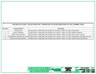
Sheet No. Component /Detail Description
Sheet No. Component /Detail Description
Sheet No. Component /Detail Description

You also want an ePaper? Increase the reach of your titles
YUMPU automatically turns print PDFs into web optimized ePapers that Google loves.
Galaxy 3500® 10K and 40K UPS Frame (1 Module) Site Planning Data<br />
Battery - <strong>No</strong>minal Voltage : +/-192V DC<br />
Input and output Voltage : 400V AC<br />
UPS<br />
Rating<br />
SKU Number<br />
EFFICIENCY DETAILS<br />
System Mains Input<br />
<strong>No</strong>minal<br />
Current(A)<br />
Maximum<br />
Current(A)<br />
SYSTEM 25% LOAD 50% LOAD 75% LOAD 100% LOAD<br />
10KVA 400V 92.9 94.8 94.9 94.9<br />
15KVA 400V 92.9 95.3 95.5 95.5<br />
20KVA 400V 94.4 95.5 95.5 95.4<br />
30KVA 400V 94.1 96 95.9 96.1<br />
40KVA 400V 95 96 95.9 95.5<br />
System<br />
Bypass<br />
Input<br />
<strong>No</strong>minal<br />
Current(A)<br />
System Output<br />
System<br />
output<br />
Power<br />
<strong>No</strong>minal<br />
Current(A)<br />
Batte ry<br />
Current(A)<br />
(in UPS<br />
Cabinet)<br />
Recommended Over current<br />
Protection Device Ratings<br />
UPS<br />
Mains<br />
Input (A)<br />
UPS<br />
Bypass<br />
Input (A)<br />
UPS<br />
System<br />
Output<br />
(A)<br />
Typical<br />
Dimensions<br />
H x W x D (mm)<br />
see note 14<br />
UPS Mechanical Data<br />
weight<br />
(Kg) see<br />
<strong>No</strong>te 14<br />
G35T10KH1B2S 1491x352x838 214 725<br />
G35T10KH2B2S 1491x352x838 306 1037<br />
10kVA/ G35T10KH1B4S 10kVA/<br />
1491x523x838 351 801<br />
12.3 13.5 14.4<br />
14.4 27.5 16 16 16<br />
440<br />
8kW G35T10KH2B4S 8kW<br />
1491x523x838 443 1011<br />
G35T10KH3B4S 1491x523x838 535 1221<br />
G35T10KH4B4S 1491x523x838 627 1431<br />
G35T15KH2B2S 1491x352x838 402 1363<br />
15kVA/ G35T15KH2B4S 15kVA/<br />
1491x523x838 443 1011<br />
18.5 20.3 21.7<br />
21.7 41.2 25 25 25<br />
516<br />
12kW G35T15KH3B4S 12kW<br />
1491x523x838 535 1221<br />
G35T15KH4B4S 1491x523x838 627 1431<br />
G35T20KH2B2S 1491x352x838 402 1363<br />
20kVA/ G35T20KH2B4S 20kVA/<br />
1491x523x838 443 1011<br />
24.7 27.2 28.9<br />
28.9 55 32 32 32<br />
751<br />
16kW<br />
G35T20KH3B4S 16kW<br />
1491x523x838 535 1221<br />
G35T20KH4B4S 1491x523x838 627 1431<br />
30kVA/ G35T30KH3B4S 30kVA/<br />
1491x523x838 570 1301<br />
36.7 40.3 43.3 43.3 82.5 50 50 50<br />
839<br />
24kW G35T30KH4B4S 24kW<br />
1491x523x838 662 1510<br />
40kVA/<br />
40kVA/<br />
G35T40KH4B4S 49.1 54 57.7<br />
57.7 110.1 63 63 63 1491x523x838 662 1510 1279<br />
32kW<br />
32kW<br />
<strong>No</strong>tes.<br />
1. <strong>No</strong>minal Input current based on nominal mains voltage + batteries fully charged at 100% ohmic load.<br />
2. Maximum Input current based on fully battery recharge + nominal mains voltage at 100% ohmic load.<br />
3. Suggested input overcurrent protection based on continuous full load.<br />
4. <strong>No</strong>minal battery voltage assumed to be 2.0 volts/ cell (lead technology)<br />
5. Over current protection device rating selection based on <strong>No</strong>minal input current is acceptable provided battery recharge time is short.<br />
Consult Schneider Electric for application specific assistance.<br />
6. Voltage tolerance is 304 - 477V, 47 - 53Hz for nominal 50Hz.<br />
7. Input power-factor is 0.98 for > 50% loading.<br />
8. Cable installation to comply with EN60364-5-52, max ambient 30 deg C, cable sizes shown<br />
refer to 600V rated,90 degree C multicore copper conductors with thermosetting insulation unless otherwise mentioned<br />
9. AC input & output to be L1, L2, L3, N & PE depending on 400/230V configuration, PE may be separate or SWA of armored cable<br />
10. Overcurrent protective devices (OCPD) may be either gL fuse type or MCB/MCCB rated at 30kA fault rating<br />
11. DC cabling should be sized to give < 1% voltage drop at the nominal battery discharge current<br />
using three-wire separate conductors in positive, centre-tap and negative poles<br />
12. Top or bottom cable entry with removable gland plates<br />
13. Control wiring to be run separately using screened conductors away from power cabling preferably in a separate conduit or cable tray<br />
14. Weights and dimensions are with internal batteries, with extended battery cabinets use battery discharge current<br />
in conjunction with cable drop to size cabling from cabinet to UPS<br />
15. Heat loss refers to max loading and fully charged batteries<br />
16. Refers to maximum battery recharge conditions<br />
17. Input: THD < 5% at Full Load<br />
18. Output:THD