Standardized DVB-T2 RF specifications - DigitalEurope
Standardized DVB-T2 RF specifications - DigitalEurope
Standardized DVB-T2 RF specifications - DigitalEurope

Create successful ePaper yourself
Turn your PDF publications into a flip-book with our unique Google optimized e-Paper software.
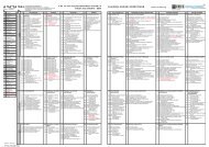
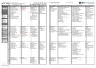
8- 4- Immunity to LTE signals in other channels<br />
Figure 1 shows the harmonized 800MHz spectrum organization for LTE deployment. There<br />
is only a small 1 MHz guard band between the top TV channel 60 and the lowest LTE base<br />
station in block A. Also the LTE handset (UE) block C falls on the N+9 image channel of TV<br />
tuner designs employing a 36MHz IF frequency. It is important to test immunity to these<br />
types of adjacent channel interference. Recent tests on existing DTT receivers have shown<br />
the most challenging form of interference for some receivers is when the LTE interferer is<br />
bursty – typical of a lightly loaded or idling LTE network. Signals captured from a real LTE<br />
base station (BS) and handset (UE) are used as interference sources to test that receivers<br />
provide a reasonable level of immunity against this type of bursty interference. The I/C<br />
specification set in Table 5 is designed to reject badly behaving receivers. These interference<br />
signals are in the following files available on the DIGITALEUROPE website:<br />
766-<br />
774<br />
MHz<br />
DTT<br />
CH58<br />
� Base Station: LTE_BS-idle_V2.wv (a lightly loaded 10MHz LTE BS signal consisting<br />
mainly of synchronisation and broadcast signals)<br />
� Handset : LTE_UE_1Mbs_V2.wv (a lightly loaded 10MHz LTE UE signal with 1Mbit/s<br />
data traffic)<br />
774-<br />
782<br />
MHz<br />
DTT<br />
CH59<br />
Figure 1– Harmonised 800MHz spectrum for LTE Deployment<br />
782-<br />
790<br />
MHz<br />
DTT<br />
CH60<br />
791-<br />
796<br />
MHz<br />
1 MHz<br />
Guard Band<br />
796-<br />
801<br />
MHz<br />
10 MHz BS<br />
Block A<br />
801-<br />
806<br />
MHz<br />
806-<br />
811<br />
MHz<br />
10 MHz BS<br />
Block B<br />
811-<br />
816<br />
MHz<br />
Downlink (BS)<br />
6 blocks of 5MHz or<br />
3 blocks of 10 MHz<br />
816-<br />
821<br />
MHz<br />
10 MHz BS<br />
Block C<br />
821-832<br />
MHz<br />
11 MHz<br />
Duplex Gap<br />
832-<br />
837<br />
MHz<br />
837-<br />
842<br />
MHz<br />
10 MHz UE<br />
Block A<br />
842-<br />
847<br />
MHz<br />
847-<br />
852<br />
MHz<br />
10 MHz UE<br />
Block B<br />
852-<br />
857<br />
MHz<br />
Uplink (UE)<br />
6 blocks of 5MHz or<br />
3 blocks of 10 MHz<br />
Table 5 – Immunity to LTE signals on other channels (I/C PFP1)<br />
Mode<br />
Note : Wanted signal centre at<br />
786 MHz<br />
BS-A<br />
(796<br />
MHz)<br />
BS-B<br />
(806<br />
MHz)<br />
UE-A<br />
(837<br />
MHz)<br />
UE-C<br />
(757<br />
MHz)<br />
857-<br />
862<br />
MHz<br />
10 MHz UE<br />
Block C<br />
Interferer power at tuner<br />
input(measured during<br />
active part of LTE signal) 6<br />
5 – 32KN 256Q 3/5 1/32 PP4 8MHz 30 dB 30 dB 30 dB 30 dB -15 dBm<br />
7 – 32KE 256Q 2/3 1/128 PP7 8MHz 30 dB 30 dB 30 dB 30 dB -15 dBm<br />
8 – 32KE 256Q 2/3 1/16 PP4 8MHz 30 dB 30 dB 30 dB 30 dB -15 dBm<br />
9 – 32KE 256Q 3/4 1/32 PP6 8MHz 30 dB 30 dB 30 dB 30 dB -15 dBm<br />
6 Note the power of the LTE BS and UE signal is defined as the RMS power during the active part of<br />
the signal. To assist setting the power level of the LTE BS_idle downlink signal, the RMS power<br />
measured by a power meter shall be set approximately 8.3 dB lower (e.g. -23.3dBm). Similarly for<br />
the LTE UE_1Mbs signal, the RMS power measured by a power meter shall be set approximately<br />
9.7 dB lower (e.g. -24.7 dBm).<br />
>>7 of 27