Standardized DVB-T2 RF specifications - DigitalEurope
Standardized DVB-T2 RF specifications - DigitalEurope
Standardized DVB-T2 RF specifications - DigitalEurope

Create successful ePaper yourself
Turn your PDF publications into a flip-book with our unique Google optimized e-Paper software.
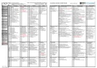
8- 2- Immunity to analogue signals in other channels<br />
The immunity for interference from analogue TV signals in adjacent and non-adjacent<br />
channels is specified as the maximum ratio of the interference to wanted signal (I/C) for<br />
reception (PFP1).<br />
Table 3 shows recommended I/C levels for different types of analogue TV interference.<br />
Table 3 – Immunity to analogue signals on other channels (I/C PFP1)<br />
Mode<br />
N±1<br />
PAL G<br />
PAL I1<br />
N±1<br />
PAL B 3<br />
N-1<br />
SECAM L<br />
PAL D1 4<br />
N+1<br />
SECAM L<br />
PAL D1 4<br />
N±m (m�1)<br />
andN+9 5<br />
SECAM L<br />
PAL D1 4<br />
N±m (m�1)<br />
and image<br />
channel 5<br />
PAL B/G/I1 5<br />
Bandwidth: 8 MHz 7 MHz 8 MHz 8 MHz 8 MHz 7/8 MHz<br />
5 – 32KN 256Q 3/5 1/32 PP4<br />
8MHz<br />
6 – 32KN 256Q 3/5 1/8 PP2<br />
7MHz<br />
7 – 32KE 256Q 2/3 1/128 PP7<br />
8MHz<br />
8 – 32KE 256Q 2/3 1/16 PP4<br />
8MHz<br />
9 – 32KE 256Q 3/4 1/32 PP6<br />
8MHz<br />
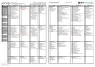
8- 3- Immunity to DTT signals in other channels<br />
36 28 30 43 44<br />
32 43<br />
35 27 29 42 43<br />
34 26 28 41 42<br />
33 25 27 40 41<br />
The immunity for interference from digital TV signals in adjacent and non-adjacent channels<br />
is specified as the maximum ratio of the interference to wanted signal (I/C) for reception<br />
(PFP1). Table 4 shows recommended I/C levels for <strong>DVB</strong>-T/<strong>T2</strong> interference.<br />
Note immunity to digital signals in other channels should use a <strong>DVB</strong>-T or non-extended <strong>DVB</strong>-<br />
<strong>T2</strong> interferer for the 7MHz mode and an extended <strong>DVB</strong>-<strong>T2</strong> mode interferer for 8MHz modes.<br />
Table 4 – Immunity to digital signals on other channels (I/C PFP1)<br />
Mode N±1 N±2 N±3<br />
N±m (m�1, m>3)<br />
except N+9 5<br />
5 – 32KN 256Q 3/5 1/32 PP4 8MHz 27 37 42 45 30<br />
6 – 32KN 256Q 3/5 1/8 PP2 7MHz 26 36 41 44 29<br />
7 – 32KE 256Q 2/3 1/128 PP7 8MHz 26 36 41 44 29<br />
8 – 32KE 256Q 2/3 1/16 PP4 8MHz 25 35 40 43 28<br />
9 – 32KE 256Q 3/4 1/32 PP6 8MHz 24 34 39 42 27<br />
3 Note that if PAL B N-1 is using NICAM sound, the digital channel on N cannot be used without an offset,<br />
because of the overlapping spectrums. The offset to be used in this test is recommended to be +167KHz on<br />
the wanted signal.<br />
4 Note that the figures for PAL D1 are provisional. Performance for PAL D/K is similar to D1.<br />
5 Note that N+9 is a popular choice for the image channel in tuner designs using 36MHz IF for 8MHz channel<br />
systems. For 7MHz systems, the image channel is N+10 (70MHz).<br />
N+9 5<br />
>>6 of 27