MAN 05MG02 installation • use • maintenance INSTRUCTIONS FOR ...
MAN 05MG02 installation • use • maintenance INSTRUCTIONS FOR ...
MAN 05MG02 installation • use • maintenance INSTRUCTIONS FOR ...

Create successful ePaper yourself
Turn your PDF publications into a flip-book with our unique Google optimized e-Paper software.
<strong>installation</strong> <strong>•</strong> <strong>use</strong> <strong>•</strong> <strong>maintenance</strong><br />
<strong>MAN</strong><br />
<strong>05MG02</strong><br />
<strong>INSTRUCTIONS</strong> <strong>FOR</strong> USE<br />
JIB CRANE<br />
“Column” <strong>•</strong> series GBA “Wall” <strong>•</strong> series GBP<br />
GBA<br />
GBP
<strong>INSTRUCTIONS</strong> <strong>FOR</strong> USE SERIES GBA – GBP JIB CRANE <strong>MAN</strong>05MGO2<br />
<strong>INSTRUCTIONS</strong><br />
<strong>FOR</strong> USE<br />
JIB CRANE<br />
“Column”<br />
series GBA<br />
“Wall”<br />
series GBP<br />
<strong>MAN</strong><strong>05MG02</strong>
<strong>MAN</strong>05MGO2 <strong>INSTRUCTIONS</strong> <strong>FOR</strong> USE SERIES GBA – GBP JIB CRANE<br />
INDEX<br />
1. PRELIMINARY IN<strong>FOR</strong>MATION 1<br />
1.1 Contents and <strong>use</strong> of the manual 1<br />
1.2 Symbols: meaning and <strong>use</strong> 1<br />
1.3 Co-operation with the <strong>use</strong>r 2<br />
1.4 Conformity with safety regulations 2<br />
1.5 The manufacturer’s responsibility and the warranty 3<br />
2. DESCRIPTION OF THE MACHINE AND TECHNICAL IN<strong>FOR</strong>MATION 4<br />
2.1 The manually rotated jib crane 4<br />
2.1.1 Intended <strong>use</strong> - Foreseen <strong>use</strong> - Designated <strong>use</strong> 4<br />
2.1.2 Constraints when installing 4<br />
2.1.3 The composition of the jib cranes 4<br />
2.2 Technical information and service conditions 7<br />
2.2.1 Safety reference list 7<br />
2.2.2 Protection and insulation of electrical parts 7<br />
2.2.3 Electrical power supply 7<br />
2.2.4 Environment conditions of <strong>use</strong> 7<br />
2.2.5 Noise - Vibrations 8<br />
2.2.6 Criteria of <strong>use</strong> and conditions of <strong>use</strong> 8<br />
2.2.7 Characteristics and technical data - Weights - Reactions on constraints 9<br />
3. SAFETY AND ACCIDENT PREVENTION 13<br />
3.1 Qualifications of qualified operators 13<br />
3.2 General safety regulations 14<br />
3.3 Safety symbols 14<br />
3.4 Warning about remaining risks 16<br />
3.5 Safety measures and instructions 17<br />
3.5.1 Control devices 17<br />
3.5.2 Safety and emergency devices 17<br />
3.5.3 Warning and signalling devices - List of labels 18<br />
4. HANDLING - INSTALLATION - PUTTING INTO OPERATION 19<br />
4.1 General notes at delivery 19<br />
4.2 Packing, transportation and handling 20<br />
4.2.1 Standard packing 20<br />
4.2.2 Transportation 20<br />
4.2.3 Handling 21<br />
4.2.4 Removing the packing and/or check of the crane parts 21<br />
4.3 Installation of the jib crane 22<br />
4.3.1 Duties and responsibilities of the installer 22<br />
4.3.2 Preparing the place of <strong>installation</strong> 23<br />
4.3.3 Assembly of the column – For GBA column-mounted cranes 24<br />
4.3.4 Assembly of the bracket – For GBP wall-mounted cranes 26<br />
4.3.5 Assembly of the arm – For GBA column-mounted cranes and GBP wall-mounted cranes 28<br />
4.3.6 Assembly of the electric system with the connector block 29<br />
4.3.6.1 Assembly of the electric system with isolating switch for GBA column-mounted cranes 59<br />
4.3.7 Assembly of the trolley/hoist 30<br />
4.4 Putting the machine into operation 31<br />
4.4.1 Preliminary operations – Adjustments and test runs 31<br />
4.4.2 Inspection of the jib crane – Suitability for <strong>use</strong> 32<br />
4.5 Out of service 34<br />
4.5.1 Storage and conservation of parts 34<br />
4.5.2 Re<strong>use</strong> after storage 34
<strong>INSTRUCTIONS</strong> <strong>FOR</strong> USE SERIES GBA – GBP JIB CRANE <strong>MAN</strong>05MGO2<br />
INDEX<br />
5. FUNCTIONING AND USE OF THE JIB CRANE 35<br />
5.1 Functions of the jib crane 35<br />
5.1.1 Intended <strong>use</strong> - Foreseen <strong>use</strong> - Designated <strong>use</strong> 35<br />
5.1.2 Permitted loads, loads not permitted 36<br />
5.1.3 Lifting accessories 36<br />
5.2 Operating conditions 37<br />
5.2.1 Operating environment 37<br />
5.2.2 Danger zones and people exposed to risk 37<br />
5.2.3 Illumination of the work area 38<br />
5.2.4 The operator 38<br />
5.2.5 The lifting capacity of the jib crane 38<br />
5.2.6 Manoeuvres: lifting, trolley traverse and arm rotation 39<br />
5.2.7 Safety devices 39<br />
5.3 Setting up - Starting the jib crane 40<br />
5.4 Switching off at the end of <strong>use</strong> 40<br />
5.5 Criteria and precautions of <strong>use</strong> 40<br />
5.6 Contraindications of <strong>use</strong> 42<br />
5.6.1 Use not intended and not allowed - Foreseeable and unforeseeable inappropriate <strong>use</strong> 42<br />
6. MAINTENANCE OF THE JIB CRANE 44<br />
6.1 Safety precautions 44<br />
6.2 The qualifications of <strong>maintenance</strong> staff 46<br />
6.3 Maintenance plan 49<br />
6.3.1 Daily and periodical <strong>maintenance</strong> 49<br />
6.3.2 Frequency and deadlines for <strong>maintenance</strong> work 50<br />
6.3.3 Check of efficiency of parts and components 51<br />
6.3.4 Cleaning and lubrication of the jib crane 54<br />
6.4 Adjusting and regulating 55<br />
6.4.1 Adjusting the rotation brake of the crane arm 55<br />
6.5 Breakdowns and solutions 56<br />
6.5.1 Main types of failure or breakdowns and possible solutions 56<br />
6.5.2 Authorised staff for intervention in case of breakdown 56<br />
6.5.3 Putting out of service 56<br />
6.6 Dismantling, disposal and scrapping 56<br />
7. SPARE PARTS 57<br />
8. THE CHECKS REGISTER 57<br />
9. WEIGHTS OF BRACKETS - ARMS - COLUMNS 58
<strong>MAN</strong>05MGO2 <strong>INSTRUCTIONS</strong> <strong>FOR</strong> USE SERIES GBA – GBP JIB CRANE<br />
Dear customer,<br />
LETTER ON DELIVERY<br />
<strong>•</strong> We thank you for having chosen a DONATI jib crane and we are happy to provide you with this technical<br />
publication which aims at achieving the maximum productivity of the machine in the safest way possible.<br />
<strong>•</strong> DONATI SOLLEVAMENTI S.r.l. produces jib cranes and relevant accessories, using a QUALITY SYSTEM in accordance<br />
with the UNI EN ISO 9001 regulations: 2000 certified by ICIM with N° 114.<br />
<strong>•</strong> This documentation, originally written in Italian, takes into consideration the EN 292 norm - 1° part point 3.20 and<br />
2° part point 5 and has been created in compliance with the requirements 1.7.4 and 4.4.2. of the Directive<br />
98/37CE ex 89/392CEE and successive amendments.<br />
<strong>•</strong> We would like you to read this manual carefully and to provide the staff who will work the jib crane with a copy of it.<br />
Example certification CISQ-ICIM<br />
Example certification IQ Net<br />
DONATI SOLLEVAMENTI S.r.l.
<strong>INSTRUCTIONS</strong> <strong>FOR</strong> USE SERIES GBA – GBP JIB CRANE <strong>MAN</strong>05MGO2<br />
1.1 Contents and <strong>use</strong> of the manual<br />
This technical publication, identified by the code <strong>MAN</strong><strong>05MG02</strong>, refers to “Jib cranes, manually rotated, in GBA<br />
series column-mounted model or GBP series wall-mounted model”, built and put on the market by the company:<br />
It refers to their “intended <strong>use</strong>”, to their technical functional and performance characteristics and to the relevant<br />
<strong>installation</strong>, <strong>use</strong> and <strong>maintenance</strong> instructions. It is intended for:<br />
<strong>•</strong> the supervisor of the factory, workshop, building site<br />
<strong>•</strong> the staff in charge of transporting, handling and <strong>installation</strong> of the equipment<br />
<strong>•</strong> the operators of the jib crane<br />
<strong>•</strong> the <strong>maintenance</strong> staff<br />
This manual must be kept by the person in charge of the above mentioned duties in a suitable place, so that it is<br />
always available for consultation and kept in the best possible state.<br />
If the manual is lost or becomes unusable, replacement documentation should be requested directly from the<br />
manufacturer by quoting the code of this manual.<br />
1.2 Symbols: meaning and <strong>use</strong><br />
1. - PRELIMINARY IN<strong>FOR</strong>MATION<br />
In this manual certain symbols are <strong>use</strong>d to focus the reader’s attention and underline some particularly important<br />
aspects of the subject.<br />
The following table shows the list and meaning of the symbols <strong>use</strong>d in the manual.<br />
Danger<br />
Warning<br />
Warning / Note<br />
Visual observation<br />
Action to be taken<br />
DONATI SOLLEVAMENTI S.r.l.<br />
Via Roma, 55 - 21020 Daverio (VA)<br />
Tel. 0332.942611 - Fax. 0332.948597<br />
The manufacturer retains the material and intellectual rights of this publication and forbids<br />
the divulgation and duplication, even partial, without prior written permission.<br />
Copyright © 2002 by DONATI SOLLEVAMENTI S.r.l.<br />
SYMBOL MEANING EXPLANATION, ADVICE, NOTES<br />
<strong>•</strong> Indicates a danger with risk of accident, possibly fatal.<br />
<strong>•</strong> Failure to follow the attached instructions can ca<strong>use</strong> a situation of serious danger for the<br />
safety of the operator and for people in the vicinity!<br />
<strong>•</strong> Follow the instructions scrupulously!<br />
<strong>•</strong> Represents a warning note of attention of possible deterioration of the jib or of a personal<br />
object of the operator.<br />
<strong>•</strong> Important warning which requires one’s utmost care.<br />
<strong>•</strong> Indicates a warning or a note about key functions or <strong>use</strong>ful information.<br />
<strong>•</strong> A printed eye can indicate to the reader that:<br />
a) He should proceed to a visual observation.<br />
b) He should proceed to the operating sequence.<br />
c) It is necessary to take a reading, to check a signal, etc.<br />
1
2<br />
<strong>MAN</strong>05MGO2 <strong>INSTRUCTIONS</strong> <strong>FOR</strong> USE SERIES GBA – GBP JIB CRANE<br />
1.3 Co-operation with the <strong>use</strong>r<br />
This manual reflects the configuration of the machine at the time the machine was put on the market.<br />
Any change to the manual, a copy of which will be sent to the customer by the manufacturer, shall be kept together<br />
with the manual.<br />
The manufacturer is willing to supply its customers with any additional information they may require, and welcomes<br />
any suggestions aimed at improving the manual so that it corresponds better to the customer’s needs.<br />
If the jib crane is no longer to be <strong>use</strong>d the main <strong>use</strong>r is invited to deliver, with the hoist, this manual and the relevant<br />
documentation enclosed with it (declarations, schemes, control register etc.).<br />
1.4 Conformity with safety regulations<br />
The jib crane was designed and produced following the “Essential Safety Requirements” of Enclosure I of the<br />
Community Directive 98/37/EC ex 89/392/EEC and successive amendments 91/368/EEC, 93/44/EEC and<br />
93/68/EEC, denominated Machines Directive, transposed into Italian legislation with DPR N° 459 of 24.07.96.<br />
Regarding what was stated in Enclosure II of the Directive 98/37/CE, the crane can be put on the market in the<br />
following ways:<br />
A) Complete, or capable of functioning independently, having the CE Mark and the EC Declaration of<br />
Conformity - Enclosure II A.<br />
B) Incomplete as destined to be incorporated in another machine and/or to be completed (i.e.: hoist) by<br />
the Customer.<br />
In this case, in accordance with Article 4 - paragraph 2 of the Directive 98/37/CE, the jib crane<br />
does not carry the CE Mark and is supplied with the Declaration of the Manufacturer - Enclosure II B.<br />
example CE Declaration CE of Conformity<br />
Enclosure II A<br />
example Declaration by the Manufacturer<br />
Enclosure II B
<strong>INSTRUCTIONS</strong> <strong>FOR</strong> USE SERIES GBA – GBP JIB CRANE <strong>MAN</strong>05MGO2<br />
1.5 The manufacturer’s responsibility and the warranty<br />
With reference to the contents of this manual DONATI SOLLEVAMENTI S.r.l. declines any responsibility in case of:<br />
<strong>•</strong> <strong>use</strong> of the jib crane contrary to the national safety and accident prevention laws<br />
<strong>•</strong> erroneous choice of the building site or buildings in which the jib crane is to be operated<br />
<strong>•</strong> voltage and power supply faults<br />
<strong>•</strong> lack of or erroneous observation of the instructions supplied in this manual<br />
<strong>•</strong> non-authorised modifications to the machine<br />
<strong>•</strong> <strong>use</strong> (of the machine) by untrained or unsuitable staff<br />
To be able to <strong>use</strong> the warranty, the certification of which is shown below, the Customer must scrupulously follow<br />
the instructions indicated in this manual, and in particular:<br />
<strong>•</strong> always work within the <strong>use</strong> limits of the jib crane<br />
<strong>•</strong> always carry out constant, diligent <strong>maintenance</strong><br />
<strong>•</strong> appoint operators of proven capability, who have been adequately trained for the job to <strong>use</strong> the machine<br />
<strong>•</strong> <strong>use</strong> solely original spare parts indicated by the manufacturer<br />
<strong>•</strong> The intended <strong>use</strong> and configurations of the hoist are the only ones allowed.<br />
Do not try to <strong>use</strong> the hoist disregarding the supplied instructions.<br />
<strong>•</strong> The instructions in this manual do not replace but add to the obligations regarding the current<br />
legislation for accident prevention standards.<br />
CERTIFICATE OF WARRANTY<br />
<strong>•</strong> DONATI SOLLEVAMENTI S.r.l. is the “Manufacturer” of the column-mounted jib crane of the series GBA and<br />
wall-mounted jib crane of the series GBP, the subject of this technical publication.<br />
<strong>•</strong> DONATI SOLLEVAMENTI S.r.l. carries out the check on manufacturing regarding the “Quality<br />
system” of the company by ICIM with N° 114, according to the standard UNI EN ISO 9001: 2000.<br />
All jib cranes, series GBA and GBP, are covered by the following warranty formula:<br />
1. The warranty of the machine lasts for 36 months from delivery, attested to by the date of the invoice, taking into account the<br />
specifications and exclusions outlined as will follow and except for different explicit agreements between the parties. It is subject to the<br />
reporting by registered letter, within 8 days of the discovery of faults and the recognition of the existence of these by DONATI<br />
SOLLEVAMENTI S.r.l.<br />
2. The warranty covers exclusively the resulting faulty parts from ca<strong>use</strong>s attributable to DONATI SOLLEVAMENTI S.r.l. and includes the<br />
replacement or repair of the faulty part excluding the dismantling, reassembly and despatch costs. The parts which DONATI<br />
SOLLEVAMENTI S.r.l. recognizes as faulty will have free despatch from the factory situated in Daverio (VA).<br />
3. For components provided by third parties (commercial, electrical, mechanical and electromechanical components) the prevailing<br />
warranty conditions are those of the respective manufacturers.<br />
4. Parts damaged during transportation or handling, as well as those subject to normal wear and tear (e.g. gaskets) and/or to perishing by<br />
atmospheric or environmental agents are excluded from the warranty. Damage from lack of or insufficient or wrong <strong>maintenance</strong>, from<br />
unskilful <strong>use</strong>, improper <strong>use</strong>, <strong>use</strong> not allowed or not intended, from non-authorised modifications or repairs, from tampering and from<br />
interventions by unqualified staff or not as explained in the manufacturer’s instructions are excluded from the warranty.<br />
5. The validity of the warranty is subject to the correct <strong>installation</strong>, periodical checks and <strong>maintenance</strong> as in the instruction manual for<br />
“<strong>installation</strong>, <strong>use</strong> and <strong>maintenance</strong>”, which accompanies the machine, as well as the diligent annotations in the enclosed “control<br />
register” of all the <strong>maintenance</strong> work, checks, verifications, and periodical inspections.<br />
6. The replacement of faulty parts does not imply the renewal of the period of warranty of the whole machine. DONATI SOLLEVAMENTI<br />
S.r.l. is in any case exonerated from any obligation to give compensation to any claim and the Purchaser renounces any claim for costs<br />
or damages, direct or indirect, also to third parties, due to any standstill.<br />
7. The warranty is lost if non-original DONATI spare parts or spare parts not prescribed by DONATI are <strong>use</strong>d.<br />
8. For any dispute the Foro Giudiziario (Law Courts) of Varese is exclusively competent.<br />
DONATI SOLLEVAMENTI S.r.l.<br />
3
4<br />
<strong>MAN</strong>05MGO2 <strong>INSTRUCTIONS</strong> <strong>FOR</strong> USE SERIES GBA – GBP JIB CRANE<br />
2. - DESCRIPTION OF THE MACHINE AND TECHNICAL IN<strong>FOR</strong>MATION<br />
2.1 The manually rotated jib crane<br />
2.1.1 Intended <strong>use</strong> - Foreseen <strong>use</strong> - Designated <strong>use</strong><br />
The jib cranes, manually rotated,in GBA series column-mounted model or GBP series wall-mounted model, are<br />
produced to move goods within the plant.<br />
The jib cranes have three functions:<br />
<strong>•</strong> lifting a load vertically, by means of the hook of the lifting block, generally made of a manual or electric chain hoist<br />
and using the appropriate accessories for such an operation;<br />
<strong>•</strong> moving a load with the aid of an electric or manual trolley which runs along the radial axis of the crane jib;<br />
<strong>•</strong> rotating a load, around the constraint axis of the jib, by manually pushing the load, in the circular area below,<br />
delineated by the rotation radius of the jib.<br />
2.1.2 Constraints when installing<br />
The GBA column-mounted jib cranes are intended to be fixed to the ground, the column is self-supporting and<br />
can be fixed to the ground using log bolts, on a foundation plinth or in special cases having checked suitability, also<br />
with screw anchors or dowelling.<br />
The GBP wall-mounted jib cranes are intended to be fixed to an existing structure (columns, walls, machine<br />
casing,etc), using a system of brackets and staybolts, either with fixing screws or, subject to a check, with screw<br />
anchors or dowelling.<br />
In both cases (column-mounted and wall-mounted cranes) the <strong>use</strong>r MUST check, directly or using<br />
specialised staff, the suitability of the surfaces to be fixed on. These surfaces must guarantee the<br />
stability and safety of the crane in all its working conditions, supporting the lifting operations and the<br />
dynamic effects of the tilting momentum and of the type and speed of lifting.<br />
2.1.3 The composition of the jib cranes<br />
The composition of the jib crane is relatively simple, both in the column-mounted version and the wall-mounted one.<br />
Both have a steel structure, the lifting block made up of a chain hoist (electric or manual), the translation unit formed<br />
by a hoist-carrying trolley (electric or push-trolley), a series of accessories ( support brackets, staybolts, foundation<br />
plinth,electric unit, etc.).<br />
The GBA column-mounted jib crane consists of a tubular column with polygonal section fixed using log bolts or<br />
bolts at the base of appropriate size and an arm which rotates round the axis of the column itself.<br />
The GBP wall-mounted jib crane consists of a bracket support structure which is bolted on the support structure<br />
(fixed to the wall or anchored to a column) and an arm which rotates around an axis on the support bracket.<br />
Both versions are equipped, in most cases, with a chain hoist, fitted with a trolley.
<strong>INSTRUCTIONS</strong> <strong>FOR</strong> USE SERIES GBA – GBP JIB CRANE <strong>MAN</strong>05MGO2<br />
Column (GBA column-mounted version):<br />
Made of pressed steel bent in a tubular structure with a polygonal shape it allows a high rigidity and stability for the<br />
crane; it is fixed to the base using a base plate and a system of bolts or log bolts. In the upper part a couple of plates<br />
support the arm of the crane and allow it to rotate (fig.1).<br />
Support bracket ( GBP wall-mounted version):<br />
It is formed of a couple of plates made of pressed steel; fixed to the wall or anchored to a column using staybolts or<br />
screws, it acts as a support to the arm and allows it to rotate (fig. 2).<br />
The rotating arm:<br />
The arm, rotating around its own axis on grazing ball bearings, is formed by a support girder for the sliding of the<br />
hoist-carrying trolley and comes in three basic models for loads from 125 to 2000kg and ranges up to 8m. (fig.3):<br />
<strong>•</strong> The arm in the channel model: Made with the <strong>use</strong> of a special section bar made of formed steel inside which the<br />
hoist-carrying trolley slides. The arm is fitted with one or two staybolts which support the shape and link it to the<br />
rising rotating tube. This model features extreme lightness of movement due to the low inertia from its own reduced<br />
weight. This model of the crane is normally supplied with a push trolley.<br />
<strong>•</strong> The arm in the staybolted girder model: Made using a double-T formed steel beam girder the lower flange of<br />
which the hoist-carrying trolley slides on. The arm is fitted with one or two staybolts for the support of the beam<br />
which connects it to the rising rotating tube. The crane can be <strong>use</strong>d with push trolleys, electric trolleys or<br />
mechanical ones.<br />
<strong>•</strong> The arm in the cantilever model: Made using a double-T formed steel beam girder the lower flange of which the<br />
hoist-carrying trolley slides on. The girder is a self-supporting cantilever, without support staybolts, and it is directly<br />
solid, using suitable reinforcement, to the rising rotating tube. It allows an optimal <strong>use</strong> of the available space at a<br />
height, due to the absence of staybolts. The crane can be <strong>use</strong>d with push-trolleys, electric trolleys or mechanical<br />
ones.<br />
fig.1 fig.2<br />
fig.3<br />
5
6<br />
<strong>MAN</strong>05MGO2 <strong>INSTRUCTIONS</strong> <strong>FOR</strong> USE SERIES GBA – GBP JIB CRANE<br />
The braking device of the arm:<br />
It is made up of a clutch system with asbestos-free material, which allows the regulating of the rotating strain of the<br />
arm and ensures its positioning stability (fig. 4).<br />
The electrical system:<br />
It is intended for the electrical input of the hoist and/or trolley (if electric) which slides along the arm of the crane<br />
(fig. 5). It has a connector block, situated on the top of the column-mounted jib crane or on the arm support of the<br />
wall-mounted jib crane, for the connector between the line and the festooned cable.<br />
The distribution of energy <strong>use</strong>s festoon-cable which does not spread flames, generally of the flat type, sliding on<br />
suitable coasters or sleds that slide the whole way along the arm, inserted in the arm or in a special channel.<br />
Foundation frame with log bolts:<br />
This is supplied on request in the column-mounted version, for the fixing of the column itself to the base (foundation<br />
plinth). (fig. 6).<br />
Brackets and staybolts unit:<br />
Used for fixing to a pillar in the wall-mounted version, it is available on request. It is fitted with a system of pressure<br />
screws to guarantee the best adherence of the staybolts to the pillar (fig. 7).<br />
Finish:<br />
The protection of the steel structures from atmospheric and environmental agents (powders, gas, etc.) is guaranteed<br />
by the treatments which <strong>use</strong> yellow enamel paint, subject to preparation of the surfaces with metallic sanding of SA<br />
grade.<br />
Lifting and translation unit:<br />
The manually-rotated jib cranes in the column-mounted or wall-mounted version can be equipped with a chain hoist<br />
with the relevant trolley either in electric or manual version.<br />
For the measurements, weights and maximum admissible reactions on the wheels of the trolleys see the related table<br />
in paragraph “Technical data” 2.2<br />
fig.4 fig.5<br />
fig.6 fig.7
<strong>INSTRUCTIONS</strong> <strong>FOR</strong> USE SERIES GBA – GBP JIB CRANE <strong>MAN</strong>05MGO2<br />
The conception and construction:<br />
<strong>•</strong> The manually rotated jib cranes in the GBA column-mounted version and the GBP wall-mounted version are<br />
designed according to the conception of the modular components which put together in relation to commercial<br />
needs, as well as the standard models always available from the wareho<strong>use</strong>, allow the rapid economical realisation<br />
of numerous normalised and special executions.<br />
<strong>•</strong> The base, column, bracket and arms components, thanks to their extreme compactness are assemblable together,<br />
so as to guarantee the maximum <strong>use</strong> of the hook run and, thanks to the minimal side clearance allow an optimal<br />
<strong>use</strong> of the area in which the jib crane operates.<br />
<strong>•</strong> The construction <strong>use</strong>s the most advanced technology which is based on production processes of high<br />
industrialization and allows the realization, using economies of scale, of totally reliable and technically innovative<br />
machines. The high level of quality is guaranteed and controlled by the company quality system according to the<br />
UNI EN ISO 9001:2000 standard.<br />
2.2 Technical information and service conditions<br />
2.2.1 Safety reference list<br />
In the planning and construction of the manually rotated jib cranes, column-mounted series GBA and wall-mounted<br />
series GBP the following standards and principal technical regulations have been taken into account:<br />
<strong>•</strong> EN - 292 parts: 1 a - 2 a "Safety of machines".<br />
<strong>•</strong> EN - 60204 - 1 "Safety of electrical equipment of machines- General rules".<br />
<strong>•</strong> EN - 60204 - 32 "Safety of electrical equipment of lifting machines".<br />
<strong>•</strong> EN - 60529 “Degrees of IP protection”<br />
<strong>•</strong> ISO 4301 "Classification of lifting apparatus"<br />
<strong>•</strong> UNI 7670 "Calculation of the mechanisms of lifting apparatus"<br />
<strong>•</strong> FEM 1.001/98 “Calculation of lifting apparatus”<br />
<strong>•</strong> FEM 9.511/86 “Classification of mechanisms”<br />
<strong>•</strong> FEM 9.755/93 "Periods of safe work"<br />
2.2.2 Protection and insulation of electrical parts<br />
<strong>•</strong> Cables: CEI 20/22 II - Maximum insulation voltage 450/750 V<br />
2.2.3 Electrical power supply<br />
<strong>•</strong> The jib cranes are designed to be powered with alternating electric current with maximum three-phase<br />
voltage of 600 V<br />
2.2.4 Environment conditions of <strong>use</strong><br />
<strong>•</strong> Temperature of <strong>use</strong>: minimum –10° C; maximum +40° C<br />
<strong>•</strong> Maximum relative humidity: 80%<br />
<strong>•</strong> The machine must be placed in a well-ventilated place, free from corrosive vapours (acid vapours, saline<br />
clouds, etc)<br />
<strong>•</strong> It is forbidden to <strong>use</strong> the machine in an explosive environment or one which is potentially so, or where<br />
the <strong>use</strong> of flameproof equipment is prescribed.<br />
<strong>•</strong> It is necessary to allocate sufficient working space to ensure the safety of the operator and of the<br />
<strong>maintenance</strong> staff.<br />
7
8<br />
<strong>MAN</strong>05MGO2 <strong>INSTRUCTIONS</strong> <strong>FOR</strong> USE SERIES GBA – GBP JIB CRANE<br />
2.2.5 Noise - Vibrations<br />
<strong>•</strong> The jib cranes, being manually rotated, do not create noise during the movement of the flexing of the arm.<br />
<strong>•</strong> The vibrations produced by the jib crane, during the manual rotation of the arm, are practically nil and in any case<br />
not dangerous for the health of the staff who operate them.<br />
<strong>•</strong> Excessive noise or vibration can be ca<strong>use</strong>d by a fault which must be immediately notified and eliminated so as not<br />
to compromise the reliability of the jib crane.<br />
2.2.6 Criteria of <strong>use</strong> and conditions of <strong>use</strong><br />
The necessary indispensable conditions to obtain the full functional responsiveness of the jib crane for the service it<br />
is intended, as well as its optimal and lasting functioning, are in the correct choice of the model of machine. This<br />
choice must be made in relation to the real service performance required as well as the environmental conditions in<br />
which the jib crane will have to operate.<br />
The parameters which must be carefully considered in the choice of jib crane are:<br />
<strong>•</strong> The lifting capacity: this must be determined by the weight of the maximum load to be lifted and must never be<br />
less than this weight.<br />
<strong>•</strong> The functional dimensions: the height of the sliding girder of the trolley which determines the hook run of the<br />
hoist and the range must be selected so as to guarantee the functional coverage of the space to be <strong>use</strong>d<br />
considering the surrounding clearance.<br />
<strong>•</strong> The type of translation: manual or electric in relation to the characteristics of the mass to be moved and the type<br />
of arm already selected (channel-cantilever- staybolted girder).<br />
<strong>•</strong> The nature of the load: the nature of the load determines for its positioning the choice of the speeds of movement<br />
(lifting and translating) suited to the task. In some cases it is indispensable to <strong>use</strong> two-speed hoists with a slow<br />
positioning speed.<br />
<strong>•</strong> The area to be <strong>use</strong>d in: the jib crane features in its conception intrinsic high elasticity which becomes even more<br />
evident when it is <strong>use</strong>d for moving loads close to the maximum load and/or with prevalent localisation in the ends<br />
of the arm.<br />
<strong>•</strong> The environment to be <strong>use</strong>d in: the jib cranes are intended for service indoors and/or in a covered area, sheltered<br />
from bad weather and away from wind. In the case of <strong>use</strong> outdoors adequate steps must be taken in relation to<br />
the surface treatment (sanding, varnishing) as well as a system of stopping brake.<br />
<strong>•</strong> The frequency of <strong>use</strong>: if the <strong>use</strong> is very intense (frequent manoeuvres and/or repeated ones) with loads close to<br />
the maximum lifting capacity, the consequent fatigue of the operator due to the manual movements must be taken<br />
into account.<br />
<strong>•</strong> The correct evaluation of the parameters indicated above, in the case of the parameters being close<br />
to the upper limits, can lead to the need to <strong>use</strong> a crane with higher performance features which, once<br />
gone beyond, can guarantee more rigidity and fewer translating and rotating strains.<br />
<strong>•</strong> Using an electric trolley instead of a push-trolley can reduce the fatigue of the operator considerably.
<strong>INSTRUCTIONS</strong> <strong>FOR</strong> USE SERIES GBA – GBP JIB CRANE <strong>MAN</strong>05MGO2<br />
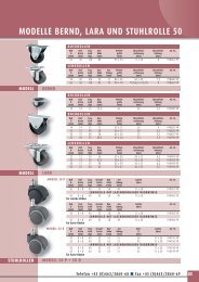
2.2.7 Characteristics and technical data - Weights - Reactions on constraints<br />
C Version - channel profile version<br />
Lifting<br />
capacity<br />
63<br />
125<br />
250<br />
500<br />
1000<br />
Wall-mounted jib crane – Rotation 270°<br />
Dimensions M* and N* for wall-mounted jib cranes: See corresponding heights relative to column-mounted jib cranes<br />
Arm<br />
Nominal<br />
True Lenght<br />
S<br />
Size of jib crane<br />
kg m mm A<br />
4 4056 A<br />
5 5056 A<br />
6 6056 B<br />
7 7056 B<br />
2 2056 A<br />
3 3056 A<br />
4 4056 B<br />
5 5056 B<br />
6 6066 C<br />
7 7066 C<br />
2 2056 B<br />
3 3056 B<br />
4 4066 C<br />
5 5066 C<br />
6 6066 D<br />
7 7066 D<br />
2 2066 C<br />
3 3066 C<br />
4 4066 D<br />
5 5066 D<br />
6 6076 E<br />
7 7076 E<br />
2 2066 D<br />
3 3066 D<br />
4 4076 E<br />
5 5076 E<br />
6 6076 F<br />
7 7076 F<br />
GBP series wall-mounted jib cranes - C version<br />
Type Overrall dimensions (mm)<br />
weight of crane<br />
B C D E F Ø kg<br />
C01A40 170 552 644 200 594 150 15 74<br />
C01A50 170 552 644 200 594 150 15 87<br />
C01B60 170 552 644 200 594 150 15 100<br />
C01B70 170 552 644 200 594 150 15 113<br />
C01A20 170 552 644 200 594 150 15 48<br />
C01A30 170 552 644 200 594 150 15 61<br />
C01B40 170 552 644 200 594 150 15 74<br />
C01B50 170 552 644 200 594 150 15 87<br />
C02C60 210 820 930 250 870 190 22 135<br />
C02C70 210 820 930 250 870 190 22 150<br />
C01B20 170 552 644 200 594 150 15 48<br />
C01B30 170 552 644 200 594 150 15 61<br />
C02C40 210 820 930 250 870 190 22 105<br />
C02C50 210 820 930 250 870 190 22 120<br />
C02D60 210 820 930 250 870 190 22 202<br />
C02D70 210 820 930 250 870 190 22 228<br />
C02C20 210 820 930 250 870 190 22 75<br />
C02C30 210 820 930 250 870 190 22 90<br />
C02D40 210 820 930 250 870 190 22 113<br />
C02D50 210 820 930 250 870 190 22 129<br />
C03E60 255 1100 1240 300 1160 220 34 270<br />
C03E70 255 1100 1240 300 1160 220 34 300<br />
C02D20 210 820 930 250 870 190 22 93<br />
C02D30 210 820 930 250 870 190 22 163<br />
C03E40 255 1100 1240 300 1160 220 34 212<br />
C03E50 255 1100 1240 300 1160 220 34 241<br />
C03F60 255 1100 1240 300 1160 220 34 298<br />
C03F70 255 1100 1240 300 1160 220 34 331<br />
Column-mounted jib crane – Rotation 300°<br />
GBA series column-mounted jib crane – C version<br />
Total Height<br />
H<br />
m<br />
Type<br />
Under<br />
beam<br />
Overrall dimensions (mm)<br />
3 C30A40 2496 220 34 125 585 12 124 18<br />
3 C30A50 2496 220 34 125 645 12 137 18<br />
3 C30B60 2496 255 34 125 730 12 182 28<br />
3 C30B70 2496 255 34 125 790 12 195 28<br />
3 C30A20 2496 220 34 125 525 12 98 18<br />
3 C30A30 2496 220 34 125 585 12 111 18<br />
3 C30B40 2496 255 34 125 610 12 156 28<br />
3 C30B50 2496 255 34 125 670 12 169 28<br />
3.5 C35C60 2738 310 34 125 800 17 253 34<br />
3.5 C35C70 2738 310 34 125 860 17 268 34<br />
3 C30B20 2496 255 34 125 550 12 130 28<br />
3 C30B30 2496 255 34 125 610 12 143 28<br />
3.5 C35C40 2738 310 34 125 680 17 223 34<br />
3.5 C35C50 2738 310 34 125 740 17 238 34<br />
3.5 C35D60 2738 360 40 140 850 17 381 51<br />
3.5 C35D70 2738 360 40 140 910 17 407 51<br />
3.5 C35C20 2738 310 34 250 745 17 193 34<br />
3.5 C35C30 2738 310 34 250 805 17 208 34<br />
3.5 C35D40 2738 360 34 250 850 17 292 51<br />
3.5 C35D50 2738 360 34 250 910 17 308 51<br />
4 C40E60 2980 415 40 140 860 20 576 73<br />
4 C40E70 2980 415 40 140 920 20 606 73<br />
3.5 C35D20 2738 360 50 300 830 17 272 51<br />
3.5 C35D30 2738 360 50 300 890 17 342 51<br />
4 C40E40 2980 415 50 300 900 20 518 73<br />
4 C40E50 2980 415 50 300 960 20 547 73<br />
4 C40F60 2980 480 50 300 1140 20 721 100<br />
4 C40F70 2980 480 50 300 1200 20 754 100<br />
9<br />
Weight<br />
Crane<br />
Column by m<br />
G L M N Δ kg kg
10<br />
<strong>MAN</strong>05MGO2 <strong>INSTRUCTIONS</strong> <strong>FOR</strong> USE SERIES GBA – GBP JIB CRANE<br />
T Version - cantilever version<br />
Lifting<br />
capacity<br />
63<br />
125<br />
250<br />
500<br />
1000<br />
2000<br />
Wall-mounted jib crane - Rotation 250°<br />
Dimensions M* and N* for wall-mounted jib cranes: see corresponding heights relative to column-mounted jib cranes<br />
Arm<br />
Size of jib crane<br />
S<br />
kg m mm<br />
4 A<br />
5 A<br />
2 A<br />
3 A<br />
4 B<br />
5 B<br />
2 B<br />
3 B<br />
4 C<br />
5 C<br />
2 C<br />
3 C<br />
4 D<br />
5 D<br />
2 D<br />
3 D<br />
4 E<br />
5 E<br />
2 E<br />
3 E<br />
GBP series wall-mounted jib cranes – T version<br />
Type Overall dimensions (mm)<br />
A<br />
Weight of crane<br />
B C D E F Ø kg<br />
T01A40 170 248 644 200 594 150 15 95<br />
T01A50 170 248 644 200 594 150 15 111<br />
T01A20 170 248 644 200 594 150 15 63<br />
T01A30 170 248 644 200 594 150 15 79<br />
T01B40 170 288 644 200 594 150 15 125<br />
T01B50 170 288 644 200 594 150 15 147<br />
T01B20 170 288 644 200 594 150 15 81<br />
T01B30 170 288 644 200 594 150 15 103<br />
T02C40 210 346 930 250 870 190 22 195<br />
T02C50 210 346 930 250 870 190 22 226<br />
T02C20 210 346 930 250 870 190 22 134<br />
T02C30 210 346 930 250 870 190 22 165<br />
T02D40 210 406 930 250 870 190 22 256<br />
T02D50 210 406 930 250 870 190 22 298<br />
T02D20 210 406 930 250 870 190 22 172<br />
T02D30 210 406 930 250 870 190 22 214<br />
T03E40 255 499 1240 300 1160 220 34 381<br />
T03E50 255 499 1240 300 1160 220 34 438<br />
T03E20 255 499 1240 300 1160 220 34 267<br />
T03E30 255 499 1240 300 1160 220 34 324<br />
Column-mounted jib crane - Rotation 290°<br />
GBA series column-mounted jib cranes – T version<br />
Total height<br />
H<br />
m<br />
Type<br />
Under<br />
beam<br />
Overall dimensions<br />
h G M N<br />
Weight<br />
3 T30A40 2800 220 180 640 160 12 145 18<br />
3 T30A50 2800 220 180 700 160 12 161 18<br />
3 T30A20 2800 220 180 580 160 12 113 18<br />
3 T30A30 2800 220 180 640 160 12 129 18<br />
3 T30B40 2760 255 180 680 200 12 207 28<br />
3 T30B50 2760 255 180 740 200 12 229 28<br />
3 T30B20 2760 255 180 620 200 12 163 28<br />
3 T30B30 2760 255 180 680 200 12 185 28<br />
3.5 T35C40 3212 310 180 740 240 17 313 34<br />
3.5 T35C50 3212 310 180 800 240 17 344 34<br />
3.5 T35C20 3212 310 180 680 240 17 252 34<br />
3.5 T35C30 3212 310 180 740 240 17 283 34<br />
3.5 T35D40 3152 360 180 800 300 17 435 51<br />
3.5 T35D50 3152 360 180 860 300 17 477 51<br />
3.5 T35D20 3152 360 180 740 300 17 351 51<br />
3.5 T35D30 3152 360 180 800 300 17 393 51<br />
4 T40E40 3581 415 180 870 360 20 687 73<br />
4 T40E50 3581 415 180 930 360 20 744 73<br />
4 T40E20 3581 415 220 850 360 20 573 73<br />
4 T40E30 3581 415 220 910 360 20 630 73<br />
Crane<br />
Column by m<br />
T<br />
(IPE) Δ kg kg
H Version - Overbraced version<br />
Lifting<br />
capacity<br />
125<br />
250<br />
500<br />
1000<br />
2000<br />
<strong>INSTRUCTIONS</strong> <strong>FOR</strong> USE SERIES GBA – GBP JIB CRANE <strong>MAN</strong>05MGO2<br />
Wall-mounted jib crane – Rotation 270°<br />
Dimensions M* and N* for wall-mounted jib cranes: see corresponding heights relative to column-mounted jib cranes<br />
Arm<br />
Size of jib crane<br />
S<br />
kg m mm<br />
6 C<br />
7 C<br />
8 D<br />
4 C<br />
5 C<br />
6 D<br />
7 D<br />
8 E<br />
4 D<br />
5 D<br />
6 E<br />
7 E<br />
8 F<br />
4 E<br />
5 E<br />
6 F<br />
7 F<br />
4 E<br />
5 E<br />
GBP series wall-mounted jib crane – H version<br />
Type Overall dimensions (mm)<br />
A<br />
Weight of crane<br />
B C D E F Ø kg<br />
H02C60 210 820 930 250 870 190 22 160<br />
H02C70 210 820 930 250 870 190 22 180<br />
H02D80 210 820 930 250 870 190 22 251<br />
H02C40 210 820 930 250 870 190 22 122<br />
H02C50 210 820 930 250 870 190 22 141<br />
H02D60 210 820 930 250 870 190 22 200<br />
H02D70 210 820 930 250 870 190 22 226<br />
H03E80 255 1100 1240 300 1160 220 34 303<br />
H02D40 210 820 930 250 870 190 22 149<br />
H02D50 210 820 930 250 870 190 22 175<br />
H03E60 255 1100 1240 300 1160 220 34 262<br />
H03E70 255 1100 1240 300 1160 220 34 293<br />
H03F80 255 1100 1240 300 1160 220 34 389<br />
H03E40 255 1100 1240 300 1160 220 34 200<br />
H03E50 255 1100 1240 300 1160 220 34 231<br />
H03F60 255 1100 1240 300 1160 220 34 312<br />
H03F70 255 1100 1240 300 1160 220 34 351<br />
H03F40 255 1100 1240 300 1160 220 34 233<br />
H03F50 255 1100 1240 300 1160 220 34 272<br />
Column-mounted jib crane – Rotation 300°<br />
GBA series column-mounted jib crane - H version<br />
Total Height<br />
H<br />
m<br />
Type<br />
Under<br />
beam<br />
11<br />
Overall dimensions (mm) Weight<br />
h G M N<br />
3.5 H35C60 2738 310 180 890 160 17 278 34<br />
3.5 H35C70 2738 310 180 950 160 17 298 34<br />
3.5 H35D80 2738 310 180 1070 200 17 430 51<br />
3.5 H35C40 2738 310 180 770 160 17 240 34<br />
3.5 H35C50 2738 310 180 830 160 17 259 34<br />
3.5 H35D60 2738 360 180 950 200 17 379 51<br />
3.5 H35D70 2738 360 180 1010 200 17 405 51<br />
4 H40E80 2980 360 180 1140 200 20 629 73<br />
3.5 H35D40 2738 360 180 830 200 17 328 51<br />
3.5 H35D50 2738 360 180 890 200 17 354 51<br />
4 H40E60 2980 415 180 1020 200 20 568 73<br />
4 H40E70 2980 415 180 1080 200 20 599 73<br />
4 H40F80 2980 415 180 1220 240 20 812 100<br />
4 H40E40 2980 415 180 900 200 20 506 73<br />
4 H40E50 2980 415 180 960 200 20 537 73<br />
4 H40F60 2980 480 180 1100 240 20 735 100<br />
4 H40F70 2980 480 180 1160 240 20 774 100<br />
4 H40F40 2980 480 220 1020 240 20 656 100<br />
4 H40F50 2980 480 220 1080 240 20 695 100<br />
Crane<br />
Column by m<br />
T<br />
(IPE) Δ kg kg
12<br />
<strong>MAN</strong>05MGO2 <strong>INSTRUCTIONS</strong> <strong>FOR</strong> USE SERIES GBA – GBP JIB CRANE<br />
Fixing systems for jib cranes<br />
Bracket and staybolt unit for GBP wall-mounted cranes<br />
Size of crane A B C D E F<br />
Reactions<br />
(kN)<br />
Q2<br />
R<br />
Type of bracket 01 02 03<br />
Ø Staybolts<br />
Clamping couples (Nm)<br />
Bracket<br />
Code<br />
type: U<br />
Short<br />
(mm)<br />
V<br />
Z<br />
Weight (kg)<br />
Pillar x<br />
dimensions<br />
min<br />
max<br />
(mm)<br />
y max<br />
Bracket<br />
Code<br />
type: U<br />
Medium<br />
(mm)<br />
V<br />
Z<br />
Weight (kg)<br />
Pillar<br />
dimensions<br />
x<br />
min<br />
max<br />
(mm)<br />
y max<br />
Bracket<br />
Code<br />
type: U<br />
Long<br />
(mm)<br />
V<br />
Z<br />
Weight (kg)<br />
Pillar<br />
dimensions<br />
x<br />
min<br />
max<br />
(mm)<br />
y max<br />
Base plate and<br />
foundation (mm)<br />
Foundation plinth<br />
(mm)<br />
Reaction (kN)<br />
Momentum (kNm)<br />
2.95<br />
11.9<br />
M14<br />
67<br />
5<br />
21.75<br />
GBP010110<br />
50<br />
400<br />
75<br />
21<br />
200<br />
330<br />
850<br />
GBP010120<br />
50<br />
530<br />
75<br />
26<br />
200<br />
460<br />
850<br />
GBP010130<br />
60<br />
720<br />
85<br />
40<br />
460<br />
650<br />
830<br />
9.2<br />
27.05<br />
M20<br />
200<br />
16.85<br />
49<br />
GBP020110<br />
60<br />
490<br />
90<br />
36<br />
250<br />
400<br />
810<br />
GBP020120<br />
80<br />
640<br />
120<br />
60<br />
250<br />
550<br />
770<br />
GBP020130<br />
80<br />
840<br />
120<br />
74<br />
550<br />
750<br />
770<br />
26.10<br />
66.8<br />
M30<br />
685<br />
25.6<br />
120<br />
GBP030110<br />
80<br />
532<br />
135<br />
75<br />
300<br />
400<br />
750<br />
GBP030120<br />
100<br />
682<br />
145<br />
96<br />
400<br />
550<br />
710<br />
GBP030130<br />
120<br />
882<br />
155<br />
132<br />
550<br />
750<br />
670<br />
Size A B C D E F<br />
C<br />
P<br />
S1<br />
S2<br />
x<br />
y<br />
Ø<br />
r<br />
Anchorage<br />
ØT<br />
bolts<br />
LT<br />
(mm)<br />
ST<br />
Clamping couples (Nm)<br />
Frame/bolts weight (kg)<br />
L<br />
H<br />
Q1<br />
MF<br />
190<br />
280<br />
20<br />
8<br />
240<br />
100<br />
260<br />
70<br />
M14<br />
450<br />
40<br />
67<br />
7<br />
1200<br />
800<br />
3.3<br />
10<br />
220<br />
310<br />
20<br />
8<br />
268<br />
111<br />
290<br />
71<br />
M14<br />
450<br />
40<br />
67<br />
8<br />
1300<br />
800<br />
5.7<br />
16<br />
270<br />
390<br />
25<br />
8<br />
337<br />
140<br />
365<br />
86<br />
M22<br />
550<br />
55<br />
265<br />
20<br />
1400<br />
900<br />
10.15<br />
30<br />
320<br />
440<br />
25<br />
8<br />
388<br />
161<br />
420<br />
95<br />
M22<br />
550<br />
55<br />
265<br />
21<br />
1700<br />
900<br />
18.4<br />
56<br />
380<br />
550<br />
30<br />
8<br />
471<br />
195<br />
510<br />
136<br />
M33<br />
800<br />
75<br />
920<br />
60<br />
2000<br />
1100<br />
28.7<br />
107<br />
Note: The bracket and staybolts unit, <strong>use</strong>d in the wall-mounted version for<br />
fixing the bracket to a pillar, is available on request.<br />
Base plates, foundation frames and plinths for GBA column-mounted cranes<br />
Note: The foundation frame with logbolts, <strong>use</strong>d in the column-mounted version for fixing the column itself to the foundation plinth is supplied on request.<br />
450<br />
620<br />
30<br />
8<br />
540<br />
224<br />
585<br />
137<br />
M33<br />
800<br />
75<br />
920<br />
62<br />
2400<br />
1100<br />
29.35<br />
163<br />
The dimensions of the plinths are purely indicative! The plinth must be<br />
dimensioned by expert, qualified technicians considering the real<br />
consistency of the groundand the maximum pressure allowed by this.<br />
S1<br />
S2<br />
P<br />
x±0,5<br />
= y±0,5 =<br />
Ø i<br />
= y±0,5 =<br />
x= ±0,5<br />
r<br />
C
<strong>INSTRUCTIONS</strong> <strong>FOR</strong> USE SERIES GBA – GBP JIB CRANE <strong>MAN</strong>05MGO2<br />
The manually rotated jib cranes, series GBA column-mounted and wall-mounted series GBP and accessories have<br />
been designed and manufactured using the most modern technical knowledge and can be <strong>use</strong>d safely.<br />
The dangers for persons working with them can be totally eliminated and/or notably reduced only if the jib crane is<br />
<strong>use</strong>d by authorised staff who are appropriately trained and sufficiently prepared in accordance with the instructions<br />
in this documentation.<br />
Completing the jib crane with any missing parts and installing it (e.g. hoist, electric controls, fixing accessories, etc.)<br />
Setting up the crane and, in any case, the managing of its functioning;<br />
Inspections and checks of the crane and its components, before starting up the machine, during its functioning or<br />
also after it stops.<br />
Maintenance of the crane, the checking and the repair and/or replacement of its components.<br />
Staff must be completely informed about the potential dangers in the execution of their duties, both regarding the<br />
functioning and the correct <strong>use</strong> of safety measures available on the machine.<br />
These staff must, moreover follow the safety regulations carefully, as described in this chapter, to prevent dangerous<br />
situations occurring.<br />
PICTOGRAM<br />
OPERATOR<br />
MECHANICAL MAINTENANCE OFFICER<br />
ELECTRICAL MAINTENANCE OFFICER<br />
MECHANICAL TECHNICIAN<br />
ELECTRICAL TECHNICIAN<br />
3. - SAFETY AND ACCIDENT PREVENTION<br />
THE STAFF ARE RESPONSIBLE <strong>FOR</strong> THE FOLLOWING OPERATIONS:<br />
3.1 Qualifications of qualified operators<br />
The following table is designed to define more clearly the field of intervention and the consequent assumption of<br />
responsibility of every single OPERATOR, given their specific training and qualification obtained. It shows with a<br />
pictogram the professional figures necessary for every kind of intervention.<br />
OPERATOR PROFILE<br />
Jib crane operator:<br />
Persons qualified to perform simple tasks, that is the driving of the crane<br />
by <strong>use</strong> of the controls and the loading and unloading of the materials to<br />
be moved.<br />
Mechanical <strong>maintenance</strong> officer:<br />
Qualified persons able to intervene on the crane in normal conditions, to<br />
carry out normal adjustments to the mechanisms, ordinary <strong>maintenance</strong><br />
checks and mechanical repairs.<br />
Electrical <strong>maintenance</strong> officer:<br />
Qualified persons able to intervene on the crane in normal conditions<br />
and for normal interventions of an electrical nature, adjustments,<br />
<strong>maintenance</strong> and repairs. This person can operate with the presence<br />
of current in the control boards.<br />
Mechanical technician:<br />
Qualified technician authorised to carry out operations of a complex and<br />
exceptional mechanical nature.<br />
Electrical technician:<br />
Qualified technician authorised to carry out operations of a complex and<br />
exceptional electrical nature.<br />
13
14<br />
<strong>MAN</strong>05MGO2 <strong>INSTRUCTIONS</strong> <strong>FOR</strong> USE SERIES GBA – GBP JIB CRANE<br />
3.2 General safety regulations<br />
Before putting the jib crane into service it is necessary:<br />
<strong>•</strong> to read the technical documentation carefully;<br />
<strong>•</strong> to find out about the functioning and the positioning of the emergency stopping devices;<br />
<strong>•</strong> to know which safety devices are installed on the jib crane and where they are positioned;<br />
Some activities to be carried out on functioning components (e.g. replacing a hoist chain) expose the operators to<br />
situations of grave danger, so it is necessary to adhere strictly to the following rules:<br />
<strong>•</strong> Staff must be authorised and properly trained regarding the operating procedures to follow, the dangerous<br />
situations that could occur and the correct methods for preventing them.<br />
<strong>•</strong> If, exceptionally, staff have to disactivate completely or partially, open or remove the protective covers to allow a<br />
particular specialised technical intervention of <strong>maintenance</strong>, inspection or repair to be carried out, it will be their<br />
precise duty to put back immediately the relevant protective covers at the end of the intervention. The staff in<br />
charge must make sure that at the end of the intervention mechanical parts, tools or other devices <strong>use</strong>d are not<br />
forgotten on the crane, since this may provoke damages or malfunctions.<br />
<strong>•</strong> Staff in charge of <strong>maintenance</strong>, inspection and repair operations must <strong>use</strong> all the necessary and possible preventive<br />
safety measures before beginning work for their own safety, and in particular, they must check that:<br />
<strong>•</strong> The jib crane is disactivated and the appropriate preventive measures have been taken (signs, blocking<br />
controls etc.) to avoid the accidental starting. To allow the execution of a technical intervention on an<br />
electric device, in the presence of voltage current, pay the maximum attention and operate with extreme<br />
caution.<br />
3.3 Safety symbols<br />
In the manual and in danger zones, signs and pictograms are <strong>use</strong>d to underline or bring attention to potentially<br />
dangerous situations due to residual risks, or to actions which must be performed obligatorily according to the<br />
safety procedures shown in this manual.<br />
SIGN<br />
DANGER PARTS WITH LIVE TENSION<br />
GENERAL DANGER<br />
DANGER OF CRUSHING<br />
DANGER OF ENTANGLEMENT<br />
DANGER FROM SUSPENDED LOADS<br />
SIGNS USED TO INDICATE DANGERS<br />
MEANING<br />
Signals the presence of live voltage and is fixed to electrical equipment<br />
and on any structure which has live electrical voltage inside.<br />
Warning: general danger<br />
(accompanied by diagram which indicates what kind of danger)<br />
Warning danger of crushing due to mechanical machine-parts in<br />
movement.<br />
Warning danger of entanglement or dragging from machine-parts in<br />
motion (chains, wheels, etc.)<br />
Warning danger from suspended loads being moved by the crane.
SIGN<br />
IT IS <strong>FOR</strong>BIDDEN TO REMOVE THE PROTECTION<br />
IT IS <strong>FOR</strong>BIDDEN TO <strong>MAN</strong>OEUVRE<br />
SIGN<br />
CONSULT THE <strong>MAN</strong>UAL<br />
GLOVES MUST BE WORN<br />
HELMETS MUST BE WORN<br />
PROTECTIVE FOOTWEAR MUST BE WORN<br />
SAFETY HARNESSES MUST BE WORN<br />
CHECK LIFTING OF THE MACHINE-PARTS<br />
SIGN<br />
AUXILIARY ILLUMINATION<br />
<strong>INSTRUCTIONS</strong> <strong>FOR</strong> USE SERIES GBA – GBP JIB CRANE <strong>MAN</strong>05MGO2<br />
SIGNS USED TO INDICATE BANS<br />
MEANING<br />
It is forbidden to remove the safety devices on a machine in motion.<br />
It is forbidden to carry out manoeuvres during <strong>maintenance</strong> phases<br />
of moving machine-parts.<br />
SIGNS USED TO INDICATE OBLIGATIONS<br />
MEANING<br />
Consult the manual when you see, preceding or positioned inside an<br />
indication (instructions, settings, <strong>maintenance</strong>, etc.)<br />
It is compulsory to wear protection gloves.<br />
It is compulsory to wear safety helmets.<br />
It is compulsory to wear non-slip protective footwear.<br />
It is compulsory to wear safety harnesses in operations at a height<br />
with the risk of falling down.<br />
The preventive checking of wire ropes, hooks, safety harnesses and<br />
accessories <strong>use</strong>d for lifting and manoeuvring is compulsory.<br />
SIGNS USED <strong>FOR</strong> SAFETY INDICATIONS<br />
MEANING<br />
For the interventions indicated the <strong>use</strong> of auxiliary illumination is<br />
recommended<br />
15
16<br />
<strong>MAN</strong>05MGO2 <strong>INSTRUCTIONS</strong> <strong>FOR</strong> USE SERIES GBA – GBP JIB CRANE<br />
3.4 Warning about remaining risks<br />
Having carefully considered the possible dangers in all the operating phases of the jib crane, necessary measures<br />
have been taken to eliminate, as far as possible, risks to the operators and/or limit or reduce the risks derived from<br />
dangers not totally eliminable at source. Nevertheless, despite all the precautions taken, the following remaining<br />
risks which are eliminable or reducible with the relevant prevention activities, still exist:<br />
Risk from danger of crushing during<br />
the manoeuvring of loads suspended<br />
when the operator or other staff are<br />
in relevant zones/areas in the path of<br />
the load.<br />
Risk from dangers of entanglement<br />
and/or crushing after contact with<br />
the rotating arm and/or moveable<br />
parts of the trolley/hoist.<br />
RISKS DURING USE<br />
DANGER / RISK BAN / WARNING OBLIGATION / PREVENTION<br />
Risk from danger of electrocutionelectric<br />
shock during <strong>maintenance</strong> of<br />
electrical equipment without having<br />
disactivated the electric power<br />
supply.<br />
Risk from crushing in case of contact<br />
with the rotating arm during<br />
braking.<br />
<strong>•</strong> It is forbidden to lift loads while<br />
people are passing through the<br />
related manoeuvre area.<br />
<strong>•</strong> It is forbidden to transit, remain<br />
or manoeuvre under the<br />
suspended load.<br />
<strong>•</strong> Warning! Exposure to the parts in<br />
motion can create dangerous<br />
situations.<br />
<strong>•</strong> It is forbidden to touch the crane<br />
arm and the trolley/hoist in motion<br />
or to stand in their path.<br />
RISKS DURING MAINTENANCE<br />
It is forbidden to intervene on<br />
electrical equipment before having<br />
switched off the jib crane from the<br />
electric power line.<br />
<strong>•</strong> Warning! Exposure to the parts<br />
in motion can create dangerous<br />
situations.<br />
<strong>•</strong> The operator must follow the<br />
indications to obtain maximum<br />
safety by observing the<br />
indications in this manual.<br />
<strong>•</strong> Obligation to do periodical<br />
checks of the wire rope and the<br />
hook.<br />
<strong>•</strong> Obligation to <strong>use</strong> protective<br />
gloves during the phases of<br />
positioning of the harness and<br />
when moving the load by<br />
pushing it.<br />
DANGER / RISK BAN / WARNING OBLIGATION / PREVENTION<br />
<strong>•</strong> Entrust electrical <strong>maintenance</strong><br />
operations to qualified staff.<br />
<strong>•</strong> Carry out checks on electrical<br />
equipment prescribed in the<br />
manual.<br />
<strong>•</strong> Entrust wire rope replacement<br />
operations to qualified<br />
<strong>maintenance</strong> staff.<br />
<strong>•</strong> Obligation to <strong>use</strong> protective<br />
gloves and, if necessary, safety<br />
belts.
<strong>INSTRUCTIONS</strong> <strong>FOR</strong> USE SERIES GBA – GBP JIB CRANE <strong>MAN</strong>05MGO2<br />
3.5 Safety measures and instructions<br />
3.5.1 Control devices<br />
The manually rotated jib cranes, in the GBA column-mounted version and the GBP wall-mounted version can be<br />
controlled in the following ways:<br />
1. If fitted with an electric hoist and push-trolley the movements are activated:<br />
<strong>•</strong> by a push-button panel with ascent and descent buttons to control the lifting movement.<br />
<strong>•</strong> by pushing the load for the control of the trolley.<br />
2. If fitted with an electric hoist and electric trolley the movements are activated:<br />
<strong>•</strong> by a push-button panel with ascent and descent buttons to control the lifting movement.<br />
<strong>•</strong> by a push-button panel with right and left buttons to control the translation of trolley.<br />
3. If fitted with a hoist and manual trolley the movements are activated:<br />
<strong>•</strong> by mechanical working of the chain of the hoist for the lifting movement.<br />
<strong>•</strong> with a push of the load for the control of the trolley.<br />
4. In all cases the rotation movement of the jib crane arm, both in a clockwise and anti-clockwise direction, is<br />
activated manually, with a pushing flexing of the load (fig. 8).<br />
3.5.2 Safety and emergency devices<br />
The manually rotated jib cranes in the GBA column-mounted version and the GBP wall-mounted version, are fitted<br />
with the following safety and emergency devices (fig. 9):<br />
1. Rotating brake, by friction, which allows the regulation of the arm’s rotating force and ensures the stability of<br />
positioning.<br />
2. Trolley-end limit switches, mechanical catches which limit the maximum run of the trolley along the arm’s<br />
girder.<br />
3. Mechanical limit switch actuators (in the case of the crane with electric trolley), limit switch striker plates of<br />
the trolley’s electrical microswitches.<br />
4. Limit switches for the arm’s ends, supplied on request, mechanical catches which limit the maximum rotation<br />
of the arm.<br />
5. Anti-collision device, available on request, to avoid the telescoping of two or more arms which, operating in<br />
the same area, can interfere with each other; or to avoid the collision of the arm with surrounding structures.<br />
3 2<br />
fig.8 fig.9<br />
1<br />
17
18<br />
<strong>MAN</strong>05MGO2 <strong>INSTRUCTIONS</strong> <strong>FOR</strong> USE SERIES GBA – GBP JIB CRANE<br />
3.5.3 Warning and signalling devices - List of labels<br />
The manually rotated jib cranes, column-mounted series GBA and wall-mounted series GBP, are fitted with the<br />
following devices (fig. 10):<br />
<strong>•</strong> Labels on the machine:<br />
<strong>•</strong> logotype of the manufacturer (fig. 10a):<br />
<strong>•</strong> label of jib crane data with the CE marque when foreseen (*) - (fig. 10b)<br />
<strong>•</strong> label indicating the maximum lifting capacity of the jib crane (fig. 10c)<br />
<strong>•</strong> directional labels (only for T- and H-models) (fig.10d)<br />
<strong>•</strong> warning labels about remaining risks (fig. 10e)<br />
<strong>•</strong> labels of the hoist and the trolley, if present<br />
10b<br />
10e<br />
Legibility and conservation of the labels<br />
10e<br />
10a<br />
10c<br />
fig.10<br />
The labels and the data written on them must always be kept legible and must be periodically cleaned.<br />
If a label deteriorates and/or is no longer legible, even only in one of the shown elements, then we recommend<br />
requesting another from the manufacturer, quoting the data contained in this manual or on the original label, and<br />
providing for its replacement.<br />
(*)<br />
When the jib crane is supplied without lifting unit (hoist) the data label of the crane<br />
(fig 10bB) does not carry the CE marque.<br />
The labels must not be removed and it is absolutely forbidden to put other labels on the crane without<br />
previous authorization by DONATI SOLLEVAMENTI S.r.l.<br />
10d
<strong>INSTRUCTIONS</strong> <strong>FOR</strong> USE SERIES GBA – GBP JIB CRANE <strong>MAN</strong>05MGO2<br />
4. - HANDLING - INSTALLATION - PUTTING INTO OPERATION<br />
4.1 General notes at delivery<br />
<strong>•</strong> The manually rotated jib cranes of the GBA column-mounted version and the GBP wall-mounted<br />
version, are delivered not assembled, in their main parts which are the column or bracket, the arm,<br />
the electric system and, when part of the supply, the lifting unit.<br />
<strong>•</strong> The <strong>use</strong>r must therefore proceed to the phases of <strong>installation</strong> of the jib crane following the instructions<br />
contained in this chapter and assigning if possible the assembly to specialised installers.<br />
<strong>•</strong> The operations described in this chapter, beca<strong>use</strong> of their delicacy and importance, can ca<strong>use</strong>, if<br />
badly performed, grave safety risks in particular for persons exposed during the <strong>installation</strong> and <strong>use</strong><br />
phases of the jib crane.<br />
<strong>•</strong> In any case, the operations must be carried out by professionally qualified staff who specialise in<br />
industrial construction installing, with knowledge in electromechanics, equipped with work<br />
equipment and personal protection conforming to the current safety and accident prevention<br />
legislation in the workplace, and who have first read carefully this publication.<br />
On receiving the supplied goods check and ensure that:<br />
<strong>•</strong> The despatch data (receiver’s address n° of items, n° of order, etc.) correspond to the accompanying documentation<br />
(transport documents and/or related packing-list).<br />
<strong>•</strong> Technical/legal documentation which comes with the jib crane includes (fig. 11):<br />
<strong>•</strong> The instruction manual for the <strong>use</strong> of the crane to be installed.<br />
<strong>•</strong> The CE declaration of Conformity or, alternatively, the Manufacturer’s Declaration.<br />
<strong>•</strong> The control register, when provided.<br />
<strong>•</strong> The instructions for the <strong>use</strong> of the hoist/trolley to be installed on the crane, if included in the supply.<br />
<strong>•</strong> The packing, if it is part of the supply, is in good condition, in one piece and free from damage.<br />
In case of damage or missing parts tell the courier, note it on the accompanying document and notify<br />
DONATI SOLLEVAMENTI S.r.l. within eight days of receiving the goods.<br />
<strong>MAN</strong><br />
05MG01<br />
<strong>INSTRUCTIONS</strong> <strong>FOR</strong> USE<br />
JIB CRANE<br />
“Column” <strong>•</strong> series GBA “Wall” <strong>•</strong> series GBP<br />
GBA<br />
GBP<br />
<strong>installation</strong> <strong>•</strong> <strong>use</strong> <strong>•</strong> <strong>maintenance</strong><br />
fig.11<br />
19
20<br />
<strong>MAN</strong>05MGO2 <strong>INSTRUCTIONS</strong> <strong>FOR</strong> USE SERIES GBA – GBP JIB CRANE<br />
4.2 Packing, transportation and handling<br />
4.2.1 Standard packing<br />
<strong>•</strong> The steel structures of the jib crane (column or bracket or arm) are, generally, supplied without packing; on<br />
the columns and brackets there are hooking points to make moving easier during the operations of <strong>installation</strong><br />
(fig.12).<br />
<strong>•</strong> To facilitate the handling and assembling operations of the lifting unit, if this is part of the supply, the unit can<br />
be delivered in a cardboard box (fitted with or without a pallet) or, when necessary in a chest or wooden cage<br />
or also simply attached to a pallet.<br />
<strong>•</strong> When the lifting unit is delivered on a pallet, this is usually covered by a polyethylene film to protect it from<br />
dust.<br />
<strong>•</strong> Related accessories, being part of the supply (e.g. components of the electric system), can be delivered inside<br />
cardboard boxes which, in relation to the mass to be handled, can be fitted with or without a pallet.<br />
<strong>•</strong> The standard packing is not rainproof and is intended for overland destinations, not overseas, and for covered<br />
and not damp areas. Therefore packing and special protection are not included in the supply, unless these have<br />
been specified in the contract.<br />
<strong>•</strong> The packing, when necessary, can show signs and pictograms which give important information regarding the<br />
handling and transport (mass, handling points, storage information, etc.) (fig.13).<br />
<strong>•</strong> The items, stored in the right way, can be kept in a wareho<strong>use</strong> for a period of two years in covered areas in<br />
which the temperature is between –20°C and +60°C with relative humidity of 80%. For different environmental<br />
conditions it is necessary to provide special packing.<br />
4.2.2 Transportation<br />
Before handling the jib crane and accessories it is <strong>use</strong>ful to know that:<br />
Hook points<br />
consist in welded<br />
nuts, matching<br />
UNI 2947/DIN 580,<br />
eyebolts having<br />
the following<br />
dimensions:<br />
M 16 for:<br />
<strong>•</strong> Jib cranes<br />
A – B – C – D<br />
<strong>•</strong> Wall mounted<br />
fig.12<br />
M 20 for:<br />
<strong>•</strong> Jib cranes<br />
E – F<br />
fig.13<br />
<strong>•</strong> Transportation should be carried out by qualified haulage contractors able to ensure the correct handling of the<br />
transported material.<br />
<strong>•</strong> During transportation, avoid putting weights on top of the jib crane (mainly on arm tension bars or on channeled<br />
section bars) or on other packed items, beca<strong>use</strong> they could ca<strong>use</strong> them damage.<br />
<strong>•</strong> During the transportation phases we recommend that the pallet, or chests / cages are not tilted or overturned to<br />
avoid dangerous variations in their centre of gravity and, therefore, to ensure the best stability.<br />
DONATI SOLLEVAMENTI S.r.l. takes no responsibility in the case of transportation by the client or<br />
haulage contractors chosen by the client.
4.2.3 Handling<br />
<strong>INSTRUCTIONS</strong> <strong>FOR</strong> USE SERIES GBA – GBP JIB CRANE <strong>MAN</strong>05MGO2<br />
For the handling of jib cranes proceed as follows:<br />
<strong>•</strong> Allocate a limited, suitable area, with a level floor or surface, for the unloading operations and setting down on the<br />
ground of the separate parts of the steel structure and the components contained in the packing.<br />
<strong>•</strong> Considering the typology of the part/component or the intended packing, allocate the necessary equipment for<br />
the unloading and handling of the parts of the crane and its accessories taking into account their weight, headroom<br />
dimensions and handling and/or suspension elements.<br />
<strong>•</strong> The unloading and handling can be done using a crane (e.g. travelling cranes, overhead travelling cranes, etc.) or<br />
lift trucks with an adequate lifting capacity and characteristics.<br />
<strong>•</strong> Items of any accessories with a weight lower than 30 kg (as opposed to those over 30 kg), do not carry any<br />
indication of weight and can be handled by hand.<br />
<strong>•</strong> Sling the parts of the crane with suitable equipment so as not to damage the painted surfaces: (fig.14)<br />
<strong>•</strong> For the columns <strong>use</strong> wire- or chain-staybolts with end hooks positioned in the points shown or a sling with strips<br />
made of textile fibres and sling in a baricentric position.<br />
<strong>•</strong> For the brackets and the arms the sling must be <strong>use</strong>d, using strips made of textile fibres, arranged in loops<br />
corresponding to the handling points shown in the relative labelling.<br />
<strong>•</strong> Carry out handling and move the parts of the crane and its accessories very carefully, to the zone allocated for<br />
unloading and avoid oscillations, swinging and dangerous unbalancing.<br />
<strong>•</strong> After handling, check that the parts and the loads are intact and that there has been no damage.<br />
<strong>•</strong> The handling of the parts of the jib crane and related accessories, must be carried out with great care<br />
and with adequate lifting and transport means so as not to create dangers due to the risk of losing<br />
stability.<br />
<strong>•</strong> All parts or components must be set down or fixed in a stable way in all phases of handling, transport<br />
and storage and they must not be tilted or laid down in a vertical position or on one side (fig 15).<br />
4.2.4 Removing the packing and checking the crane parts<br />
fig.14 fig.15<br />
<strong>•</strong> In the case of packed loads open the packing and take out the various parts by using suitable equipment according<br />
to their weight and handling points.<br />
<strong>•</strong> Check that all materials making up the supply are intact and that no parts or accessories are missing. Inform the<br />
manufacturer as soon as possible of any damage or items missing.<br />
<strong>•</strong> If storage of the material is required follow the instructions in paragraph 4.5.1 “Storage and conservation of parts”.<br />
<strong>•</strong> Check that all parts of the crane are intact and in particular check that:<br />
<strong>•</strong> there is no crushing, deformations, cracks or broken parts in the columns, the brackets and the arms.<br />
<strong>•</strong> there is no damage to the components of any related electrical system.<br />
<strong>•</strong> Dispose of any packing in accordance with regional laws regarding wood, plastic, cardboard by differentiated<br />
recycling.<br />
21
22<br />
<strong>MAN</strong>05MGO2 <strong>INSTRUCTIONS</strong> <strong>FOR</strong> USE SERIES GBA – GBP JIB CRANE<br />
4.3 Installation of the jib crane<br />
4.3.1 Duties and responsibilities of the installer<br />
<strong>•</strong> The <strong>installation</strong> of the jib crane, for the size of its operations, can pose, if not carried<br />
out correctly, serious risks to the safety of people exposed both at the assembly stage<br />
and at the successive stage of <strong>use</strong> of the crane. Therefore, the <strong>installation</strong> must be<br />
assigned to installers specialising in the assembly of industrial equipment.<br />
<strong>•</strong> The lifting operations and positioning at a height of the parts of the crane must be<br />
carried out by installers equipped with:<br />
<strong>•</strong> adequate individual safety measures (e.g. helmet, gloves, safety harness, etc.)<br />
<strong>•</strong> work equipment (e.g. forklift truck, scaffolding etc.) suitable for the purpose<br />
<strong>•</strong> And following a careful evaluation of the following parameters:<br />
<strong>•</strong> typology of the workplace, its environmental characteristics, (type of floor<br />
surface, etc.)<br />
<strong>•</strong> height of the working space in relation to the loading surface<br />
<strong>•</strong> dimensions and weight of the components to be installed<br />
<strong>•</strong> available spaces for the handling of the parts to be installed.<br />
Before assembling the parts and using the jib crane, the installer must check that the crane<br />
characteristics are suitable to what requested and for the foreseen <strong>use</strong>, in particular:<br />
1. The lifting capacity of the crane is greater than/equal to the loads to be lifted.<br />
2. The characteristics of the fixing structures (plinth, floor, wall, column, etc.) have been “declared suitable” by the<br />
<strong>use</strong>r or expert technicians employed by the <strong>use</strong>r.<br />
3. The characteristics of the lifting unit (trolley/hoist), if not part of the supply, are compatible with those of the jib<br />
crane (see point 2.2.7) in relation to: (fig.16)<br />
<strong>•</strong> Lifting capacity of the hoist: must be less than/equal to the lifting capacity of the jib crane.<br />
<strong>•</strong> Weight of the trolley/hoist: must be less than or equal to the maximum foreseen weight.<br />
<strong>•</strong> Speed of lifting/moving: must be less than or equal to the maximum allowed ones.<br />
<strong>•</strong> Headroom of the size of the trolley/hoist: must be less than or equal to the maximum allowed ones.<br />
<strong>•</strong> Reactions on the trolley wheels: must be less than or equal to the maximum allowed ones.<br />
fig.16<br />
Following the <strong>installation</strong> of the jib crane, it is the precise duty of the installer to:<br />
1. Carry out the activities of “Putting into operation”, as described in paragraph 4.4;<br />
2. Update the “Inspection” report and decide on the ”Suitability for <strong>use</strong>” of the jib crane;
4.3.2 Preparing the place of <strong>installation</strong><br />
<strong>INSTRUCTIONS</strong> <strong>FOR</strong> USE SERIES GBA – GBP JIB CRANE <strong>MAN</strong>05MGO2<br />
To allow the <strong>installation</strong> of the jib crane, the following operations must be carried out:<br />
<strong>•</strong> Check that the declaration of suitability/adequacy of the support/fixing structures is present;<br />
<strong>•</strong> Check that obvious defects of the support/fixing structures are absent (fig.17);<br />
<strong>•</strong> Check the suitability of the manoeuvre spaces (rotation) available for the jib crane, especially if it operates in areas<br />
where there are other cranes or other manufacturing machines (fig.18);<br />
<strong>•</strong> Check the suitability and correct functioning of the electric system (fig.19):<br />
1) correspondence of the power line voltage with the voltage for the motors;<br />
2) that there is a suitable switch/disconnecting switch for the power line;<br />
3) adequacy of the section of the cable of the electrical power supply;<br />
4) that there is a suitable earthing system;<br />
<strong>•</strong> In the case of a jib crane with an arm with a section bar of laminated girder (H- or T-type), check the width of the<br />
flange of the girder which must correspond to that intended for the trolley wheels (fig. 20).<br />
<strong>•</strong> Prepare the loads for the test runs equal to: nominal lifting capacity x 1,1<br />
<strong>•</strong> Prepare the loads for the static test runs equal to: nominal lifting capacity x 1,25<br />
<strong>•</strong> Prepare the equipment for the slinging and lifting of the loads for the load test runs<br />
<strong>•</strong> Check that there are the relevant signs to warn of the risks posed by the manoeuvring of the crane.<br />
fig.17<br />
fig.19<br />
fig.18<br />
fig.20<br />
23
24<br />
<strong>MAN</strong>05MGO2 <strong>INSTRUCTIONS</strong> <strong>FOR</strong> USE SERIES GBA – GBP JIB CRANE<br />
4.3.3 Assembly of the column – For GBA column-mounted cranes<br />
<strong>•</strong> The fixing of the column to the ground can be done in the following ways:<br />
<strong>•</strong> using a foundation frame with log bolts sunk into a plinth made of reinforced concrete<br />
<strong>•</strong> using the big plate and screw anchors or dowelling.<br />
<strong>•</strong> The fixing of the column using bolts and screw anchors or dowelling requires a scrupulous check of<br />
suitability in relation to the type of support flooring.<br />
<strong>•</strong> The technical data, so that the <strong>use</strong>r can choose the right size for the the foundation plinth, are shown<br />
in the table in paragraph 2.2.7 (“Fixing systems”p.12).The plinth size must be in relation to the real<br />
consistency of the ground and the specific maximum pressure that it can bear.<br />
<strong>•</strong> The suitability checks of the foundation are the responsibility of the <strong>use</strong>r and must be carried out by<br />
technical experts who judge the feasibility and take responsibility for this.<br />
Positioning of the foundation frame in the plinth:<br />
1. Screw tight the low nuts 2 on the log bolts 1, leaving a threaded part up to have the corresponds protusion ST,<br />
(see “Fixing systems” on page 12) (fig. 2). Do the same operation on all 8 (eight) log bolts.<br />
2. Insert all the logbolts 1 in the holes on the foundation frame 4, so that the plate of the frame is resting on the nuts<br />
and then tighten with the tall nuts 5, interposing the washers 3.<br />
3. Sink the frame prepared in this way in the plinth casting, taking care that the upper plate remains on the same<br />
level as the floor (fig. 22) Protect the threadings of the logbolts to avoid damage.<br />
4. When needed, insert a tube into the plinth through which the electrical cable which powers the crane can be<br />
passed (fig. 23).<br />
5. Level the foundation frame using if necessary a bubble and proceed to the filling and flint-glazing of the plinth (fig. 24).<br />
6. Wait the necessary time before assembling the column so that the plinth can stiffen.<br />
2<br />
1<br />
fig.23<br />
fig.21<br />
5<br />
4<br />
3<br />
2<br />
1<br />
fig.22<br />
fig.24
<strong>INSTRUCTIONS</strong> <strong>FOR</strong> USE SERIES GBA – GBP JIB CRANE <strong>MAN</strong>05MGO2<br />
1. Once the solidification of the plinth has taken place, remove the protection from the threadings of the log bolts<br />
and check that the tall nuts can be unscrewed without being forced, remove them and the related washers.<br />
2. Insert, when needed, the electric cable 1 in the column resting on the floor and push it through the hole at the<br />
end of the column, using this layout as follows:<br />
a. In the case of cable 1 which comes out of the allocated tube (pipe) in the plinth, insert the cable directly<br />
inside the column until it reaches the hole 2 at the end of the column (fig. 25)<br />
b. In the case of cable 1 coming from the outside, push it into the column using a suitable fairlead 3 placed at<br />
the bottom of the column, until it reaches the hole 2 at the top (fig. 26)<br />
3. Set up the column without the arm, lifting it by the upper part with appropriate equipment having put it in the<br />
sling as shown, assemble it on the foundation frame positioning the base plate 4 correctly and lining up the nuts<br />
6, subject to the interposition of the related flat washers 5 (fig. 27).<br />
4. Check the verticality of the rotation axis as follows:<br />
a. Remove the protective plastic plugs from the housing of the pivots.<br />
b. Insert the pivots 7 provisionally in their respective housing (see 4.3.5 Assembly of the arm).<br />
c. Check the verticality of the rotation axis, by using a level L and a bar which must be resting directly on<br />
the rotation pivots 7 (fig. 28).<br />
d. The perfect plumbing can be obtained, if necessary, inserting suitable shims 8 (not included in the supply),<br />
corresponding to the log bolts, under the base plate (fig. 29).<br />
5. Screw tight the nuts 6 using a dynamometric spanner, applying the clamping couples (see table on page 12)<br />
based on the diameter of the logbolts, checking the nuts afterwards for unscrewing with the relative safety<br />
nuts 9 (fig. 30).<br />
1<br />
1<br />
Column assembling:<br />
2<br />
fig.25 fig.26 fig.27<br />
7 7<br />
7<br />
1<br />
7<br />
8<br />
3<br />
fig.28 fig.29 fig.30<br />
It is recommended that, after the first lifting operations the clamping of the nuts is checked again, to take<br />
up any slack due to the bedding of the plinth.<br />
2<br />
6<br />
5<br />
6<br />
9<br />
4<br />
25
26<br />
<strong>MAN</strong>05MGO2 <strong>INSTRUCTIONS</strong> <strong>FOR</strong> USE SERIES GBA – GBP JIB CRANE<br />
4.3.4 Assembly of the bracket – For GBP wall-mounted cranes<br />
<strong>•</strong> The fixing of the bracket to the support structure can take place as follows:<br />
<strong>•</strong> using brackets with the related staybolts.<br />
<strong>•</strong> using bolts and screw anchors or dowelling.<br />
<strong>•</strong> The fixing of the bracket using bolts and screw anchors or dowelling, requires a scrupulous check of<br />
suitability in relation to the type of support.<br />
<strong>•</strong> Technical data, so that the <strong>use</strong>r can scale the fixings to the right size are shown in the table at<br />
paragraph 2.2.7 (“Fixing systems”-page 12).<br />
<strong>•</strong> The suitability checks of the support structure are the responsibility of the <strong>use</strong>r and must be carried<br />
out by expert technicians who evaluate the feasibility and take on the related responsibilities.<br />
Assembly of the brackets to the pillar or load-bearing wall:<br />
1. Screw up the nuts 1 on the four staybolts T and insert the contrast panels 2 (fig. 31).<br />
2. Assemble the two brackets, the front one 3 and the back one 4, for the fixing of the upper part of the bracket, in<br />
such a position to obtain the required height under the arm of the crane, inserting the safety washers 5 and the<br />
cramping nuts 6 on the staybolts T (fig. 32).<br />
3. Pretighten the nuts 6 to ensure good adherence to the pillar brackets (fig. 33).<br />
Assembly of the bracket:<br />
1. Assemble on bracket 1 the other front bracket 2 (fig. 34).<br />
2. Lift the bracket to a height with suitable equipment, by putting it in the sling as shown and fix it to the front<br />
bracket previously positioned on the pillar (fig. 35).<br />
3. Assemble on the front bracket fixed on the bracket, the other back bracket (fig. 36). (Refer to the preceding point<br />
“Assembly of the brackets” at positions 1 and 2)<br />
1<br />
1<br />
2<br />
T<br />
2<br />
6<br />
5<br />
T<br />
4<br />
3<br />
5 6<br />
fig.31 fig.32 fig.33<br />
fig.34 fig.35 fig.36<br />
6<br />
6<br />
6
<strong>INSTRUCTIONS</strong> <strong>FOR</strong> USE SERIES GBA – GBP JIB CRANE <strong>MAN</strong>05MGO2<br />
4. Check the verticality of the rotation axis as follows:<br />
a. Remove the protective plastic plugs from the housing of the pivots.<br />
b. Insert provisionally the pivots 3 in their respective housing. (see 4.3.5 Assembly of the arm)<br />
c. Check the verticality of the rotation axis, using a level L and a bar B which must rest directly on the rotation<br />
pivots 3 (fig. 37).<br />
d. The perfect plumbing can be obtained, if necessary, inserting suitable shims 4 (not part of the supply),<br />
under the front brackets 5 (fig. 38).<br />
5. Check the correct positioning of the four contrast boards 6, checking that the centring crowns 7 are well settled in<br />
their respective housing of the front brackets (fig. 39).<br />
6. Using a mallet, stick the level of the contrast boards 6 to the surface of the pillar (fig. 40).<br />
7. Tighten thoroughly the blocking nuts 8 of the contrast boards 6.<br />
8. Screw up the back blocking nuts 9 of the staybolts and block them using a dynamometric spanner, applying the<br />
clamping couples (see table on page 12), based on the diameter of the staybolts, checking the nuts afterwards for<br />
unscrewing with the related safety nuts 10 (fig. 41).<br />
9. Check again the perpendicularity of the rotation axis as described in point 4.<br />
6<br />
3<br />
3<br />
7<br />
L<br />
B<br />
L<br />
B<br />
3<br />
fig.37 fig.38<br />
fig.39 fig.40 fig.41<br />
It is recommended that, after the first lifting operations the clamping of the nuts is checked, to take<br />
up any slack due to the settling of the brackets.<br />
6<br />
3<br />
9<br />
10<br />
9<br />
10<br />
8<br />
4<br />
6 10<br />
6 10<br />
4<br />
5<br />
5<br />
10<br />
27<br />
10
28<br />
<strong>MAN</strong>05MGO2 <strong>INSTRUCTIONS</strong> <strong>FOR</strong> USE SERIES GBA – GBP JIB CRANE<br />
4.3.5 Assembly of the arm –For GBA column-mounted cranes and GBP wall-mounted cranes<br />
For the assembly of the arm proceed as follows:<br />
1. Sling the arm, using strips made of textile fibre arranged in a “loop”, corresponding to the handling points shown<br />
on the labelling and lift it with suitable means (overhead travelling crane, travelling crane, etc.). Keep the girder<br />
horizontal to the ground and constantly check the stability of the slinging which must not move from the handling<br />
point. Avoid oscillations and swinging and, if necessary, to maintain the equilibrium <strong>use</strong> a rope tied to the ends of<br />
the arm (fig. 42).<br />
2. Line the arm up with the plates (of the bracket or column) and position the clutch plate 2 and the pressure plate<br />
3 in the upper part of the tube, making sure at the same time that the clutch plate 2 and the pressure plate 3 fit<br />
into the lower part (fig. 43).<br />
3. Insert the tube between the plates 4 until the rotation axis of the tube coincides with that of the plates and insert<br />
the rotation pivots 5, after lubricating them with grease (fig. 44).<br />
4. Block, with the clamping couples shown in the table, the pivots 5 with their related screws 6 in the three holes at<br />
120 on the pivots’ flange 5 (fig. 45).<br />
5. Insert in the remaining holes of the pivots’ flange 5, the springs 7 and the screws 6 checking carefully that the<br />
shank of the screws fits into the housing on the pressure plates 8 (fig. 46).<br />
6. Regulate the slidability of the rotation of the arm, by acting on the braking system using register/adjuster screws<br />
6, until the traverse sensitivity required is obtained.<br />
7. Carry out the check of the planarity of the arm 9 with the help of a level L. Do this check by rotating the arm by<br />
90° to the left and to the right (fig. 47).<br />
5<br />
fig.42 fig.43 fig.44<br />
6<br />
1<br />
5<br />
8<br />
fig.45 fig.46 fig.47<br />
3<br />
2<br />
2<br />
3<br />
<strong>•</strong> Keeping the arm clean is one of the indispensable conditions for its good sliding and to avoid a<br />
premature deterioration of the rotation elements .<br />
<strong>•</strong> Moderate lubrication with grease of the bearings is necessary, but dirtying with lubricant the surfaces<br />
of clutch plates and the area where these function should be avoided.<br />
6<br />
7<br />
9<br />
5<br />
5<br />
4<br />
4<br />
L<br />
L L<br />
9 9<br />
L<br />
9
<strong>INSTRUCTIONS</strong> <strong>FOR</strong> USE SERIES GBA – GBP JIB CRANE <strong>MAN</strong>05MGO2<br />
4.3.6 Assembly of the electric system with the connector block (For section 4.3.6.1 see page 59)<br />
For the assembly of the electric system proceed as follows:<br />
1. Extract the cable, the sleds or slides and the other electrical components from any packing.<br />
2. Insert the power cable 1 in the cable-carrying sleds 2, in the case of the channel - bar arm (fig. 48), or in the slides<br />
3, in the case of the “girder” arm (fig. 49), so as to form a series of festoons of equal width. Tighten the cable with<br />
the related screws or seatings.<br />
3. Insert the sleds, or slides, in the relative sliding housings (channel-girder or double-T “girder”) – (fig. 50).<br />
<strong>•</strong> In the case of the GBA column-mounted crane<br />
4. Connect the electric cable 1 and the cable of line L (inserted previously in the column – see 4.3.3-Assembly column<br />
– Pos.2) to the terminals 4 contained in the connector block (fig. 51).<br />
<strong>•</strong> In the case of the GBP wall-mounted crane:<br />
4. Connect the electric cable 1 to the terminals 4 contained in the connector block, to be applied to the column or<br />
load-bearing wall and to which the cable of line L coming from the power supply will be connected (fig. 52).<br />
L<br />
1<br />
L<br />
1<br />
2<br />
1<br />
2<br />
3<br />
1<br />
fig.48 fig.49 fig.50<br />
L<br />
1<br />
4 1<br />
fig.51 fig.52<br />
4<br />
1<br />
fig.53<br />
The <strong>use</strong>r or installer assigned by the <strong>use</strong>r must:<br />
<strong>•</strong> install, in the immediate vicinity of the crane, a line switch, protected against short circuits, showing<br />
its function with the appropriate label.<br />
<strong>•</strong> Have earthing connected, to the structure of the crane, corresponding to the handling points for this<br />
purpose (fig. 53).<br />
29
30<br />
<strong>MAN</strong>05MGO2 <strong>INSTRUCTIONS</strong> <strong>FOR</strong> USE SERIES GBA – GBP JIB CRANE<br />
4.3.7 Assembly of the trolley/hoist<br />
Assembly of the trolley/hoist on the crane with a section bar:<br />
See “instructions for <strong>use</strong>”, of the trolley/hoist, included in this publication.<br />
In the case of the lifting unit fitted with electric trolley, make sure the striker plates are fitted -1-, for the<br />
electric limit switches of the trolley, inside the blocks on the arm, fixing them with the related screws<br />
(fig. 54).<br />
Assembly of the trolley/hoist on the “channel section” arm crane (fig. 55):<br />
1. Extract the channel trolley and the related hoist from any packing.<br />
2. Remove the split pin 1 and unscrew the suspension pivot 2.<br />
3. Insert the eyebolt (or the suspension hook) of the hoist in the trolley plate 3 or in the brake beam 4, respectively,<br />
when using a simple or double trolley.<br />
4. Put back the pivot 2 and put the split pin back in place 1.<br />
5. Position the hoist/trolley unit on a pallet and lift this until the lead-in height of the head of the channel section is<br />
reached.<br />
6. Working at a height, insert the pre-assembled lifting unit in the channel section and put the closing cover 5 in<br />
place, then tighten the fixing components 6.<br />
fig.54<br />
Electrical connections of the lifting unit (trolley/hoist):<br />
fig.55<br />
To connect the festooned cable of the power line to the terminals of the electrical apparatus of the lifting<br />
unit, see “Instructions for <strong>use</strong>”, of the trolley/hoist, included in this publication.<br />
<strong>•</strong> Never carry out electrical connections with live power<br />
<strong>•</strong> Never make precarious connections or flying connections<br />
<strong>•</strong> Clamp down completely the cable presses<br />
<strong>•</strong> Procure the electrical circuit diagrams for the hoist/trolley on which you are working<br />
1<br />
6<br />
2<br />
4<br />
5<br />
6<br />
1<br />
6<br />
2<br />
3<br />
5<br />
6<br />
6
<strong>INSTRUCTIONS</strong> <strong>FOR</strong> USE SERIES GBA – GBP JIB CRANE <strong>MAN</strong>05MGO2<br />
4.4 Putting the machine into operation<br />
4.4.1 Preliminary operations - Adjustments and test runs<br />
Before putting the jib crane into <strong>use</strong>, carry out the following operations:<br />
<strong>•</strong> Check the electrical system is in a suitable condition<br />
<strong>•</strong> Check that the voltage and line frequency, shown on the respective motor plates, correspond to those designed<br />
for the functioning.<br />
<strong>•</strong> Check that the voltage value to the motors is within the limits of +/-10% of the nominal value.<br />
<strong>•</strong> Check there are ground clamps and that they are connected correctly.<br />
<strong>•</strong> Check the correct <strong>installation</strong> of the crane:<br />
<strong>•</strong> Check there are no obvious faults following the <strong>installation</strong> of the crane.<br />
<strong>•</strong> Check that all the bolted joints are correctly tightened.<br />
<strong>•</strong> Check that the sliding track of the trolley wheels is intact, which must be free from obstacles, upward projecting<br />
bumps, depressions, and foreign bodies.<br />
<strong>•</strong> Check the uniform sensitivity of the flexing of the arm, in all its amplitude.<br />
<strong>•</strong> Check that the arm can freely rotate, related to the absence of obstacles in the whole area of operation of the<br />
crane and any interference.<br />
<strong>•</strong> Adjust the ascent limit switches of the electric hoist (see information in the related “Instructions for <strong>use</strong>”), to allow<br />
the maximum possible run. The ascent limit switch must be adjusted so that the hook at its lowest point is about<br />
10 cm from the ground.<br />
<strong>•</strong> Check that there are end catches and/or striker plates of the arm and trolley.<br />
<strong>•</strong> Check there are striker plates which function for the intervention of the travel limit switches, when installed with<br />
electric trolley. These should be adjusted so they do not come into contact with the buffers.<br />
<strong>•</strong> Check there are no leaks of lubricant.<br />
<strong>•</strong> Check during the trial runs that there are no strange noises and/or vibrations and/or incorrect movements<br />
(skidding of the wheels or, spontaneous movements of the trolley and/or the arm, etc).<br />
<strong>•</strong> Check the functioning of the correct rotation direction of the motors:<br />
<strong>•</strong> If the crane is fitted with a hoist and electric trolley:<br />
<strong>•</strong> Operate the “right/left” direction buttons and check that the trolley moves following the directional arrows on<br />
the crane girder;<br />
<strong>•</strong> If the crane is fitted with electric hoist and push-trolley:<br />
<strong>•</strong> Operate, for brief distances, the “ascent/descent” buttons, taking care to operate first in one direction (descent),<br />
and then in the other (ascent) with two brief impulses necessary only to ascertain the correct direction of rotation,<br />
without using any electric limit switches.<br />
<strong>•</strong> Proceed first to the check of the travel movements, if electric, and then to the lifting check and, in any<br />
case, avoid intervening using the lifting limit switch.<br />
<strong>•</strong> If the rotation direction of the motors does not correspond to the controls of the push-button control<br />
panel the limit switches do not halt the movement, and malfunctioning can occur.<br />
<strong>•</strong> If the direction of the movement does not correspond to the function shown on the push button<br />
control panel, halt the manoeuvre.<br />
31
32<br />
<strong>MAN</strong>05MGO2 <strong>INSTRUCTIONS</strong> <strong>FOR</strong> USE SERIES GBA – GBP JIB CRANE<br />
4.4.2 Inspection of the jib crane – Suitability for <strong>use</strong><br />
<strong>•</strong> The jib crane is marketed considering inspections carried out by the manufacturer on similar<br />
prototypes, subjected to checks for their suitability for <strong>use</strong> on the structural parts (columns,<br />
brackets, arms, etc.).<br />
<strong>•</strong> DONATI SOLLEVAMENTI S.r.l. carries out its check of manufacture within the company<br />
“Quality system”, certified by ICIM with No.0114, according to standard UNI EN ISO 9001:<br />
2000. This guarantees the constant quality and conformity of the prototypes inspected of all<br />
the parts of the jib cranes.<br />
<strong>•</strong> The inspection procedure, described below, refers to ascertaining the functional and<br />
performance responsiveness of the jib crane installed in its place of <strong>use</strong>, complete in all its<br />
parts (fixings, structure, lifting unit, lifting accessories, etc.).<br />
<strong>•</strong> The inspection of the crane installed is the responsibility and task of the <strong>use</strong>r and must be<br />
carried out by specialized staff (installer) who will assemble it, by scrupulously following the<br />
instructions in this manual.<br />
<strong>•</strong> The installer must carry out the inspection and complete all the “Inspection Report” and<br />
complete the “Suitability for <strong>use</strong>” certificate, contained in the ”Checks Register” included,<br />
when required, with this publication.<br />
After carrying out the “empty” test runs, carry out the dynamic test runs; these test runs are carried out with masses<br />
of value corresponding to the lifting capacity shown on the crane label uprated by the coefficient of overload 1.1<br />
(load equals 110% of the nominal load). The static test runs are carried out with an overload coefficient of 1.25 (load<br />
equals 125% of the nominal load).<br />
All tests must be carried out in no windy conditions<br />
Proceed to the testing of the jib crane, in the following way:<br />
Empty test runs:<br />
<strong>•</strong> activate the switch/disconnecting switch<br />
<strong>•</strong> put the emergency stop switch in the position which allows movement<br />
<strong>•</strong> press the “gear/alarm” button (if available)<br />
<strong>•</strong> check the lifting function by pressing the ascent/descent buttons<br />
<strong>•</strong> check the travelling function by pressing the right/left buttons, if with electric trolley<br />
<strong>•</strong> in the case of movements at two speeds check the functionality<br />
<strong>•</strong> check the flexing of the arm by manual rotation<br />
<strong>•</strong> check the functioning of the electrical limit switches of all the movements and/or the clutch device, when available
<strong>INSTRUCTIONS</strong> <strong>FOR</strong> USE SERIES GBA – GBP JIB CRANE <strong>MAN</strong>05MGO2<br />
Dynamic test runs:<br />
<strong>•</strong> prepare adequate weights for the test runs with load equal to nominal lifting capacity x 1.1 and suitable<br />
equipment for the harnessing and lifting of the load.<br />
<strong>•</strong> harness the load, taking care to position the hook vertically to avoid skew rope falls.<br />
<strong>•</strong> slowly tension the sling so as not to ca<strong>use</strong> tearing, if available do the test runs with load using the “slow” speed.<br />
<strong>•</strong> slowly lift the load and check that this happens with no difficulty and that there are no anomalous noises, clear<br />
deformations or sagging in the structure of the crane, in the support structures and/or the anchorings.<br />
<strong>•</strong> repeat the test run at maximum speed, if available, doing the preceding checks.<br />
<strong>•</strong> check the functionality of the “ascent and descent” limit switches, when installed, and/or any clutch device fitted.<br />
<strong>•</strong> check the functionality of the lifting brake, checking that the weight is braked in adequate time and that there is<br />
no skidding of the load, after releasing the button.<br />
<strong>•</strong> carry out the same checks also for the trolley travelling movements and rotation of the arm, checking the<br />
functionality of the limit switches, without bringing the load to the maximum height (lift it to a height of one metre<br />
from the ground).<br />
<strong>•</strong> operate first at slow speed, if available, and then at maximum speed.<br />
<strong>•</strong> check the correct sliding of the trolley on the girder, and ascertain that there are no no anomalous noises, evident<br />
permanent deformations or anomalous sagging of the structure of the crane, of the support structure and/or the<br />
anchorings.<br />
<strong>•</strong> check the functioning of the “emergency stop” button which must stop and inhibit all the movements. Any<br />
function of the hoist and/or trolley must stop, in the shortest possible time and space, without showing anomalies,<br />
side skids, dangerous oscillations, etc. which threaten the stability.<br />
<strong>•</strong> check the braking spaces and stopping spaces during lifting travelling and rotation, checking the stability of the<br />
mass manoeuvred.<br />
The dynamic test run must be carried out in the most unfavourable load conditions, that is combining<br />
lifting, travelling and rotation.<br />
Static test runs:<br />
<strong>•</strong> <strong>use</strong> suitable masses for the test runs equal to: nominal lifting capacity x 1.25 and suitable equipment for slinging<br />
and lifting the load.<br />
<strong>•</strong> put in the sling the load <strong>use</strong>d for the dynamic test runs (nominal capacity x 1.1) taking care to position the<br />
hook on the vertical to avoid skew runs.<br />
<strong>•</strong> tension the sling slowly to avoid tearing, if available carry out the test runs using the “slow” speed.<br />
<strong>•</strong> lift the load and stop it in a suspended position at a height of 10cm.<br />
<strong>•</strong> gradually apply weight on it until reaching an overload value equal to 25% of the nominal lifting capacity<br />
<strong>•</strong> leave the weight suspended for no less than 10 minutes.<br />
<strong>•</strong> check that the weight suspended (load + overload) does not yield (the lifting brake and the clutch device/load<br />
limiting switch, if installed, must not skid).<br />
<strong>•</strong> release the load and check that there are no evident deformations and/or sagging of the structures of the crane,<br />
the support structures and/or the anchorings.<br />
<strong>•</strong> During the static test run NO movement of the crane must be activated.<br />
<strong>•</strong> The testing of the jib crane must be repeated at the annual checks (see paragraph 6.3.2).<br />
<strong>•</strong> The results of the annual testing must be noted in the checks register (see chapter 8) included with this<br />
publication, when required.<br />
33
34<br />
<strong>MAN</strong>05MGO2 <strong>INSTRUCTIONS</strong> <strong>FOR</strong> USE SERIES GBA – GBP JIB CRANE<br />
4.5 Out of service<br />
4.5.1 Storage and conservation of parts<br />
If the jib crane and its component parts should be put in the wareho<strong>use</strong> and kept<br />
(storage), to avoid damage or deterioration proceed in the following way:<br />
<strong>•</strong> Protect the machine surfaces of the plates and the mechanisms with antioxidant products, do not scratch the<br />
surfaces intended for assembling with other parts or the inside of holes.<br />
<strong>•</strong> The materials are foreseen for indoor or outdoor <strong>installation</strong> and can be stored for a maximum period of two years<br />
in an environment with the following characteristics:<br />
<strong>•</strong> protected from atmospheric agents<br />
<strong>•</strong> relative humidity no more than 80%<br />
<strong>•</strong> temperatures: minimum –20°C; maximum +60°C<br />
<strong>•</strong> For a storage period longer than two years ask for conservation procedures from the manufacturer<br />
<strong>•</strong> If these values should change during the storage, it will be necessary to carry out preliminary checks before putting<br />
the crane into <strong>use</strong> (see 4.5.2 “Re<strong>use</strong> after storage”).<br />
<strong>•</strong> If in the storage place the temperature exceeds or goes below the values indicated and the relative humidity is more<br />
than 80% prepare protection for the packed packages with barrier bags and hygroscopic salts.<br />
<strong>•</strong> For storage in open areas provide:<br />
<strong>•</strong> raised bases for all items without pallets<br />
<strong>•</strong> protect all items with barrier bags and hygroscopic salts<br />
<strong>•</strong> If the crane has been built to operate outside , the parts of the steel structure do not require special protection;<br />
on the contrary, the parts machined on a machine tool (machined surfaces, wheels, pivots, etc.) must be protected<br />
with antioxidant products (transparent varnishes, grease,etc.)<br />
4.5.2 Re<strong>use</strong> after storage<br />
Before putting the jib crane back into <strong>use</strong> after a long storage period, the<br />
following operations must be carried out:<br />
<strong>•</strong> Structure:<br />
<strong>•</strong> eliminate traces of lubricant from the structure and from the sliding girder of the trolley<br />
<strong>•</strong> clean any grease residue from the holes and skim the threads of the holes<br />
<strong>•</strong> clean the mating surfaces at the joints<br />
<strong>•</strong> repair any structural damage (scratched surfaces, peeling paint, etc.)<br />
<strong>•</strong> Mechanisms:<br />
<strong>•</strong> check for any leakage and if necessary, refill the levels of lubricant<br />
<strong>•</strong> verify that the mechanisms are correctly tightened to the related structure<br />
<strong>•</strong> eliminate traces of rust from sliding parts which are accessory to the commands<br />
<strong>•</strong> lubricate the thrust bearing of the hook and the unpainted mechanisms (shafts, etc.)<br />
<strong>•</strong> eliminate any residual water from concave parts<br />
<strong>•</strong> Electrical equipment:<br />
<strong>•</strong> eliminate any condense from the motors and terminal boards; dry with jets of air<br />
<strong>•</strong> check the integrity and functioning of the brakes<br />
<strong>•</strong> clean the surfaces of the brake gaskets thoroughly, eliminating all traces of humidity, lubricants and varnishes<br />
<strong>•</strong> check the integrity and functioning of the limit switches<br />
<strong>•</strong> check the parts and the electrical components are intact<br />
<strong>•</strong> dry contactor contacts<br />
<strong>•</strong> clean closure surfaces thoroughly, clean threaded holes of all containers<br />
<strong>•</strong> check the smoothness of the festooned electric lines<br />
<strong>•</strong> carefully check the functioning and efficiency of the push-button control panel
5.1 Functions of the jib crane<br />
<strong>INSTRUCTIONS</strong> <strong>FOR</strong> USE SERIES GBA – GBP JIB CRANE <strong>MAN</strong>05MGO2<br />
5. - FUNCTIONING AND USE OF THE JIB CRANE<br />
5.1.1 Intended <strong>use</strong> - Foreseen <strong>use</strong> - Designated <strong>use</strong><br />
The manually rotated jib cranes, in the GBA column-mounted version and the GBP wall-mounted version are<br />
produced for the manoeuvring of goods inside a building, in a yard or to serve operative positions.<br />
<strong>•</strong> The jib cranes have three functions:<br />
<strong>•</strong> they lift a load vertically, using the hook of the lifting block, generally made up of a manual or electric chain hoist<br />
and using suitable accessories for such an operation;<br />
<strong>•</strong> they move a load, with the help of an electric or manual hoist-carrying trolley which slides along the radial axis<br />
of the arm of the crane;<br />
<strong>•</strong> they rotate the load, around the constraint axis of the arm, by pushing by hand the load, using the surrounding<br />
circular area, delineated by the rotation range of the arm.<br />
<strong>•</strong> If the crane is fitted with an electric hoist and a travelling push-trolley the movements can be activated by:<br />
<strong>•</strong> using the push-button control panel with the push-buttons of “ascent” and “descent” for control of the lifting<br />
movement<br />
<strong>•</strong> by pushing to control the travelling trolley<br />
<strong>•</strong> If the crane is fitted with an electric hoist and travelling electric trolley the movements are activated by:<br />
<strong>•</strong> using the push-button control panel with push-buttons of “ascent” and “descent” for control of the lifting<br />
movement<br />
<strong>•</strong> using the push-button control panel with push-buttons of “right” and “left” for the control of the travelling<br />
movement.<br />
<strong>•</strong> If the crane is fitted with manual hoist and manual trolley the movements are activated by:<br />
<strong>•</strong> mechanical action of the manoeuvre chain of the hoist for lifting<br />
<strong>•</strong> by pushing to control the travelling trolley.<br />
<strong>•</strong> In all cases the rotation movement of the arm is activated manually with push-training.<br />
<strong>•</strong> When it is controlled by the push-button control panel, the push-buttons activate the function when they are<br />
held down and control of the auxiliary slow lifting and travelling speeds, it can be activated as follows:<br />
<strong>•</strong> with separate push-buttons which keep the “high” and “low” speed controls separate.<br />
<strong>•</strong> with a single push-button with two positions, the first position is the “low” speed and the second position is<br />
the “high” speed.<br />
<strong>•</strong> The emergency stop button is red and mushroom-shaped, and activates the stop function when pressed right<br />
down.<br />
<strong>•</strong> To allow the jib crane to work it is necessary to bring the emergency stop button to its most “raised” gear speed<br />
position and then push the start buttons one after the other.<br />
<strong>•</strong> The push-button control panel is pendant from the hoist and can be <strong>use</strong>d by the operator on the ground while<br />
following the travelling movement of the trolley and/or the rotation of the arm.<br />
<strong>•</strong> The electric movements of the jib crane can also be controlled through a radio-control system, the functions of the<br />
buttons are the same as the ones on the pendant push-button panel.<br />
<strong>•</strong> When the jib crane is controlled using the radio-control the push-button panel is not attached<br />
to the crane itself, therefore the operator must always take the utmost care during<br />
manoeuvres and never lose sight of the work area or of the load being moved so as not to<br />
threaten his own safety and/or that of other people present.<br />
<strong>•</strong> It is forbidden to control the jib crane movements while sitting or standing on it.<br />
35
36<br />
<strong>MAN</strong>05MGO2 <strong>INSTRUCTIONS</strong> <strong>FOR</strong> USE SERIES GBA – GBP JIB CRANE<br />
5.1.2 Permitted loads, loads not permitted<br />
The loads must:<br />
<strong>•</strong> Be of a form, dimensions, mass, balancing and temperature suitable to the characteristics of the place in which they<br />
will be handled and they must be compatible with the performance of the hoist.<br />
<strong>•</strong> Have suitable handling points and/or fitted with accessories which prevent accidental falls.<br />
<strong>•</strong> Be stable and not subject to changing their static or physical configuration during handling.<br />
5.1.3 Lifting accessories<br />
Handling of the following loads in not permitted:<br />
<strong>•</strong> one with a weight (including accessory) greater than the nominal capacity of the crane (fig. 56)<br />
<strong>•</strong> with an uneven mass with respect to the centre of gravity.<br />
<strong>•</strong> with surfaces which are not resistant enough to withstand the pressure of the hold.<br />
<strong>•</strong> those which are classified as dangerous (e.g. flammable, explosive, radioactive material), beca<strong>use</strong><br />
of their chemicophyisical characteristics.<br />
<strong>•</strong> harmful toxic materials or products, unless handled in suitable safety containers (e.g.: corrosive<br />
chemical products, products having biological risks, etc.).<br />
<strong>•</strong> loose foodstuffs, which may come into direct contact with parts of the hoist or with its lubricants.<br />
<strong>•</strong> those which may change their static and/or chemicophisycal configuration or their centre of<br />
gravity during handling.<br />
<strong>•</strong> hose without the accessories outlined in the following point.<br />
The following are usually allowed:<br />
<strong>•</strong> Slings consisting of ropes and/or chains and/or strips made of textile fibres.<br />
<strong>•</strong> Lifting accessories which are located between the load and the lifting hook including: balances, plies, holdfasts,<br />
magnets and electromagnets, etc.<br />
<strong>•</strong> The <strong>use</strong> of such accessories must strictly comply with the specifications supplied by the manufacturers.<br />
The following accessories are not usually allowed:<br />
<strong>•</strong> those with functional characteristics which may provoke a level of dynamic stress superior to that<br />
admissible for the hoist or accidental overloading.<br />
<strong>•</strong> those which may collide with parts of the jib crane (fig. 57).<br />
<strong>•</strong> those which compromise free handling of the load.<br />
<strong>•</strong> those which are connected to independent electrical lines.<br />
The weight of the lifting accessories must be subtracted from the nominal capacity of the jib crane.<br />
fig.56 fig.57
5.2 Operating conditions<br />
5.2.1 Operating environment<br />
<strong>INSTRUCTIONS</strong> <strong>FOR</strong> USE SERIES GBA – GBP JIB CRANE <strong>MAN</strong>05MGO2<br />
<strong>•</strong> The operating environment must have the following characteristics:<br />
<strong>•</strong> temperature: min. –10°C; max. +40°C, max. relative humidity 80%.<br />
<strong>•</strong> indoor <strong>use</strong>: as the jib crane is not exposed to atmospheric conditions no particular precautions need be taken.<br />
<strong>•</strong> outdoor <strong>use</strong>: the jib crane may be exposed to atmospheric conditions during and after <strong>use</strong>. The electric parts of<br />
the hoist and trolley have IP55 protection, however, protecting the hoist and trolley with a shelter of some kind is<br />
recommended (fig. 58).<br />
To avoid oxidation protect the structure by using a suitable treatment and lubricating the rotating mechanisms.<br />
Outdoor <strong>use</strong> of the jib crane is possible when there are no exceptional atmospheric conditions, which can modify<br />
the values of the foreseen loads, for example: heavy rain, heavy snow, stormy winds, etc.<br />
In the standard version the crane must not be <strong>use</strong>d in environments or areas:<br />
<strong>•</strong> With highly corrosive and/or abrasive vapours, smoke or dust (when this cannot be avoided intensify<br />
the <strong>maintenance</strong> cycles).<br />
<strong>•</strong> Where there are flames and/or heat above the temperature permitted.<br />
<strong>•</strong> With risks of fire or explosion and where flameproof and spark-proof components are required.<br />
<strong>•</strong> Where strong electromagnetic fields are present which can generate an accumulation of electrostatic<br />
charge.<br />
<strong>•</strong> In direct contact with loose foodstuffs.<br />
5.2.2 Danger zones and people exposed to risk<br />
Danger zones are all areas, in any operative phase, where the people present can be subjected to a risk which<br />
constitutes a danger for their safety, health or psychophysical integrity. It is necessary to inform the people<br />
potentially exposed, that the jib crane operator does not always work with sufficient visibility to prevent all potential<br />
risks of crushing, hitting and dragging. These people must, therefore, take care to avoid exposing themselves to such<br />
risks during manoeuvres in these areas (fig. 59).<br />
The purchaser must adequately signal danger zones to forbid or limit access by outside people or<br />
unauthorised staff in the areas where the hoist operates, as outlined by the current regulations in<br />
force.<br />
fig.58 fig.59<br />
37
38<br />
<strong>MAN</strong>05MGO2 <strong>INSTRUCTIONS</strong> <strong>FOR</strong> USE SERIES GBA – GBP JIB CRANE<br />
5.2.3 Illumination of the work area<br />
The column-mounted – series GBA and wall-mounted – series GBP jib cranes do not have their own lighting system.<br />
Therefore, the work place of the crane operator must be adequately illuminated in order to guarantee maximum<br />
visibility.<br />
5.2.4 The operator<br />
<strong>•</strong> The level of illumination must guarantee the maximum level of safety possible for the<br />
operation of the crane (fig. 60).<br />
<strong>•</strong> The <strong>installation</strong> of a supplementary lighting system is obligatory in zones with<br />
insufficient illumination, avoiding shadows which impede or reduce visibility in the<br />
operative and/or neighbouring areas.<br />
The operators are all those who, from time to time, perform the following activities on the jib crane:<br />
<strong>•</strong> transportation, handling, assembling, <strong>installation</strong>, regulation and testing<br />
<strong>•</strong> starting, <strong>use</strong>, cleaning, <strong>maintenance</strong> and repair<br />
<strong>•</strong> disassembly, dismantling, and demolition<br />
<strong>•</strong>The operators must be people suited to the work and psychophysically able to cope with the demands connected<br />
to the activities related to the jib crane during all operative phases and in particular during the slinging and<br />
handling phases.<br />
<strong>•</strong> The crane operator must position himself so as not to compromise his own safety, foreseeing and/or preventing<br />
and, therefore, avoiding possible dropping of the load being transported, and dangerous movements. He must<br />
follow the specifications supplied to ensure maximum safety for himself and for others during <strong>use</strong> of the machine,<br />
in particular, he must strictly adhere to the specifications contained in this manual.<br />
<strong>•</strong> The operator must not let anybody come near during the handling of the jib crane<br />
and forbid the <strong>use</strong> to external people, in particular to people under 16 years of age.<br />
<strong>•</strong> The <strong>use</strong> of the crane is forbidden to non-authorised or untrained people.<br />
<strong>•</strong> The operator must <strong>use</strong> suitable personal protection devices (PPD = gloves, protective<br />
footwear).<br />
5.2.5 The lifting capacity of the jib crane<br />
The lifting capacity of the jib crane, in its original operative configuration, is clearly indicated on a plate attached<br />
to it and also to the hook block and is visible from the command post.<br />
The loading capacity of the crane and its accessories must never be overcome by applying overloads<br />
(fig. 61).<br />
<strong>•</strong> The crane must never be equipped with a lifting device (hoist) with a nominal lifting capacity superior<br />
to that of the crane.<br />
<strong>•</strong> The speed limit for lifting of 24m/min must never be exceeded if not reducing the lifting capacity of the<br />
crane accordingly.<br />
fig.60 fig.61
<strong>INSTRUCTIONS</strong> <strong>FOR</strong> USE SERIES GBA – GBP JIB CRANE <strong>MAN</strong>05MGO2<br />
5.2.6 Manoeuvres: lifting, trolley traverse and arm rotation<br />
It is a good rule to perform one movement at a time, beca<strong>use</strong> only in this way a manoeuvre can be started, stopped<br />
and constantly followed by the operator, who also has to avoid continuously switching the machine on and off even<br />
for little movements.<br />
<strong>•</strong> Engagement of the load by the hook of the hoist and by the lifting accessories must be carried out with great care,<br />
delicately and without jolting.<br />
<strong>•</strong> Begin a lifting operation by slowly stretching the chain until the load has been lifted by a few centimetres, stop the<br />
manoeuvre and check the hold and stability of the load.<br />
<strong>•</strong> At the end of the manoeuvre, place the load on the ground carefully and remove the hook of the hoist.<br />
<strong>•</strong> During lifting manoeuvres the operator must avoid resting the hook on the ground or on loads to be lifted, to<br />
avoid free oscillation of the chain. The operator must absolutely avoid making skew falls with the chain, which are<br />
always dangerous and difficult to control (fig. 62)<br />
<strong>•</strong> During trolley travelling manoeuvres it is obligatory to avoid violent collisions between the trolley /hoist and the<br />
end buffer plates so as not to ca<strong>use</strong> serious repercussions on the mechanical organs and on the steel structure.<br />
<strong>•</strong> During manual travelling and/or rotation manoeuvres of the arm the operator must handle the load by pushing<br />
it and never by pulling it towards himself, to avoid the risk of crushing (fig. 63).<br />
5.2.7 Safety devices<br />
<strong>•</strong> Operate with care and diligence, follow the manoeuvre constantly and visually check the balance of the<br />
mass being moved.<br />
<strong>•</strong> Avoid sharp or jolting movements which are very damaging to the stability of the load beca<strong>use</strong> of the<br />
dynamic effects which are generated.<br />
<strong>•</strong> Never lift loads with an unbalanced and non barycentric engagement. Never neglect to hook the load<br />
and secure all original sling accessories. Do not secure the load with improvised slinging.<br />
<strong>•</strong> Never leave the load suspended, once the handling operation has begun it must be completed in the<br />
shortest time possible and the load must be positioned without crushing the lifting accessories.<br />
fig.62<br />
<strong>•</strong> Cutting out the power supply of the crane must be done by switching off the line switch/selector (not included in<br />
the supply) and/or by pushing the “emergency stop” button on the push-button panel.<br />
<strong>•</strong> An electric and/or mechanical lock prevents simultaneous <strong>use</strong> of commands for the two directions of the motors for<br />
both high and low speeds.<br />
<strong>•</strong> A lack of voltage ca<strong>use</strong>s all movements of the hoist and trolley to be stopped immediately, as the motors are<br />
equipped with an automatic braking device.<br />
<strong>•</strong> A safety latch is installed on the lifting hook to prevent accidental unhooking of the slinging and/or loading<br />
<strong>•</strong> The lifting, translation and rotation limit switches bound the maximum vertical and horizontal traveling of the load.<br />
They are emergency devices and are not suitable for turning off the machine or to begin new operations.<br />
fig.63<br />
<strong>•</strong> When the safety devices are not supplied by DONATI SOLLEVAMENTI S.r.l., they must be<br />
installed by the purchaser.<br />
<strong>•</strong> Use of the jib crane and/or application of the CE marque, shown here on the right, is<br />
forbidden before the crane has been completed according to the specifications detailed<br />
in this point.<br />
39
40<br />
<strong>MAN</strong>05MGO2 <strong>INSTRUCTIONS</strong> <strong>FOR</strong> USE SERIES GBA – GBP JIB CRANE<br />
5.3 Setting up – Starting the jib crane<br />
To begin operational activities with the crane carry out the following operations:<br />
1. Visually check the integrity of the crane and the structures on which if installed. Pay particular attention to the<br />
rope, hook and related safety latch.<br />
2. Carry out all preliminary checks as described in paragraph 5.5 “Criteria and precautions of <strong>use</strong>”.<br />
3. Turn on the power supply by putting the main switch in the “ON” or “1” position.<br />
4. Ensure that no people are exposed in danger zones.<br />
5. Place the red mushroom-shaped “emergency stop” button in the position which allows movement.<br />
6. Activate all functions by pushing, if available, the “forward” button.<br />
7. Verify proper functioning of the safety devices by checking the movements as described in paragraph 5.1<br />
“Functions of the jib crane”.<br />
5.4 Switching off at the end of <strong>use</strong><br />
To shut down the crane at the end of work it is necessary to:<br />
1. Position the arm in recovery position ensuring it is stable and taking care that it does not create a risk of collision<br />
or interference with the surrounding structures and/or machines.<br />
2. Free the lifting hook of any slinging <strong>use</strong>d to move the load.<br />
3. Lift the hook, when possible, to a height of no less than 2.5 m so that it does not obstruct or create danger for<br />
people or things below the crane.<br />
When a manual hoist is <strong>use</strong>d:<br />
4. Check that the manoeuvre chain does not create risks ca<strong>use</strong>d by entangling.<br />
When an electric hoist is <strong>use</strong>d:<br />
4. Halt all the crane movements by pushing the “stop” button on the push-button control panel.<br />
5. Put the push button control panel in the “obstruction“ position.<br />
6.Cut off the power supply by turning the general switch to “OFF” or “0” (zero).<br />
5.5 Criteria and precautions of <strong>use</strong><br />
<strong>•</strong> The correct <strong>use</strong> of the jib crane guarantees the safe and full performance of the<br />
machine.<br />
<strong>•</strong> These potentialities are only guaranteed if the following instructions are strictly<br />
adhered to:<br />
<strong>•</strong> ALWAYS follow the directions and instructions in the <strong>use</strong> and <strong>maintenance</strong> manuals and check the integrity of the<br />
components and parts of the crane.<br />
<strong>•</strong> ALWAYS heed the instructions and warnings displayed on the machine; the warning label plates located on the<br />
crane and in the manoeuvre zone are accident-prevention signs and must always be perfectly legible.<br />
<strong>•</strong> ALWAYS ensure that the crane operates in an environment protected from atmospheric agents (rain, wind, snow,<br />
etc.), or, if in the open, that it has adequate shelter or protection.<br />
<strong>•</strong> ALWAYS check that the capabilities of the crane correspond with the job which needs to be done (work cycles –<br />
intermittence – duration of <strong>use</strong> – load to be moved).<br />
<strong>•</strong> ALWAYS check the suitability of the structures (walls,columns,foundations) which support the jib crane (fig. 64).<br />
<strong>•</strong> ALWAYS ascertain the adequacy of the state of <strong>maintenance</strong> of the crane (cleaning, lubrication) and its main<br />
components (hook, chains, push-button control panel, limit switches, motoreducers, wheels, brakes, etc.).<br />
<strong>•</strong> ALWAYS verify the correct response of the movements of the trolley and the hoist.<br />
<strong>•</strong> ALWAYS test the functioning of the emergency stop button.<br />
<strong>•</strong> ALWAYS check the efficiency of the brakes and of the limit switches and of the electric system.<br />
<strong>•</strong> ALWAYS check the efficiency of the chain, hook block, hook and push-button panel and that they are intact.<br />
<strong>•</strong> ALWAYS ensure that the hook is not worn, damaged or without a spring catch.<br />
<strong>•</strong> ALWAYS check the suitability and efficiency of the slinging (ropes, chains, bands,...).
<strong>INSTRUCTIONS</strong> <strong>FOR</strong> USE SERIES GBA – GBP JIB CRANE <strong>MAN</strong>05MGO2<br />
<strong>•</strong> ALWAYS check that the sliding track of the trolley is at a height which does not allow the operator to interfere with<br />
the hoist/trolley and/or its moving parts. If this isn’t possible arrange appropriate shelters or signs positioned in the<br />
danger zone (fig. 65).<br />
<strong>•</strong> ALWAYS when moving manually push the load and avoid pulling it towards itself (fig. 66).<br />
<strong>•</strong> ALWAYS ensure the lifting unit (hoist and hook) is centered on the perpendicular of the load before slinging and<br />
moving it.<br />
<strong>•</strong> ALWAYS appropriately secure the load slings to the lifting hook and stretch the slings with slow,safe movements.<br />
<strong>•</strong> ALWAYS operate in the best conditions as far as lighting and load visibility are concerned.<br />
<strong>•</strong> ALWAYS ensure, before maneuvering, that the rotation of the arm is free from obstacles and that during lifting,<br />
travelling and rotation, the load does not meet obstacles (fig. 67).<br />
<strong>•</strong> ALWAYS operate outside the maneuvering area of the lifted load.<br />
<strong>•</strong> ALWAYS carry out the handling avoiding jogging.<br />
<strong>•</strong> ALWAYS avoid combinations of handlings, such as operating the lifting and the translation push-buttons at the<br />
same time and be careful not to ca<strong>use</strong> hunting of the load.<br />
<strong>•</strong> ALWAYS <strong>use</strong> “slow” speeds for approaching and positioning operations (fig. 68).<br />
<strong>•</strong> ALWAYS at the end of work, position the crane arm, the load hook and the push-button panel, so they are not a<br />
collision risk (fig. 69).<br />
<strong>•</strong> ALWAYS push the red emergency stop button on the push-button panel before leaving the command post and<br />
switch off the cutout switch of the crane.<br />
<strong>•</strong> ALWAYS switch off power to the machine during checks, repairs, ordinary <strong>maintenance</strong>.<br />
<strong>•</strong> ALWAYS for all operations, <strong>use</strong> adequate safety protection devices (DPI, gloves, etc.).<br />
<strong>•</strong> ALWAYS point out any functioning anomalies (faulty working, possible breakings, incorrect movements and<br />
unusual noise) to the person in charge of the specific department and put the machine out of service.<br />
<strong>•</strong> ALWAYS follow the <strong>maintenance</strong> programme and record, for each check, any specific observations, especially<br />
regarding the hook, chains, brakes, and limit switches.<br />
fig.64 fig.65 fig.66<br />
fig.67 fig.68 fig.69<br />
41
42<br />
<strong>MAN</strong>05MGO2 <strong>INSTRUCTIONS</strong> <strong>FOR</strong> USE SERIES GBA – GBP JIB CRANE<br />
5.6 Contraindications of <strong>use</strong><br />
<strong>•</strong> The <strong>use</strong> of the jib crane for manoeuvres which are not permitted, improper <strong>use</strong> and a<br />
lack of <strong>maintenance</strong> can carry risks of grave danger for the health and safety of the<br />
operator and of the people in the area, as well as risks of damage for the work<br />
environment and can compromise the functionality and intrinsic safety of the machine.<br />
<strong>•</strong> The actions described below, which obviously cannot cover the entire range of possible<br />
“bad <strong>use</strong>s” of the crane, are the most predictable ones, and are absolutely forbidden:<br />
5.6.1 Use not intended and not allowed - Foreseeable and unforeseeable inappropriate <strong>use</strong><br />
<strong>•</strong> NEVER <strong>use</strong> the crane to lift and transport people (fig. 70).<br />
<strong>•</strong> NEVER lift loads heavier than the nominal lifting capacity nor equip the crane with hoists with a nominal lifting<br />
capacity greater than that of the crane itself (fig. 71).<br />
<strong>•</strong> NEVER lift loads while people are walking under the suspended load.<br />
<strong>•</strong> NEVER walk, stop, operate and maneuver under the suspended load.<br />
<strong>•</strong> NEVER permit unqualified staff or under 16 years of age to <strong>use</strong> the crane.<br />
<strong>•</strong> NEVER <strong>use</strong> the crane unless psychophsically suited to the work.<br />
<strong>•</strong> NEVER <strong>use</strong> the crane unless provided with suitable personal protection (PPD, gloves, etc.).<br />
<strong>•</strong> NEVER operate without taking the necessary care during lifting and travelling of the trolley and rotation of the arm<br />
maneuvers.<br />
<strong>•</strong> NEVER rotate the load and /or the arm of the crane and/or pull the push-trolley using the cable of the push-button<br />
panel (fig. 72).<br />
<strong>•</strong> NEVER touch the slings during tensioning in contact with the load and between the hook and the slinging.<br />
<strong>•</strong> NEVER leave the suspended load unattended.<br />
<strong>•</strong> NEVER <strong>use</strong> the crane for jobs other than those for which it was designed, do not <strong>use</strong> it for other operations such<br />
as painting ceilings, changing light bulbs, a place to rest scaffolding on, etc.<br />
<strong>•</strong> NEVER lift unbalanced loads.<br />
<strong>•</strong> NEVER allow the load or the hook to swing during translation or rotation.<br />
<strong>•</strong> NEVER place the chain in a diagonal position for pulling.<br />
<strong>•</strong> NEVER <strong>use</strong> the crane or its lifting apparatus for pulling or dragging.<br />
<strong>•</strong> NEVER <strong>use</strong> slingings without having previously checked their suitability.<br />
<strong>•</strong> NEVER <strong>use</strong> the chain of the hoist for grounding a welder.<br />
<strong>•</strong> NEVER lift loads with the hoist.<br />
<strong>•</strong> NEVER <strong>use</strong> the crane to keep tension or to extract elements tied to the ground.<br />
<strong>•</strong> NEVER perform a hook run, after having positioned a load, in a way which ca<strong>use</strong>s the chain to wobble.<br />
fig.70 fig.71 fig.72
<strong>INSTRUCTIONS</strong> <strong>FOR</strong> USE SERIES GBA – GBP JIB CRANE <strong>MAN</strong>05MGO2<br />
<strong>•</strong> NEVER hit the supporting structures of the building, of machines and systems with the load or the arm (fig. 73).<br />
<strong>•</strong> NEVER <strong>use</strong> two cranes at the same time to lift the same load (fig. 74).<br />
<strong>•</strong> NEVER employ two simultaneous movements when using the crane, wait until tho movement has come to a<br />
complete stop before beginning another.<br />
<strong>•</strong> NEVER <strong>use</strong> the crane in unforeseen atmospheric conditions or, of installed outside, in hostile, unfavourable and /or<br />
dangerous atmospheric conditions (strong wind, heavy rain, etc. ) - (fig. 75).<br />
<strong>•</strong> NEVER <strong>use</strong> or act on the hoist in conditions where illumination and/or visibility are insufficient.<br />
<strong>•</strong> NEVER <strong>use</strong> the crane where the <strong>use</strong> of flameproof componentry is required.<br />
<strong>•</strong> NEVER <strong>use</strong> the limit switch devices and the overload device continuously.<br />
<strong>•</strong> NEVER approach at maximum speed the areas of “end of the runs” when translating or rotating.<br />
<strong>•</strong> NEVER <strong>use</strong> the crane when there is a large drop in the voltage or when one of the phases is lacking.<br />
<strong>•</strong> NEVER perform sudden changes of direction during lifting, travelling and rotation operations.<br />
<strong>•</strong> NEVER press the control buttons on the push-button panel repeatedly.<br />
<strong>•</strong> NEVER modify the function characteristics of the crane and/or its components.<br />
<strong>•</strong> NEVER tamper with the settings of the safety-devices (limit switches, clutch device) - (fig. 76).<br />
<strong>•</strong> NEVER carry out temporary repairs or procedures for putting the machine back into operation which do not<br />
comply with the instructions.<br />
<strong>•</strong> NEVER <strong>use</strong> non-original spare parts or spare parts which have not been recommended by the manufacturer.<br />
<strong>•</strong> NEVER leave the crane at the end of a job without having implemented the safety procedures.<br />
<strong>•</strong> NEVER carry out <strong>maintenance</strong>, inspections or repairs without having put the crane out of service.<br />
<strong>•</strong> NEVER, during <strong>maintenance</strong> work: (fig. 78)<br />
<strong>•</strong> <strong>use</strong> unsuitable equipment<br />
<strong>•</strong> lean ladders on the column, on the hoist, on the trolley, or on the arm of the crane<br />
<strong>•</strong> work without personal protection devices<br />
<strong>•</strong> carry out work without having removed the load<br />
<strong>•</strong> NEVER <strong>use</strong> the crane if it is not totally responsive in all its operating functions.<br />
fig.73 fig.74 fig.75<br />
fig.76 fig.77 fig.78<br />
43
44<br />
<strong>MAN</strong>05MGO2 <strong>INSTRUCTIONS</strong> <strong>FOR</strong> USE SERIES GBA – GBP JIB CRANE<br />
6.1 Safety precautions<br />
6. - MAINTENANCE OF THE JIB CRANE<br />
The precautions to prevent accidents contained in this paragraph must always be strictly adhered to during<br />
<strong>maintenance</strong> work, with the aim of avoiding damage to staff and to the jib crane.<br />
<strong>•</strong> Maintenance staff of the jib crane must:<br />
<strong>•</strong> be well trained<br />
<strong>•</strong> have read this publication<br />
<strong>•</strong> have an excellent knowledge of the accident prevention regulations<br />
<strong>•</strong> Unauthorised staff must be outside the work area during operations<br />
Such precautions are covered in greater detail in this chapter, whenever a procedure which may carry a risk of<br />
damage or accident is required, through WARNING and DANGER notes:<br />
WARNING notes precede an operation which, if not correctly carried out, may ca<strong>use</strong> damage to the<br />
crane and its components.<br />
DANGER notes precede an operation which, if not correctly carried out, may ca<strong>use</strong> injury to the operator.<br />
Pay attention to the following WARNING NOTES during <strong>maintenance</strong> work:<br />
Before putting the jib crane back into operation after a breakdown, it must be inspected<br />
thoroughly and checked for evidence of any damage which may have occurred and the<br />
procedure in paragraph 5.3 must be repeated.<br />
Never alter the settings or positionings of the safety devices, unless expressly required in<br />
order to deal with a breakdown. Tampering with them can ca<strong>use</strong> serious damage to the<br />
crane and its components.
<strong>INSTRUCTIONS</strong> <strong>FOR</strong> USE SERIES GBA – GBP JIB CRANE <strong>MAN</strong>05MGO2<br />
Pay attention to the following DANGER NOTES during <strong>maintenance</strong> work:<br />
When not required cut out the electricity supply of the crane before carrying out any<br />
<strong>maintenance</strong> work on it. Affix a sign reading: MACHINE UNDER MAINTENANCE – DO<br />
NOT INSERT ELECTRICITY SUPPLY<br />
NEVER exclude the safety and protection devices installed on the jib crane. If this became<br />
necessary, mark with suitable warning signs and operate with maximum care.<br />
Always check the presence and suitability of earthing connections and that they<br />
correspond to regulations. If earthing is not installed with electric equipment<br />
serious harm could be done to people.<br />
Avoid <strong>use</strong> of flammable or toxic solvents (petrol, ether, alcohol, etc.). Avoid long periods<br />
of contact with solvents and inhalation of their vapours. Avoid, in particular, <strong>use</strong> near<br />
open flames.<br />
Before turning on the crane always ensure that the <strong>maintenance</strong> staff are at a safe<br />
distance (not at a height) and that tools or other materials have not been left on the<br />
crane.<br />
Always <strong>use</strong> protective gloves during <strong>maintenance</strong> work.<br />
All accessible moving parts, excluding only the chain and block, must be protected against<br />
accidental contact. Put back the protection devices before putting the hoist into<br />
operation.<br />
Never <strong>use</strong> water in case of fire; disconnect all electrical currents and <strong>use</strong> suitable fire<br />
extinguishers.<br />
Ensure that all tools to be <strong>use</strong>d are in perfect condition and have insulating handles where<br />
required.<br />
Pay utmost attention to all the REMAINING RISKS highlighted on the hoist and in this<br />
publication.<br />
45
46<br />
<strong>MAN</strong>05MGO2 <strong>INSTRUCTIONS</strong> <strong>FOR</strong> USE SERIES GBA – GBP JIB CRANE<br />
6.2 The qualifications of <strong>maintenance</strong> staff<br />
To be capable to adequately carry out <strong>maintenance</strong> work of jib cranes <strong>maintenance</strong> staff must:<br />
<strong>•</strong> Know the laws in force related to accident prevention during work carried out on machines with motor<br />
transmissions and be able to apply them.<br />
<strong>•</strong> Have read and understood chapter 3 “Safety and Accident Prevention”.<br />
<strong>•</strong> Be able to <strong>use</strong> and consult this document.<br />
<strong>•</strong> Know the functioning of the machine.<br />
<strong>•</strong> Recognise irregularities regarding functioning and when necessary take necessary measures to rectify them.<br />
Professional figures appointed and authorised to carry out <strong>maintenance</strong> on the crane are:<br />
<strong>•</strong> Typical <strong>maintenance</strong> activities:<br />
<strong>•</strong> Verification of proper functioning of the jib crane. Cooperation with staff appointed to periodical<br />
and/or extra <strong>maintenance</strong> work, after having informed them of any anomalies found in the functioning.<br />
<strong>•</strong> Cleaning and lubrication of the parts of the crane (hoist) which the operator is normally in contact with<br />
(push-button panel, hook) and simple <strong>maintenance</strong> work which does not require intervention at a height<br />
(e.g. lubrication of the thrust bearing of the hook).<br />
<strong>•</strong> Technical knowledge required:<br />
<strong>•</strong> knowledge of the functions and <strong>use</strong> of the jib crane.<br />
<strong>•</strong> knowledge of the lubricants utilised in the crane and in the hoist and of the dangers associated with their <strong>use</strong>.<br />
<strong>•</strong> Qualification required:<br />
<strong>•</strong> suitability to the work in relation to the specific operative and environmental characteristics.<br />
<strong>•</strong> Typical <strong>maintenance</strong> activities:<br />
<strong>•</strong> mechanical regulation of the clearance of brakes and mechanisms<br />
<strong>•</strong> test movements and mechanical regulation of the safety devices<br />
<strong>•</strong> check mechanical clearance and wear of the components (chain, hook, etc.)<br />
<strong>•</strong> replacement of components which can wear out (chain, hook, chain guide, pulleys) according to this<br />
publication<br />
<strong>•</strong> ordinary <strong>maintenance</strong> of mechanical units after substitution of parts with original spare parts<br />
<strong>•</strong> Technical knowledge required:<br />
<strong>•</strong> good knowledge of mechanical lifting systems and handling with a manual and motor driven system<br />
<strong>•</strong> good knowledge of safety devices <strong>use</strong>d on the hoist (limit switches, brakes, overload switch, etc.)<br />
<strong>•</strong> basic knowledge of the moderately difficult techniques for electric checking and adjustment (limit switch<br />
adjustment, replacement of f<strong>use</strong>s, motor connection, etc.)<br />
<strong>•</strong> knowledge of the methods of measurement and testing to determine the actual state of the conditions of<br />
the crane and of the hoist (tests of: brakes, chain and hook wear, wheel wear, anomalous noise, etc.)<br />
<strong>•</strong> logical trouble-shooting methods of non complex breakdowns and evaluation of the results<br />
<strong>•</strong>ability to arrange the necessary measures to put the hoist back into working order<br />
<strong>•</strong> ability to write a <strong>maintenance</strong> intervention report<br />
<strong>•</strong> Qualification required:<br />
Operator of the jib crane.<br />
Mechanical <strong>maintenance</strong> officer<br />
<strong>•</strong> Complete training of an industrial mechanic having a specialisation in and experience of lifting-system<br />
<strong>maintenance</strong> or of industrial handling.
<strong>•</strong> Typical <strong>maintenance</strong> activities:<br />
<strong>INSTRUCTIONS</strong> <strong>FOR</strong> USE SERIES GBA – GBP JIB CRANE <strong>MAN</strong>05MGO2<br />
<strong>•</strong> intervention on the electrical equipment beginning from the electrical circuit diagrams<br />
<strong>•</strong> test of the execution of movements and electric adjustment of the safety devices<br />
<strong>•</strong> check of the wear of electrical components (contacts of the electrical equipment)<br />
<strong>•</strong> repairs of the electric units after replacement of parts with original spare parts<br />
<strong>•</strong> Technical knowledge required:<br />
<strong>•</strong> good knowledge of electrical plants and <strong>installation</strong>s<br />
<strong>•</strong> good knowledge of the electrical componentry and of the safety devices <strong>use</strong>d in the hoist (limit switches,<br />
brakes, etc.)<br />
<strong>•</strong> knowledge of moderately difficult electrical checks and adjustments (replacement according to the original<br />
diagrams: motors, limit switches, push-button panel, control console, cables, etc.)<br />
<strong>•</strong> basic knowledge of moderately difficult techniques for mechanical checks and adjustments (wear testing,<br />
adjustment of mechanical stops, etc.)<br />
<strong>•</strong> knowledge of the methods of measurement and testing to determine the actual state of the conditions of<br />
the hoist (tests of the efficiency and reliability of the electrical equipment)<br />
<strong>•</strong> knowledge of trouble-shooting methods in case of power failure or breakdown and experience of electric<br />
command and control systems of lifting and handling equipment<br />
<strong>•</strong> ability to arrange the necessary measures to put the hoist back into working order<br />
<strong>•</strong> ability to write a <strong>maintenance</strong> intervention report<br />
<strong>•</strong> Qualification required:<br />
<strong>•</strong> Complete training of an industrial electrician having a specialisation in and experience of lifting-system<br />
<strong>maintenance</strong> or of industrial handling.<br />
<strong>•</strong> Typical <strong>maintenance</strong> activities:<br />
<strong>•</strong> mechanical adjustments of the safety devices, calibrations and tests (annual load test)<br />
<strong>•</strong> normal <strong>maintenance</strong> work after substitution of complex and/or critical mechanical componentry in order<br />
to maintain safety levels (fixing components, arm, reducers, motors, etc.)<br />
<strong>•</strong> repair of mechanical units after extra <strong>maintenance</strong> work has been carried out (structural repairs requiring<br />
soldering, mechanical work on board of the crane, etc.)<br />
<strong>•</strong> Technical knowledge required:<br />
<strong>•</strong> knowledge of industrial mechanical lifting and handling systems with proof of specific training<br />
<strong>•</strong> specific knowledge of safety devices <strong>use</strong>d on the hoist (limit switches, brakes, overload switch, etc.)<br />
<strong>•</strong> basic knowledge of techniques for electric checking and adjustment (motor test)<br />
<strong>•</strong> specific competence about the methods of measurement and testing to determine the actual state of the<br />
conditions of the crane and the hoist (test of: brakes, push-button panel, control console, limit switch etc.)<br />
<strong>•</strong> specific competence of logical trouble-shooting methods in case of breakdown and evaluation of the results<br />
<strong>•</strong> ability to direct the necessary measures to put the jib crane back into working order<br />
<strong>•</strong> ability to write a <strong>maintenance</strong> intervention report<br />
<strong>•</strong> Qualification required:<br />
Electrical <strong>maintenance</strong> officer<br />
Electromechanical <strong>maintenance</strong> officer:<br />
He is an operator whose professional profile, as well as including the typical characteristics<br />
of the electrical <strong>maintenance</strong> officer, also combines and synthesizes the competence and<br />
abilities required of the mechanical <strong>maintenance</strong> officer.<br />
Mechanical technician<br />
<strong>•</strong> Complete training as industrial mechanical technician and specific competence in lifting and handling<br />
systems.<br />
47
48<br />
<strong>MAN</strong>05MGO2 <strong>INSTRUCTIONS</strong> <strong>FOR</strong> USE SERIES GBA – GBP JIB CRANE<br />
<strong>•</strong> Typical <strong>maintenance</strong> activities:<br />
<strong>•</strong> electrical adjustment of safety devices, calibrations, and tests (annual load test)<br />
<strong>•</strong> normal <strong>maintenance</strong> work after substitution of complex and/or critical electrical componentry in order to<br />
maintain safety levels (lifting limit switch, motors, B.T. switchboard)<br />
<strong>•</strong> repair of electrical units after extra <strong>maintenance</strong> work has been carried out (repair of the electric motors<br />
with partial replacement, replacement of limit switches with variation in position, etc.)<br />
<strong>•</strong> Technical knowledge required:<br />
<strong>•</strong> very good knowledge of electrical systems and <strong>installation</strong>s on industrial lifting and handling equipment<br />
<strong>•</strong> specific knowledge of the electrical componentry and of the safety devices <strong>use</strong>d in the hoist (limit switches,<br />
brakes, overload switch, etc.)<br />
<strong>•</strong> experience of the techniques <strong>use</strong>d in electrical checks and adjustments (ability to alter the original<br />
diagrams to make improvements on: limit switches, push-button panel, control consoles, cables, etc.)<br />
<strong>•</strong> knowledge of the techniques for mechanical checks and adjustments (wear testing, test performance<br />
of mechanical components, adjustment of mechanical stops, test noise level, etc.)<br />
<strong>•</strong> specific competence in the methods of measurement and testing to determine the actual state of<br />
the conditions of the hoist (tests of the efficiency and reliability of the electrical equipment)<br />
<strong>•</strong> specific competence in trouble-shooting methods in all types of breakdown and evaluation of the<br />
results on the command and control electrical equipment of lifting machines<br />
<strong>•</strong> capacity to manage the measures necessary to put the jib crane and the hoist back into action and performance<br />
<strong>•</strong> ability to write a <strong>maintenance</strong> intervention report<br />
<strong>•</strong> Qualification required:<br />
Electrical technicians<br />
<strong>•</strong> Complete training of an industrial electrical technician having a specialisation in and specific experience<br />
of electrical apparatus of lifting and handling systems.<br />
Electromechanical technician:<br />
He is a highly specialised and specifically trained operator, whose professional profile<br />
combines and synthesizes not only the abilities and knowledge typical of the electrical<br />
technician, but also those of the mechanical technician.<br />
Special recommendations regarding <strong>maintenance</strong>:<br />
1. If performed correctly <strong>maintenance</strong> work guarantees the safety of jib crane operators and reduces downtime<br />
to a minimum after a breakdown.<br />
2. Repairs carried out opportunely prevent further deterioration of the crane and its components.<br />
3. Use original spare parts and products.<br />
4. To prepare the crane for <strong>maintenance</strong> work the following rules must be followed:<br />
<strong>•</strong> The staff appointed to do the ordinary or extraordinary <strong>maintenance</strong> work must have read and understood<br />
well all the instructions contained in this chapter and in chapter 3.<br />
<strong>•</strong> Extraordinary <strong>maintenance</strong> work must only be carried out by authorised, qualified staff, trained for the<br />
job.<br />
Maintenance work must be carried out, when possible, while the crane is not connected to the power<br />
supply and in safe conditions, using suitable tools and adequate personal protection devices, in<br />
accordance with the regulations in force, and affixing a sign with the warning: “MAINTENANCE<br />
WORK IN PROGRESS”.<br />
For problems which may come about or to order spare parts contact the DONATI SOLLEVAMENTI<br />
S.r.l. Technical Assistance Service.
6.3 Maintenance plan<br />
<strong>INSTRUCTIONS</strong> <strong>FOR</strong> USE SERIES GBA – GBP JIB CRANE <strong>MAN</strong>05MGO2<br />
The <strong>maintenance</strong> plan includes ordinary types of work, such as inspections, checks and tests conducted by the<br />
operator and/or by qualified staff appointed for normal company <strong>maintenance</strong> and periodical <strong>maintenance</strong>, which<br />
includes replacement, adjustments and lubrication, carried out by technical staff trained for the job through specific<br />
courses and publications.<br />
6.3.1 Daily and periodical <strong>maintenance</strong><br />
It includes <strong>maintenance</strong> work which can be performed directly by the crane operator or by qualified staff, as<br />
instructed in this publication and/or in attached documentation, which do not require the <strong>use</strong> of special instruments<br />
or equipment.<br />
Maintenance operations are divided into:<br />
<strong>•</strong> As <strong>maintenance</strong> work can be carried out at a dangerous height, staff must have<br />
appropriate means of support (scaffolding, platform, ladders etc.) which allows the<br />
work to be performed in safe conditions.<br />
<strong>•</strong> Staff must also have suitable personal protection devices (PPD) as set out by<br />
legislation in force.<br />
Daily intervention to be performed by the crane operator:<br />
<strong>•</strong> general visual check<br />
<strong>•</strong> functional checks: motors, limit switches, clutch device, empty test runs, push-button tests<br />
of “stopping” and of the other functions of the push-button panel<br />
<strong>•</strong> check of the state of the chain and hook<br />
<strong>•</strong> check the correct rotation of the crane arm<br />
Monthly intervention to be performed by qualified staff:<br />
<strong>•</strong> Visual check of every gear and for possible lubricant leakage<br />
<strong>•</strong> Function check of the break at full load<br />
<strong>•</strong> Check that anomalous noise and/or vibration are not present<br />
<strong>•</strong> See to the lubrication of the gears and limit switches to guarantee normal functioning<br />
and to limit wear<br />
<strong>•</strong> Check the functionality and integrity of the push-button panel and relative cable<br />
Quarterly checks to be performed by qualified staff:<br />
<strong>•</strong> Check efficiency and wear on: hook, chain and chain guide bar.<br />
<strong>•</strong> Check wear on and hook block/underblock<br />
<strong>•</strong> Check wear of wheels, sprocket wheels, guide rollers of the trolley<br />
<strong>•</strong> Verify efficiency and functionality of overload switch<br />
<strong>•</strong> Visual check inside switchboard for the presence of dust<br />
<strong>•</strong> Check and cleaning of oxidised contacts and of any connectors outlets/plugs<br />
<strong>•</strong> Check of lubrication of mobile trolley of any festooned cable and cable check<br />
<strong>•</strong> Check efficiency and integrity of electricity supply line and its components<br />
<strong>•</strong> Loaded check of motors and brakes and verify level of wear<br />
<strong>•</strong> Check of efficiency and conservation of the structure (paintwork, corrosion, etc.)<br />
49
50<br />
<strong>MAN</strong>05MGO2 <strong>INSTRUCTIONS</strong> <strong>FOR</strong> USE SERIES GBA – GBP JIB CRANE<br />
6.3.2 Frequency and deadlines for <strong>maintenance</strong> work<br />
The periodicity of the following operations is for jib cranes <strong>use</strong>d in normal working conditions and is valid up to the<br />
M5 group (ISO norm 4301/88) or 2 m (FEM rule 9.511).<br />
If the jib crane is <strong>use</strong>d normally and correctly for a daily 8 hour shift, overhaul can take place after a period of about<br />
10 years (FEM rule 9.755 – S.W.P.). If <strong>use</strong>d during a number of shifts then the <strong>maintenance</strong> periods must be reduced<br />
proportionately.<br />
Object of the check<br />
Checks<br />
Inspections - Testing<br />
Signs pictograms<br />
warning signs and plates<br />
Structural elements<br />
Welding Pivots<br />
Bolted couplings<br />
Chain<br />
Securing elements<br />
Lifting hook<br />
Load whorl Chain guide<br />
Transmission of the<br />
hook block<br />
Lifting reducer<br />
Translation reducer<br />
Lifting motor<br />
Translation motor<br />
Lifting brake<br />
Translation brake<br />
Rotation brake<br />
Wheels and sprockets<br />
Rotation bearings<br />
Trolley buffers<br />
anti-collision lug<br />
Electrical system<br />
Push-button panel<br />
and cable<br />
Overload switch<br />
Clutch device<br />
Lifting limit switch<br />
Translation limit switch<br />
Cleaning and<br />
lubrication<br />
Daily Monthly Quarterly Annually<br />
General visual checks.<br />
Verify good functioning<br />
Legibility of signs and<br />
pictograms, warning<br />
signs and plates<br />
Visual inspection<br />
Visual inspection and<br />
check safety latch<br />
Check correct<br />
functioning<br />
Check correct<br />
functioning<br />
Visual check<br />
Check correct<br />
functioning<br />
Check correct<br />
functioning<br />
Check correct state of<br />
cleanliness and<br />
lubrication<br />
Table of periodic checks and <strong>maintenance</strong><br />
General<br />
visual inspections<br />
Visual inspections<br />
of wholeness and<br />
clening of plates<br />
and signs<br />
Noise check<br />
Loaded testing of<br />
braking distances<br />
Visual inspection for<br />
external breakage<br />
push-button<br />
panel/cable<br />
Inspection of<br />
general lubrication<br />
Periodic checks<br />
Wear<br />
check<br />
Check<br />
suitability<br />
Wear and<br />
efficiency check<br />
Wear and<br />
efficiency check<br />
Check wear<br />
and efficiency<br />
Loaded testing<br />
Loaded testing<br />
Wear check<br />
Wear check<br />
Wear and<br />
efficiency check<br />
Loaded testing<br />
Loaded testing<br />
Wear and<br />
efficiency check<br />
Leakage check<br />
Lubricate chain, hook<br />
and mechanisms<br />
NOTE: The following operations must be carefully recorded in the appropriate checks register (see chapter 8)<br />
Annual test 32<br />
Wear and efficiency<br />
check<br />
Check bolted and<br />
soldered joints<br />
Wear and<br />
efficiency check<br />
Calibration<br />
check<br />
Page<br />
18<br />
51<br />
Hoist<br />
manual<br />
Hoist<br />
manual<br />
Hoist<br />
manual<br />
Hoist<br />
manual<br />
Hoist<br />
manual<br />
Hoist<br />
manual and<br />
page 53<br />
Hoist<br />
manual and<br />
page 52<br />
Hoist<br />
manual and<br />
page 52<br />
Hoist<br />
manual and<br />
page 53<br />
Hoist<br />
manual<br />
Hoist<br />
manual<br />
Hoist<br />
manual and<br />
page 54
<strong>INSTRUCTIONS</strong> <strong>FOR</strong> USE SERIES GBA – GBP JIB CRANE <strong>MAN</strong>05MGO2<br />
6.3.3 Check of efficiency of parts and components<br />
For the individual parts of the jib crane the following instructions must be strictly adhered to:<br />
Annual check of the efficiency of structural elements, welding, pivots and bolted<br />
couplings (fig. 79):<br />
<strong>•</strong> The metal structures of the jib crane, as well as normal alterations due to environmental factors and wear of<br />
mobile parts (hinges), can be subject, even inadvertently or during handling operations, to bumps, contact or<br />
grazing with other equipment or to anomalous strain which can ca<strong>use</strong> damage to the frames, welding and pivots.<br />
Therefore, after careful cleaning, the structures must periodically undergo scrupulous checks to ensure their<br />
suitability and if necessary, any damage be remedied.<br />
<strong>•</strong> The brackets, composed of plates and pivot, which form hinged elements, are subject to wear as they are mobile,<br />
swinging elements exposed to sliding friction in the areas of contact. If excessive wear is found, substitute them<br />
during the check.<br />
<strong>•</strong> All screw bolts, high resistance plugs and pins must be disassembled and carefully checked annually, and so must<br />
the relative seatings.<br />
<strong>•</strong> Check the clamping couple of the fixing bolts of the column and the bracket, according to the given couples (see<br />
tables on page 12).<br />
Repair or substitute hinged parts where one finds:<br />
<strong>•</strong> deformation: lengthening, crushing, staining, bending<br />
<strong>•</strong> wear: worn parts, scarcement, incisions, abrasions, corrosion, oxidation, scratching, peeling<br />
point<br />
<strong>•</strong> breakage: cracks in the welding, cracking, cuts or incisions, broken parts<br />
<strong>•</strong> variation of a section ≥ 10%, or of the diameter or thickness ≥ 5% compared to<br />
initial values.<br />
fig.79<br />
DONATI<br />
TECHNICIAN<br />
DONATI SERVICE<br />
51
52<br />
<strong>MAN</strong>05MGO2 <strong>INSTRUCTIONS</strong> <strong>FOR</strong> USE SERIES GBA – GBP JIB CRANE<br />
Quarterly check of the efficiency of the wheels and the guide rollers of the “channel”<br />
trolleys (fig. 80):<br />
<strong>•</strong> Check the wear of the rollingbands of wheels and guide rollers.<br />
<strong>•</strong> Check the ball bearings which must be substituted in case of extreme noise or extreme friction, “stick-slipmotion”,<br />
difficult and/or irregular rotation.<br />
Replace wheels and/or guide rollers of the “channel” trolley if:<br />
<strong>•</strong> The rolling diameter of the wheel shows a wear equal to or greater than 5 mm<br />
<strong>•</strong> The rolling diameter of the guide roller shows a wear equal to or greater than 2 mm<br />
<strong>•</strong> If it is necessary to replace even one wheel only, it is recommended to replace all trolley<br />
wheels in order to guarantee the best performance and life.<br />
Annual check of the efficiency of the trolley buffers (fig. 81):<br />
<strong>•</strong> Check that the end stops are not deformed and that there are no signs of sagging in their fixing to the structures<br />
and that the buffer is intact and fixed well to its support.<br />
Replace the buffers when there are:<br />
<strong>•</strong> signs of breaking or permanent deformation, cuts, abrasion, incisions<br />
fig.80 fig.81<br />
DONATI<br />
TECHNICIAN<br />
DONATI SERVICE
<strong>INSTRUCTIONS</strong> <strong>FOR</strong> USE SERIES GBA – GBP JIB CRANE <strong>MAN</strong>05MGO2<br />
Quarterly check of the efficiency of the brake of the rotation arm of the crane:<br />
<strong>•</strong> Check the stability of the arm when empty and when fully loaded, at the end points and intermediate points of<br />
rotation; then checking that the arm, in any point of the rotation, keeps its position with moving spontaneously.<br />
<strong>•</strong> When necessary have the brake of the crane adjusted, as described in paragraph 6.4.1 “Adjustment of the<br />
rotation brake of the crane arm”, on page 55.<br />
<strong>•</strong> Replace the clutch plates of the brake when there is instability of the arm after<br />
adjusting the brake.<br />
IN CASE OF ANOMALIES:<br />
<strong>•</strong> It is forbidden to carry out corrective <strong>maintenance</strong> work on the brake of the rotation<br />
arm of the jib crane.<br />
<strong>•</strong> Any operation, outside normal <strong>maintenance</strong>, on the brake of the rotation arm of the<br />
crane can be done by the assistance service of DONATI SOLLEVAMENTI S.r.l. or by<br />
staff authorized by them.<br />
Quarterly check of the efficiency of the electric power supply:<br />
DONATI<br />
TECHNICIAN<br />
53<br />
DONATI SERVICE<br />
<strong>•</strong> Check the efficiency of the festooned power cable, check there is no peeling, cuts, lacerations or other changes<br />
in the protection sheath.<br />
<strong>•</strong> Check the seal of the protectors, the power cable, their clamps (in the connector block) and, if necessary, tighten<br />
them correctly.<br />
<strong>•</strong> Check the efficiency of the conductors and the grounding connections, carrying out a check, and, if necessary,<br />
fixing all the grounding screws.<br />
<strong>•</strong> Carry out a check of all the weather strips of the covers and the cable clamps.<br />
<strong>•</strong> Check there are warning plates and that they are visible.<br />
<strong>•</strong> Do not hesitate to replace the electrical component, if it is no longer giving sufficient<br />
guarantee of functional reliability<br />
<strong>•</strong> Never carry out improvised repairs<br />
<strong>•</strong> Use original spare parts<br />
For information about checks of all the structural, mechanical and electromechanical components of<br />
teh lifting and translation units of the jib crane, see the relevant documentation included in this<br />
technical publication<br />
<strong>•</strong> Don’t hesitate to replace the part and /or the component in question, when it no longer gives<br />
sufficient guarantee of safety and/or functional reliability.<br />
<strong>•</strong> Never carry out improvised repairs!
54<br />
<strong>MAN</strong>05MGO2 <strong>INSTRUCTIONS</strong> <strong>FOR</strong> USE SERIES GBA – GBP JIB CRANE<br />
6.3.4 Cleaning and lubrication of the jib crane<br />
<strong>•</strong> Cleaning can be carried out by staff who are not highly specialised.<br />
<strong>•</strong> It is necessary to keep clean the following elements at regular intervals:<br />
<strong>•</strong> structure of the jib crane (column, bracket, arm, etc.)<br />
<strong>•</strong> mechanisms of the jib crane (pivots, braking device)<br />
<strong>•</strong> electric parts of the jib crane (festooned cable, sleds, etc.)<br />
<strong>•</strong> components of the lifting unit and the translation unit (wheels, chain, hook, hook<br />
block, push-button panel, etc.)<br />
<strong>•</strong> Cleaning at a height must be carried out by qualified staff equipped with suitable means<br />
and personal protection measures.<br />
<strong>•</strong> These operations are necessary every three months to allow the performing of the<br />
periodical checks.<br />
<strong>•</strong> Cleaning can be simply done using means, equipment, and detergents and solvents commonly <strong>use</strong>d<br />
in general cleaning operations of industrial equipment as there are no particular controindications<br />
regarding the <strong>use</strong> of products or materials.<br />
<strong>•</strong> Clean away any foreign fouling substances with aspirators, absorbent cloths, etc.<br />
<strong>•</strong> Dry the grease and/or oil in excess on the parts.<br />
The careful lubrication of the mechanism of the jib crane is necessary to guarantee the<br />
efficient service the hoist is intended for, as well as its duration.<br />
<strong>•</strong> Over time the lubricating power is diminished due to the load stress, therefore proceed to the adjustment or<br />
renewal of the lubricants.<br />
<strong>•</strong> The lubrication of the jib crane is very easy: apply a light amount of oil or grease, between the bearings and pivots,<br />
in the rotation points of the arm.<br />
<strong>•</strong> It is very important to lubricate the lifting and translation mechanisms and the lubrication cycles for them are<br />
contained in the relevant technical publications included with this one.<br />
<strong>•</strong> Lubricants, solvents and detergents are products which are toxic or damaging to health<br />
<strong>•</strong> If they come into direct contact with the skin they can ca<strong>use</strong> irritation<br />
<strong>•</strong> If inhaled they can ca<strong>use</strong> serious poisoning<br />
<strong>•</strong> If swallowed they can ca<strong>use</strong> death<br />
<strong>•</strong> Use them with care using adequate personal protection measures (DPI)<br />
Do not dump them, dispose of them in conformity with the legislative measures currently in force<br />
for toxic/harmful waste.
6.4 Adjusting and regulating<br />
<strong>INSTRUCTIONS</strong> <strong>FOR</strong> USE SERIES GBA – GBP JIB CRANE <strong>MAN</strong>05MGO2<br />
6.4.1 Adjusting the rotation brake of the crane arm<br />
REMAINING RISKS ON THE CRANE DURING THE ADJUSTMENT OF THE BRAKE<br />
DANGER / RISK BAN / WARNING OBLIGATION / PREVENTION<br />
Risk of crushing in case of contact with<br />
the rotation arm when adjustments of<br />
the brake are being made.<br />
Warning! Exposure to moving parts<br />
can ca<strong>use</strong> danger.<br />
1. Regulate the slidability of the rotation of the arm, using the braking system by means of the adjusster screws 1,<br />
until you obtain the required flexing sensitivity (fig. 82).<br />
2. Carry out the check of planarity of the arm with the help of a level. Carry out such a check rotating the arm by<br />
90° to the left and to the right (fig. 83).<br />
55<br />
<strong>•</strong> Adjustments of the brake must be<br />
carried out by qualified<br />
<strong>maintenance</strong> staff.<br />
<strong>•</strong> Use of protective gloves and, if<br />
necessary, safety harnesses.<br />
<strong>•</strong> The brake of the jib crane must be adjusted so as to guarantee the stability of the arm in any of<br />
its positions with a maximum load.<br />
<strong>•</strong> The braking is mechanical and is ensured by two pushed clutch plates, which with adjusting<br />
screws work on a pressure plate, in contact with the rotation tube of the arm.<br />
<strong>•</strong> The clutch plates, which are asbestos-free, are subject to wear in relation to the intensity of<br />
service and when, after a period of <strong>use</strong>, there is a tendency of the arm to take up preferred<br />
positions putting itself in different positions to those required when the rotation action has not<br />
happened, adjustment must be made.<br />
To adjust the brake of the arm of the jib crane proceed as follows:<br />
WARNING! When this operation is carried out at a height, on a scaffolding or other<br />
mobile equipment, the <strong>use</strong> of safety harnesses is obligatory.<br />
1<br />
fig.82 fig.83<br />
If the adjustment of the brake has been made several times and after the last adjustment the stability<br />
of the arm is not guaranteed, replace the clutch plates.
56<br />
<strong>MAN</strong>05MGO2 <strong>INSTRUCTIONS</strong> <strong>FOR</strong> USE SERIES GBA – GBP JIB CRANE<br />
6.5 Breakdowns and solutions<br />
6.5.1 Main types of failure or breakdowns and possible solutions<br />
In the columns of the table that follows the main conditions of bad functioning are shown, which can be reasonably<br />
foreseen and the type of problem, the potential ca<strong>use</strong> of the breakdown and possible solutions.<br />
Type of failure<br />
Rotation is blocked<br />
Difficult rotation<br />
Instability of the positioning<br />
of the arm<br />
6.5.2 Authorised staff for intervention in case of breakdown<br />
The staff authorised to intervene in most cases of breakdown, or where not indicated differently, are expert<br />
<strong>maintenance</strong> people or trained with a specific preparation on mechanical and electrical parts. Where shown,<br />
however, the intervention of specialised suitably-trained staff or the technical staff of the manufacturer is necessary.<br />
6.5.3 Putting out of service<br />
If the jib crane cannot be repaired, proceed to the putting out of service operations, signalling the breakdown with<br />
a sign; request the intervention of the assistance service.<br />
6.6 Dismantling, disposal and scrapping<br />
Possible ca<strong>use</strong>s of breakdown Possible solution<br />
<strong>•</strong> a foreign body has entered the rotation<br />
<strong>•</strong> seizure of the bearings<br />
<strong>•</strong> scant lubrication of the bearings<br />
<strong>•</strong> excessive leaning of the rotation axis<br />
<strong>•</strong> remove the foreign body<br />
<strong>•</strong> replace the bearings<br />
<strong>•</strong> lubricate<br />
<strong>•</strong> check the verticality of the crane and the clamping of the<br />
fixing system.<br />
If the jib crane or its components, whether broken, worn out or at the end of their<br />
designated life, should no longer be usable nor repairable their demolition must be carried<br />
out.<br />
<strong>•</strong> The demolitiion of the jib crane must be carried out using suitable equipment chosen according to the nature of<br />
the material on which to intervene (e.g.: shears, oxyhydrogen flame, saw, etc...)<br />
<strong>•</strong> All the components must be dismantled and scrapped having been reduced to small pieces so that none of them<br />
can reasonably be <strong>use</strong>d again.<br />
<strong>•</strong> When the jib crane is scrapped their parts must be disposed of taking into account the different nature of them<br />
(metals, oils and lubricants, plastic, rubber, etc.) using possibly specialised companies and in any case according to<br />
what the relevant law requires regarding solid industrial waste.<br />
Do not try to <strong>use</strong> again parts or components of the jib crane which look intact but, after checks<br />
and/or replacements carried out by specialised staff, or by the manufacturer itself, have been<br />
declared no longer fit for <strong>use</strong>.
<strong>INSTRUCTIONS</strong> <strong>FOR</strong> USE SERIES GBA – GBP JIB CRANE <strong>MAN</strong>05MGO2<br />
7. - SPARE PARTS<br />
<strong>•</strong> The jib cranes are designed and manufactured, so as not to normally require spare parts DUE TO<br />
BREAKDOWNS or BREAKAGES, if <strong>use</strong>d correctly and according to adequate <strong>maintenance</strong> as<br />
described in this manual.<br />
<strong>•</strong> If necessary, consult the “jib crane components and spare parts” manual identified by the code:<br />
<strong>MAN</strong> 163000.<br />
<strong>•</strong> The parts and components subjected to normal wear and tear or deterioration are to be obtained<br />
from the manufacturer for a minimum period of 10 years.<br />
<strong>•</strong> Do not hesitate to replace the part and/or component under examination, if it does not give<br />
sufficient safety guarantees and/or functional reliability.<br />
<strong>•</strong> Never carry out improvised repairs.<br />
If it is necessary to replace broken parts it is compulsory to <strong>use</strong> only original spare parts, requesting them directly<br />
from:<br />
DONATI SOLLEVAMENTI S.r.l.<br />
Via Roma, 55 - 21020 Daverio (VA)<br />
Tel. 0039 0332.942611 - Fax. 0039 0332.948597<br />
The <strong>use</strong> of non-origianl spare parts, as well as cancelling the warranty, can threaten the good<br />
functionings of the jib crane and/or related trolleys.<br />
8. - THE CHECKS REGISTER<br />
In order to record the correct <strong>use</strong> of all the control and <strong>maintenance</strong> activities of the jib crane, as well as to keep trace<br />
of any possible responsibilities regarding the activities carried out, as described in this publication, it is<br />
recommended that the checks register is duly compiled and maintained for all the foreseeable life of the hoist<br />
(10 years), as prescribed by RES.4.4.2b in the Enclosure 1 of the Machines Directive 98/37/CE ex 89/392/CEE.<br />
In the checks register, as well as all the activities regarding the life and <strong>use</strong> of the jib crane (replacing parts, servicing,<br />
breakdowns of some importance), all the operations foreseen in the quarterly and annual <strong>maintenance</strong> plan, as<br />
shown in the “Table of periodical interventions of checking and <strong>maintenance</strong>”, point 6.3.2, must be noted down.<br />
The <strong>maintenance</strong> officer appointed by the client will have the responsibility of compiling this register in all its parts<br />
recording results and any notes in the spaces provided.<br />
The name of the <strong>maintenance</strong> officer and date of the check must also be clearly indicated.<br />
57
<strong>MAN</strong>05MGO2 <strong>INSTRUCTIONS</strong> <strong>FOR</strong> USE SERIES GBA – GBP JIB CRANE<br />
58<br />
9. - WEIGHTS OF BRACKETS – ARMS - COLUMNS<br />
C “Channel” Version<br />
Bw = bracket weight (kg)<br />
Aw = arm weight (kg)<br />
Cw = column weight (kg)<br />
Code<br />
type<br />
15<br />
15<br />
30<br />
30<br />
15<br />
15<br />
30<br />
30<br />
15<br />
15<br />
30<br />
30<br />
50<br />
15<br />
15<br />
30<br />
30<br />
50<br />
15<br />
30<br />
30<br />
50<br />
50<br />
15<br />
30<br />
30<br />
50<br />
50<br />
33<br />
33<br />
45<br />
63<br />
46<br />
46<br />
60<br />
133<br />
59<br />
59<br />
75<br />
83<br />
162<br />
72<br />
72<br />
90<br />
99<br />
191<br />
85<br />
105<br />
172<br />
220<br />
248<br />
98<br />
120<br />
198<br />
250<br />
281<br />
Bw Aw<br />
C01A20<br />
C01B20<br />
C02C20<br />
C02D20<br />
C01A30<br />
C01B30<br />
C02C30<br />
C02D30<br />
C01A40<br />
C01B40<br />
C02C40<br />
C02D40<br />
C03E40<br />
C01A50<br />
C01B50<br />
C02C50<br />
C02D50<br />
C03E50<br />
C01B60<br />
C02C60<br />
C02D60<br />
C03E60<br />
C03F60<br />
C01B70<br />
C02C70<br />
C02D70<br />
C03E70<br />
C03F70<br />
Code<br />
type<br />
65<br />
97<br />
148<br />
209<br />
65<br />
97<br />
148<br />
209<br />
65<br />
97<br />
148<br />
209<br />
356<br />
65<br />
97<br />
148<br />
209<br />
356<br />
97<br />
148<br />
209<br />
356<br />
473<br />
97<br />
148<br />
209<br />
356<br />
473<br />
33<br />
33<br />
45<br />
63<br />
46<br />
46<br />
60<br />
133<br />
59<br />
59<br />
75<br />
83<br />
162<br />
72<br />
72<br />
90<br />
99<br />
191<br />
85<br />
105<br />
172<br />
220<br />
248<br />
98<br />
120<br />
198<br />
250<br />
281<br />
Cw Aw<br />
C30A20<br />
C30B20<br />
C35C20<br />
C35D20<br />
C30A30<br />
C30B30<br />
C35C30<br />
C35D30<br />
C30A40<br />
C30B40<br />
C35C40<br />
C35D40<br />
C40E40<br />
C30A50<br />
C30B50<br />
C35C50<br />
C35D50<br />
C40E50<br />
C30B60<br />
C35C60<br />
C35D60<br />
C40E60<br />
C40F60<br />
C30B70<br />
C35C70<br />
C35D70<br />
C40E70<br />
C40F70<br />
T “Cantilever” Version<br />
Code<br />
type<br />
15<br />
15<br />
30<br />
30<br />
50<br />
15<br />
15<br />
30<br />
30<br />
50<br />
15<br />
15<br />
30<br />
30<br />
50<br />
15<br />
15<br />
30<br />
30<br />
50<br />
48<br />
66<br />
104<br />
142<br />
217<br />
64<br />
88<br />
135<br />
184<br />
274<br />
80<br />
110<br />
165<br />
226<br />
331<br />
96<br />
132<br />
196<br />
268<br />
388<br />
Bw Aw<br />
T01A20<br />
T01B20<br />
T02C20<br />
T02D20<br />
T03E20<br />
T01A30<br />
T01B30<br />
T02C30<br />
T02D30<br />
T03E30<br />
T01A40<br />
T01B40<br />
T02C40<br />
T02D40<br />
T03E40<br />
T01A50<br />
T01B50<br />
T02C50<br />
T02D50<br />
T03E50<br />
Code<br />
type<br />
65<br />
97<br />
148<br />
209<br />
356<br />
65<br />
97<br />
148<br />
209<br />
356<br />
65<br />
97<br />
148<br />
209<br />
356<br />
65<br />
97<br />
148<br />
209<br />
356<br />
48<br />
66<br />
104<br />
142<br />
217<br />
64<br />
88<br />
135<br />
184<br />
274<br />
80<br />
110<br />
165<br />
226<br />
331<br />
96<br />
132<br />
196<br />
268<br />
388<br />
Cw Aw<br />
T30A20<br />
T30B20<br />
T35C20<br />
T35D20<br />
T40E20<br />
T30A30<br />
T30B30<br />
T35C30<br />
T35D30<br />
T40E30<br />
T30A40<br />
T30B40<br />
T35C40<br />
T35D40<br />
T40E40<br />
T30A50<br />
T30B50<br />
T35C50<br />
T35D50<br />
T40E50<br />
H “Staybolted” Version<br />
Code<br />
type<br />
30<br />
30<br />
50<br />
50<br />
30<br />
30<br />
50<br />
50<br />
30<br />
30<br />
50<br />
50<br />
30<br />
30<br />
50<br />
50<br />
30<br />
30<br />
50<br />
92<br />
119<br />
150<br />
183<br />
111<br />
145<br />
181<br />
222<br />
130<br />
170<br />
212<br />
262<br />
150<br />
196<br />
243<br />
301<br />
221<br />
273<br />
339<br />
Bw Aw<br />
H02C40<br />
H02D40<br />
H03E40<br />
H03F40<br />
H02C50<br />
H02D50<br />
H03E50<br />
H03F50<br />
H02C60<br />
H02D60<br />
H03E60<br />
H03F60<br />
H02C70<br />
H02D70<br />
H03E70<br />
H03F70<br />
H02D80<br />
H03E80<br />
H03F80<br />
Code<br />
type<br />
148<br />
209<br />
356<br />
473<br />
148<br />
209<br />
356<br />
473<br />
148<br />
209<br />
356<br />
473<br />
148<br />
209<br />
356<br />
473<br />
209<br />
356<br />
473<br />
92<br />
119<br />
150<br />
183<br />
111<br />
145<br />
181<br />
222<br />
130<br />
170<br />
212<br />
262<br />
150<br />
196<br />
243<br />
301<br />
221<br />
273<br />
339<br />
Cw Aw<br />
H35C40<br />
H35D40<br />
H40E40<br />
H40F40<br />
H35C50<br />
H35D50<br />
H40E50<br />
H40F50<br />
H35C60<br />
H35D60<br />
H40E60<br />
H40F60<br />
H35C70<br />
H35D70<br />
H40E70<br />
H40F70<br />
H35D80<br />
H40E80<br />
H40F80
4.3.6.1 Assembly of the electric system with isolating switch for GBA column-mounted cranes<br />
For the assembly of the electric system proceed as follows:<br />
1. Extract the cable trolleys or cable sliders and the other components from any packing.<br />
2. Insert the power cable 1 in the cable sliders 2, in the case of the channel girger (fig.48), or in the cable trolleys 3<br />
in the case of the girder arm (fig. 49), so as to form a series of festoons of equal width. Clamp the cables with the<br />
relative screws or seatings.<br />
3. Insert the cable sliders or cable trolleys into or onto the relevant jib arm (fig.50).<br />
4. Assemble the isolator switch as in figure 51b, assembling the components 1-2-3-4-5.<br />
5. Position the isolating switch in the hole in the column, connecting the relative electric cables, finishing the<br />
assembly with the application of the yellow frame and of the red knob as in figure 52b.<br />
External support<br />
Fixing screws<br />
of the switch<br />
to the support<br />
Connections exit line 2-4-6<br />
Yellow frame<br />
Red knob<br />
Screws m4x10<br />
<strong>INSTRUCTIONS</strong> <strong>FOR</strong> USE SERIES GBA – GBP JIB CRANE <strong>MAN</strong>05MGO2<br />
Gasket<br />
Earth clamp<br />
Protection<br />
Column GBA<br />
fig.51b<br />
Hole housing for switch<br />
Connections<br />
enter line 1-3-5<br />
S1<br />
fig.52b<br />
Switch<br />
Protection holder<br />
Flat cable<br />
for hoist<br />
Cable<br />
enter<br />
line<br />
Assembled<br />
switch “S1”<br />
The <strong>use</strong>r or installer assigned by the <strong>use</strong>r must:<br />
<strong>•</strong> Install in the immediate vicinity of the crane,a line switch, protected against short circuits, showing its<br />
function with the appropriate label.<br />
<strong>•</strong> Have earthing connected, to the structure of the crane, corresponding to the handling points for this<br />
purpose (fig. 53).<br />
59
DONATI SOLLEVAMENTI S.R.L.<br />
Via Roma, 55 - 21020 Daverio (Varese) - Italy - tel. +39 0332 942.611 - fax +39 0332 948.597<br />
E-mail: info@donati-europe.com - www.donati-europe.com<br />
DONATI LTD<br />
Unit 40 - Farriers Way Ind. Est. - NETHERTON - LIVERPOOL L30 4XL<br />
tel. +44 (0)151 530 1139 - fax +44 (0)151 525 6613 - E-mail: sales@donati.co.uk<br />
ISO 9001<br />
Cert. n. 0114<br />
ARTESTAMPA - Galliate Lombardo (VA) 10/08