TESASCAN™ 25 - Swiss Instruments Ltd
TESASCAN™ 25 - Swiss Instruments Ltd
TESASCAN™ 25 - Swiss Instruments Ltd

Create successful ePaper yourself
Turn your PDF publications into a flip-book with our unique Google optimized e-Paper software.
LIGHT<br />
SOURCE<br />
CON-<br />
DENSER<br />
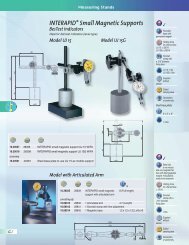
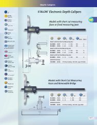
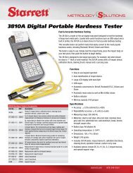
Operating principle<br />
TESASCAN <strong>25</strong> uses high-resolution<br />
linear CCD sensors. Each<br />
sensor is sub-divided into thousands<br />
of light sensitive pixels.<br />
When the part image is projected,<br />
these sensors, which act<br />
as a light sensitive ruler, can<br />
detect the slightest changes at<br />
sub-pixel level.<br />
The workpiece is illuminated<br />
with parallel white light and its<br />
image is projected onto the linear<br />
CCD sensors, which are orientated<br />
to 7.5∞. They provide<br />
the information obtained from<br />
the image, which allows exact<br />
analysis of the geometry of the<br />
workpiece features.<br />
N-2<br />
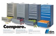
TESASCAN <strong>25</strong><br />
Non Contact Measuring<br />
The optimum solution for<br />
measuring small cylindrical parts<br />
TESASCAN <strong>25</strong> is a dedicated system that provides the optimum solution<br />
for measuring small cylindrical parts with diameters up to <strong>25</strong> mm and<br />
lengths up to 200 mm. This high speed non-contact measuring machine<br />
features an opto-electronic projection system with high-resolution linear CCD<br />
sensors. TESASCAN <strong>25</strong> is a fully automatic, flexible measuring system with<br />
comprehensive measurement capabilities designed to meet the requirements<br />
of round part inspection.<br />
WORK-<br />
PIECE<br />
PROJEC-<br />
TOR<br />
SENSOR 1<br />
WORK-<br />
PIECE<br />
SENSOR 2<br />
Automatic measurement<br />
TESASCAN <strong>25</strong> offers the small round<br />
part manufacturer a more capable, CNC<br />
alternative to traditional hand tools and<br />
other manually-operated equipment and<br />
profile projectors.<br />
Dynamic measurement<br />
Rotation is a standard function of<br />
TESASCAN <strong>25</strong>. This permits rotary<br />
scanning of the workpiece for the measurement<br />
of all external geometric part features<br />
with a combination of high speed<br />
and high accuracy. True 3D alignment<br />
allows a datum axis of the part to be<br />
defined.<br />
Flexible programming<br />
TESASCAN <strong>25</strong> can accept data from<br />
other measuring instruments (e.g., when<br />
inspecting internal dimensions), which<br />
are then included in a single report.<br />
Operator “prompts” can be included in<br />
the part program to<br />
indicate the need for data input from an<br />
external measuring instrument,<br />
at the beginning or the end of a measurement<br />
cycle.<br />
Direct use in the workshop<br />
With high measurement speed and short<br />
programming times, TESA SCAN <strong>25</strong> can<br />
easily be integrated within the overall<br />
manufacturing process and is suitable<br />
for one-off, sample and 100% inspection.<br />
Part program creation within<br />
minutes<br />
The industrial strength software<br />
ProMeasure/ProComposer further<br />
enhances the overall flexibility and speed<br />
of TESASCAN <strong>25</strong>. This highly intuitive<br />
programming module simplifies each<br />
stage of the manufacturing process.<br />
In most cases, simple and complex part<br />
programming is completed in a matter<br />
of minutes.<br />
Compact system design<br />
The TESASCAN <strong>25</strong> comes complete<br />
with all CNC – everything needed<br />
to begin measuring. There are no<br />
external cables other than those used to<br />
link the measuring system to host computer.<br />
TESASCAN <strong>25</strong> is supplied with<br />
computer, video card and peripheral<br />
devices (17” monitor, keyboard and<br />
mouse), as well as<br />
ProMeasure/ProComposer software.
Measurement capability<br />
Non Contact Measuring<br />
Static:<br />
Diameters, Lengths, Intersections, Gage<br />
Diameters, Radii, Angles, etc.<br />
2D workpiece alignment – creation<br />
of a workpiece axis based on two<br />
reference diameters.<br />
Dynamic:<br />
Concentricity – parallel, max. form and gage<br />
diameters, interrupted diameters, tapers and<br />
parallel thread profile.<br />
Radial runout – plain and interrupted diameters.<br />
Face runout.<br />
Roundness, Cylindricity, Straightness.<br />
Diameters with rotation – ovality, max./min.<br />
and average diameters of plain or<br />
interrupted diameters.<br />
Hexagon – across flats dimension, symmetry<br />
of flats relative to an axis, max. dimension<br />
across corners.<br />
Section analysis with rotation – max./min.<br />
section radius and angular position.<br />
Offset diameters – eccentricity and symmetry.<br />
3D workpiece alignment – creation of a<br />
workpiece axis with reference to plain<br />
diameters or a thread profile.<br />
Technical Data – TESASCAN <strong>25</strong><br />
Measuring capacity diameter 1.0 in <strong>25</strong> mm<br />
length 8.0 in 200 mm<br />
Component capacity diameter 2.3 in 59 mm<br />
length 10.6 in 270 mm<br />
weight 4.4 lbs 2 kg<br />
Accuracy* diameter (0.06+0.01D) / 1000 in 1.5+(0.01D) μm<br />
(20±1°C)<br />
length (0.24+0.01L) / 1000 in 6+(0.01L) μm<br />
Resolution diameter 0.00001 in 0.0002 mm<br />
length 0.00004 in 0.001 mm<br />
Repeatability diameter ±0.00004 in ±0.001 mm<br />
±2s=95%<br />
length ±0.0001 in ±0.00<strong>25</strong> mm<br />
Speed diameter 0.2 sec<br />
static measurement<br />
edge 0.2 sec<br />
Weight measuring unit 121 lbs 55 kg<br />
Dimensions<br />
(h x w x d)<br />
system 33 x <strong>25</strong> x 18 in 840 x 640 x 460 mm<br />
Operating conditions temperature 50 - 95°F 10 - 35°C<br />
relative humidity 10 - 80%<br />
Operating voltage 100/110 - 220/240 VAC 50/60 Hz<br />
*D in in/mm L in in/mm<br />
Thread measurement<br />
(with no mechanical tilting):<br />
Parallel, vee-shaped threads – major and<br />
pitch diameters, angle and flank diameters.<br />
Taper threads – major and pitch<br />
diameters at any location, taper, flank<br />
angles, gage length, useable thread length.<br />
Image cleaning:<br />
The software includes a number of<br />
filters which can be selected at<br />
various levels to reduce the effect of<br />
contaminated workpieces.<br />
Performance data is based on results from clean, ground components at 20°C and may be affected by component shape and surface.<br />
N-3
N-4<br />
Measurement capability<br />
Static:<br />
Diameters, Lengths, Intersections,<br />
Gage Diameters, Radii, Angles, etc.<br />
2D workpiece alignment – creation<br />
of workpiece reference axis from<br />
two diameters.<br />
Dynamic:<br />
Concentricity – parallel, max. form<br />
and gage diameters, interrupted<br />
diameters, taper and parallel<br />
thread profile axis.<br />
Runout – plain, interrupted<br />
diameters and face runout.<br />
Straightness.<br />
Diameter with rotation – ovality,<br />
max./min. average diameter of<br />
plain or interrupted diameters.<br />
Hexagon – across flats dimension,<br />
symmetry of flats to axis, max.<br />
dimension across corners.<br />
Section analysis with rotation –<br />
max. and min. section radius and<br />
angular locations.<br />
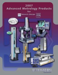
Non Contact Measuring<br />
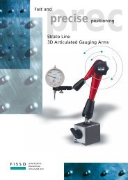
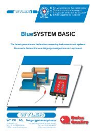
TESASCAN 50<br />
TESASCAN 50 Plus<br />
Measures all common round part geometry,<br />
including small intricate forms like radii and angles<br />
If you're in the business of manufacturing round parts, then TESASCAN 50<br />
and TESASCAN 50 Plus are the ultimate measurement solutions. Developed<br />
by the world’s leading metrology company, Brown & Sharpe, TESASCAN 50<br />
belongs to a new generation of fully automatic and easy to program machines,<br />
developed specifically for the measurement of round and turned components.<br />
The system uses opto-electronic projection which enables the measurement<br />
of all common round part geometry, including small intricate forms like radii<br />
and angles. The major benefit of non-contact technology is the ability to<br />
perform such measurements with a combination of speed, flexibility and<br />
accuracy not previously possible.<br />
Offset diameters – eccentricity<br />
and symmetry.<br />
3D workpiece alignment – creation<br />
of workpiece reference axis from<br />
plain diameters and thread profiles.<br />
Thread measurement<br />
(with slewing mechanism):<br />
Parallel vee-form – major, minor<br />
and pitch diameters, pitch, flank<br />
angles. Additional features with<br />
safety critical option – major,<br />
minor, pitch and functional<br />
diameters, pitch, flank angles,<br />
root radius, taper, lead error,<br />
runout and circularity.<br />
Taper threads – major, minor and<br />
pitch diameters at any location,<br />
pitch, taper, flank angles, gage<br />
length, useable thread length,<br />
crest and root profiles.<br />
Image cleaning:<br />
A software filter which can be set<br />
at different levels to reduce the<br />
effect of contamination on the<br />
workpiece.
Non Contact Measuring<br />
Technical Data – TESASCAN 50/TESASCAN 50 Plus<br />
TESASCAN 50 TESASCAN 50 Plus<br />
Measuring capacity diameter 1.96 in / 50 mm<br />
length 10.8 in / 275 mm 19.7 in / 500 mm<br />
Component capacity diameter 3.9 in / 100 mm<br />
length 11.4 in / 290 mm 20.3 in / 515 mm<br />
weight 8.8 lbs / 4 kg 13.2 in / 6 kg<br />
Tilting for thread<br />
measurement<br />
diameter Max. helix angle 15°<br />
Accuracy diameter (0.08+0.01D)/1000 in / 2+(0.01D) μm<br />
(20±1°C)<br />
length (0.28+0.01L)/1000 in / 7+(0.01L) μm<br />
Resolution diameter 0.00001 in / 0.0003 mm<br />
length 0.00004 in / 0.001 mm<br />
Repeatability diameter ±0.00004 in / ±0.001 mm<br />
±2s=95%<br />
length ±0.0001 in / ±0.00<strong>25</strong> mm<br />
Speed diameter 0.5 sec<br />
static measurement<br />
edge 0.5 sec<br />
Weight measuring unit <strong>25</strong>0 lbs / 115 kg<br />
complete system 350 lbs approx. / 160 kg approx.<br />
Dimensions measuring unit 41 x 32 x 23 in / 1050 x 800 x 580 mm<br />
(h x w x d)<br />
controller 7 x 19 x 21 in / 180 x 480 x 540 mm<br />
Operating conditions temperature 50 - 95°F / 10 - 35°C<br />
relative humidity 10 - 80%<br />
Electrical service 90 - <strong>25</strong>5 VAC and 50/60 Hz<br />
Performance data is based on results from clean, ground components at 20°C and may be affected by component shape and surface.<br />
N-5
N-6<br />
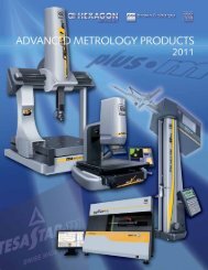
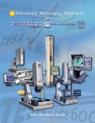
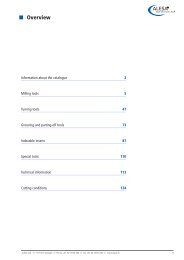
Non Contact Measuring<br />
TESASCAN 80 and 80 PLUS<br />
The new TESASCAN 80 from TESA has all the advantages of a dedicated<br />
machine for non-contact measurement in a shopfloor environment. Due to its<br />
dual-optics, the machine remains as accurate as the smaller TESASCAN <strong>25</strong><br />
machine. The optical configuration allows components with diameters from<br />
0.<strong>25</strong> mm to 80 mm to be inspected with a resolution of 0.000<strong>25</strong> mm throughout<br />
the measuring range. The machine is fully enclosed, thus avoiding direct<br />
access to the mobile parts of the system. The enclosure has an interlocked<br />
sliding door for operator safety. The computer is installed in a safe compartment<br />
located right under the machine.<br />
Significant shortening of inspection cycles<br />
Like any other machine within the TESASCAN family, the servomotor drive used<br />
for the vertical slide allows the high measurement speed of 150 mm/s with accelerations<br />
of 800 mm/s. This high speed performance reduces the inspection cycle significantly.<br />
Common cases where dimensional inspection time could be reduced<br />
from 40 minutes down to less than one minute using our machine are not unusual.<br />
Powerful, user-friendly inspection software<br />
TESASCAN 80 is used in conjunction with PRO-MEASURE/PRO-COMPOSER,<br />
Windows 2000 / XP compliant software. This proven software, which is continuously<br />
updated to meet the market requirements, lets non-experienced staff<br />
expertly perform optical measuring.
Non Contact Measuring<br />
TESASCAN 80 and 80 PLUS<br />
TESASCAN 80 is available in 2 versions:<br />
TESASCAN 80 02430050<br />
Measuring machine with rugged enclosure, DELL GX 280 computer, 15” TFT flat<br />
screen, keyboard and mouse.*<br />
TESASCAN 80 PLUS 02430060<br />
Measuring machine with slew mechanism for thread and worm thread analysis,<br />
DELL GX 280 computer, TFT 15” flat screen, keyboard and mouse.*<br />
*Note: Hardware is supplied with a three-year warranty on site. Additional information<br />
available on request.<br />
Maintenance and calibration<br />
TESASCAN 80 is calibrated at our factory using masters officially recognized by the<br />
<strong>Swiss</strong> Service of Calibration (SCS). TESA recommends annual checking of the<br />
machine accuracy (or twice a year in case of shift work). This is carried out by our<br />
qualified maintenance engineers. TESA offers a periodical servicing on a contract<br />
basis, which also includes a machine conformance testing.<br />
Specifications to TESASCAN 80 02430050<br />
Measuring capacity diameter 3.1 in 80 mm<br />
length 13.8 in (19.7 for TESASCAN PLUS) 350 mm (500 mm for TESASCAN PLUS)<br />
Component capacity diameter 3.9 in 100 mm<br />
length 14.5 in (20.3 for TESASCAN PLUS) 370 mm (515 mm for TESASCAN PLUS)<br />
Accuracy < 30mm diameter (0.06+0.01D) / 1000 in 1.5+(0.01D) μm<br />
length (0.28+0.01L) / 1000 in 7+(0.01L) μm<br />
> 30mm diameter (0.08+0.01D) / 1000 in 2+(0.01D) μm<br />
length (0.32+0.01L) / 1000 in 8+(0.01L) μm<br />
Resolution diameter 0.00001 in 0.0002 mm<br />
length 0.00004 in 0.001 mm<br />
Repeatability diameter ±0.00004 in ±0.001 mm<br />
±2s=95% length ±0.00012 in ±0.003 mm<br />
Air supply pressure 4 - 6 Bar 60 - 90 PSI<br />
Max. component weight 6 kg 13.2 lbs<br />
Specifications to TESASCAN 80 Plus 02430060<br />
Same as TESASCAN 80, but with slew mechanism.<br />
Tilting for thread measurment.<br />
Max. helix angle 10˚<br />
N-7
N-8<br />
Profile 130<br />
Non Contact Measuring<br />
The Profile 130 from Brown & Sharpe has been designed to give the optimum solution<br />
for the measurement of large diameter cylindrical components on the shop floor.<br />
The Profile 130 is based on the proven technology of the smaller TESASCAN 50<br />
machine and brings great flexibility for dimensional measurement to manufacturers<br />
of round and shaft-shaped components up to 5.1 in / 130 mm in diameter.<br />
The Profile 130 consists of an optical measuring head mounted on a vertical slide<br />
that allows it to traverse along the axis of the workpiece supported between headstock<br />
and tailstock. The measuring head incorporates three optical systems and is<br />
moved vertically by means of a toothed belt drive. The drive system is equipped with<br />
an anti-backlash mechanism to give a positional accuracy of about 0.01 µm.<br />
The system<br />
Optical measurement system<br />
utilizing light sensitive linear CCD<br />
arrays.<br />
Fast, easy to use programming software.<br />
CNC-motorized optical measuring head.<br />
Quick release adjustable tailstock.<br />
Headstock with CNC-motorized rotation.<br />
Industry standard Morse 2 quick change<br />
tooling at head and<br />
tailstock.<br />
Full range of workholding options.<br />
Interlocked for operator safety.<br />
Shop-hardened for use in harsh environments.<br />
SPC/SQC options.<br />
Traceability to international<br />
standards.<br />
Measurement capability<br />
Static:<br />
Diameters, Lengths, Intersections, Gage<br />
Diameters, Radii, Angles, etc.<br />
Threads - major, minor and<br />
effective diameters, pitch, flank<br />
angles.(Without slewing)<br />
2D alignment.<br />
Dynamic:<br />
Concentricity - plain and max. form<br />
diameters, diameters on a taper, thread<br />
profile axis.<br />
Radial run-out.<br />
Straightness.<br />
Diameter with rotation, ovality, max. and<br />
min.<br />
Hexagon - across flats dimension and<br />
symmetry, max. dimension across corners.<br />
Profile analysis with rotation - max. and<br />
min. Section radius size and angular<br />
location.<br />
3D alignment - creation of a dynamic<br />
reference axis from two diameters.
Non Contact Measuring<br />
Technical Data – Profile 130<br />
Measuring capacity diameter 5.1 in 130 mm<br />
length 39 in 1000 mm<br />
Component capacity diameter 9.76 in 248 mm<br />
length 41.3 in 1050 mm<br />
weight 66 lbs 30 kg<br />
Accuracy diameter (0.1+0.02D) / 1000 in 2.5+(0.02D) μm<br />
(20±1°C)<br />
length (0.3+0.01L) / 1000 in 8+(0.01L) μm<br />
Resolution diameter 0.00001 in 0.0003 mm<br />
length 0.00004 in 0.001 mm<br />
Repeatability diameter ±0.00006 in ±0.0015 mm<br />
±2s=95%<br />
length ±0.0002 in ±0.005 mm<br />
Speed diameter 1.5 sec<br />
static measurement<br />
edge 1.5 sec<br />
Operating conditions temperature 50 - 95°F 10 - 35°C<br />
humidity 10 - 80%<br />
Electrical service 100 / 110 220 / 240 VAC 50/60 Hz<br />
Performance data is based on results from clean, ground components at 20°C and may be affected by component shape and surface.<br />
N-9
Ø<br />
AB<br />
AB<br />
N-10<br />
Ø<br />
Ø<br />
B<br />
R<br />
A<br />
THREAD<br />
Non Contact Measuring<br />
ProMeasure/ProComposer<br />
Software<br />
ProMeasure/ProComposer software for Windows provides a powerful industrial<br />
strength solution for each stage of the inspection process. The ProComposer<br />
component of the software simplifies the task of creating measurement<br />
programs, while ProMeasure handles the physical and data gatherings of the<br />
measurement device. The software is specially designed for use in a shop<br />
environment. The user-friendly interface makes it possible to use the software<br />
with minimum training and a comprehensive on-line help feature makes it easy<br />
to get assistance anytime.<br />
Graphic programming<br />
interface<br />
ProMeasure/ProComposer software<br />
is simple to use and can either be<br />
installed directly on the TESA -<br />
SCAN <strong>25</strong>, TESASCAN 50,<br />
Profile 80, Profile 130 workstation<br />
or networked to the workstation<br />
enabling a part program to be prepared<br />
off-line. It uses a graphic representation<br />
of the part profile, created<br />
by scanning the workpiece or<br />
importing from a CAD file. A library of<br />
icons, each representing a geometric<br />
function, guide the user in the part<br />
programming sequence. Nominal<br />
and tolerance values of certain<br />
measurement types can easily be set<br />
by retrieving them from databases of<br />
international standards.<br />
Graphic analysis<br />
ProMeasure can be used to<br />
perform a visual inspection of the<br />
actual shape of lines and radii by<br />
comparing part data to nominal data,<br />
making it easy to analyze manufacturing<br />
problems.
Key features<br />
Non Contact Measuring<br />
The ProMeasure measurement<br />
analysis option allows viewing of the actual<br />
measurement points collected by the machine<br />
for each measurement feature. This is particularly<br />
valuable for the analysis of out of tolerance<br />
features. It also provides a graphic representation<br />
of geometry and form for functions<br />
such as roundness and radius form deviation.<br />
ProComposer provides a complete overview<br />
of the program indicating the interdependency<br />
of measurement features. This allows quick<br />
changes to be made to the program without<br />
editing individual features. It also permits the<br />
sequence of displayed results to be set and<br />
measurement features can be switched on and<br />
off allowing instant creation of shorter part<br />
programs from more complex ones.<br />
Flexible reporting and<br />
data transfer<br />
ProMeasure permits the user to show the<br />
measurement results in a variety of formats.<br />
The editing functions allow text, logos and<br />
bitmap images to be included in the reports.<br />
Measurement results can be configured by the<br />
user in any chosen sequence. The e-mail type<br />
commands add to the flexibility of this software<br />
as they allow the operator to click the parameter<br />
header, to choose the display sequence<br />
(e.g., ascending or descending value order) or<br />
to highlight the values that are beyond tolerances.<br />
ProMeasure can be easily networked or<br />
linked to an existing workshop data collection<br />
interface. SPC is available as a standard<br />
option.<br />
N-11
N-1<br />
Options<br />
Non Contact Measuring<br />
TL02-0003 - 10 mm MALE DRIVE CENTER<br />
0 - 10 mm diameter friction-coated male center to rotate<br />
components via their centers.<br />
TL01-0002 - 6 mm CENTER ADAPTOR<br />
Adaptor to fit Morse no.1 taper providing a 6 mm diameter<br />
collet bore. This allows standard tooling<br />
Z173-0920/0921, or any special tooling with a plain<br />
6 mm shank to be fitted at head and tailstock.<br />
TL01-0026 - 6 mm CENTER ADAPTOR<br />
Adaptor to fit Morse no. 2 taper providing a 6 mm diameter<br />
collet bore. This allows standard tooling Z173-<br />
0920/0921, or any special tooling with a plain<br />
6 mm shank to be fitted at head and tailstock.<br />
Z173-0920 - 10 mm FEMALE CENTER -<br />
(requires TL01-0002)<br />
Two jawed 90 degree internal cone center with 6 mm<br />
shank to suit adaptor TL01-0002. Suitable for<br />
components without centers with outside diameters<br />
of 2.5 - 10 mm.<br />
Z173-0920 - 10 mm FEMALE CENTER -<br />
(requires TL01-0026)<br />
Two jawed 90 degree internal cone center with 6 mm<br />
shank to suit adaptor TL01-0026. Suitable for components<br />
without centers with outside diameters of<br />
2.5 - 10 mm.<br />
Z173-0921 - 20 mm FEMALE CENTER -<br />
●<br />
(requires TL01-0002)<br />
Two jawed 90 degree internal cone center with 6 mm<br />
shank to suit adaptor TL01-0002. Suitable for components<br />
without centers with outside diameters of<br />
4 - 20 mm.<br />
Z173-0921 - 20 mm FEMALE CENTER -<br />
(requires TL01-0026)<br />
Two jawed 90 degree internal cone center with 6 mm<br />
shank to suit adaptor TL01-0026. Suitable for components<br />
without centers with outside diameters of 4 - 20 mm.<br />
Z173-0961 - 30 mm PLATTEN<br />
Provides a flat surface of 30 mm diameter on which<br />
disc-shaped components (short but relatively large diameter)<br />
can be rested. Has a Morse no. 1 taper for<br />
use at head or tailstock, and is marked with concentric<br />
rings to aid component centering.<br />
Z173-2020 - 1-15 mm CHUCK<br />
Three jawed chuck with reversible jaws for internal<br />
and external workholding. Fitted with a Morse no.1<br />
taper spindle for use in static and dynamic headstock.<br />
* Can also be used with the TESASCAN 50 and Profile 80, when<br />
used in conjunction with a Morse 2 to 1 reducer (listed on next page).<br />
Z178-3021 - THREAD MEASUREMENT MECHANISM<br />
A computer-controlled slew mechanism for automatic<br />
alignment of the thread profile to the machine optical<br />
system. Includes software for the inspection of parallel,<br />
taper and worm threads.<br />
Maximum 6°<br />
Maximum 15°<br />
Z178-2021 - 40 mm FEMALE CENTER<br />
Two jawed 90 degree internal cone center with Morse<br />
no. 2 spindle. Suitable for components without centers,<br />
with outside diameters of 15 - 40 mm.<br />
TESASCAN/Profile<br />
<strong>25</strong> 50 80 130<br />
●<br />
●<br />
●<br />
●<br />
●<br />
● ● ●<br />
● ●<br />
● ●<br />
● ●<br />
●<br />
●<br />
● ●
Options<br />
Non Contact Measuring<br />
TL01-0027 - MORSE 2 TO 1 REDUCER<br />
A reducing sleeve to allow the use of workholding<br />
options from smaller Profile machines which have a<br />
Morse no. 1 taper.<br />
Z178-0607 - 40 mm FEMALE CENTER<br />
Two jawed 90 degree internal cone center with Morse<br />
no. 2 spindle. Suitable for components without centers,<br />
with outside diameters of 15 - 40 mm.<br />
Z178-20<strong>25</strong> - 80 mm PLATTEN<br />
Provides a flat surface of 80 mm diameter on which<br />
disc-shaped components (short but relatively large<br />
diameter) can be rested. Has a Morse no. 2 taper for<br />
use at head or tailstock, and is marked with concentric<br />
rings to aid component centering.<br />
Z178-2026 - 40 mm MALE DRIVE CENTER<br />
0 - 40 mm diameter friction-coated male center to<br />
rotate components via their centers. Fitted with a<br />
Morse no. 2 taper.<br />
Z178-0610 - 40 mm MALE CENTER<br />
60 degree plain center with Morse no. 2 taper to<br />
hold components with centers or bore diameters<br />
from 15 to 40 mm.<br />
Z178-2020 - 1-50 mm CHUCK<br />
Three jawed chuck with reversible jaws for internal<br />
and workholding. Fitted with a Morse no. 2 taper for<br />
use in static and dynamic headstocks.<br />
Z178-2009 - GRIPPER MECHANISM<br />
A drive mechanism with soft rubber jaws to transmit<br />
positive but floating drive from the headstock to components<br />
held between dead centers. Needed when<br />
dynamic functions are to be measured with reference<br />
to centers. Holding diameter 0 - 68 mm.<br />
TWO JAW FIXTURE<br />
A precision workholding system designed specifically<br />
for small parts and parts without centers. Both<br />
external and internal versions are available together<br />
with a range of interchangeable jaws to suit different<br />
component sizes.<br />
* Can also be used with the TESASCAN 50 and Profile 80, when<br />
used in conjunction with a Morse 2 to 1 reducer (listed above).<br />
GAGEPORT INTERFACE<br />
An interface for the connection of any brand of instrument<br />
to Profile and TESASCAN via the RS-232 port.<br />
Connection to Profile and TESASCAN is made with a<br />
cable which incorporates a separate power supply<br />
for the Gageport. Available for digital instruments and<br />
inductive probes.<br />
NOTE: Special cables may be needed between the<br />
instrument and interface.<br />
TESASCAN/Profile<br />
<strong>25</strong> 50 80 130<br />
● ●<br />
● ●<br />
● ●<br />
● ●<br />
● ●<br />
● ●<br />
● ●<br />
● ●<br />
● ● ● ●<br />
N-13
N-14<br />
Vision Systems<br />
TESAVISIO ® 300 and 300 DCC<br />
The new way of checking complex<br />
parts visually<br />
The innovative TESAVISIO 300 vision measuring system<br />
is available in three models, two manual and one DCC.<br />
Each systems measurement range is 300 mm x<br />
200 mm in (X-Y) x 150 mm range in the Z-axis.<br />
Manual Machine Versions:<br />
These two versions have a coordinate stage<br />
fitted with a quick release system in both<br />
the X and Y axes. This system enables fast<br />
system displacements for locating the<br />
geometric features to be measured.<br />
Disengageable wheel drives are<br />
used for quick motion in the Z-axis<br />
as well as fine setting for focusing<br />
the system.<br />
TESAVISIO 300 manual models<br />
are available with either TESA-VISTA<br />
software or PC-DMIS VISION software.<br />
DCC Machine Version:<br />
On this system, the coordinate stages along<br />
with the vertical axis are displaced by means of<br />
DC servomotors and are user controlled by a<br />
joystick. This allows the user to easily locate<br />
geometric features and provides for automatic motor<br />
driven execution of software driven part application<br />
programs.<br />
The tables of both manual versions<br />
of the TEAVISIO 300 are fitted with<br />
a quick release system in the X and<br />
Y axes to allow fast locating of part<br />
features. Disengageable wheel<br />
drives provide fast movement in<br />
the Z axis and fine setting of the<br />
focal length.
Vision Systems<br />
TESAVISIO 300 DCC Multi-Sensor<br />
The introduction of multi-sensor technology<br />
brings greater flexibility and capability to the<br />
TESAVISIO 300 DCC by combining the features<br />
of the vision system with those of a tactile measurement<br />
system. The result…feature geometry<br />
that is not suited to vision measurement techniques<br />
can, in most cases, be inspected using a<br />
touch trigger probe.<br />
Controlled by PCDMIS Software for both the tactile<br />
and the vision measurements, the TESAVI-<br />
SIO 300 DCC becomes a very powerful and versatile<br />
system. Multi-sensor technology simplifies<br />
the inspection process by reducing the number<br />
of systems required to inspect a component.<br />
With the new multi-sensor VISIO 300 DCC a single<br />
system can be used to inspect a complete part with seamless switching between video and contact<br />
measurement in a fully automatic cycle. To fully automate the measurement process, the Probe Change<br />
rack is an essential tool. Probe heads can be changed automatically within the measurement cycle, without<br />
the need for operator intervention.<br />
Multi-sensor system offers the following main features:<br />
– High accuracy cross probe correlation and calibration<br />
– Multiple probing offsets all linked to a single “tree calibration”<br />
– Full 3D geometry capability<br />
– Ability now to measure the “non viewable” component geometry<br />
– Scanning (option)<br />
Touch Probe Interface, including:<br />
– Required hardware fitted in the machine<br />
– Ring gauge set for optics/touch probe calibration<br />
– Reference Sphere<br />
PCDMIS Tactile for vision software, touch trigger probes,<br />
modules, styli, tips and change rack sold separately.<br />
N-15
N-16<br />
Features<br />
Vision Systems<br />
TESAVISIO ® 300 and 300 DCC<br />
The new way of checking complex parts visually<br />
Pre-stressed carriages mounted on ultra-precise monorails.<br />
Linear encoders mounted an each axis.<br />
Encoder resolution (X/Y/Z) 0.05 µm.<br />
Red laser pointer- helps locating features to be checked.<br />
Long lasting LED light sources.<br />
Transmitted light produced by a green LED with programmable<br />
light intensity.<br />
Reflected light (ring light) created by Fresnel lens<br />
consisting of a dual line of 24 white LEDs. An additional ring light<br />
fragmented into 4 segments is also available. Both ring lights are<br />
programmable.<br />
A programmable coaxial light (white LED) can be supplied for use<br />
in conjunction with the motorized zoom.<br />
High resolution color camera.<br />
Optional 75 mm or 150 mm height extensions allow<br />
easy inspection of large workpieces .<br />
Both manual and DCC VISION models are available with a<br />
0.7X to 4.5X motorized zoom.<br />
The software includes a zoom calibration routine.<br />
The TESA-VISTA manual model with TESA-VISTA software is<br />
available with a 2X telecentric fixed objective.<br />
TESA-VISTA software provides easy-to-use software designed for basic shop floor applications.<br />
PC-DMIS VISION software provides users with a powerful tool for measurement in two and three dimensions<br />
including many programming capabilities. PC-DMIS provides a long-term solution in an ever evolving manufacturing<br />
environment as it can be continuously updated to the latest technology level. All inspection reports<br />
issued in a variety of formats can be custom-made to suit the operator’ s specific needs.<br />
TESA-VISTA Software<br />
Viewing in X, Y or Z-axis with a resolution to 0.05 µm.<br />
Zero setting of displayed axis by just a click.<br />
Metric/inch conversion.<br />
Cartesian and polar coordinates.<br />
Creation and execution of part programs.<br />
Video image storage.<br />
Measured feature drawing shown in the active<br />
window.<br />
Automatic edge detection.<br />
Z measurement with on-screen help and guidance.<br />
Point, radius, diameter, arc of circle, angle, line,<br />
distance (X/Y), slot, Z measurement.<br />
Alignment, perpendicularity, parallelism, theoretical<br />
point, theoretical diameter, translation of X/Y origin<br />
points.<br />
Features and Functions: Point, radius, diameter, arc<br />
of circle, angle, line, slot, distance (X/Y, and Z<br />
Measurement). Provides for alignment, perpendicularity,<br />
parallelism, theoretical point, theoretical diameter<br />
and translation of X/Y origin points.<br />
PC-DMIS VISION Software<br />
PC-DMIS software has a 20,000 installed base for a<br />
single software solution across multiple products.<br />
Automatic edge detection.<br />
Acquisition of a higher number of points to make<br />
the measurement of shape and form deviation<br />
more accurate.<br />
CAD file import (various formats).<br />
User-friendly point and click programming.<br />
Off-line program sequences.<br />
Reverse engineering with CAD file export option.<br />
Automatic recognition of used magnification without<br />
the need to recalibrate the objective inside an<br />
application program.<br />
Automatic or manual control of the tools.<br />
Z axis measurement made easier through computer<br />
aided focusing in graph mode.<br />
On-screen viewing of the measured values, including<br />
those related to the position of geometric elements<br />
and edge capture.<br />
...Plus all the features included with TESA-VISTA<br />
Software.
SPECIFICATIONS<br />
Available<br />
– Not Available<br />
Vision Systems<br />
Video machine TESA-VISIO 300 TESA-VISIO 300 TESA-VISIO 300 DCC<br />
Software TESA-VISTA PCDmis PCDmis<br />
Machine version Manual Manual Motorized<br />
Measuring spans X/Y (mm) 300 x 200 300 x 200 300 x 200<br />
Measuring span Z (mm) 150 150 150<br />
DC servomotors X/Y/Z – –<br />
X and Y quick release system –<br />
Manual focus, coarse and fine settings –<br />
Profile illumination with 1 green LED<br />
X/Y-Accuracy at 20°C 3+10 L/1000 3+10 L/1000 2,4+4 L/1000<br />
Z-Accuracy at 20°C 3+2 L/100* 3+2 L/100* 3+1 L/100*<br />
Encoder resolution (X/Y/Z) 0.05 µm 0.05 µm 0.05 µm<br />
High-resolution color camera<br />
Red laser pointer<br />
Max. perm. load (in the middle of the stage) 16 kg 16 kg 16 kg<br />
Size (monitor and PC not included) (LxHxD in mm) 680 x 990 x 800 680 x 990 x 800 680 x 990 x 800<br />
Weight (monitor and PC not included) 78 kg 78 kg 78 kg<br />
Operating temperature range 20°± 2°C 20°± 2°C 20°± 2°C<br />
Power supply 115 to 220 Vac ±10% 115 to 220 V ±10% 115 to 220 V ±10%<br />
Z height extension, 75 mm (Z)<br />
Z height extension, 150 mm (Z)<br />
DELL Computer GX 280, 512 MB, 2,53 GHz, 40 GB HD<br />
50 to 60 Hz 50 to 60 Hz 50 to 60 Hz<br />
DELL Monitor TFT, 15" – –<br />
Touch screen monitor, 15" – –<br />
DELL Monitor TFT, 17"<br />
Keyboard according to language (FR, CH, DE, IT, ES, GB, USA, NO, SE, FI, DK)<br />
*Accuracy obtained with use of the motorized zoom at highest magnification<br />
on a textured surface<br />
SOFTWARE COMPONENTS<br />
PC-DMIS-Vision PRO (manual software) – –<br />
PC-DMIS-Vision CAD (manual software) – –<br />
PC-DMIS DCC PRO (motorized version) – –<br />
PC-DMIS DCC CAD(motorized version) – –<br />
Upgrade PC-DMIS PRO / CAD (manual software) – –<br />
Updrade PC-DMIS DCC PRO / DCC CAD<br />
QC CALC from Prolink software<br />
Data Page from SPC software<br />
SPC software QC CALC from Prolink software for the analysis of collected data<br />
and the creation of SPC charts.<br />
– –<br />
OPTICS<br />
Video machine TESA-VISIO 300 TESA-VISIO 300 TESA-VISIO 300 DCC<br />
Software TESA-VISTA PC-DMIS PC-DMIS<br />
Machine version<br />
Motorized zoom<br />
Motorized zoom with coaxial light (white LED)<br />
Manual Manual Motorized<br />
Telecentric fixed objective, 2x<br />
Lens, 0.5x<br />
Lens, 0.75x<br />
Lens, 1.5x**<br />
Lens, 2x**<br />
– –<br />
ILLUMINATION<br />
Ring light (48 white LEDs)<br />
Fragmented ring light (4 x 90° programmable segments)<br />
**Lens with magnifications 1.5x and 2x require the use of the zoom with coaxial light.<br />
N-17
N-18<br />
Optical Comparators<br />
TESASCOPE® II 355H<br />
For measurement of round and complex parts<br />
These dedicated modular systems are made to measure round and complex<br />
parts on the shop floor, as well as in the metrology laboratory. They are provided<br />
with a TS-100, TS-300 or TS-300E calculating and readout box.<br />
Measured parts<br />
Round and complex parts of all kinds that need to be regularly inspected.<br />
Features:<br />
14" (355 mm) diameter rotary screen with chart<br />
clips, cross line 30°, 60°, 90°<br />
Solid steel construction<br />
Profile illumination with green filter<br />
fiber-optic surface illumination<br />
“Save Lamp” system (lamps switch off<br />
automatically if there is no stage movement during<br />
several minutes, increasing the life of the bulb)<br />
Quick change bayonet lens mount<br />
(lenses not included)<br />
RS-232C output for data transfer<br />
Drawings side mount<br />
Hard anodized stabilized stage with<br />
clamping slot for tooling, equipped with linear<br />
glass scales with 0.0001 in/0.001 mm resolution<br />
Focus travel: 3.15" (80 mm)<br />
Maximum weight on stage: 40 lbs (20 kg)<br />
Built-in angular readout (degrees/minutes)<br />
Calibration certificate according to VDI- VDE 2617 – B89 4.1.1997<br />
Dimensions: 36" x 43" x 51" (L x H x D)/500 x 912 x 1093 mm<br />
Weight: 240 lbs (110 kg)<br />
Power supply: 110 Vac – 50 Hz/230 Vac<br />
TESA-Scope II 355H<br />
Order No. EDP NO. Description Meas. table 8x4 in/ 200x100 mm TS-100 TS-300 TS-300E<br />
06830051 24792 TESA-Scope II 355H ✓ ✓<br />
06830052 24793 TESA-Scope II 355H ✓ ✓<br />
06830053 24794 TESA-Scope II 355H E ✓ ✓<br />
TESA-Scope II PLUS 355H<br />
Order No. EDP NO. Description Meas. table 12x4 in/ 200x100 mm TS-100 TS-300 TS-300E<br />
06830054 24795 TESA-Scope II PLUS 355H ✓ ✓<br />
06830055 24796 TESA-Scope II PLUS 355H ✓ ✓<br />
06830056 24797 TESA-Scope II PLUS 355H ✓ ✓<br />
Magnification 10 x<br />
Lens length and<br />
20 x 50 x<br />
lens body length 1.18 in/30 mm 1.26 in/32 mm 2.48 in/63 mm<br />
Working distance 3.15 in/80 mm 3.23 in/82 mm 2.09 in/53 mm<br />
Maximum height 3.94 in/100 mm 3.94 in/100 mm 3.94 in/100 mm<br />
Maximum diameter 7.87 in/200 mm 7.87 in/200 mm 7.87 in/200 mm
Optical Comparators<br />
TESASCOPE ® II 300V<br />
Reliable and dependable<br />
The high quality of the projected image provides the operator with reliability and<br />
dependability for accurate measurements. A wide choice of accessories adds to<br />
the remarkable flexibility of these optical systems with modular design.<br />
The multiple configurations allow any geometric part feature to be<br />
easily measured.<br />
Measured parts<br />
These profile projectors are ideally suited for non-contact measurement<br />
of components that require a magnification up to 100x<br />
– whatever their material or their shape.<br />
Features:<br />
12" (300 mm) diameter rotary screen with chart clips, cross line 30°, 60°, 90°<br />
Solid steel construction<br />
Profile illumination with green filter<br />
fiber-optic surface illumination<br />
“Save Lamp” system (lamps switch off automatically if there is no stage movement<br />
during several minutes, increasing the life of the bulb)<br />
Quick change bayonet lens mount (lenses not included)<br />
RS232C output for data transfer<br />
Drawings side mount<br />
Hard anodized stabilized stage with clamping slot for tooling,<br />
equipped with linear glass scales with 0.0001 in/0.001 mm resolution<br />
Focus travel: 4" (100 mm)<br />
Maximum weight on stage: 40 lbs (20 kg)<br />
Built-in angular readout (degrees/minutes)<br />
Calibration certificate according to VDI- VDE 2617 – B89 4.1.1997<br />
Dimensions: 20" x 41" x 31" (L x H x D)/508 x 1042 x 788 mm<br />
Weight: 240 lbs (110 kg)<br />
Power supply: 110 Vac – 50 Hz/230 Vac<br />
TESA-Scope II 300V PLUS<br />
Order No. EDP NO. Description 12 x 4 in / Meas. table 300x100 mm TS 100 TS 300 TS 300E<br />
06830044 23116 TESA-Scope II 300V PLUS ✓ ✓<br />
06830045 23170 TESA-Scope II 300V PLUS ✓ ✓<br />
06830046 23171 TESA-Scope II 300V PLUS ✓ ✓<br />
Magnification 10 x<br />
Lens length and<br />
20 x 50 x<br />
lens body length 1.18 in/30 mm 1.26 in/32 mm 2.48 in/63 mm<br />
Working distance 3.15 in/80 mm 3.23 in/82 mm 2.09 in/53 mm<br />
Maximum height 3.94 in/100 mm 3.94 in/100 mm 3.94 in/100 mm<br />
Maximum diameter 7.87 in/200 mm 7.87 in/200 mm 7.87 in/200 mm<br />
N-19
N-20<br />
Optical Comparators<br />
TESASCOPE ® 500V<br />
Excellent Price/Performance Ratio —<br />
Complete with a wide number of standard accessories<br />
Measured parts<br />
Large to mid-sized parts with flat surfaces that require a magnification<br />
up to 100x as well as soft and cutting components up to 12" (300 mm).<br />
Features:<br />
500 mm (20") diameter rotary screen with chart clips, cross line 30°, 60°, 90°<br />
Solid steel construction<br />
Profile illumination with green filter<br />
fiber-optic surface illumination<br />
Quick change lens mount<br />
“Save Lamp” system (lamps switch off automatically if there is no stage<br />
movement during several minutes, increasing the life of the bulb)<br />
RS-232C output for data transfer<br />
Drawings side mount<br />
Hard anodized stabilized stage with clamping slot for tooling, equipped<br />
with linear glass scales with 0.0001 in/0.001 mm resolution<br />
Focus travel: 3" (70 mm)<br />
Measure travel: X = 9"/Y = 4" (X = 200/Y = 100 mm)<br />
(quick release with fine adjustment)<br />
Maximum weight on stage: 40 lbs (20 kg)<br />
Hood and curtain<br />
Built-in angular readout (degrees/minutes)<br />
Calibration certificate according to VDI- VDE 2617 – B89 4.1.1997<br />
Dimensions: 39" x 78" x 52" (L x H x D)/1000 x 1996 x 1318 mm<br />
Weight: 450 lbs (200 kg)<br />
Power supply: 110 Vac – 50 Hz/230 Vac<br />
TESA-Scope 500V fitted with a system that enables the user to choose between 2 objectives<br />
Order No. EDP NO. Description 8x4 in / Meas. table 200x100 mm TS 100 TS 300 TS 300E<br />
06830064 24801 TESA-Scope II 500V – TS100 ✓ ✓<br />
06830065 24802 TESA-Scope II 500V – TS300 ✓ ✓<br />
06830066 24803 TESA-Scope II 500V – TS300E ✓ ✓<br />
Magnification<br />
Lens length and<br />
10 x 20 x 50 x<br />
lens body length 3.43 in/87 mm 3.23 in/82 mm 2.4 in/61 mm<br />
Working distance 3.15 in/80 mm 3.15 in/80 mm 3.15 in/80 mm<br />
Maximum height 4.33 in/110 mm 4.33 in/110 mm 4.33 in/110 mm<br />
Maximum diameter 6.3 in/160 mm 6.3 in/160 mm 6.3 in/160 mm
TS300E with<br />
edge detector<br />
Optical Comparators<br />
TS-100<br />
– X/Y readout<br />
– 0.0001 in/0.001 mm resolution<br />
– Inch/Metric switchable<br />
– Independent zero reset (X/Y)<br />
– Absolute and incremental<br />
measurement<br />
– X/Y Linear compensation<br />
– Illumination control – profile<br />
and surface<br />
– RS-232 output (SPC Printer)<br />
– Diameter: 3 to 10 entered points<br />
– Radius: 3 to 10 entered points<br />
– Distances from the last datum radius or<br />
diameter<br />
– Auto Enter function<br />
- RS-232 and Parallel Options<br />
– Skew<br />
– Point<br />
– Radius<br />
– Diameter<br />
–Arc<br />
Accessories<br />
– Angle<br />
– Line<br />
– Distance<br />
– Slot<br />
– Perpendicularity<br />
Telecentric lenses for TESASCOPE® 300V - 355H<br />
06860001 300V-355H 10 x Telecentric lens<br />
06860002 300V-355H 20 x Telecentric lens<br />
06860005 300V-355H 50 x Telecentric lens<br />
Telecentric lenses for TESASCOPE® 500V<br />
06860008 500V 10 x Telecentric lens<br />
06860009 500V 20 x Telecentric lens<br />
06860012 500V 50 x Telecentric lens<br />
Accessories for all TESASCOPE®<br />
06860015 200 x 100 mm glass stage/300V<br />
06860016 300 x 150 mm glass stage/300V PLUS<br />
06860017 300V screen with 4 chart clips<br />
06860018 355H screen with 4 chart clips<br />
06860019 500V screen with 4 chart clips<br />
06860020 Profile lamp (24 V-150 W)<br />
06860021 Surface lamp (24 V-150 W)<br />
06860023 Remote foot switch<br />
068600<strong>25</strong> Vise stage/300V – 500V – 355H<br />
06860026 Vise stage with fixture base/355H<br />
06860027 TESA demo part<br />
TS-300 and TS-300 E<br />
TS-300 Control Panel with<br />
TESA Reflex Software –<br />
- Allows operators to perform 1D and 2D<br />
measurement routines quickly and easily<br />
without the need for keyboard entry routines<br />
- Identifies geometric elements, automatically<br />
draws the workpiece, and calculates their<br />
dimensions and relationships<br />
- Geometric features: Point - Line - Circle<br />
- Measured functions: Alignment -<br />
Measurement with references, translation,<br />
rotation<br />
- Construction features: Intersection - Bolt Hole<br />
Circles - Lines<br />
- LCD Screen<br />
- 0.00005”/0.001mm Resolution<br />
- Inch/Metric Switchable<br />
- Cartesian and Polar coordinates<br />
- Programming functions<br />
- X/Y Linear Compensation<br />
- Part View Printing<br />
- RS-232 and Parallel Options<br />
- Edge Detection (Optional TS-300E)<br />
– Parallelism<br />
– Given point<br />
– Given diameter<br />
– Auto Enter function<br />
N-21
N-22<br />
Measuring Microscopes<br />
ETALON ® TCM 50 Measuring Microscope<br />
Provides simplicity and user comfort – 4 x 2 in / 100 x 50 mm measuring span –<br />
0.0001 in or 0.001 mm numerical interval – High-precision – Built-in<br />
transmitted and oblique incident light – Eyepiece with angle device –<br />
RS-232 digital output – In-house calibration certificate.<br />
06839000 ETALON TCM 50 measuring microscope<br />
Consisting of the following components :<br />
1 TCM 50 measuring microscope, complete.<br />
Measuring table (4 x 2 in / 100 x 50 mm measuring span) with opto-electronic<br />
system and cable for the transmission of the measure ment signal.<br />
Height adjustable optics holder. Monocular viewing tube. Objective for 30x<br />
magnification. Eyepiece with angle device. Built-in transmitted light and<br />
oblique incident light with continuous brightness setting.<br />
1 A 50 Computing counter.<br />
Up/down counter with a two-line numerical display (X and Y, 7-digit display).<br />
Numerical interval 0.001 or 0.0001 in. RS-232 digital output.<br />
Supplied with :<br />
1 Mains adapter, 100 to 240 Vac, 47 to 63 Hz, 11 to 13 Vdc, 30 W.<br />
1 Dust cover.<br />
Optional accessories<br />
06869027 Set of clamping components (listed individually on page N-9).<br />
Main instrument with<br />
measuring table<br />
4 x 2 in<br />
100 x 50 mm<br />
Ball-bearing<br />
measuring table.<br />
Moves freely or over<br />
the threaded spindle<br />
with quick action drive.<br />
Workpiece attachment<br />
with two M8 threads.<br />
Max. perm. load: 11 lbs.<br />
Optics holder with<br />
adjustable height by<br />
means of the wide<br />
knurled collars mounted<br />
on each side.<br />
Opto-electronic<br />
measuring<br />
system with incremental<br />
steel scale<br />
.0001 in<br />
0.001 mm<br />
Valid for<br />
one coordinate<br />
direction plus working<br />
temperature range:<br />
10 μm + 0.04 . L μm<br />
(L = mm)<br />
Optics<br />
Upright,<br />
laterally correct image<br />
30x<br />
Monocular<br />
eyepiece with<br />
dioptric compensation.<br />
Rotating graticule.<br />
Built-in device for angle<br />
measurement: angle<br />
scale value 1°, readout<br />
12' (assessment)<br />
Objective 2 : 1<br />
Object-field diameter<br />
.<strong>25</strong>6 in / 6.5 mm<br />
Numerical aperture<br />
0.05<br />
Free working distance<br />
4 in / 100 mm<br />
(see drawing)<br />
Integrated transmitted<br />
light and oblique incident<br />
light with continuous<br />
brightness setting,<br />
5 W each
TCM 50 counter<br />
Two-line<br />
LC display<br />
(coordinates X/Y)<br />
7 digits and<br />
7 segments per sign<br />
0.0001 in or<br />
0.001 mm<br />
.354 in<br />
9 mm<br />
Keyboard protected<br />
against<br />
the penetration of liquids<br />
RS-232<br />
TCM 50 General<br />
Information<br />
Main instrument<br />
with counter:<br />
mains adapter 100 to<br />
240V, 47 to 63 Hz, 11<br />
to 13 Vdc, max. 30 W<br />
32 °F to 122 °F<br />
68 °F ± 32.9 °F<br />
- 4.0 °F to 158 °F<br />
Counter<br />
protection:<br />
IP52 (IEC 60529)<br />
EN 50081-1,<br />
EN 50082-2,<br />
EN 61000-3-2,<br />
EN 61000-3-3<br />
18 lbs.<br />
(microscope)<br />
1 lb. (counter)<br />
Transport<br />
packing<br />
Identification<br />
number<br />
In-house calibration<br />
certificate<br />
Declaration<br />
of conformity<br />
Measuring Microscopes<br />
ETALON® TCM 50 Measuring Microscope<br />
N-23
N-24<br />
Measuring Microscopes<br />
68.69027<br />
06869027 Set of clamping components<br />
Suitable for ETALON microscopes<br />
TCM 50, TCM 100 and TCM 200 as well as ETALON<br />
profile projector PP 300.<br />
Consisting of:<br />
68.69028 1 SU articulated support<br />
Dual-arm support with central clamp through the star<br />
grip. Total length 7.7 in / 195 mm. With 1 socket joint<br />
and 2 ball joints. M8 fixing thread on the table side<br />
and .197 in / 5 mm dia. fixing hole on the workpiece<br />
side. Max. perm. load: 14 oz. / 400 g.<br />
Clamps for attaching the SU support on the measuring table<br />
T-slot blocks, type ETALON / LEICA.<br />
T-slot blocks with M8 fixing thread for articulation.<br />
68.69029 1 Item, type V for vertical position.<br />
68.69030 1 Item, type H for horizontal position.<br />
Workpiece-oriented clamps for use with the SU support<br />
With a .197 in / 5 mm dia. fixing hole.<br />
Spring clamp to hold workpieces down.<br />
68.69031 1 Item, 1.34 in / 34 mm long.<br />
68.69032 1 Item, 1.97 in / 50 mm long.<br />
68.69033 1 P clamp for small parts, max. clamp capacity.<br />
≤ .071 in / 1.8 mm, resting width .118 in / 3 mm, depth<br />
stop at .060 in / 1.5 mm.<br />
68.69034 1 M clamp for small parts, max. clamp capacity.<br />
≤ .197 in / 5.0 mm, resting width .19 in / 4.8 mm,<br />
depth stop at .060 in / 1.5 mm.<br />
68.69035 1 Clamping chuck, ≤ .118 in / 3 mm dia.<br />
68.69036 1 Toggle clamp, clamping capacity ≤ .98 in / <strong>25</strong> mm<br />
68.69037 1 V-block with spring clamp covering a range from<br />
.080 to .98 in / 2 to <strong>25</strong> mm. Vee angle 120°. Vee<br />
length .98 in / <strong>25</strong> mm.<br />
68.69038 1 Try square, beam length 4.73 x 3.15 in / 120 x 80 mm.<br />
Accommodates 2 T-grooves for both columns<br />
No 68.69039.<br />
68.69039 2 Columns used with the try square for attaching the<br />
spring clamps listed below.<br />
Spring clamp to hold the workpieces down.<br />
68.69040 1 Item, 1.34 in / 34 mm long.<br />
68.69041 1 Item, 1.97 in / 50 mm long.<br />
Leaf spring clamp to press the workpiece against<br />
the try square.<br />
68.69042 1 Item, 1.34 in / 34 mm long.<br />
68.69043 1 Item, 1.97 in / 50 mm long.<br />
68.69044 1 Adapter rotating through 4 x 90° with<br />
lock-in positions.<br />
1 Socket head key (2, 2.5 and 3 mm).<br />
1 Clamping bolt for holes with a 5 mm dia.<br />
68.69031<br />
68.69033<br />
68.69035<br />
68.69037<br />
M8<br />
68.69029<br />
68.69038 – 68.69039 – 68.69040 – 68.69042<br />
68.69028<br />
ø 5 mm<br />
✓<br />
Wooden case<br />
Declaration<br />
of conformity
Main instrument with<br />
measuring table<br />
150 x 100 mm<br />
<strong>25</strong>0 x 150 mm<br />
Main<br />
part in<br />
cast iron.<br />
Optics holder guided<br />
on a ball-bearing,<br />
height adjustable using<br />
the feed knobs for fast<br />
and fine focusing,<br />
max. travel 150 mm.<br />
Steel ball-bearing<br />
measuring tables<br />
equipped with optoelectronic<br />
systems<br />
having incremental<br />
steel scales.<br />
Valid for one<br />
coordinate direc -<br />
tion as well as the<br />
working temperature range:<br />
1.8 μm + 0.005 · L μm<br />
for the table 150 x 100<br />
2.5 μm + 0.01 · L μm<br />
(L in mm)<br />
for the table <strong>25</strong>0 x 150<br />
Illumination<br />
system<br />
Coaxial reflected<br />
light and trans -<br />
mitted light with<br />
knurled wheel used for<br />
setting the diaphragm<br />
aperture.<br />
Light units with remote<br />
continuous brightness<br />
setting.<br />
fiber-optic illumination<br />
Optical system<br />
Binocular<br />
viewing tube<br />
with dioptric<br />
compensation for each<br />
eyepiece.<br />
Eyepiece cups 10 x<br />
magni fication.<br />
20 mm dia. free opening<br />
<strong>25</strong>° viewing angle.<br />
Upright, laterally correct<br />
image.<br />
For interchangeable<br />
objectives and microobjectives<br />
with bayonet<br />
mount.<br />
Optical Measurement<br />
ETALON TCM 200<br />
Measuring Microscope<br />
Modular concept – Custom built configurations for optical applications<br />
from length measurement through metallographic examination – Selectable telecentric<br />
objectives of superior quality – Optimum object illumination –<br />
Ball-bearing measuring tables having a 150 x 100 mm or <strong>25</strong>0 x 150 mm meas -<br />
uring span – Opto-electronic measuring systems with incremental<br />
steel scales – Computer based data processing – RS-232 digital output –<br />
In-house calibration certificate.<br />
Non-contact measurement in 1, 2 or 3 coordinate directions.<br />
Numerical interval to 0.0005 mm or 0.00002 in.<br />
High accuracy guaranteed by a very low maximum permissible error<br />
–2.6 µm only over a 150 mm measured length, for instance.<br />
High load capacity and long free working distances for the inspection<br />
of tall test pieces.<br />
Bright images for surface structure examination with magnifications<br />
up to 1000 x.<br />
Video camera for further image analysis.<br />
N-<strong>25</strong>
N-26<br />
Optical Measurement<br />
ETALON TCM 200 made ready-for-use – Ordering Variations<br />
Equipped with binocular viewing tube for metrology oriented applications (for 230 V).<br />
Additional technical data and ordering information as listed below.<br />
Variations<br />
Main<br />
instrument<br />
with binocular<br />
viewing tube<br />
Cold light unit<br />
transmitted reflected<br />
light light<br />
35 W 90 W<br />
Meas. table<br />
Meas. span<br />
150 x 100 <strong>25</strong>0 x 150<br />
mm mm<br />
Coordinate<br />
direction<br />
Z<br />
QUADRA-CHEK<br />
220 230* 4000<br />
06839006 1 ● ● ● ● ● ●<br />
06839007 2 ● ● ● ● ● ●<br />
06839008 3 ● ● ● ● ●<br />
06839009 4 ● ● ● ● ●<br />
06819006 5 ● ● ● ● ● ❍<br />
06819007 6 ● ● ● ● ● ❍<br />
06819008 7 ● ● ● ● ❍<br />
06819009 8 ● ● ● ● ❍<br />
* Execution for X, Y and Z coordinate directions: ETALON No. 06839014.<br />
❍ Not part of the sales program. Must be ordered on the spot.<br />
Highly significant features<br />
Table freely moved by hand or fine displacement over<br />
the threaded spindle allowing quick positioning in each<br />
direction.<br />
Objectives with bayonet mount for easy exchange with<br />
just one hand.<br />
Inserts with crossline graticules and concentric circles.<br />
Patented angle device with digital measuring system<br />
(as pictured opposite)<br />
Center support for use in conjunction with the insert<br />
fitted with both aperture diaphragm and interference<br />
slit used to check diameters on cylinders (as pictured<br />
opposite).<br />
Fiber-optic illumination to eliminate all heat lighting.<br />
Image viewing in transmitted light, coaxial reflected<br />
light, oblique incident light and ring light as well as<br />
brightfield/darkfield. Also with or without polarized<br />
light or interference contrast (DIC).<br />
Dedicated compact counter for 2 and 3 coordinate<br />
directions.<br />
Software for value processing using a computer unit.<br />
General<br />
10 °C to 40 °C<br />
20 ± 0.5 °C<br />
–10 °C to 60 °C<br />
120 to 230 Vac<br />
50 to 60 Hz<br />
Protection IP40<br />
(IEC 60529)<br />
EN 50081-1,<br />
EN 50082-1,<br />
EN 61000-4,<br />
EN 61010-1<br />
70 kg net<br />
(main instrument<br />
No. 06819010)<br />
45 kg<br />
(table 150 x 100)<br />
70 kg<br />
(table <strong>25</strong>0 x 150)<br />
Setting key<br />
and dust cover<br />
Shipping<br />
packaging<br />
Identification<br />
number<br />
In-house<br />
calibration<br />
certificate<br />
Declaration<br />
of conformity
Optical Measurement<br />
ETALON TCM 200 Key Components<br />
TCM 200 Main <strong>Instruments</strong> – General Overview<br />
Important: In order to let you work with your microscope efficiently, at least the<br />
following components must be added to all main instruments:<br />
Measuring table<br />
Cold light source for transmitted and reflected illumination<br />
Computing counter for value processing<br />
06819010 Main instrument with binocular viewing tube ●<br />
06819011 Main instrument binocular viewing tube and measuring system (Z) ●<br />
06819012 Main instrument video viewing tube ●<br />
06819013 Main instrument video viewing tube and measuring system (Z) ●<br />
Consisting of:<br />
1 TCM 200 main body ● ● ● ●<br />
1 Optics holder with both mechanically operated fast and fine displacement ● ● ● ●<br />
1 Digital measuring system in the Z direction ● ●<br />
1 Binocular viewing tube ● ●<br />
1 Video viewing tube ● ●<br />
2 Eyepieces with a 10 x magnification (order number for 1 item) ● ●<br />
1 Measuring objective 2 : 1 ● ● ● ●<br />
1 Insert with aperture diaphragm ● ● ● ●<br />
N-27
N-28<br />
Optical Measurement<br />
Components and Use of Accessories – General Overview<br />
To be used with: Binocular Viewing Tube ●<br />
Video Viewing Tube ●<br />
Measuring System in the Z Direction ●<br />
To be used for: Length Measurements ●<br />
Surface Examination in polarized light ●<br />
Surface Examination with Interference Contrast DIC ●<br />
06869061 150 x 100 measuring table ● ● ● ● ● ●<br />
06869062 <strong>25</strong>0 x 150 measuring table ● ● ● ● ● ●<br />
06869063 CLS 50 cold light source for transmitted light 12 V 35 W for 230 Vac ● ● ● ● ● ●<br />
06869064 120 Vac ● ● ● ● ● ●<br />
06869003 CLS 100 for reflected light and oblique incident light 14.5 V 90 W for 230 Vac ● ● ● ● ●<br />
06869006 120 Vac ● ● ● ● ●<br />
06869065 CLS 150 for reflected light and oblique incident light 15 V 150 W for 230 Vac ● ●<br />
06869066 120 Vac ● ●<br />
06869069 Insert with crosslines graticule ● ● ●<br />
06869070 Insert with crosslines graticule and concentric circles ● ● ●<br />
06869071 Angle device with measuring system (Q) ● ● ●<br />
LEICA Plan Achromat telecentric measuring objectives<br />
06869008 Lateral amplification 1 : 1 Total magnification 10x ● ● ● ●<br />
06869009 5 : 1 50x ● ● ● ●<br />
06869010 10 : 1 100x ● ● ● ●<br />
06869011 20 : 1 200x ● ● ● ●<br />
06869072 Center support (for use with the 150 x 100 measuring table only) ● ● ● ●<br />
06869073 Insert with aperture diaphragm and interference slit ● ● ● ●<br />
06869002 Illumination unit with oblique incident light (objectives 1 : 1 to 10 : 1) ● ● ● ●<br />
06869074 Illumination unit with ring light ● ● ● ●<br />
06869075 Micro-optical head for 6 micro-objectives ● ● ◗ ◗ ◗ ◗<br />
06869076 Micro-optical head for 6 micro-objectives and polarized light ● ● ◗ ◗ ◗ ◗<br />
06869019 Single bayonet mount ● ● ◗ ◗ ◗ ◗<br />
LEICA Plan Fluor micro-objectives for image viewing in polarized light (optional)<br />
06869012 Objective 2.5 : 1 Total magnification <strong>25</strong>x ● ● ◗ ◗ ◗ ◗<br />
06869013 5 : 1 50x ● ● ◗ ◗ ◗ ◗<br />
06869014 10 : 1 100x ● ● ◗ ◗ ◗ ◗<br />
06869015 20 : 1 200x ● ● ◗ ● ◗ ◗<br />
06869016 40 : 1 400x ● ● ◗ ● ◗ ◗<br />
06869017 50 : 1 500x ● ● ◗ ● ◗ ◗<br />
06869018 100 : 1 1000x ● ● ◗ ● ◗ ◗<br />
06869077 Micro-optical head for 6 micro-objectives and image viewing in polarised light<br />
with interference contrast DIC ● ● ◗ ◗ ◗ ◗<br />
LEICA Plan Fluor micro-objectives for image viewing in polarised light or not, but<br />
with interference contrast DIC<br />
06869078 Objective 10 : 1 Total magnification 100 x ● ● ◗ ◗ ◗ ◗<br />
06869079 20 : 1 200 x ● ● ●<br />
06869080 40 : 1 400 x ● ● ●<br />
06869081 50 : 1 500 x ● ● ●<br />
06869082 100 : 1 1000 x ● ● ●<br />
06839013 QUADRA-CHEK 220 for 2 coordinate directions (X and Y) ● ● ●<br />
06839014 QUADRA-CHEK 230 for 3 coordinate directions (X, Y and Z) ● ● ● ●<br />
06839015 QUADRA-CHEK 231 for 3 coordinate directions (X, Y and Z) plus angle (Q) ● ● ●<br />
QUADRA-CHEK 4000 software (available on request) ● ● ● ●<br />
Video system (available on request) ● ● ● ● ● ●<br />
06869083 C-mount adapter with 1.2 x magnification ● ● ● ● ●<br />
06869084 C-mount adapter with built-in magnification changer (0.4 x and 1.2 x) ● ● ● ● ●<br />
06869020 KAPPA FK1/F electronic graticule ● ● ●<br />
06869027 Set of clamping components ● ● ● ● ● ●
Optical Measurement<br />
Main <strong>Instruments</strong><br />
06819010 Main instrument with<br />
binocular viewing tube for<br />
ETALON TCM 200<br />
(measuring table and computing<br />
counter excluded)<br />
Consisting of the following components:<br />
1 TCM 200 main body, cast iron, varnished.<br />
Vertical columm with guide adjusted to the<br />
optiques holder No. 06869086 (max. dis pla ce -<br />
ment 150 mm). fiber-optic transmitted light<br />
illumination.<br />
1 Optics holder<br />
With mechanically operated knurled collars<br />
for fast and fine focusing. Accommodates an<br />
attachement for the viewing tube.<br />
1 Binocular viewing tube<br />
Provided with dioptric compensation<br />
for each eyepiece, single bayonet mount<br />
for LEICA Plan Achromat and Plan Fluor<br />
objectives or the micro-optical head, ocular<br />
accommodated attachment, video camera<br />
adapter (C-mount) and angle device.<br />
Coaxial reflected illumination via<br />
fiber-optic.<br />
2 Eyepieces<br />
With a 10x magnification and cups<br />
(order number for 1 item only)<br />
1 Measuring objective 2 : 1<br />
Free working distance a = 85 mm<br />
1 Insert with aperture diaphragm<br />
For use in transmitted light.<br />
With setting knurled wheel.<br />
06819011 Main instrument with binocular<br />
viewing tube and digital measuring<br />
system in the Z direction<br />
(measuring table and computing<br />
counter excluded)<br />
Identical to the model No. 06819010 described<br />
above, but with the following added option:<br />
06869090 1 Opto-electronic<br />
measuring system<br />
Mounted in the coordinate<br />
direction Z with incremental<br />
steel scales, 0.0001 mm<br />
resolution.<br />
06819012 Main instrument with<br />
video viewing tube for<br />
ETALON TCM 200<br />
(measuring table and computing<br />
counter excluded)<br />
Consisting of the following components:<br />
1 TCM 200 main body<br />
Cast iron body, varnished. Vertical column<br />
with guide adjusted to optics holder<br />
No. 06869086 (max. displacement 150 mm).<br />
fiber-optic transmitted illumination.<br />
1 Optics holder<br />
With mechanical fast and fine focusing.<br />
Accommodates the attachment for the<br />
viewing tube.<br />
1 Video viewing tube<br />
Provided with single bayonet mount for<br />
LEICA Plan Achromat and Plan Fluor objectives<br />
or the micro-optical head. Also with C-mount<br />
adapter for the video camera. Coaxial reflected<br />
illumination via fiber-optic.<br />
1 Measuring objective 2 : 1<br />
Free working distance a = 85 mm<br />
1 Insert with aperture diaphragm<br />
For use in transmitted light.<br />
With setting knurled wheel.<br />
06819013 Main instrument with video viewing<br />
tube and digital measuring system<br />
in the Z direction<br />
(measuring table and computing<br />
counter excluded)<br />
Identical to the model No. 06819012 described<br />
above, but with the following added option:<br />
06869090 1 Opto-electronic<br />
measuring system<br />
Mounted in the coordinate<br />
direction Z with incremental<br />
steel scales, 0.0001 mm<br />
resolution.<br />
N-29
N-30<br />
Optical Measurement<br />
Measuring Tables<br />
06869061 150 x 100 measuring table<br />
150 x 100 mm measuring span (X/Y directions).<br />
Rotary stage (320 x 240 mm surface area)<br />
through ± 5° for manual workpiece alignment.<br />
With cable for transmission of the measurement<br />
signal.<br />
06869062 <strong>25</strong>0 x 150 measuring table<br />
150 x 100 mm measuring span (X/Y directions).<br />
Surface area 420 x <strong>25</strong>6 mm. With cable for<br />
transmission of the measurement signal.<br />
Note:<br />
Executions with motorized displacement in the<br />
two coordinate directions X and Y also available<br />
upon request.<br />
Cold light sources<br />
Cold light sources for transmitted illum. 35 W<br />
Includes both a 12V reflective halogen lamp<br />
(No. 06869067) and continuous brightness<br />
setting.<br />
06869063 CLS 50 for 230 Vac, 50 to 60 Hz<br />
06869064 CLS 50 for 120 Vac, 50 to 60 Hz<br />
Cold light sources for reflected illum. 90 W<br />
Includes a 14.5 V reflective halogen lamp<br />
(No. 06869004) and continuous brightness<br />
setting.<br />
06869003 CLS 100 for 230 Vac, 50 to 60 Hz<br />
06869006 CLS 100 for 120 Vac, 50 to 60 Hz<br />
Systems for Value Processing<br />
QUADRA-CHEK 200 Computing Counter<br />
Up/down computing counter with alpha -numeric<br />
LC display and color background. Languages<br />
available: English, French, German, Italian and<br />
Spanish.Computerized workpiece alignment.<br />
Also with functions to calculate for geometric<br />
combinations, programmable meas urement<br />
cycles, memory as well as parallel, digital<br />
RS-232 and infra-red outputs.<br />
06839013 QUADRA-CHEK 220<br />
For 2 coordinate directions (X and Y)<br />
06839014 QUADRA-CHEK 230<br />
For 3 coordinate directions (X, Y and Z)<br />
06839015 QUADRA-CHEK 231<br />
For 3 coordinate directions (X, Y and Z)<br />
and Q (Angle device No. 06869071)<br />
✓<br />
Ball-bearing<br />
guiding.<br />
Free move or fine<br />
displacement over the<br />
threaded spindle.<br />
With 2 T-slots for tightening<br />
the workpiece.<br />
Max. load capacity<br />
30 kg (table 150 x 100)<br />
20 kg (table <strong>25</strong>0 x 150)<br />
Opto-electronic<br />
system with<br />
incremental<br />
steel scale.<br />
TTL signal form.<br />
0.0001 mm<br />
✓<br />
Shipping<br />
packaging<br />
Declaration<br />
of conformity<br />
QUADRA-CHEK 200<br />
Computing Counter<br />
✓<br />
Black/white<br />
LC display<br />
0.0005 mm or<br />
0.00002 in<br />
Parallel and<br />
RS 232<br />
85 to 264 Vac,<br />
43 to 63 Hz<br />
EN 61326: 1998<br />
EN 61010<br />
0 °C to 45 °C<br />
292 x 190 x<br />
<strong>25</strong>0 mm<br />
(W x D x H)<br />
4,8 kg<br />
without cable<br />
Shipping<br />
packaging<br />
Declaration<br />
of conformity
✓<br />
Shipping<br />
packaging<br />
Declaration<br />
of conformity<br />
Optical Measurement<br />
QUADRA-CHEK 4000 – Software program for value processing<br />
For value processing and output using a PC.<br />
Permits the user to observe the image through the binocular viewing tube or using a video camera linked<br />
to an additional viewing screen.<br />
For QUADRA-CHEK 4000 running under WINDOWS, the option enabling automatic edge detection can<br />
also be provided for further image analysis.<br />
The computing cards necessary for connecting the microscope to the computer can be quoted as follows:<br />
• Dual-input computing card for both X and Y coordinate directions<br />
• Dual-input computing card for the three coordinate directions X, Y and Z<br />
• 2 Dual-input computing cards for both X and Y coordinate directions as well as angle<br />
device (Q)<br />
• 2 Dual-input computing cards for the three X, Y and Z coordinate directions as well as angle<br />
device (Q)<br />
For more information, contact TESA USA customer service at 1-800-283-3600.<br />
Accessories for Metrology based<br />
Applications using TCM 200<br />
06869069 Insert with crosslines graticule<br />
90° crosslines graticule with 2 additional index<br />
lines to ± 60°. To be used in conjunction with<br />
the binocular viewing tube No. 06869087.<br />
06869070 Insert with crosslines graticule and<br />
concentric circles<br />
90° crosslines graticule with 2 additional index<br />
lines to ± 60° as well as 2 sets of 30 concentric<br />
lines each.<br />
Magnification Diameter Stepping<br />
10 x 0.<strong>25</strong> to 7.5 mm 0.<strong>25</strong> mm<br />
20 x 0.<strong>25</strong> to 3.75 mm 0.1<strong>25</strong> mm<br />
50 x 0.05 to 1.5 mm 0.05 mm<br />
100 x 0.05 to 0.75 mm 0.0<strong>25</strong> mm<br />
Usable with the binocular viewing tube<br />
No. 06869087<br />
06869071 Insert with protractor and digital measuring<br />
system<br />
Crosslines graticule combined with opto-electronic<br />
measuring system, which is based on<br />
incremental scale divisions. Both features can be<br />
rotated.<br />
Sinusoidal output signal ± 11 μApp. To be used<br />
with the binocular viewing tube No. 06869087<br />
LEICA Plan Achromat measuring objectives<br />
High-quality telecentric measuring objectives<br />
producing a perfect erect image, thus allowing<br />
a definite<br />
Long working distances, e.g. for the inspection of<br />
test pieces having awkward edges or for bore<br />
measurements.<br />
Easily and quickly exchanged. Safely attached<br />
through the bayonet mount.<br />
N-31
N-32<br />
LEICA Plan Achromat measuring objectives<br />
Optical Measurement<br />
Objectives Total Object-field Numerical Free working<br />
magnification aperture distance a<br />
06869008 1 : 1 10x 20 mm 0.03 88 mm<br />
06869022* 2 : 1 20x 10 mm 0.06 85 mm<br />
06869009 5 : 1 50x 4 mm 0.13 62 mm<br />
06869010 10 : 1 100x 2 mm 0.20 52 mm<br />
06869011 20 : 1 200x 1 mm 0.35 30 mm<br />
* The measuring objective 2:1 is a full part of the ETALON TCM 200 main equipment<br />
Note:<br />
Mounting the measuring device for<br />
diameter inspection according to the<br />
inter ference method requires a specific<br />
know ledge. Therefore, allowances<br />
should be made for this feature at the<br />
date of purchase of your microscope.<br />
This device includes the center support<br />
along with the insert as listed opposite.<br />
06869072 Center support<br />
Serves to measure parts with symmetrical<br />
rotation. Max. width of points 190 mm.<br />
Max. diameter 50 mm. Usable solely with the<br />
150 x 100 measuring table (No. 06869061).<br />
Supplied with a setting piece designed for<br />
inspecting diameters on cylinders according<br />
to the method that uses interference fringes.<br />
This support requires the use of the insert<br />
No. 06869073.<br />
06869073 Insert with aperture diaphragm and inter -<br />
ference slit<br />
For diameter inspection on cylinders in<br />
trans mitted light on the basis of the interference<br />
method. Used with the center support<br />
No. 06869072. Includes a knurled wheel to set<br />
both the aperture diaphragm and interference contrast.<br />
06869002 Oblique incident light unit<br />
Suitable for the measuring objectives 1 : 1 to<br />
10 : 1. Dual-arm fiber-optic cable with holder<br />
rotating through ± 45° in the optical axis.<br />
For use in conjunction with the cold light unit<br />
CLS 100 (90 W, No. 06869003 or 06869006) or<br />
CLS 150 (150 W, No. 06869065 or 06869066).<br />
06869074 Ring light unit<br />
Suitable for all measuring objectives.<br />
Includes one fiber-optic cable.<br />
For use with the CLS 100 cold light unit<br />
(90 W, No. 06869003 or 06869006).<br />
✓<br />
Shipping<br />
packaging<br />
Declaration<br />
of conformity<br />
✓<br />
Shipping<br />
packaging<br />
Declaration<br />
of conformity
✓<br />
Micro-optical<br />
heads furnished<br />
in a carrier<br />
packing with aerated foam<br />
that can be inserted into a<br />
drawer for further use<br />
Declaration<br />
of conformity<br />
✓<br />
Shipping<br />
packaging<br />
Declaration<br />
of conformity<br />
Optical Measurement<br />
Accessories for Surface Structure<br />
Examination<br />
06869019 Single bayonet mount for micro-objectives<br />
With threads for micro-objectives 2.5:1 to 100:1.<br />
For transmitted and coaxial reflected<br />
illumination.<br />
06869075 Micro-optical head suited for 6 micro-objectives<br />
Consisting of:<br />
1 Main body<br />
With changer for 6 LEICA Plan Fluor micro-objec -<br />
tives 2.5 : 1 to 100 : 1 and 1 fiber-optic cable (light<br />
unit No. 06869003 or 06869006 not included).<br />
1 Triple-module illumination<br />
Mounted in the main body with coaxial reflected<br />
light (darkfield/brightfield).<br />
06869076 Micro-optical head suited for 6 micro-objectives<br />
as well as image viewing in polarized light<br />
Includes the same components as No. 06869075 above plus the<br />
following additional option:<br />
1 Polarized<br />
Mounted in the main body.<br />
LEICA Plan Fluor micro-objectives for image viewing with or without polarized light<br />
Convenient for illumination in transmitted and coaxial reflected light. To be used with the single<br />
bayonet mount No. 68.69019 or the micro-optical head No. 06869075 or 06869076, without interference<br />
contrast DIC.<br />
Objectives Total Object-field Numerical Free working<br />
magnification aperture distance a<br />
06869012 2.5 : 1 <strong>25</strong>x 8 mm 0.075 5.5 mm<br />
06869013 5 : 1 50x 4 mm 0.10 10.5 mm<br />
06869014 10 : 1 100x 2 mm 0.20 10.5 mm<br />
06869015 20 : 1 200x 1 mm 0.40 10.5 mm<br />
06869016 40 : 1 400x 0.5 mm 0.50 10.5 mm<br />
06869017 50 : 1 500x 0.4 mm 0.60 3.6 mm<br />
06869018 100 : 1 1000x 0.2 mm 0.70 3.6 mm<br />
N-33
N-34<br />
Optical Measurement<br />
06869077 Micro-optical head suited for 6 microobjectives<br />
and image viewing in polarized<br />
light with interference contrast (DIC)<br />
Consisting of the same components as No. 06869075,<br />
but provided with the following added options:<br />
1 Polarizer<br />
Mounted in the main body<br />
1 DIC drawer.<br />
With adjustable Wollaston prism<br />
LEICA Plan Fluor micro-objectives for image viewing with or without polarized light,<br />
with interference contrast DIC<br />
Convenient for illumination in transmitted and coaxial reflected light. To be used with the single bayonet<br />
mount No. 06869019 or the micro-optical head No. 06869076 or 06869077. These objectives are marked<br />
with “IK” for “Interference Contrast”.<br />
Objectives Total Object-field Numerical Free working<br />
magnification aperture distance a<br />
06869078 10 : 1 100x 2 mm 0.20 10.5 mm<br />
06869079 20 : 1 200x 1 mm 0.40 10.5 mm<br />
06869080 40 : 1 400x 0.5 mm 0.50 10.5 mm<br />
06869081 50 : 1 500x 0.4 mm 0.60 3.6 mm<br />
06869082 100 : 1 1000x 0.2 mm 0.70 3.6 mm<br />
Cold light sources with reflected light used<br />
for image viewing with interference contrast<br />
and polarization,150W<br />
With a 15V reflective halogen lamp<br />
(No. 06869068) as well as continuous<br />
brightness setting.<br />
06869065 CLS 150 for 230 Vac, 50 to 60 Hz<br />
06869066 CLS 150 for 120 Vac, 50 to 60 Hz<br />
✓<br />
Micro-optical heads<br />
in a carrier packing<br />
with aerated foam<br />
that can be inserted in a<br />
drawer for further use<br />
Declaration<br />
of conformity<br />
✓<br />
Shipping<br />
packaging<br />
Declaration<br />
of conformity<br />
✓<br />
Shipping<br />
packaging<br />
Declaration<br />
of conformity
✓<br />
Shipping<br />
packaging<br />
Declaration<br />
of conformity<br />
✓<br />
100 to 240 Vac<br />
50 to 60 Hz<br />
Connecting<br />
cable<br />
Shipping<br />
packaging<br />
Declaration<br />
of conformity<br />
✓<br />
Wooden case<br />
Declaration<br />
of conformity<br />
06869083 C-mount adapter<br />
with a 1.2 x magnification<br />
consisting of:<br />
Optical Measurement<br />
Video Systems for ETALON TCM 200<br />
Measuring microscope with binocular viewing tube<br />
All adapters listed hereafter allow the microscope to accommodate a video<br />
camera with a C-mount.<br />
1 Adapter with a 1.2 x magnification factor<br />
1 C-mount attachment for the camera<br />
06869084 C-mount adapter with integrated<br />
magnification changer<br />
consisting of:<br />
1 Adapter with integrated magnification changer,<br />
magnification factors of 0.4 x/1.2 x.<br />
Convenient only for a 0.5 in camera<br />
1 C-mount attachment for the camera<br />
Measuring microscope with a video viewing tube<br />
The electronic graticule shown below is intended for use with any<br />
QUADRA-CHEK 200 computing counter. However, this feature is unnecessary<br />
with QUADRA-CHEK 4000.<br />
06869020 KAPPA FK1/F electronic crosslines graticule<br />
To be connected to the video screen.<br />
The graticule (white or black) overlaps the<br />
camera’s image<br />
Workpiece Attachments<br />
06869027 Set of campling components<br />
For safe positioning of workpieces to be<br />
measured and parts to be observed. Equally<br />
suited for ETALON measuring microscopes<br />
and ETALON profile projector PP 300.<br />
Single components as listed on page N-29.<br />
N-35
N-36<br />
Characteristics<br />
Optical Measurement<br />
PLASTIFORM<br />
Non-Destructive Control by Print Molding<br />
The products “PLASTIFORM Soft” allow print molding of complex internal<br />
machined parts, which can then be viewed and checked using optical,<br />
non-contact measuring equipment.<br />
The products “PLASTIFORM with Additives” consist of two components,<br />
which have to be mixed in equal proportion to ensure a proper polymeriz ation.<br />
The test object to be reproduced by print molding must be perfectly clean as<br />
well as non-greasy before applying Plastiform.<br />
06869100 Complete<br />
DS case<br />
Provided with the following standard<br />
accessories:<br />
1 DS50 injection handle<br />
1 Cutter, special with two parallel blades<br />
1 PLASTIN (200 g)<br />
<strong>25</strong> Mixer-Injectors, color pink<br />
<strong>25</strong> Mixer-Injectors, color turquoise<br />
10 Injector end pieces<br />
1 DN1 spot remover, 400 ml<br />
21 Rings for mould removal<br />
3 BAD PLASTIFORM S50<br />
3 DAV PLASTIFORM S50<br />
2 SOFT PLASTIFORM S50<br />
BAD ● DAV ● SOFT ● JAD ● KVAD ●<br />
Two components Blue+White Green+White Orange+White Turquoise+White Green+White<br />
Consistency Fluid Fluid Pasty Pasty Mastic<br />
Color Blue Green Orange Turquoise Green<br />
Smell None None None None None<br />
Polymerize time at 20 °C 8 minutes 8 minutes 8 minutes 8 minutes 8 minutes<br />
SHORE A hardness 50/55 <strong>25</strong>/30 50/55 <strong>25</strong>/30 70/75<br />
Elasticity Elastic Very elastic Elastic Very elastic Hardly elastic<br />
Density 1.3 1.3 1.3 1.3 1.6<br />
✓<br />
Components<br />
with additives free<br />
from chlorine,<br />
fluorine or sulfur.<br />
Being non-toxic and<br />
non-polluting can be<br />
used with no special<br />
restriction<br />
20 °C<br />
Polymerization<br />
will not occur<br />
below 10 °C<br />
Shrinking:<br />
less than<br />
1 μm/mm after<br />
removal of the mould<br />
Stability: physical properties<br />
allow to produce prints<br />
which do not deteriorate<br />
with time. They will neither<br />
be affected by surroundings<br />
– hence usable as master<br />
standards.
Optical Measurement<br />
BAD ●<br />
Fluid consistency best suited for moulding internal and full prints of small<br />
and medium sizes. Medium elasticity (10% of the core) allows prints to be<br />
removed in most cases. Reproduces the finest details and can be used for<br />
indirect inspection of the surface finish by sight comparison with use of master<br />
roughness specimens. Easily cut with the special cutter.<br />
DAV ●<br />
Fluid consistency best suited for internal moulding and full prints of small<br />
and medium sizes. High elasticity (20% of the core) allows hard prints to be<br />
removed such as large re-entrant angle, groove, complex internal shape.<br />
Reproduces fine details. Not easily cut — print will preferably be checked as a<br />
whole.<br />
SOFT ●<br />
Pasty consistency best suited for internal moulding, external and sectorial<br />
prints of small and medium sizes. Medium elasticity (10% of the core) allows<br />
prints to be removed in most cases. Able to reproduce small details.<br />
Easily cut with the special cutter.<br />
JAD ●<br />
Pasty consistency best suited for moulding internal, external and sectorial<br />
prints of small and medium sizes. High elasticity (20% of the core) allows hard<br />
prints High elasticity (20% of the core) allows hard prints to be removed such<br />
as large re-entrant angle, groove, complex internal shape. Not easily cut —<br />
print will preferably be checked as a whole.<br />
KVAD ●<br />
Mastic consistency best suited for moulding internal, external and sectorial<br />
prints of small and medium sizes. Applied by hand. Low elasticity (from<br />
1 to 2% of the core) makes it convenient for moulding prints that are removed<br />
with ease. Also appropriate for prints held mechanically if desired. Easily cut<br />
with the cutter.<br />
Accessories<br />
06869101 BAD PLASTIFORM S50, 8 double cartridges,<br />
50 ml<br />
06869102 DAV PLASTIFORM S50, 8 double cartridges,<br />
50 ml<br />
06869103 SOFT PLASTIFORM S50, 8 double cartridges,<br />
50 ml<br />
06869104 JAD PLASTIFORM S50, 8 double cartridges,<br />
50 ml<br />
06869105 KVAD PLASTIFORM in packs of 2 boxes<br />
(A + B), 800 g each<br />
06869106 Mixer-injectors in packs of 50, color pink<br />
06869107 Mixer-injectors in packs of 100, color pink<br />
06869108 Mixer-injectors in packs of 200, color pink<br />
06869109 Injector nozzles in packs of 20<br />
06869110 PLASTIN (200 g). Malleable under normal con -<br />
ditions. Used to make «stops» or «retainers»<br />
when executing sectorial prints. Reusable.<br />
06869111 Cutter, special with two parallel blades spaced<br />
1 mm apart over a usable length of 60 mm.<br />
06869112 DS 50 injection handle<br />
06869113 DN1 spot remover, aerosol can, 400 ml<br />
06869114 Mixer-injectors in packs of 50, color turquoise<br />
06869115 Mixer-injectors in packs for 100, color turquoise<br />
06869116 Mixer-injectors in packs of 200, color turquoise<br />
N-37