TESATRONIC® Length Measuring Instruments General Overview
TESATRONIC® Length Measuring Instruments General Overview
TESATRONIC® Length Measuring Instruments General Overview

Create successful ePaper yourself
Turn your PDF publications into a flip-book with our unique Google optimized e-Paper software.
L-4<br />
External Micrometers<br />
Electronic <strong>Length</strong> <strong>Measuring</strong> Equipment - Analog<br />
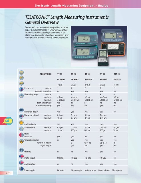
TESATRONIC ® <strong>Length</strong> <strong>Measuring</strong> <strong>Instruments</strong><br />
<strong>General</strong> <strong>Overview</strong><br />
Dedicated compact units having either an analog<br />
or a numerical display. Used in association<br />
with hand-held measuring instruments or on<br />
stationary devices for shop floor inspection and<br />
maintenance as well as in the measuring room.<br />
TESATRONIC TT 10 TT 20 TT 60 TT 80 TTA 20<br />
44.30008 44.90003 44.90004 44.90005 44.30003<br />
41239 87357 87358 27550 41234<br />
Probe input number 1 2 2 2 2<br />
automatic recognition no yes yes yes no<br />
<strong>Measuring</strong> range number 3 7 7 9 6<br />
minimum ± 5 μm ± 5 μm ± 5 μm ± 0.5 μm ± 3 μm<br />
maximum ± 500 μm ± 5000 μm ± 5000 μm ± 5000 μm ± 1000 μm<br />
zoom function (5x) yes no no no no<br />
automatic switching yes yes yes yes no<br />
Numerical display yes yes yes yes no<br />
Numerical interval minimum 0.1 μm 0.1 μm 0.1 μm 0.01 μm<br />
maximum 10 μm 0.1 μm 0.1 μm 0.01 μm<br />
Analog display yes yes yes yes yes<br />
Scale interval minimum 0.1 μm 0.2 μm 0.2 μm 0.02 μm 0.1 μm<br />
maximum 10 μm 200 μm 200 μm 200 μm 50 μm<br />
Metric /<br />
inch units yes yes yes yes yes<br />
Value classification no yes yes yes yes<br />
number of classes 3 up to 42 up to 42 3<br />
signal outputs yes yes yes yes<br />
Memory no no yes yes no<br />
Digital output RS-232 RS-232 RS -232 RS-232 no<br />
Analog output no no yes yes yes<br />
Power supply Batteries Mains adapter Mains adapter Mains adapter Mains power
✓<br />
DIN 32876<br />
Part 1<br />
2.6 x 2.25 in<br />
66 x 57 mm<br />
LC display field<br />
.354 x .177 in<br />
9 x 4.5 mm<br />
Response<br />
time of display<br />
≤ 100 ms.<br />
Hold time ≥ 100 ms.<br />
Zero drift*<br />
≤ ± 0.005% / °C<br />
Frequency limit of display<br />
with reference to signal<br />
input: 10 Hz<br />
Max. display<br />
error *: 2%<br />
± 1 numerical<br />
interval<br />
Opto-coupled<br />
RS-232<br />
compatible out-put<br />
3.5V to 4.5V,<br />
3 batteries type<br />
LRC 6, 1.5V, AA.<br />
Power consumption:<br />
≈ 7 mW / 3.5V<br />
Self-controlled voltage<br />
fluctuation<br />
Drive voltage<br />
of the probe: 0.7V<br />
Drive frequency:<br />
13 ± 0.65 kHz<br />
32 °F to 140 °F<br />
14 °F to 158 °F<br />
80%, with no<br />
condensation<br />
Protection IP42<br />
(IEC 60529)<br />
EN 50081-1,<br />
EN 50081-2,<br />
EN 50082-1, EN 50082-2<br />
3.75 x 6.7 x 2.7 in<br />
95 x 130 x 68 mm<br />
(W x D x H)<br />
1.08 lbs.<br />
(with batteries)<br />
Transport<br />
packing<br />
Identification<br />
number<br />
Declaration<br />
of conformity<br />
* with reference to 68 °F<br />
as well as a relative<br />
humidity of ≤ 50%.<br />
Electronic <strong>Length</strong> External <strong>Measuring</strong> Micrometers Equipment - Analog<br />
<strong>Measuring</strong> ranges and numerical interval<br />
Zoom<br />
Function<br />
TESATRONIC ® TT 10<br />
Electronic <strong>Length</strong> <strong>Measuring</strong> Instrument<br />
Pocket-sized, battery-operated electronic instrument for use on the move –<br />
Ideally suited for your measurement tasks on the surface plate, in the inspection<br />
room right next to the production floor or directly on the machine –<br />
Provides full portability where there’s no room for a cumbersome power cable.<br />
• Simple-to-use function keys used in conjunction with the combined<br />
analog/numerical indication providing easy reading.<br />
• LCD, pointerless display field for high repeatability and negligible hysteresis.<br />
• 3 measuring ranges, switchable manually or automatically depending on<br />
the size of the measured value.<br />
• Inch and metric conversion.<br />
• Additional signal amplification (5x) for easy display setting.<br />
• Quick zero-setting thanks to digital technology.<br />
• Signal input for one probe.<br />
• RS-232 compatible digital-output, opto-coupled.<br />
44.30008 41239 TESATRONIC TT 10<br />
Electronic measuring instrument with<br />
analog and numerical display;<br />
3 measuring ranges switchable from metric<br />
to inch; 1 probe input; RS-232 output.<br />
Provided with the following accessories :<br />
3 Batteries, 1.5V, type LRC 6, AA<br />
1 Visual template for value classification<br />
Optional accessories :<br />
47.68000 41299 1 Hand Switch<br />
47.68001 41300 1 Foot Switch<br />
47.61022* 41270 1 Output Cable – 10 pin<br />
47.61023* 41271 1 Cable to PC-AT RS-232 (9 pin male)<br />
47.61024* 41272 1 Cable to Printer RS-232 (925 pin male)<br />
47.61026* 26256 1 Cable to Printer (Seiko DPU201GS)<br />
(9 pin female)<br />
*Cables can be used on all TESATRONIC TTD <strong>Measuring</strong> Instru -<br />
ments equipped with the new opto-coupled RS-232 output card.<br />
Used<br />
for<br />
μm μm in in<br />
1 without measuring ± 500 10 ± 0.025 0.0005<br />
5x setting ± 100 2 ± 0.005 0.0001<br />
2 without measuring ± 50 1 ± 0.0025 0.00005<br />
5x setting ± 10 0.2 ± 0.0005 0.00001<br />
3 without measuring ± 5 0.1 ± 0.00025 0.000005<br />
L-5
L-6<br />
External Micrometers<br />
Electronic <strong>Length</strong> <strong>Measuring</strong> Equipment - Analog<br />
TESATRONIC ® TT 20, TT 60 and TT 80<br />
Electronic <strong>Length</strong> <strong>Measuring</strong> <strong>Instruments</strong><br />
Feature the most advanced technology – Provide functional reliability - Simpleto-use-Essential<br />
for shop floor inspection or in the measurement laboratory.<br />
<strong>TESATRONIC®</strong> TT 20<br />
Includes a combined analog/numerical display – 2 probe inputs<br />
for single, sum or difference measurements.<br />
• Large LC display for error-free reading.<br />
• Better repeatability and negligible hysteresis as the analog display<br />
has no mechanical pointer.<br />
• Choice between pointer or bar graph.<br />
• All measuring functions readable on the LC display.<br />
• 7 measuring ranges selectable manually or automatically according<br />
to the size of the measured value.<br />
• Direct conversion from metric to inch units.<br />
• Zeroing with just one touch button for each measuring channel.<br />
• Setting of tolerances through the keyboard.<br />
• 3 quality classes displayed through LEDs with control signal outputs.<br />
• Lockable display for step-by-step measurement routines.<br />
• Automatic recognition of the connected TESA probe with direct<br />
adaptation of the measurement signals to the right output (only for<br />
TESA probes made in 1997 or later).<br />
• Opto-coupled RS-232 output, bi-directional.<br />
• Power supply through mains adapter.<br />
<strong>TESATRONIC®</strong> TT 60<br />
Same features as model TESATRONIC TT 20, but with added functions<br />
that include:<br />
• Memory for retaining extreme values (max), (min), (max - min)<br />
as well as the mean value of (max) minus (min).<br />
• Dynamic measurement with acquisition of more than 100 single values/s.<br />
• Value classification with output signals through contact relay for 5, 10, 20<br />
and 40 good classes.<br />
• Remote signal processing using the analog output.<br />
TESATRONIC TT 20,<br />
TT 60 and TT 80<br />
✓<br />
DIN 32876<br />
Part 1<br />
5 x 2.5 in<br />
126 x 62 mm<br />
LC display<br />
4.3 in / 110 mm<br />
scale length<br />
50<br />
scale divisions<br />
.087 in / 2.2 mm<br />
6-digit display<br />
plus minus sign<br />
.5 x .25 in<br />
12.5 x 6.6 mm<br />
Zero drift<br />
and drift of the<br />
signal amplification*:<br />
≤ ± 0.005 % / °C<br />
No drift for the registered<br />
values<br />
output<br />
± 1 numerical<br />
interval<br />
RS-232<br />
opto-coupled<br />
6.5 Vdc up<br />
to 7.3 Vdc<br />
Consumption: 2 W<br />
Self-controlled voltage<br />
fluctuation<br />
Drive voltage of the<br />
probe: 3V<br />
32 °F to 140 °F<br />
14 °F to 158 °F<br />
80%, with no<br />
condensation<br />
Resistant<br />
plastic<br />
Protection: IP 54<br />
(IEC 60529) for<br />
the front face only.<br />
EN 50081-1,<br />
EN 50081-2,<br />
EN 50082-1, EN 50082-2<br />
10 x 9.25 x 4.75 in<br />
255 x 235 x 120 mm<br />
(B x T x H)<br />
2.4 lbs.<br />
* with reference to 20 °C<br />
as well as a relative<br />
humidity of ≤ 50%.
Transport<br />
packing<br />
Identification<br />
number<br />
Declaration<br />
of conformity<br />
Additional data on<br />
TESATRONIC TT 20<br />
Response time*<br />
of analog<br />
display with pointer and<br />
digital display: ≤ 80 ms<br />
Holding time of digital<br />
display: ≤ 10 ms<br />
Frequency<br />
limit for all<br />
displays with reference to<br />
the signal input: 12.5 Hz<br />
Limiting value<br />
for analog display<br />
as well as digital display<br />
and output*: 0.3%<br />
Drive frequency<br />
13 ± 0.65 kHz<br />
Additional data on<br />
TESATRONIC TT 60<br />
Response time*<br />
of analog<br />
display with pointer and<br />
digital display: ≤ 80 ms<br />
Holding time of digital<br />
display: 80 ms<br />
Response time of analog<br />
display with bar graphs,<br />
classification LEDs as<br />
well as analog output: ≤<br />
30 ms<br />
Response time**<br />
of the memory: ≤ 10 ms<br />
Frequency<br />
limit for all<br />
displays with reference to<br />
the signal input: 12.5 Hz<br />
Frequency limit with reference<br />
to the signal input:<br />
20 Hz for the analog<br />
output<br />
100 Hz for the memory<br />
Limiting value<br />
for analog<br />
display as well as digital<br />
display and output*:<br />
0.3%<br />
± 10 V<br />
Voltage range:<br />
± 2V up to<br />
* with reference to 68°F<br />
as well as a relative<br />
humidity of ≤ 50%<br />
** with reference to the<br />
analog output signal<br />
continued on next page<br />
Electronic <strong>Length</strong> External <strong>Measuring</strong> Micrometers Equipment - Analog<br />
44.90003 87357 TESATRONIC TT 20<br />
Electronic length measuring instrument with analog and<br />
numerical display; 7 measuring ranges switchable from metric<br />
to inch; value classification with 1 good class and signal output<br />
through contact relay; 2 probe inputs; RS-232 output.<br />
44.90004 87358 TESATRONIC TT 60<br />
Same features as model TT 20, but with added memory; dynamic<br />
measuring and signal output through contact relay for 5, 10, 20 or<br />
40 good classes; analog output.<br />
Delivery includes the following items :<br />
1 Mains adapter, 110 to 240 Vac, 50 to 60 Hz, 6.6 Vdc, 750 mA.<br />
1 Instruction manual.<br />
<strong>Measuring</strong> ranges with scale divisions or numerical intervals (TESATRONIC TT 20 and TT 60)<br />
μm μm μm in in in<br />
± 5000 0.1 200 ± 0.200 0.000005 0.01<br />
± 2000 0.1 100 ± 0.100 0.000005 0.005<br />
± 500 0.1 20 ± 0.02 0.000005 0.001<br />
± 200 0.1 10 ± 0.01 0.000005 0.0005<br />
± 50 0.1 2 ± 0.002 0.000005 0.0001<br />
± 20 0.1 1 ± 0.001 0.000005 0.00005<br />
± 5 0.1 0.2 ± 0.0002 0.000005 0.00001<br />
L-7
L-8<br />
External Micrometers<br />
Electronic <strong>Length</strong> <strong>Measuring</strong> Equipment - Analog<br />
<strong>TESATRONIC®</strong> TT 80<br />
High-resolution measuring instrument – Fitted with a combined analog/<br />
digital display – Provided with 2 probe inputs for single, sum and difference<br />
measurements.<br />
Same features as TESATRONIC TT 20 but with the following added functions:<br />
• 9 measuring ranges with numerical interval to 0.01 µm or 0.000001 in.<br />
• Memory for extreme values (max), (min) and (max) - (min) as well<br />
as mean of (max) and (min).<br />
• Dynamic measurement with acquisition of more than 10 single values/ s.<br />
• Value classification with output signals through contact relay for 5, 10, 20<br />
and 40 good classes.<br />
• Remote signal processing using the analog output.<br />
44.90005 27550 TESATRONIC TT 80<br />
High-resolution electronic length measuring instrument provided<br />
with a combined analog/digital display, 9 measuring ranges switchable<br />
from metric to inch, value classification with 1 good class and<br />
signals output through contact relay for 5, 10, 20 or 40 good<br />
classes, memory, dynamic measuring capability, 2 probe inputs,<br />
RS-232 interface as well as analog output.<br />
Delivered with the following accessories :<br />
1 Mains adapter - 110 to 240 Vac, 50 to 60 Hz, 6,6 Vdc, 750 mA<br />
1 Instruction manual.<br />
<strong>Measuring</strong> ranges with scale divisions or numerical intervals (TESATRONIC TT 80)<br />
μm μm μm in in in<br />
± 5000 0.01 200 ± 0.200 0.000001 0.01<br />
± 2000 0.01 100 ± 0.100 0.000001 0.005<br />
± 500 0.01 20 ± 0.02 0.000001 0.001<br />
± 200 0.01 10 ± 0.01 0.000001 0.0005<br />
± 50 0.01 2 ± 0.002 0.000001 0.0001<br />
± 20 0.01 1 ± 0.001 0.000001 0.00005<br />
± 5 0.01 0.2 ± 0.0002 0.000001 0.00001<br />
± 2 0.01 0.1 ± 0.0001 0.000001 0.000005<br />
± 0.5 0.01 0.02 ± 0.00002 0.000001 0.000001<br />
Output current: ≤ 2 mA.<br />
Permissible adjustment<br />
load: ≥ 5 kΩ.<br />
Residual ripple (with<br />
probe at zero point):<br />
≤ 1 mV<br />
Reference voltage level:<br />
analog earth 0V<br />
Drive frequency:<br />
13 ± 0.65 kHz<br />
Additional data on<br />
TESATRONIC TT 80<br />
Response time<br />
of the analog/<br />
digital display, classification<br />
LEDs as well as both<br />
digital and analog outputs:<br />
≤ 100 ms<br />
Holding time of digital<br />
display: 100 ms<br />
Response time **<br />
of the memory:<br />
≤ 100 ms<br />
Frequency<br />
limit for all<br />
types of display as well<br />
as the memory with<br />
reference to the signal<br />
input: 10 Hz<br />
Limiting<br />
values *:<br />
2% for analog display<br />
0.15 for digital display<br />
0.3% for analog output<br />
0.15% for digital output<br />
Voltage range:<br />
± 2V to ± 10V<br />
Output current:<br />
≤ 2 mA<br />
Permissible adjustment<br />
load: ≥ 5 kΩ<br />
Residual ripple (with<br />
probe at zero point):<br />
≤ 1 mV<br />
Reference voltage level:<br />
analog earth 0V<br />
Drive frequency:<br />
13 kHz ± 0.5%<br />
* with reference to 68°F<br />
as well as a relative<br />
humidity of ≤ 50%.<br />
** with reference to the<br />
analog output signal
✓<br />
DIN 32876<br />
Part 1<br />
≈ 100 mm<br />
scale length<br />
Response time:<br />
≤ 1 s (display),<br />
20 ms (analog output),<br />
10 ms (output signal of<br />
the classification)<br />
Zero drift*<br />
≤ ± 0.005% / °C<br />
Frequency limit *<br />
display: 1 Hz<br />
analog output:: 50 Hz<br />
classification: 30 Hz<br />
Limiting value*:<br />
1.5% (display),<br />
0.3% (analog output)<br />
Negligible<br />
(display) or 5%<br />
(classification signals)<br />
Voltage ± 1V,<br />
output current<br />
≤ 3 mA, perm. adjustment<br />
load ≥ 2 kΩ, residual<br />
ripple (at zero) ≤ 1 mV.<br />
Reference voltage level:<br />
analog earth (0V)<br />
230 or 115V<br />
- 10% to 20%,<br />
50 to 60 Hz<br />
Power consumption:<br />
≤ 20 VA<br />
Drive voltage<br />
of the probe: 1.5 Veff<br />
-10% to 5%<br />
Drive frequency:<br />
13 ± 0.65 kHz<br />
32 °F to 122 °F<br />
14 °F to 158 °F<br />
Protection IP40<br />
(IEC 60529)<br />
EN 50081-1,<br />
EN 50081-2,<br />
EN 50082-1, EN 50082-2<br />
258 x 190 x 158<br />
mm (W x D x H)<br />
7.5 lbs<br />
Transport<br />
packing<br />
Identification<br />
number<br />
Declaration<br />
of conformity<br />
* with reference to 68 °F<br />
as well as a relative<br />
humidity of ≤ 50%<br />
Electronic <strong>Length</strong> External <strong>Measuring</strong> Micrometers Equipment - Analog<br />
TESATRONIC ® TTA 20 Electronic<br />
<strong>Length</strong> <strong>Measuring</strong> Instrument<br />
Compact design with analog indication and value classification facility –<br />
Aluminum housing for harsh shop floor environment – Easy to handle.<br />
• Easy-to-read analog display with mirror strip to avoid parallax error.<br />
• 6 measuring ranges.<br />
• Metric / Inch conversion.<br />
• Easy display setting through electrical zero.<br />
• 2 probe inputs for single, sum or difference measurements.<br />
• 1 auxiliary signal input, e.g. for the correction values.<br />
• LEDs for signalling the relevant quality class with green for (Good),<br />
yellow for (Rework) and red for (Scrap).<br />
• Potentiometer for setting the limit deviations.<br />
• Polarity selector switch for the classification signals<br />
(internal and external dimensions).<br />
• Switch for locking or unlocking a displayed value.<br />
• Analog output for the connection of a remote displaying or scribing unit.<br />
44.30003 41234 TESATRONIC TTA 20<br />
Electronic length measuring instrument with analog display;<br />
6 measuring ranges; switchable from metric to inch; value<br />
classification with 1 good class and signal output through contact<br />
relay; 2 probe inputs.<br />
Supplied with one of the following cables depending on the country where goods are to be<br />
delivered (must be specified when ordering):<br />
Mains cable fitted with SEV connector, 3-wire cable type, 2 m long.<br />
Mains cable fitted with VDE connector, 3-wire cable type, 2 m long.<br />
Mains cable without connector, 3-wire cable type, 2 m long.<br />
Optional accessory<br />
44.60004 42743 15-pin connector for both analog output and classification<br />
signal output.<br />
<strong>Measuring</strong> ranges and scale intervals<br />
μm μm in in<br />
± 1000 50 ± 0.1 0.005<br />
± 300 10 ± 0.03 0.001<br />
± 100 5 ± 0.01 0.0005<br />
± 30 1 ± 0.003 0.0001<br />
± 10 0.5 ± 0.001 0.00005<br />
± 3 0.1 ± 0.0003 0.00001<br />
L-9
L-10<br />
External Micrometers<br />
Electronic <strong>Length</strong> <strong>Measuring</strong> Equipment - Analog<br />
TESA ® Portable Data Printer<br />
Intelligent printer designed for the inspection of finished parts or incoming<br />
goods – Provides SPC statistics and prints the results with graphic<br />
representations.<br />
TESA® PRINTER SPC<br />
Can be connected to TESA measuring instruments as well as those provided<br />
with a DIGIMATIC output – TESA PRINTER SPC is able to recognize the connected<br />
instrument and will execute an automatic configuration.<br />
(Normal) (Tolerance)<br />
Statistical Features<br />
Lower limit of size (LSL) – ●<br />
Upper limit of size (USL) – ●<br />
Tolerance<br />
Number of captured values<br />
– ●<br />
– sampling extent ● ●<br />
– < lowest size – ●<br />
– > highest size – ●<br />
– part out of tolerance given as % – ●<br />
Lowest list value ● ●<br />
Highest list value ● ●<br />
Value dispersion R ● ●<br />
Arithmetical mean x –<br />
● ●<br />
Standard deviation σn, σn-1 ● ●<br />
Process capability Cp, Cpk – ●<br />
Graphic Representations<br />
Position of each single value within<br />
the tolerance range (10 classes) – ●<br />
Histogram – ●<br />
LED Displays<br />
Sorting of each single value with<br />
green for Good, yellow for Rework – ●<br />
and red for Scrap<br />
• Memory capacity:<br />
9999 single values for one<br />
feature per sample.<br />
• Two function modes (Normal)<br />
and (Tolerance).<br />
• Limits of size quickly set on the<br />
display of the connected instrument<br />
with subsequent transfer to TESA<br />
PRINTER SPC.<br />
• Output of statistical values that<br />
are further printed with graphic<br />
representations.<br />
• Printing of report headings that will<br />
be completed by the operator.<br />
• Hard copies printed in a preferred<br />
language (English, German,<br />
French, Italian or Spanish).<br />
• Self-contained, battery-powered<br />
printer unit (optional).<br />
✓<br />
Matrix printer<br />
for printing on<br />
a thermal paper roll<br />
Paper width:<br />
4.3 in / 110 mm<br />
Print mode:<br />
40 signs / line<br />
RS-232<br />
Data inputs (9-pin male<br />
trapezoid input)<br />
DIGIMATIC<br />
(10-pin Ansley input)<br />
Connector<br />
with mini-jack<br />
for the remote trigger<br />
of data transfer<br />
Mains adapter<br />
230 Vac, 7.3 Vdc<br />
Optional accessory:<br />
6V battery pack,<br />
rechargeable<br />
122 °F to 104 °F<br />
14 °F to 140 °F<br />
Protection IP40<br />
(IEC 60529)<br />
EN 50081-1,<br />
EN 50081-2,<br />
EN 50082-1, EN 50082-2<br />
7 x 7 x 3.3 in<br />
180 x 180 x 84 mm<br />
(W x D x H)<br />
1.21 lbs.<br />
Transport<br />
packing<br />
Identification<br />
number<br />
Declaration<br />
of conformity
✓<br />
Matrix printer<br />
for printing on<br />
thermal paper<br />
2.25 in / 57 mm<br />
wide paper roll<br />
100 signs / s<br />
RS-232,<br />
bi-directional<br />
Connector<br />
with mini-jack for<br />
the remote trigger<br />
of data transfer<br />
Battery pack<br />
rechargeable<br />
via the mains adapter<br />
3.75 x 7 x 2.95 in<br />
195 x 175 x 75 mm<br />
(W x D x H)<br />
1.16 lbs.<br />
Transport<br />
packing<br />
Identification<br />
number<br />
Declaration<br />
of conformity<br />
Electronic <strong>Length</strong> External <strong>Measuring</strong> Micrometers Equipment - Analog<br />
599-1011-275-2<br />
64.90000 87359 TESA PRINTER SPC<br />
Printer with memory, SPC statistics and<br />
value classification; prints the results with<br />
graphical representations using the matrix<br />
printer provided with a 110 mm wide<br />
thermal paper roll; RS-232 interface.<br />
Delivery includes :<br />
1 Thermal paper roll, 110 mm wide.<br />
1 Mains adapter, 100 to 240 Vac,<br />
50 to 60 Hz, 6.6 Vdc, 750 mA.<br />
1 Mains cable US<br />
Technical Data:<br />
Capacity: 1999 measured values, one feature<br />
Matrix printer: Thermo-sensitive printing, 40 columns<br />
Power supply: Adapter 115VAC – 7.3 V DC<br />
Connectors:<br />
Working<br />
Mini-Jack for foot switch Sub-D 9 pm<br />
RS-232 input Ansley 10 pm input<br />
temperature range: 50° to 104° F/10° to 40 °C<br />
Dimensions: 7 in x 7 in x 3.3 in<br />
Weight:<br />
Electromagnetic<br />
1.2 lbs.<br />
compatibility as per:<br />
Optional accessories:<br />
EN50081-1, EN50081-2,<br />
EN50082-1, EN50082-2<br />
47.68035 27005 6V battery pack, rechargeable.<br />
599-1011-275-2<br />
Technical Data:<br />
87239 THE BASIC IMPACT PRINTER<br />
An economical printer for most new<br />
Brown & Sharpe tools with digital<br />
RS-232 output. It has no memory and<br />
no statistics. Powered by 110 VAC<br />
mains via an adapter/transformer with<br />
6 foot cord.<br />
Character Format: ASCII character set – 10 bits per<br />
character required, 7 or 8 of which are<br />
data bits<br />
Serial Interface: Selectable BAUD rates – 300, 600,<br />
1200, 2400, 4800, 9600, 19200<br />
Character Buffering: 1.5K<br />
Data Input Conn.: DB25 pin male receptacle<br />
Print Method:<br />
Character Matrix:<br />
6 x 8 dot matrix<br />
Impact dot matrix using Epson cash<br />
register ribbon<br />
Character Spacing: 24 column – 12.8 characters/inch<br />
32 column – 17 characters/inch<br />
40 column – 21 characters/inch<br />
Print Speed: 38 lines/min – 24 column,<br />
33 lines/min – 32/40 column<br />
Paper: Plain cash register paper –<br />
2.25"W x 2.75"O.D. x .44"I.D.<br />
64.90000<br />
L-11
L-12<br />
2<br />
11<br />
4<br />
5<br />
6<br />
7<br />
14<br />
8<br />
3<br />
5<br />
4<br />
11<br />
ø 17<br />
9<br />
10<br />
3<br />
1<br />
65<br />
12<br />
13<br />
External Micrometers<br />
Electronic <strong>Length</strong> <strong>Measuring</strong> Equipment - Analog<br />
TESA/Brown & Sharpe Electronic Probes<br />
Key components in any electronic linear mea sur ing system, TESA/Brown & Sharpe<br />
inductive probes detect the slightest vari a tion in size with absolute re li abil i ty.<br />
Whether fixed to a simple measuring sup port or integrated by the dozen into a<br />
com plex installation, they record dimensions with un vary ing pre ci sion. Rugged and<br />
vir tu al ly in sen si tive to tem per a ture vari a tion and elec tro mag net ic in ter fer ence,<br />
TESA/Brown & Sharpe inductive probes are com pact, can be used in any position<br />
and are easily brought into contact with the work to be checked.<br />
The pages that follow show the family of Brown & Sharpe/TESA standard halfbridge<br />
probes that are compatible with the amplifiers shown in the previous pages.<br />
Most of the probes shown here are also compatible with earlier Brown & Sharpe<br />
960, 990, and 1020 series amplifiers after normal recalibration/adjustment of the<br />
amplifier.<br />
All electronic probes are mounted on ball-bearings, except for miniature<br />
axial probes.<br />
• Ball-bearing measuring bolts are virtually insensitive to radial forces.<br />
• Probe guide system is efficiently protected against the penetration of solid and<br />
liquid contaminants by sealing rubber bellows. In normal conditions of use, nitrile<br />
elastomer rubber bellows are sufficient. For applications where the probes<br />
remain permanently in contact with cooling and lubricating agents, we would recommend<br />
the use of Viton rubber bellows.<br />
• Sealing bellows ensure full airtightness so that the measuring bolt is retracted by<br />
throwing off the air contained in the probe. This provides optimum protection of<br />
the guiding system as no mechanical means is used.<br />
• Electronic signal amplification with no use of any other mechanical<br />
component produces excellent repeatability and low hysteresis.<br />
• Maximum resolution: 0.01 µm.<br />
1 Mounting stem or probe housing<br />
2 Coil system<br />
3 Item mounted between both the ferromagnetic<br />
core and measuring bolt for<br />
the correction of the varying coefficients<br />
of thermal expansion<br />
4 Force compression spring<br />
5 Anti-rotation guidance<br />
6 Ball cage<br />
7 Setting element for limiting the bolt travel<br />
8 <strong>Measuring</strong> insert<br />
ø3,8<br />
1<br />
9<br />
10<br />
2<br />
12<br />
15<br />
8<br />
6<br />
Dimensions of<br />
the connector fitted<br />
to all TESA probes<br />
(minimum cable<br />
curve radius<br />
R = 15 mm).<br />
9 In-between tube being part of the<br />
coil system<br />
10 Ferromagnetic core<br />
11 Force spring stop<br />
12 Ball-bearing guide tube<br />
13 <strong>Measuring</strong> bolt<br />
14 Sealing rubber bellow<br />
15 Mechanical device for zero-setting<br />
Probe sensitivity<br />
All stated values are valid for<br />
the following reference conditions:<br />
• Drive voltage 3 V<br />
• Drive frequency 13 kHz<br />
• Adjustment load 2 kΩ<br />
All types 73.75<br />
Except for the<br />
probe series<br />
• GT 61 / 62 29.5<br />
• FMS 130 / 132 49.17<br />
mV / V / mm
Electronic <strong>Length</strong> External <strong>Measuring</strong> Micrometers Equipment - Analog<br />
Functioning Principle<br />
All TESA electronic probes (value sensors)<br />
work on the inductive principle with mechanical<br />
contact of the workpiece. They are fitted<br />
with a coil system inducing an alternating output<br />
voltage that depends on the the position<br />
of the ferromagnetic core. With a symmetric<br />
position, i.e. at electrical zero, no voltage is<br />
impressed. A move of the core, which may be<br />
attached to the measuring bolt while the measurand<br />
is being taken, leads to a change in<br />
the inductance. This change generates a signal<br />
that is amplified and rectified before being<br />
displayed and further output. Depending on<br />
the instrument type, the analog signal will be<br />
shown on a voltmeter or a numerical display<br />
after its digital transformation.<br />
Unambiguous assessment of the measurand<br />
(at bolt position) to the signal (displayed<br />
value) is the main characteristic of the analog<br />
value acquisition. One of its distinct advantages<br />
is that the value primarily displayed will<br />
be reproduced in the event of a power cut<br />
(switch-off or power failure).<br />
Standard TESA Half-Bridge<br />
Probes for use with TESA<br />
<strong>Measuring</strong> <strong>Instruments</strong><br />
These probes have two serial coils with<br />
middle output mounted side-by-side and<br />
energized by a sinusoidal alternation at 3 kHz.<br />
Both are linked together to a Wheatstone<br />
bridge over an additional half-bridge.<br />
X<br />
Rs<br />
Ua<br />
Uo<br />
-Ua<br />
Ua1,Fa1<br />
Rch1<br />
G1<br />
U=KxX<br />
Inductive probe related main parameters<br />
S travel<br />
U output current<br />
0 electrical zero<br />
L linearity range<br />
Lf linearity error<br />
The linearity range L, which is the range within<br />
which the max. perm. errors are contained, is<br />
equal to the measuring range. All max. perm.<br />
errors are limiting values given for linearity<br />
errors.<br />
TESA LVDT Probes<br />
These probes are based on a Linear Variable<br />
Differential Transformer (LVDT). They have<br />
three coils: one primary coil, which is is energized<br />
by a sinusoidal alternation at 5 kHz, and<br />
two secondary coils, connected in opposite<br />
phase, which generate the output current proportional<br />
to the measuring travel.<br />
Wiring plan of half-bridge probes Wiring plan of LVDT probes<br />
-S<br />
X<br />
Ua<br />
Rs Uo<br />
0<br />
+U<br />
L L<br />
-U<br />
Ua2,Fa2<br />
Rch2<br />
G2<br />
L f<br />
+S<br />
U=KxX<br />
L-13
L-14<br />
External Micrometers<br />
Electronic <strong>Length</strong> <strong>Measuring</strong> Equipment - Analog<br />
TESA/Brown & Sharpe Electronic Probes<br />
Quick Selection Tables<br />
8 mm Diameter Axial Probes with Ball-Bearing <strong>Measuring</strong> Bolt<br />
Standard probes<br />
Standard high-precision probes<br />
Standard long-travel probes<br />
Probes with extended measuring ranges<br />
<strong>General</strong> Information – Valid for all Types<br />
All of the characteristics given are valid for a ref er ence temperature of 20°C. These technical<br />
spec i fi ca tions are applicable to probes fitted with the standard contact point.<br />
Possible resolution: 0.01 µm.<br />
L = value measured from electrical zero in mm.<br />
Linearity Error: The linearity error noted in the above table shows the maximum value.<br />
The typical value can be half of the maximum value.<br />
<strong>Measuring</strong><br />
Range<br />
mm<br />
Travel<br />
mm<br />
599-982-10 GT 21 ± 2 4.3 axial mechanical Nitrile<br />
32.10904 GT 21 ± 2 4.3 axial mechanical Nitrile<br />
32.10924 GT 22 ± 2 4.3 radial by vacuum Nitrile<br />
32.30057 GTL 21 ± 2 4.3 axial mechanical Viton<br />
32.30056 GTL 22 ± 2 4.3 radial by vacuum Viton<br />
32.30036 GT 21HP ± 0.2 4.3 axial mechanical Nitrile<br />
32.30021 GT 22HP ± 0.2 4.3 radial by vacuum Nitrile<br />
32.30027 GT 27 ± 2 10.3 axial mechanical Viton<br />
32.30026 GT 28 ± 2 10.3 radial by vacuum Viton<br />
32.30041 GT 61 ± 5 10.3 axial mechanical Viton<br />
32.30042 GT 62 ± 5 10.3 radial by vacuum Viton<br />
Nominal sensitivity (half-bridge): GT62/61 – 29.5 m/V/mm (conditions: 3V, 13 kHz/2 kΩ);<br />
all other types - 73.75 mV/V/mm.<br />
Cable<br />
Exit<br />
Bolt<br />
Retraction<br />
Sealing<br />
Bellows
Electronic <strong>Length</strong> External <strong>Measuring</strong> Micrometers Equipment - Analog<br />
Moving Frequency<br />
Mass<br />
Limit Dismount<br />
(L in mm)<br />
N ** g<br />
Hz *** -able<br />
μm μm μm **** °C<br />
0.63 6 60 yes 0.01 0.02 0.2 + 3 . L 3 - 10 to 65 IP65<br />
0.63 6 60 yes 0.01 0.02 0.2 + 3 . L 3 - 10 to 65 IP65<br />
0.63 6 60 yes 0.01 0.02 0.2 + 3 . L 3 - 10 to 65 IP65<br />
0.63 6 60 yes 0.01 0.02 0.2 + 2.4 . L 2 - 10 to 65 IP65<br />
0.63 6 60 yes 0.01 0.02 0.2 + 2.4 . L 2 - 10 to 65 IP65<br />
0.63 6 60 no 0.01 0.01 0.07 + 0.4 . L 10 to 40 IP64<br />
0.63 6 60 no 0.01 0.01 0.07 + 0.4 . L 10 to 40 IP64<br />
0.63 8 60 yes 0.05 0.05 0.2 + 3 . L 3 - 10 to 65 IP65<br />
0.63 8 60 yes 0.05 0.05 0.2 + 3 . L 3 - 10 to 65 IP65<br />
0.9 8 60 yes 0.05 0.05 1 + 4 . L - 10 to 65 IP65<br />
0.9 8 60 yes 0.05 0.05 1 + 4 . L - 10 to 65 IP65<br />
** Nominal value of the measuring force at electrical zero, max. deviation ± 25%.<br />
*** Mechanical frequency limit valid for the final value of the measuring range with an amplitude of 10%.<br />
**** Max. perm. errors applicable to the linearity errors.<br />
IEC<br />
60529<br />
L-15
L-16<br />
External Micrometers<br />
Electronic <strong>Length</strong> <strong>Measuring</strong> Equipment - Analog<br />
8 mm Diameter Miniature Probes<br />
<strong>Measuring</strong> bolt hanging from diaphragm springs<br />
<strong>Measuring</strong> bolt guided on plain bearings<br />
Lever Type Probes<br />
Probes with Parallel Guiding<br />
Standard probes<br />
SWISS<br />
MADE<br />
32.30019<br />
PAT PEND<br />
SWISS<br />
MADE<br />
32.30049<br />
PAT PEND<br />
Probes (FMS protected)<br />
SWISS MADE<br />
Patented<br />
PROTECTED<br />
32.30001 GT 41 ± 0.3 0.7 axial none Nitrile<br />
32.30002 GT 42 ± 0.3 0.7 radial by vacuum Nitrile<br />
32.30035 GT 43 ± 1 2.1 axial mechanical Viton<br />
32.30017 GT 44 ± 1 2.1 radial by vacuum Viton<br />
599-988 GT 31 ± 0.3 0.7 angled<br />
32.10802 GT 31 ± 0.3 0.7 angled<br />
32.30019 FMS 100 ± 2 5.8 parallel by air pressure<br />
32.30028 FMS 102 ± 2 5.8 angled by air pressure<br />
32.30049 FMS 130 ± 2.9 5.8 parallel by air pressure<br />
32.30050 FMS 132 ± 2.9 5.8 angled by air pressure<br />
32.30037 FMS 100-P ± 2 5.8 parallel by air pressure<br />
32.30038 FMS 102-P ± 2 5.8 angled by air pressure<br />
* Position in relation to the measuring movement.<br />
<strong>Measuring</strong><br />
Range<br />
mm<br />
<strong>Measuring</strong><br />
Range<br />
mm<br />
<strong>Measuring</strong><br />
Range<br />
mm<br />
Travel<br />
mm<br />
Travel<br />
mm<br />
Travel<br />
mm<br />
Cable<br />
Exit<br />
Cable<br />
Exit<br />
Cable<br />
Exit *<br />
Bolt<br />
Retraction Sealing<br />
Bellows<br />
Insert<br />
Retraction<br />
(accessory)
Electronic <strong>Length</strong> External <strong>Measuring</strong> Micrometers Equipment - Analog<br />
Moving Frequency<br />
Mass<br />
Limit Dismount<br />
(L in mm)<br />
N ** g<br />
Hz *** -able<br />
μm μm μm **** °C<br />
0.63 2 60 no 0.01 0.01 0.2 + 5 . L 2 - 10 to 65 IP65<br />
0.63 2 60 no 0.01 0.01 0.2 + 5 . L 2 - 10 to 65 IP65<br />
0.4 2 60 no 0.1 0.15 0.2 + 5 . L 2 5 to 65 IP65<br />
0.4 2 60 no 0.1 0.15 0.2 + 5 . L 2 5 to 65 IP65<br />
Moving Frequency<br />
Mass<br />
Limit Dismount<br />
(L in mm)<br />
N ** g<br />
Hz *** -able<br />
μm μm μm **** °C<br />
0.1 12 25 no 0.1 0.25 0.2 + 50 . L 2 - 10 to 50 IP40<br />
0.1 12 25 no 0.1 0.25 0.2 + 50 . L 2 - 10 to 50 IP40<br />
Moving Frequency<br />
Mass<br />
Limit Dismount<br />
(L in mm)<br />
N ** g<br />
Hz *** -able<br />
μm μm μm **** °C<br />
2 110 25 yes 0.5 0.5 0.2 + 3 . L 3 - 10 to 65 IP50<br />
2 110 25 yes 0.5 0.5 0.2 + 3 . L 3 - 10 to 65 IP50<br />
2 110 25 yes 0.5 0.5 0.2 + 3 . L 3 - 10 to 65 IP50<br />
2 110 25 yes 0.5 0.5 0.2 + 3 . L 3 - 10 to 65 IP50<br />
2 110 25 yes 0.5 0.5 0.2 + 3 . L 3 - 10 to 65 IP54<br />
2 110 25 yes 0.5 0.5 0.2 + 3 . L 3 - 10 to 65 IP54<br />
** Nominal value of the measuring force at electrical zero, max. deviation ± 25%.<br />
*** Mechanical frequency limit valid for the final value of the measuring range with an amplitude of 10%.<br />
**** Max. perm. errors applicable to the linearity errors.<br />
IEC<br />
60529<br />
IEC<br />
60529<br />
IEC<br />
60529<br />
L-17
L-18<br />
External Micrometers<br />
Electronic <strong>Length</strong> <strong>Measuring</strong> Equipment - Analog<br />
LVDT Probes - <strong>General</strong> <strong>Overview</strong><br />
LVDT Probes with Parallel Guiding<br />
Standard probes<br />
SWISS<br />
MADE<br />
32.30019<br />
PAT PEND<br />
Probes (FMS protected)<br />
SWISS MADE<br />
Patented<br />
PROTECTED<br />
32.30033 FMS 100 LVDT ± 1.5 5.8 parallel by air pressure<br />
32.30034 FMS 102 LVDT ± 1.5 5.8 angled by air pressure<br />
32.30039 FMS 100-P LVDT ± 1.5 5.8 parallel by air pressure<br />
32.30040 FMS 102-P LVDT ± 1.5 5.8 angled by air pressure<br />
* Position in relation to the measuring movement.<br />
<strong>Measuring</strong><br />
Range<br />
mm<br />
mm<br />
Cable<br />
Exit *<br />
Insert<br />
Retraction<br />
(accessory)
Electronic <strong>Length</strong> External <strong>Measuring</strong> Micrometers Equipment - Analog<br />
Drive Voltage<br />
DriveFrequency<br />
Sensitivity<br />
N ** Adjustment Load<br />
mV / V / mm μm μm % *** °C<br />
2 3 V / 5 kHz / 100 kΩ 150 0.5 0.5 0.25 - 10 to 65 IP50<br />
2 3 V / 5 kHz / 100 kΩ 150 0.5 0.5 0.25 - 10 to 65 IP50<br />
2 3 V / 5 kHz / 100 kΩ 150 0.5 0.5 0.25 - 10 to 65 IP54<br />
2 3 V / 5 kHz / 100 kΩ 150 0.5 0.5 0.25 - 10 to 65 IP54<br />
** Nominal value of the measuring force at electrical zero, max. deviation ± 25%.<br />
*** Max. perm. errors given as % for linearity errors refer to each relevant measuring span (= difference between both first and last<br />
values of the measuring range). For max. perm. errors expressed in μm, see the information provided with each LVDT probe on<br />
the following pages.<br />
IEC<br />
60529<br />
L-19
L-20<br />
External Micrometers<br />
Electronic <strong>Length</strong> <strong>Measuring</strong> Equipment - Analog<br />
32.90119 32.90120 32.90121 32.90122 32.90123 32.90124<br />
ETAMIC (ZCB) GT 21 GT 22 GT 27 GT 28 FMS 100 FMS 102<br />
32.90143 32.90144 32.90145 32.90146<br />
MAHR GT 21 GT 22 GT 212 GT 222<br />
32.90149 32.90150<br />
MARPOSS GT 21 GT 22<br />
32.30059 GT 21 DC ± 2 0.63 axial<br />
32.30058 GT 22 DC ± 2 0.63 radial<br />
* Nominal value at electrical zero; max. deviation ± 25%. Valid for upright assembly position, with downward<br />
oriented measuring bolt, as well as for static measuring.<br />
Also available upon request :<br />
Compatibility of Brown & Sharpe<br />
TESA ® Probes with Electronic Equipment of<br />
other Manufacturers<br />
DC Axial Probes<br />
Provided with a direct current output for connection to a computer or any other<br />
unit fitted with an analog input.<br />
<strong>Measuring</strong><br />
Range / mm<br />
S32180358 S32180315 S32080302 S32080692 S32080721<br />
GT 27 DC ± 10V GT 28 DC GT 31 DC GT 41 DC GT 43 DC<br />
S32080569 S32020402 S32080729 S32080661 S32020214<br />
GT 44 DC ± 5V GT 61 DC GTL 222 DC ± 10V GT 272 DC GT 622 DC<br />
S32001487 S32080524 S32730497 S32080361<br />
FMS 100 DC FMS 102 DC FMS 132 DC ±10V FMS 100 DC-IP54<br />
Other existing versions: 2V / mm, 5V / mm and 10V / mm; max. output voltage 10V.<br />
N *<br />
Cable<br />
Exit<br />
✓<br />
DIN 32676<br />
Part 1<br />
For technical<br />
data, refer to<br />
each single standard<br />
probe<br />
GT 21 DC and GT 22 DC<br />
electronic probes<br />
✓<br />
DIN 32876<br />
Part 1<br />
See<br />
in the table<br />
Axial probes<br />
usable in any position<br />
8 mm dia.<br />
fixing shank<br />
Drive voltage:<br />
± 10 to ± 15V<br />
Consumption: 15 mA<br />
Adjustment load: > 1 kΩ<br />
Sensitivity: 1V / mm<br />
0.1 μm<br />
0.15 μm<br />
Max. perm.<br />
error of 15 μm<br />
relative to a 4 mm measuring<br />
span (measuring<br />
range ± 2 mm)<br />
Other technical<br />
data listed on<br />
pages L-12 and L-13<br />
Technical data sheets<br />
GT 21 DC: 32.00396<br />
GT 22 DC: 32.00397
✓<br />
DIN 32876<br />
Part 1<br />
See<br />
in the table<br />
Axial probes<br />
usable in any<br />
position<br />
8 mm dia.<br />
fixing shank<br />
Ball-bearing measuring<br />
bolt<br />
Distance from electrical<br />
zero of both stops is<br />
either adjustable (lower<br />
stop) or depending on<br />
the position of the latter<br />
(upper stop).<br />
Interchangeable measuring<br />
insert with a 3 mm<br />
dia. tungsten carbide<br />
ball tip. M2.5 thread<br />
Cable length: 2 m<br />
5-pin plug DIN 45322,<br />
LVDT without plug.<br />
Nickel-plated<br />
housing<br />
Stainless steel measuring<br />
bolt, hardened.<br />
Sealing bellows:<br />
resistant Nitrile<br />
or high-resistance Viton<br />
(elastomer)<br />
Moving mass:<br />
6 g<br />
Drive frequency13<br />
kHz<br />
(± 5%).<br />
Mechanical frequency<br />
limit: 60 Hz<br />
0.15 μm / °C,<br />
GTL 21 and<br />
GTL 211: 0.2 μm / °C<br />
20 ± 0.5 °C<br />
-10 °C to 65 °C<br />
GT 21 HP:<br />
10 °C to 40 °C<br />
80%<br />
Protection IP65<br />
(IEC 60529),<br />
GT 21 HP: IP64<br />
Transport<br />
packing<br />
Identification<br />
number<br />
Inspection<br />
report with a<br />
declaration of conformity<br />
Electronic <strong>Length</strong> External <strong>Measuring</strong> Micrometers Equipment - Analog<br />
Axial Probes<br />
Standard and LVDT Probes<br />
Universal probes for common but constraining applications.<br />
• 8 mm dia. probe housing. Can be clamped over its entire length.<br />
• <strong>Measuring</strong> bolt mounted on ball-bearings.<br />
• Both the probe housing and ball-bearing guide are separate from one<br />
another so that the measuring bolt moves easily even if the probe is not<br />
clamped appropriately.<br />
• Degree of protection IP65 according to IEC 60529.<br />
• Wide range of accessories including measuring inserts, spring sets, etc.<br />
GT 21 Probes with Axial Cable Exit<br />
Standard probes<br />
599-982-10 GT 21 ± 2 0.63 mechanical Nitrile<br />
32.10904 GT 21 ± 2 0.63 mechanical Nitrile<br />
32.10905 GT 21 ± 2 1.0 mechanical Nitrile<br />
32.10906 GT 21 ± 2 1.6 mechanical Nitrile<br />
32.10907 GT 21 ± 2 2.5 mechanical Nitrile<br />
32.10908 GT 21 ± 2 4.0 mechanical Nitrile<br />
High-Precision probes<br />
R 1,5 ø 8h6<br />
20,5<br />
-1,2 +3<br />
0<br />
<strong>Measuring</strong><br />
Range / mm<br />
Lower stop of the measuring<br />
bolt **, adjustable<br />
from… to ex-factory<br />
mm mm mm<br />
mm μm μm μm ***<br />
GT 21 - 2.2 0.1 - 1.2 4.3 0.01 0.02 0.2 + 3 . L 3 32.00249<br />
GTL 21 - 2.2 0.1 - 1.2 4.3 0.01 0.02 0.2 + 2.4 . L 2 32.00391<br />
GTL 211 - 2.2 0.1 - 1.2 4.3 0.01 0.02 0.2 + 2.4 . L 2 32.00435<br />
GT 21 HP - 2.2 0.1 - 1.2 4.3 0.01 0.01 0.07 + 0.4 . L 32.00264<br />
GT 21 LVDT - 2.2 0.1 - 1.7 4.3 0.15 0.15 4.5 **** 32.00228<br />
Technical<br />
Data Sheets<br />
** Distance from electrical zero. *** Max perm. errors applicable to the linearity errors (L in mm).<br />
**** With reference to the 3 mm measuring span (measuring range ± 1.5 mm).<br />
N *<br />
92<br />
61,5<br />
Bolt<br />
Retraction<br />
32.30036 GT 21 HP ± 0.2 0.63 mechanical Nitrile<br />
* Nominal value at electrical zero, max. ± 25%. Valid for upright assembly position,<br />
with downward oriented measuring bolt, as well as in static measuring.<br />
Sealing<br />
Bellows<br />
9<br />
GT21<br />
ø3<br />
99<br />
8<br />
GTL211<br />
L-21
L-22<br />
External Micrometers<br />
Electronic <strong>Length</strong> <strong>Measuring</strong> Equipment - Analog<br />
GT 22 Probes with Radial Cable Exit<br />
Standard probes<br />
<strong>Measuring</strong><br />
Range / mm<br />
599-982-18 GT 22 ± 2 0.63 by vacuum Nitrile<br />
32.10924 GT 22 ± 2 0.63 by vacuum Nitrile<br />
32.10921 GT 22 ± 2 0.16 by vacuum Nitrile<br />
32.10922 GT 22 ± 2 0.25 by vacuum Nitrile<br />
32.10923 GT 22 ± 2 0.4 by vacuum Nitrile<br />
32.10925 GT 22 ± 2 1.0 mechanical Nitrile<br />
32.10926 GT 22 ± 2 1.6 mechanical Nitrile<br />
32.10927 GT 22 ± 2 2.5 mechanical Nitrile<br />
32.10928 GT 22 ± 2 4.0 mechanical Nitrile<br />
32.30056 GTL 22 ± 2 0.63 by vacuum Nitrile<br />
* Nominal value at electrical zero, max. ± 25%. Valid for upright assembly position,<br />
with downward oriented measuring bolt, as well as in static measuring.<br />
GT22<br />
R 1,5<br />
20,5<br />
-1,2 +3<br />
0<br />
ø 8h6<br />
81,5<br />
N *<br />
Bolt<br />
Retraction<br />
Sealing<br />
Bellows<br />
. mm μm μm μm ***<br />
GT 22 - 2.2 0.1 - 1.2 4.3 0.01 0.02 0.2 + 3 . L3 32.00250<br />
GTL 22 - 2.2 0.1 - 1.2 4.3 0.01 0.02 0.2 + 2.4 . L2 32.00392<br />
GT 22 HP - 2.2 0.1 - 1.2 4.3 0.01 0.01 0.07 + 0.4 . Lower stop of the measuring<br />
bolt **, adjustable<br />
from… to<br />
mm mm<br />
ex-factory<br />
mm<br />
Technical<br />
Data Sheets<br />
L 32.00265<br />
** Distance from electrical zero *** Max perm. errors applicable to the linearity errors (L in mm).<br />
47<br />
ø 9,6<br />
19<br />
✓<br />
DIN 32876<br />
Part 1<br />
See<br />
in the table<br />
Axial probes<br />
usable in any<br />
position<br />
8 mm dia.<br />
fixing shank<br />
Ball-bearing measuring<br />
bolt<br />
Distance from electrical<br />
zero of both stops is<br />
either adjustable (lower<br />
stop) or depending on<br />
the position of the latter<br />
(upper stop)<br />
Interchangeable measuring<br />
insert with a 3 mm<br />
dia. tungsten carbide<br />
ball tip. M2.5 thread<br />
Cable length : 2 m<br />
5-pin plug DIN 45322,<br />
LVDT without plug<br />
Nickel-plated<br />
housing<br />
Stainless steel measuring<br />
bolt, hardened<br />
Sealing bellows:<br />
resistant Nitrile or<br />
high-resistance Viton<br />
(elastomer)<br />
Moving mass:<br />
6 g<br />
Drive frequency13<br />
kHz<br />
(± 5%).<br />
Mechanical frequency<br />
limit: 60 Hz<br />
0.15 μm / °C<br />
or 0.2 μm / °C<br />
for GTL 22<br />
20 ± 0.5 °C<br />
-10 °C to 65 °C.<br />
10 °C to 40 °C<br />
for GT 21 HP<br />
80%<br />
Protection IP65<br />
(IEC 60529),<br />
GT 21 HP: IP64<br />
Transport<br />
packing<br />
Identification<br />
number<br />
Inspection<br />
report with a<br />
declaration of conformity
✓<br />
DIN 32876<br />
Part 1<br />
See<br />
in the table<br />
Axial probes<br />
usable in any<br />
position<br />
8 mm dia.<br />
fixing shank<br />
Ball-bearing measuring<br />
bolt<br />
Distance from electrical<br />
zero of both stops is<br />
either adjustable (lower<br />
stop) or depending on<br />
the position of the latter<br />
(upper stop).<br />
Interchangeable measuring<br />
insert with a 3 mm<br />
dia. tungsten carbide<br />
ball tip. M2.5 thread<br />
Cable length : 2 m<br />
Standard probes with a<br />
5-pin plug DIN 45322,<br />
LVDT without plug.<br />
Nickel-plated<br />
housing<br />
Stainless steel measuring<br />
bolt, hardened.<br />
Viton rubber bellows:<br />
high-resistance elastomer<br />
Moving mass:<br />
6 g<br />
Drive frequency<br />
13 kHz (± 5%).<br />
Mechanical frequency<br />
limit: 60 Hz<br />
0.15 μm / °C<br />
20 ± 0.5 °C<br />
-10 °C to 65 °C<br />
80%<br />
Protection IP65<br />
(IEC 60529)<br />
Transport<br />
packing<br />
Identification<br />
number<br />
Inspection<br />
report with a<br />
declaration of conformity<br />
Electronic <strong>Length</strong> External <strong>Measuring</strong> Micrometers Equipment - Analog<br />
GT 27 Probes with Axial Cable Exit<br />
Standard probes<br />
Axial Probes with Long<br />
Retraction Travel<br />
Standard and LVDT Probes<br />
Universal inductive probes for common applications, especially with<br />
multigaging devices.<br />
• Long retraction travel to prevent the probe from being damaged.<br />
<strong>Measuring</strong><br />
Range / mm<br />
32.30027 GT 27 ± 2 0.63 mechanical Viton<br />
GT 28 Probes with Radial Cable Exit<br />
N *<br />
Bolt<br />
Retraction<br />
Sealing<br />
Bellows<br />
<strong>Measuring</strong><br />
Bolt Sealing<br />
Range / mm N * Retraction Bellows<br />
Standard probes<br />
32.30026 GT 28 ± 2 0.63 by vacuum Viton<br />
* Nominal value at electrical zero; max. deviation ± 25%.<br />
Valid for upright assembly position, with downward oriented measuring bolt, as well<br />
as in static measuring.<br />
1<br />
Lower stop of the measuring<br />
bolt **, adjustable<br />
from… to ex-factory<br />
mm mm mm<br />
mm μm μm μm ***<br />
Technical<br />
Data Sheets<br />
GT 27 - 2.2 0.1 - 1.2 10.3 0.05 0.05 0.2 + 3 . L3 32.00251<br />
GT 28 - 2.2 0.1 - 1.2 10.3 0.05 0.05 0.2 + 3 . L3 32.00252<br />
** Distance from electrical zero *** Max perm. errors applicable to the linearity errors (L in mm).<br />
L-23
L-24<br />
External Micrometers<br />
Electronic <strong>Length</strong> <strong>Measuring</strong> Equipment - Analog<br />
Axial Probes with<br />
Long <strong>Measuring</strong> Range<br />
Standard and LVDT Probes<br />
Probes designed for long measuring travels and low resolutions – Specially<br />
suited for multigaging systems.<br />
• Correction factor 2.5 times to obtain the true values.<br />
GT 61 Probes with Axial Cable Exit<br />
Standard probes<br />
<strong>Measuring</strong><br />
Range / mm<br />
32.30041 GT 61 ± 5 0.9 mechanical Viton<br />
GT 62 Probes with Radial Cable Exit<br />
N *<br />
Bolt<br />
Retraction Sealing<br />
Bellows<br />
<strong>Measuring</strong><br />
Range / mm N *<br />
Bolt<br />
Retraction<br />
Standard probes<br />
32.30042 GT 62 ± 5 0.9 by vacuum Viton<br />
Sealing<br />
Bellows<br />
* Nominal value at electrical zero; max. deviation ± 25%.<br />
Valid for upright assembly position, with downward oriented measuring bolt, as well<br />
as in static measuring.<br />
mm μm μm μm ***<br />
GT 61 - 5.1 5.2 10.3 0.05 0.05 1 + 4 . L 32.00294<br />
GT 611 - 5.1 5.2 10.3 0.05 0.05 1 + 4 . L 32.00437<br />
GT 62 - 5.1 5.2 10.3 0.05 0.05 1 + 4 . Bolt endstops **<br />
upper stop<br />
mm<br />
lower stop<br />
mm<br />
Technical<br />
Data Sheets<br />
L 32.00295<br />
GT 61 LVDT - 5.1 5.2 10.3 0.2 0.2 20 **** 32.00337<br />
GT 62 LVDT - 5.1 5.2 10.3 0.2 0.2 20 **** 32.00339<br />
** Distance from electrical zero. *** Max. perm. errors applicable to the linearity errors (L in mm).<br />
**** With reference to the 10 mm measuring span (measuring range ± 5 mm).<br />
✓<br />
DIN 32876<br />
Part 1<br />
See<br />
in the table<br />
Axial probes<br />
usable in any<br />
position<br />
Signal combinations<br />
with probes having<br />
a standard resolution<br />
may require your attention<br />
to needed correction<br />
8 mm dia.<br />
fixing shank<br />
Ball-bearing measuring<br />
bolt<br />
Both lower and upper<br />
bolt endstops are fixed<br />
Interchangeable measuring<br />
insert with a 3 mm<br />
dia. tungsten carbide<br />
ball tip. M2.5 thread.<br />
Cable length : 2 m<br />
5-pin plug DIN 45322.<br />
LVDT without plug<br />
Nickel-plated<br />
housing<br />
Stainless steel measuring<br />
bolt, hardened.<br />
Viton rubber bellows:<br />
high-resistance elastomer<br />
Moving mass:<br />
8 g<br />
Drive frequency<br />
13 kHz (± 5%).<br />
Mechanical frequency<br />
limit: 60 Hz<br />
0.09 μm / °C,<br />
GT 61 LVDT and<br />
GT 62 LVDT: 0.16 μm / °C<br />
20 ± 0.5 °C<br />
-10 °C to 65 °C<br />
80%<br />
Protection IP65<br />
(IEC 60529)<br />
Transport<br />
packing<br />
Identification<br />
number<br />
Inspection<br />
report with a<br />
declaration of conformity
✓<br />
DIN 32876<br />
Part 1<br />
See<br />
in the table<br />
Axial probes<br />
usable in any<br />
position<br />
8 mm dia.<br />
fixing shaft<br />
<strong>Measuring</strong> bolt guided<br />
on a plain bearing or<br />
hanging from diaphragms<br />
Both lower and upper<br />
bolt endstops are fixed<br />
GT 41 or GT 42 with a<br />
fixed measuring insert;<br />
spherical carbide measuring<br />
face, R 0.75 mm.<br />
GT 43 or GT 44 with a<br />
selectable measuring<br />
insert; spherical carbide<br />
measuring face, R 1 mm.<br />
M2 thread.<br />
Cable length: 2 m<br />
5-pin plug<br />
DIN 45322<br />
Nickel-plated<br />
fixing shank<br />
Resistant nitrile rubber<br />
bellow or Viton rubber<br />
bellow with high-resistance<br />
elastomer<br />
Moving mass:<br />
2 g<br />
Drive frequency<br />
13 kHz (± 5%)<br />
Mechanical frequency<br />
limit: 60 Hz<br />
0.1 μm / °C<br />
20 ± 0.5 °C<br />
GT 41 and GT 42:<br />
-10 °C to 65 °C,<br />
GT 43 and GT 44: 5 °C<br />
to 65 °C<br />
80%<br />
Protection IP65<br />
(IEC 60529)<br />
Transport<br />
packing<br />
Identification<br />
number<br />
Inspection<br />
report with a<br />
declaration of conformity<br />
Electronic <strong>Length</strong> External <strong>Measuring</strong> Micrometers Equipment - Analog<br />
Axial Miniature Probes<br />
Standard Probes<br />
Compact probes specially designed for use where there’s no room for longer<br />
probes – Possible assembly of measuring heads, etc.<br />
R 0,75<br />
-0,3<br />
4<br />
ø 8h6<br />
34<br />
47<br />
+0,4<br />
0 GT41<br />
GT 41 and GT 43 Probes with Axial Cable Exit<br />
<strong>Measuring</strong><br />
Range / mm<br />
<strong>Measuring</strong> bolt hanging from diaphragms<br />
599-989 GT 41 ± 0.3 0.63 none Nitrile<br />
<strong>Measuring</strong> bolt guided on a plain bearing<br />
32.30035 GT 43 ± 1 0.4 mechanical Viton<br />
N *<br />
Meas. Bolt<br />
Retraction Sealing<br />
Bellows<br />
mm μm μm μm ***<br />
GT 41 - 0.3 0.4 0.7 0.01 0.01 0.2 + 5 . L2 32.00258<br />
GT 43 - 1.05 1.05 2.1 0.1 0.15 0.2 + 5 . L2 Meas. bolt endstops: **<br />
lower stop<br />
mm<br />
upper stop<br />
mm<br />
Technical<br />
Data Sheets<br />
32.00260<br />
** Distance from electrical zero. *** Max. perm. errors applicable to the linearity errors (L in mm).<br />
L-25
L-26<br />
External Micrometers<br />
Electronic <strong>Length</strong> <strong>Measuring</strong> Equipment - Analog<br />
Axial Miniature Probes<br />
Standard Probes<br />
Compact probes specially designed for use where there’s no room for longer<br />
probes – Possible assembly of measuring heads, etc.<br />
GT 42 and GT 44 Probes with Radial Cable Exit<br />
<strong>Measuring</strong><br />
Range / mm<br />
<strong>Measuring</strong> bolt hanging from diaphragms<br />
599-989-1 GT 42 ± 0.3 0.63 by vacuum Nitrile<br />
<strong>Measuring</strong> bolt guided on a plain bearing<br />
599-989-2 GT 44 ± 1 0.4 by vacuum Viton<br />
* Nominal value at electrical zero; max. deviation ± 25%.<br />
Valid in upright assembly position, with downward oriented measuring bolt,<br />
as well as in static measuring.<br />
N *<br />
Meas. Bolt<br />
Retraction<br />
Sealing<br />
Bellows<br />
mm μm μm μm ***<br />
GT 42 - 0.3 0.4 0.7 0.01 0.01 0.2 + 5 . L2 32.00259<br />
GT 44 - 1.05 1.05 2.1 0.1 0.15 0.2 + 5 . L2 Meas. Bolt Endstops: **<br />
lower stop<br />
mm<br />
upper stop<br />
mm<br />
Technical<br />
Data Sheets<br />
32.00261<br />
** Distance from electrical zero. *** Max. perm. errors applicable to the linearity errors (L in mm).<br />
-1<br />
R 0,75<br />
-0,3<br />
5,6<br />
R1<br />
0<br />
0<br />
4<br />
ø 8h6<br />
33<br />
18,4<br />
ø8h6<br />
+1<br />
19<br />
36<br />
+0,4<br />
9<br />
5<br />
15<br />
29,5<br />
ø 9,6<br />
19<br />
GT42<br />
GT44<br />
✓<br />
DIN 32876<br />
Part 1<br />
See<br />
in the tables<br />
Axial probes<br />
usable in any<br />
position<br />
8 mm dia.<br />
fixing shaft<br />
<strong>Measuring</strong> bolt guided<br />
on a plain bearing or<br />
hanging from diaphragms<br />
Both lower and upper<br />
bolt endstops are fixed<br />
GT 41 or GT 42 with a<br />
fixed measuring insert;<br />
spherical carbide measuring<br />
face, R 0.75 mm.<br />
GT 43 or GT 44 with a<br />
selectable measuring<br />
insert; spherical carbide<br />
measuring face, R 1 mm.<br />
M2 thread.<br />
Cable length: 2 m<br />
5-pin plug<br />
DIN 45322<br />
Nickel-plated<br />
fixing shank<br />
Resistant nitrile rubber<br />
bellow or Viton rubber<br />
bellow with high-resistance<br />
elastomer<br />
Moving mass:<br />
2 g<br />
Drive frequency<br />
13 kHz (± 5%)<br />
Mechanical frequency<br />
limit: 60 Hz<br />
0.1 μm / °C<br />
20 ± 0.5 °C<br />
GT 41 and GT 42:<br />
-10 °C to 65 °C,<br />
GT 43 and GT 44: 5 °C<br />
to 65 °C<br />
80%<br />
Protection IP65<br />
(IEC 60529)<br />
Transport<br />
packing<br />
Identification<br />
number<br />
Inspection<br />
report with a<br />
declaration of conformity
✓<br />
DIN 32876<br />
Part 1<br />
± 0.3 mm<br />
Lever probe<br />
usable in any<br />
position<br />
2 dovetail<br />
attachments<br />
Both lower and upper<br />
bolt endstops are fixed<br />
Selectable measuring<br />
inserts, stainless steel<br />
shank fitted with a 2 mm<br />
carbide ball tip.<br />
For all other inserts, see<br />
under optional accessories<br />
on the next pages.<br />
Cable length: 2 m<br />
5-pin plug<br />
DIN 45322<br />
All-metal<br />
housing with<br />
matte-chromium finish<br />
Moving mass:<br />
12 g<br />
Drive frequency<br />
13 kHz (± 5 %)<br />
Mechanical frequency<br />
limit: 25 Hz<br />
20 ± 0.5 °C<br />
5 °C to 60 °C<br />
80%<br />
Protection IP40<br />
(IEC 60529)<br />
Equipped with<br />
one 2 mm dia.<br />
insert No. 32.60410,<br />
and one 8 mm dia. fixing<br />
shank No. 18.40105<br />
Transport<br />
packing<br />
Identification<br />
number<br />
Inspection<br />
report with a<br />
declaration of conformity<br />
Electronic <strong>Length</strong> External <strong>Measuring</strong> Micrometers Equipment - Analog<br />
TESA ® GT 31 Lever Type Probes<br />
Probes with inclinable insert for measuring in two directions – Ideally suited for use<br />
where probes with axial displacement of the measuring bolt are found awkward to use.<br />
• Ball-bearing balanced lever.<br />
• Interchangeable measuring insert fitted with a tungsten carbide ball tip<br />
and inclinable through 180°.<br />
• Automatic reversal of the probing direction while the direction of the<br />
indication remains unchanged.<br />
• Protected against shocks by 2 safety clutches.<br />
• One-piece housing provided with 2 dovetails.<br />
N *<br />
599-988 GT 31 ± 0.3 0.1 (Standard)<br />
32.10802 GT 31 ± 0.3 0.1 (Standard)<br />
32.10801 GT 31 ± 0.3 0.02<br />
32.10803 GT 31 ± 0.3 0.2<br />
A<br />
GT with special cable position<br />
<strong>Measuring</strong><br />
Range / mm<br />
599-988-18 GT 31 ± 0.3 0.1 (Standard)<br />
* Nominal value at electrical zero; max. deviation ± 25%.<br />
Valid with both probe housing and lever lying horizontally<br />
as well as in static measuring.<br />
ø 2<br />
L<br />
40<br />
18.40105<br />
mm μm μm μm **<br />
GT 31 0.7 0.1 0.25 0.2 + 50 . L 2 32.00266<br />
** Max perm. errors applicable to the linearity errors (L in mm).<br />
<strong>Measuring</strong> direction<br />
Dovetail Shank ø 8h6<br />
See page E-44.<br />
(90)<br />
50<br />
B<br />
Technical<br />
Data Sheets<br />
Note :<br />
If the measuring insert is lying parallel to the workpiece surface (Fig. A), the leverage<br />
is 1:1 so that the values as measured need not be corrected.<br />
Any other position (angle α in Fig. B) will change the effective length of the lever. Therefore, all read values<br />
must be corrected. With regard to this, see the instructions for use that came with your electronic probes.<br />
1,65<br />
20<br />
17<br />
<strong>Measuring</strong> direction<br />
α<br />
60°<br />
8,54<br />
6,4<br />
Shorten lever<br />
599-988-18<br />
Special Cable Position<br />
ø 1,5<br />
L-27
L-28<br />
External Micrometers<br />
Electronic <strong>Length</strong> <strong>Measuring</strong> Equipment - Analog<br />
L<br />
Accessories for GT 31 Probe Series<br />
L<br />
32.60414<br />
32.60410<br />
35.90003<br />
32.60410<br />
35.90003<br />
35.90007<br />
35.90001<br />
35.90014<br />
<strong>Measuring</strong> Inserts<br />
Ball Tip<br />
mm<br />
Standard one-piece probe shank<br />
32.60402 1 1 : 1 32<br />
32.60410 2 1 : 1 32<br />
32.60403 3 1 : 1 32<br />
Special two-piece probe shank<br />
Lever Amplification<br />
35.90002 1 1 : 1 32<br />
35.90003 2 1 : 1 32<br />
35.90004 3 1 : 1 32<br />
35.90005 4 1 : 1 32<br />
35.90006 1 1 : 2 72<br />
35.90007 2 1 : 2 72<br />
35.90008 3 1 : 2 72<br />
35.90009 4 1 : 2 72<br />
35.90010 1 1 : 3 112<br />
35.90001 2 1 : 3 112<br />
35.90011 3 1 : 3 112<br />
35.90012 4 1 : 3 112<br />
35.90013 1 1 : √ 10<br />
118.49<br />
35.90014 2 1 : √ 10<br />
118.49<br />
35.90015 3 1 : √ 10<br />
118.49<br />
35.90016 4 1 : √ 10<br />
118.49<br />
599-980-10 Dovetail Mounting Bracket<br />
For 599-986 and 599-988 Gage Heads<br />
32.40100 Fixing B rackets<br />
With dovetail and cylindrical bore<br />
<strong>Length</strong> L<br />
mm<br />
32.60414 Correction cable for the probe constant<br />
Used for the electrical correction to zero<br />
of the probe constant using the measuring insert<br />
fitted with a 1 mm dia. ball tip<br />
33<br />
ø 6,4<br />
6,3<br />
R9<br />
599-980-10<br />
32.40100<br />
✓<br />
Stainless steel<br />
insert holder<br />
with a tungsten carbide<br />
ball tip<br />
Transport<br />
packing<br />
✓<br />
Transport<br />
packing
✓<br />
DIN 32876<br />
Part 1<br />
See<br />
in the tables<br />
Probes with<br />
linear action<br />
usable in any position<br />
4 fixing<br />
threads M6<br />
Linear ball-bearing<br />
guiding with fixed stops<br />
Insert holder attachment<br />
with dovetail<br />
Cable length: 2 m<br />
Standard and protected<br />
probes with a 5-pin plug<br />
DIN 45322 integrating<br />
a setting element<br />
for the signals.<br />
LVDT probes have<br />
no plug and<br />
no adjust item.<br />
Hardened<br />
steel probe<br />
body, nickel-plated<br />
Moving mass:<br />
110 g<br />
Drive frequency<br />
13 kHz (± 5%).<br />
Not for LVDT probes.<br />
LVDT probes:<br />
Drive voltage: 3V<br />
Drive frequency: 5 kHz<br />
Adjustment load: 100 kΩ<br />
Sensitivity:<br />
150 mV / V / mm<br />
Mechanical<br />
frequency limit:<br />
25 Hz<br />
- 0.14 μm / °C.<br />
LVDT probes:<br />
0.15 μm / °C<br />
20 ± 0.5 °C<br />
-10 °C to 65 °C<br />
80%<br />
Protection IP50.<br />
Protected<br />
probes: IP54 (IEC<br />
60529)<br />
Transport<br />
packing<br />
Identification<br />
number<br />
Inspection<br />
report with a<br />
declaration of conformity<br />
Electronic <strong>Length</strong> External <strong>Measuring</strong> Micrometers Equipment - Analog<br />
Standard probes<br />
Probes with Parallel Guiding<br />
Standard, Protected and LVDT Probe<br />
Universal probes for multigaging devices. Lets you capture the values<br />
measured on machines and other fixtures for in-process inspection.<br />
• Long-life probes featuring a rugged compact design.<br />
• Modular construction to eliminate the need for many assembly components.<br />
• Ball-bearing probing movements.<br />
• Sense of the measuring force as well as probe retraction according<br />
to the accessory used.<br />
• Wide choice of measuring inserts and supports for optimum adaptation<br />
to your measuring work.<br />
FMS Probes with Parallel Cable Exit<br />
32.30019 FMS 100 ± 2 2 by air pressure<br />
32.30049 FMS 130 ± 2.9 2 by air pressure<br />
Probes (FMS protected)<br />
32.30037 FMS 100-P ± 2 2 by air pressure<br />
LVDT probes<br />
<strong>Measuring</strong><br />
Range<br />
mm<br />
32.30033 FMS 100 LVDT ± 1.5 2 by air pressure<br />
32.30039 FMS 100 P-LVDT ± 1.5 2 by air pressure<br />
* Nominal value at electrical zero; max. deviation ± 25%.Valid with probing movement<br />
exerted horizontally as well as in static measuring.<br />
5<br />
15 30 15 5<br />
70<br />
8<br />
M6<br />
38<br />
N *<br />
Insert<br />
Retraction<br />
(accessory)<br />
. mm μm μm μm***<br />
FMS 100 - 2.9 2.9 5.8 0.5 0.5 0.2 + 3 . L3 32.00253<br />
FMS 100-P - 2.9 2.9 5.8 0.5 0.5 0.2 + 3 . L3 32.00283<br />
FMS 130 - 2.9 2.9 5.8 0.5 0.5 0.2 + 3 . L3 32.00342<br />
FMS 130-P - 2.9 2.9 5.8 0.5 0.5 0.2 + 3 . L3 Mech. Stop: **<br />
lower upper<br />
Technical<br />
mm mm<br />
Data Sheets<br />
32.00344<br />
FMS 100 LVDT - 2.9 2.9 5.8 0.5 0.5 4.5 **** 32.00247<br />
FMS 100-P LVDT - 2.9 2.9 5.8 0.5 0.5 4.5 **** 32.00290<br />
** Distance from electrical zero *** Max. perm. errors applicable for linearity errors (L in mm)<br />
**** With reference to the 4 mm measuring span (measuring range ± 2 mm) or 5.8 mm (± 2.9 mm).<br />
L-29
L-30<br />
External Micrometers<br />
Electronic <strong>Length</strong> <strong>Measuring</strong> Equipment - Analog<br />
FMS Probes with Angled Cable Exit ✓<br />
<strong>Measuring</strong><br />
Insert<br />
Range<br />
Retraction<br />
mm<br />
N * (accessory)<br />
Standard probes<br />
32.30028 FMS 102 ± 2 2 air pressure<br />
32.30050 FMS 132 ± 2.9 2 air pressure<br />
Probes (FMS protected)<br />
32.30038 FMS 102-P ± 2 2 air pressure<br />
32.30052 FMS 132-P ± 2.9 2 air pressure<br />
LVDT probes<br />
32.30034 FMS 102 LVDT ± 1.5 2 air pressure<br />
32.30040 FMS 102 P-LVDT ± 1.5 2 air pressure<br />
* Nominal value at electrical zero; max. deviation ± 25%.Valid with probing<br />
movement exerted horizontally as well as in static measuring.<br />
Mechanical Stops **<br />
lower upper<br />
mm mm<br />
mm μm μm μm***<br />
FMS 102 - 2.9 2.9 5.8 0.5 0.5 0.2 + 3 . L 3 32.00254<br />
FMS 102-P - 2.9 2.9 5.8 0.5 0.5 0.2 + 3 . L 3 32.00289<br />
FMS 132 - 2.9 2.9 5.8 0.5 0.5 0.2 + 3 . L 3 32.00343<br />
FMS 132-P - 2.9 2.9 5.8 0.5 0.5 0.2 + 3 . L 3 32.00345<br />
FMS 102 LVDT - 2.9 2.9 5.8 0.5 0.5 4.5 **** 32.00248<br />
FMS 102-P LVDT - 2.9 2.9 5.8 0.5 0.5 4.5 **** 32.00291<br />
** Distance from electrical zero. *** Max. perm. errors applicable for linearity errors (L in mm)<br />
**** With reference to the 4 mm measuring span (measuring range ± 2 mm) or 5.8 mm (± 2.9 mm).<br />
5<br />
13<br />
15 30 15 5<br />
70<br />
M6<br />
8<br />
Technical<br />
Data Sheets<br />
DIN 32876<br />
Part 1<br />
See<br />
in the tables<br />
Probes with<br />
linear action<br />
usable in any position<br />
4 coupling<br />
threads M6<br />
Linear ball-bearing<br />
guiding with fixed stops<br />
Insert holder attachment<br />
with dovetail<br />
Cable length: 2 m<br />
Standard and FMS<br />
protected probes with<br />
a 5-pin plug DIN 45322<br />
integrating a calibration<br />
element for the signals.<br />
LVDT probes have<br />
no plug and no adjust<br />
item.<br />
Hardened<br />
steel probe,<br />
body, nickel-plated<br />
Moving mass:<br />
110 g<br />
Carrier frequency<br />
13 kHz (± 5%).<br />
Not for LVDT probes.<br />
LVDT probes:<br />
Drive voltage: 3V<br />
Drive frequency: 5 kHz<br />
Adjustment load: 100 kΩ<br />
Sensitivity:<br />
150 mV / V / mm<br />
Mechanical<br />
frequency limit:<br />
25 Hz<br />
- 0.15 μm / °C<br />
20 ± 0.5 °C<br />
-10 °C to 65 °C<br />
80%<br />
Protection IP50.<br />
Probes (FMS<br />
protected): IP54 (IEC<br />
60529)<br />
Transport<br />
packing<br />
Identification<br />
number<br />
Inspection<br />
report with a<br />
declaration of conformity
Electronic <strong>Length</strong> External <strong>Measuring</strong> Micrometers Equipment - Analog<br />
Example A<br />
• Activating the measuring insert<br />
towards the part to be inspected<br />
using the measuring force produced<br />
by the compression spring.<br />
• No insert retraction.<br />
Result:<br />
The measuring insert remains in<br />
position. Exchange of the part is<br />
made with mechanical contact<br />
with the probe under the measuring<br />
force.<br />
Example B<br />
• Activating the measuring insert<br />
towards the part to be inspected by<br />
using the measuring force produced<br />
by the compression spring.<br />
• Insert retraction by pneumatic<br />
pressure.<br />
Result:<br />
Exchange of the part is made with<br />
no mechanical contact with the<br />
probe.<br />
Example C<br />
• Activating the measuring insert<br />
towards the part to be inspected by<br />
air pressure using the measuring<br />
force produced by the compression<br />
spring.<br />
• Insert retraction by disabling the<br />
pneumatic pressure.<br />
Result:<br />
Exchange of the part is made with<br />
no mechanical contact with the probe<br />
providing absolute security through<br />
automatic retraction of the measuring<br />
insert in a pressureless condition.<br />
This configuration is also applied<br />
when there is no room on the left side<br />
for the pneumatic jack as shown in<br />
the example B.<br />
Configuration and Use of the<br />
TESA ® FMS Probes<br />
The following examples provide you with a number of possibilities to activate<br />
and retract the measuring insert during your measurement cycles.<br />
9<br />
4<br />
8<br />
6<br />
7<br />
1<br />
2<br />
5 10 8 9<br />
The force of the spring set (5) must<br />
be equivalent to the force of the<br />
auxiliary spring-loaded element (10).<br />
6<br />
5<br />
3<br />
5<br />
1 Fixed probe<br />
body<br />
2 Moving probe<br />
body<br />
3 <strong>Measuring</strong> element<br />
with fine<br />
adjustment<br />
4 Adjustable<br />
stop<br />
5 Spring set for the<br />
measuring force<br />
6 Fixing bores<br />
7 Holder for the<br />
measuring insert<br />
5 Spring set for<br />
the measuring<br />
force<br />
8 Pneumatic<br />
jack<br />
No. 32.6400<br />
9 Pressure<br />
connector<br />
5 Spring set for<br />
the measuring<br />
force<br />
8 Pneumatic<br />
jack<br />
No. 32.60440<br />
9 Pressure<br />
connector<br />
10 Auxiliary springloaded<br />
element<br />
No. 32.60445<br />
L-31
L-32<br />
External Micrometers<br />
Electronic <strong>Length</strong> <strong>Measuring</strong> Equipment - Analog<br />
Accessories for TESA ® FMS Probes<br />
Spring sets for the<br />
measuring force<br />
Spring sets<br />
Item 5 in the examples<br />
A to C<br />
Accessories for Pneumatic<br />
Activation for the Moving Probe Body<br />
32.60440 Pneumatic jack<br />
Activates the moving<br />
probe body. Force under a<br />
pressure of 4 bars: 11 N.<br />
Item 8 in both examples B and C.<br />
Insert Holder with Fine Adjustment<br />
N<br />
* 2.0 Nickel-plated<br />
32.60448 0.4 Red<br />
32.60449 0.63 Yellow<br />
32.60450 1.0 Green<br />
32.60451 1.6 Blue<br />
32.60452 2.5 Brown<br />
32.60453 4.0 Black<br />
* Supplied with FMS probes<br />
Auxiliary spring-loaded element<br />
Item 10 in the example C<br />
N<br />
32.60441 0.4 Red<br />
32.60442 0.63 Yellow<br />
32.60443 1.0 Green<br />
32.60444 1.6 Blue<br />
32.60445 2.0 Nickel-plated<br />
32.60446 2.5 Brown<br />
32.60447 4.0 Black<br />
Helps you to set the probe – Setting and locking screws remain accessible<br />
even with several probes mounted side by side.<br />
Mounting bores for the measuring insert<br />
mm<br />
Number<br />
Position mm<br />
26.30053 4 2 Horizontal 25<br />
26.30055 4 1 Vertical 25<br />
26.30052 6 2 Horizontal 25<br />
26.30054 6 1 Vertical 25<br />
26.30052/53<br />
ø<br />
26.30054/55<br />
✓<br />
All values given<br />
in the table for<br />
the measuring force are<br />
nominal values at the<br />
electrical zero; max.<br />
deviation ± 25 %. Valid<br />
for the probing movements<br />
exerted horizontally<br />
as well as in static<br />
measuring.<br />
Transport<br />
packing<br />
✓<br />
Width of the<br />
insert holder:<br />
12 mm<br />
Transport<br />
packing
✓<br />
Transport<br />
packing<br />
Centered inserts with a narrow flat<br />
measuring face<br />
26.60066 Carbide 12<br />
26.60068 Carbide 25<br />
Electronic <strong>Length</strong> External <strong>Measuring</strong> Micrometers Equipment - Analog<br />
Fixed insert holders<br />
With mounting bores for the inserts<br />
mm Number Position<br />
26.30042 4 2 Horizontal<br />
26.30043 4 1 Vertical<br />
26.30045 6 2 Horizontal<br />
26.30046 6 1 Vertical<br />
Inserts with a 4 mm diameter fixing shaft<br />
Lmm<br />
Inserts with a 2 mm dia. contact pin with<br />
spherical measuring face<br />
26.60073 Carbide 20<br />
26.60074 Carbide 40<br />
26.60075 Carbide 60<br />
4<br />
Lmm<br />
Off-centered inserts with a tungsten<br />
carbide ball tip<br />
mm Lmm<br />
26.60084 5 20<br />
26.60085 5 33<br />
26.60086 5 48<br />
Off-centered inserts with a narrow flat<br />
measuring face<br />
26.60067 Carbide 12<br />
26.60069 Carbide 25<br />
Lmm<br />
Inserts with a tungsten carbide ball tip<br />
mm Lmm<br />
26.60076 3 20<br />
26.60077 3 40<br />
26.60078 3 60<br />
Centered inserts with 2 cylindrical<br />
measuring faces<br />
26.60070 Carbide 20<br />
26.60071 Carbide 40<br />
26.60072 Carbide 60<br />
4<br />
Off-centered inserts with 2 cylindrical<br />
measuring faces<br />
26.60082 Carbide 40<br />
26.60083 Carbide 60<br />
26.30042/45<br />
26.30043/46<br />
Lmm<br />
Lmm<br />
L-33
L-34<br />
Inserts with a tungsten carbide ball tip<br />
07.60058 3<br />
07.60059 5<br />
07.60060 10<br />
External Micrometers<br />
Electronic <strong>Length</strong> <strong>Measuring</strong> Equipment - Analog<br />
Inserts with a 6 mm diameter fixing shaft<br />
mm<br />
TESATAST inserts with a tungsten carbide<br />
ball tip. M1.4 mounting thread<br />
Dmm Lmm<br />
18.60201 1 12.53<br />
18.60202 2 12.53<br />
18.60203 3 12.53<br />
18.60307 Key<br />
Insert with one flat and one spherical<br />
measuring face<br />
025589 Carbide 64<br />
Lmm<br />
Inserts with a barrel-shaped measuring<br />
face for cylindrical bores. Also serve<br />
for determining the position of internal<br />
threads<br />
mm<br />
For<br />
threads<br />
07.60066 2.2 M3 - M16<br />
07.60067 4.5 M6 - M48<br />
07.60068 9.7 M12 - M150<br />
Insert with a small cylindrical measuring<br />
face<br />
07.60082 Carbide 2<br />
2<br />
mm<br />
Universal insert holder provided with<br />
the following mounting facilities<br />
S26074372 1 x 4 mm dia.<br />
1 x 6 mm dia.<br />
2 x M1.4 threads<br />
2 x M2.5 threads<br />
Inserts with a tungsten carbide disc<br />
for grooves, nuts, centering shoulders<br />
etc.<br />
mm Emm<br />
07.60074 4.5 1<br />
07.60075 14 2<br />
07.60076 19 3<br />
Centered inserts with a small flat<br />
measuring face<br />
S26074380 Carbide 64<br />
Lmm<br />
Universal insert holder with 2 mounting<br />
threads<br />
07.60096 M1.4 and M2.5<br />
✓<br />
Transport<br />
packing
✓<br />
Transport<br />
packing<br />
✓<br />
Transport<br />
packing<br />
Standard inserts with a spherical<br />
measuring face<br />
35.10001 Steel 6<br />
35.10002 Carbide 6<br />
0,003<br />
6<br />
1,6<br />
7,5<br />
Inserts with a ball-bearing steel roller.<br />
Counternut for radial alignment<br />
35.60010 Steel<br />
Shape<br />
Cylindrical<br />
35.60011 Steel Domed<br />
7<br />
Electronic <strong>Length</strong> External <strong>Measuring</strong> Micrometers Equipment - Analog<br />
13<br />
Lmm<br />
Inserts with offset measuring faces<br />
Inserts with offset small<br />
and flat measuring faces<br />
26.30047 1<br />
26.30048 2<br />
26.30049 3<br />
26.30050 4<br />
26.30051 5<br />
Inserts with a spherical<br />
measuring face<br />
As shown in<br />
the drawing<br />
<strong>Measuring</strong> Inserts for TESA ® Axial<br />
Probes, Dial Gages and others<br />
Inserts fitted with a M2.5 Coupling Thread<br />
35.10101 Steel 5<br />
35.10102 Carbide 5<br />
6,5<br />
ø5<br />
0,3 0,5<br />
R5<br />
Insert with offset contact point (A).<br />
Counternut for radial alignment<br />
35.10401 Steel 6.5<br />
1,6<br />
6<br />
6<br />
Amm<br />
Rmm<br />
R1,5<br />
Inserts with 4 interchangeable steel pins,<br />
spherical measuring face R = 1.5 mm<br />
35.10201 Steel<br />
Lmm<br />
16, 26, 36, 46<br />
Insert with cylindrical measuring face.<br />
Counternut for radial alignment<br />
35.10502 Carbide<br />
ø1,5<br />
16/26/36/46<br />
9<br />
L-35
L-36<br />
5 6,5<br />
3,3<br />
1<br />
0,5<br />
5<br />
16<br />
Off-center insert with narrow<br />
measuring face.<br />
Counternut for radial alignment<br />
35.10602 Carbide 0.5<br />
Inserts with a flat measuring face<br />
35.10801 Steel 2.5<br />
35.10802 Carbide 2.5<br />
35.60022 Steel 3.4<br />
35.60023 Carbide 3.4<br />
External Micrometers<br />
Electronic <strong>Length</strong> <strong>Measuring</strong> Equipment - Analog<br />
Bmm<br />
Dmm<br />
Extensions for the measuring inserts<br />
35.40501 10<br />
35.40502 15<br />
35.40503 20<br />
35.40504 40<br />
Lmm<br />
<strong>Measuring</strong> Inserts with a M2 Coupling Thread<br />
for GT 43 and GT 44 Axial Miniature Probes<br />
Inserts with a spherical measuring face.<br />
M2 thread<br />
35.10204 Carbide R 1<br />
35.10103 Carbide R 5<br />
mm<br />
Insert with narrow measuring face.<br />
Adjustable parallelism. Counternut for<br />
radial alignment<br />
35.10702 Carbide 0.5<br />
Inserts with a spherical measuring face.<br />
R 5. M2 thread<br />
35.10202 Carbide 16<br />
35.10203 Carbide 26<br />
Bmm<br />
Lmm<br />
Extensions for measuring inserts with M2 thread<br />
35.40505 10<br />
35.40506 15<br />
Lmm<br />
Insert with flat measuring face.<br />
Adjustable parallelism. Counternut<br />
for radial alignment<br />
35.10902 Carbide 2.5<br />
Additional<br />
measuring<br />
inserts and<br />
extensions<br />
with M2.5<br />
coupling<br />
thread<br />
are listed<br />
in section E.<br />
mm<br />
Insert with a cylindrical measuring face.<br />
Counternut for radial alignment.<br />
M2 thread<br />
35.10503 Carbide
✓<br />
All values given<br />
in the table for the measuring<br />
force are nominal<br />
values at electrical zero;<br />
max. deviation ± 25 %.<br />
Valid for upright<br />
assembly position,<br />
with downward oriented<br />
measuring bolt,<br />
as well as in static<br />
measuring.<br />
Force related in-<br />
formation marked<br />
on the plastic sleeve<br />
Electronic <strong>Length</strong> External <strong>Measuring</strong> Micrometers Equipment - Analog<br />
GT 22 probe series<br />
32.60419 0.16<br />
32.60420 0.25<br />
32.60421 0.40<br />
Variety of Accessories<br />
for TESA ® Electronic Probes<br />
<strong>Measuring</strong> Force Spring Sets for Axial Probes<br />
N<br />
GT 21 and GT 22 probe series<br />
32.60422 1.0<br />
32.60423 1.6<br />
32.60424 2.5<br />
32.60425 4.0<br />
N<br />
GT 27 and GT 28 probe series<br />
32.60458 0.63<br />
32.60459 1.0<br />
32.60460 1.6<br />
32.60461 2.5<br />
GT 61 and GT 62 probe series<br />
32.60483 0.8<br />
32.60463 1.0<br />
32.60464 1.6<br />
32.60465 2.5<br />
Transport<br />
packing Spare Bellows for Axial Probes<br />
✓<br />
Nitrile: resistant<br />
synthetic rubber for<br />
normal use<br />
Viton: high-resistance<br />
synthetic rubber used<br />
where probes are constantly<br />
in contact<br />
with cooling and<br />
lubricating agents.<br />
Safety rings<br />
and washer<br />
Transport<br />
packing<br />
GT 21 and GT 22 probe series<br />
32.60468 Nitrile<br />
32.60470 Viton<br />
L-37
L-38<br />
External Micrometers<br />
Electronic <strong>Length</strong> <strong>Measuring</strong> Equipment - Analog<br />
Clamping Elements for Axial Probes<br />
Provided with 3 clamping faces – To make sure all the metrology properties<br />
of the guiding system will not be disturbed by the clamps.<br />
VKD Clamp Screw<br />
26.11013 M4<br />
VKE Clamp<br />
26.11014 8<br />
Clamp Collar<br />
mm<br />
Fastening points<br />
mm<br />
18.60401 5.6 or 9.5 diam. and<br />
dovetail<br />
VDE clamps with fastening sleeve<br />
and screw<br />
mm Lmm<br />
26.60048 8 28<br />
26.60049 8 37<br />
Manually Operated Devices for Retracting<br />
the <strong>Measuring</strong> Bolt<br />
35.40104 Mechanical<br />
retraction device<br />
consisting of:<br />
35.40101 1 Lift lever<br />
35.40102 1 Washer<br />
32.60401 Pneumatic<br />
retraction device<br />
Suited for the probe series<br />
GT 22 / 28 / 42 / 44 and 62<br />
consisting of:<br />
1 Manual vacuum pump<br />
35.40405 14 mm dia. air tube, 1 m.<br />
✓<br />
All dimensions<br />
shown in the<br />
drawing must be respected<br />
Transport<br />
packing<br />
✓<br />
Transport<br />
packing
Electronic <strong>Length</strong> External <strong>Measuring</strong> Micrometers Equipment - Analog<br />
Accessories for Axial Probes<br />
Cartridge Gage Head Mounting Bracket<br />
599-982-28 44757 8 mm<br />
Split Bushing<br />
35.60101 41155 8 mm to .375<br />
in O.D.<br />
Hose Connector<br />
599-982-30 25954 For Lateral Cable<br />
Gage Heads<br />
Vacuum Release Delay Valve<br />
599-982-27 44756 Used with<br />
Vacuum Release<br />
for controlling the<br />
return speed of<br />
the gaging point<br />
after retraction<br />
Tee Connector for Vacuum Release System<br />
599-982-26 44755 Used to connect<br />
two gage heads<br />
in a system<br />
Vacuum Hose<br />
35.40405 42735 Sold by the meter<br />
Extension Cable<br />
599-981-50 44745 10' length. Good<br />
with all B&S/TESA<br />
half-bridge gage<br />
heads. 5-Pin plug<br />
and socket.<br />
L-39
L-40<br />
External Micrometers<br />
Electronic <strong>Length</strong> <strong>Measuring</strong> Equipment - Analog<br />
MERCER Axial Probes - 490 and 491 Series<br />
For MERCER and TESA® Electronic Equipment<br />
Universal probes to suit common but constraining applications.<br />
• 8 mm body diameter that may be clamped over its entire length.<br />
• <strong>Measuring</strong> bolt mounted on a ball-bearing.<br />
• Probe body made in steel and nickel plated.<br />
• Degree of protection IP65 as per IEC 60529.<br />
• 490 series provided with a flexible axial cable exit with steel spring<br />
to prevent the cable from breaking.<br />
<strong>Measuring</strong><br />
Range<br />
mm<br />
490 Series with axial/radial cable exit**<br />
32.36490 32.30490 ± 1.5 0.63 mechanical Viton<br />
491 Series with radial cable exit<br />
32.36491 32.30491 ± 1.5 0.63 by vacuum Viton<br />
Accessories<br />
Lower stop of the measuring<br />
bolt***: adjustable<br />
from… to<br />
mm mm<br />
ex-factory<br />
mm<br />
mm μm % ****<br />
Technical<br />
DataSheets<br />
490 MERCER - 2 0 - 1.7 4.3 0.02 0.15 32.00450<br />
490 TESA - 2 0 - 1.7 4.3 0.02 0.2 32.00456<br />
491 MERCER - 2 0 - 1.7 4.3 0.02 0.15 32.00454<br />
491 TESA - 2 0 - 1.7 4.3 0.02 0.2 32.00457<br />
*** Distance from electrical zero.<br />
**** Max. perm. errors for linearity errors contained within the measuring span of 3 mm (measuring range ±1.5 mm).<br />
N *<br />
Page<br />
<strong>Measuring</strong> inserts L-35 and L-36<br />
Hand-operated retraction devices L-38<br />
491<br />
<strong>Measuring</strong><br />
Bolt<br />
Retraction<br />
490<br />
Sealing<br />
Bellows<br />
* Nominal value at electrical zero; max. deviation ± 0.15 N. Valid for upright assembly<br />
position, with downward oriented measuring bolt, as well as in static measuring.<br />
Also available on request: probes with measuring force of 0.4, 1.0, 1.6, 2.5 or 4 N.<br />
** With use of the right angle adaptor that came with the probe.<br />
✓<br />
DIN 32876<br />
Part 1<br />
See<br />
in the tables<br />
Axial probes<br />
usable in<br />
any position<br />
8 mm body<br />
diameter<br />
<strong>Measuring</strong> bolt mounted<br />
on a ball-bearing<br />
Adjustable distance<br />
between both the lower<br />
stop and electrical zero.<br />
Interchangeable measuring<br />
insert with M2.5<br />
thread. 3 mm dia. carbide<br />
ball tip.<br />
Cable length: 2 m<br />
Plug type: DIN 45322<br />
Nickel plated<br />
body<br />
Steel measuring bolt,<br />
hardened.<br />
Viton rubber bellow<br />
with high-resistance<br />
elastomer<br />
Moving mass:<br />
4 g<br />
Force increase:<br />
0.2 N/mm<br />
Mechanical<br />
frequency<br />
limit: 60 Hz<br />
0.2 μm / °C<br />
- 10 °C to 65 °C<br />
-20 °C to 65 °C<br />
IP65<br />
(IEC 60529)<br />
Transport<br />
packing<br />
Identification<br />
number
✓<br />
DIN 32876<br />
Part 1<br />
See<br />
in the tables<br />
Axial probes<br />
usable in<br />
any position<br />
8 mm body<br />
diameter<br />
<strong>Measuring</strong> bolt mounted<br />
on a ball-bearing<br />
Adjustable distance<br />
between both the lower<br />
stop and electrical zero.<br />
Interchangeable measuring<br />
insert with a M2.5<br />
thread. 3 mm dia.<br />
tungsten carbide ball tip.<br />
Cable length: 2 m<br />
Plug type: DIN 45322<br />
Steel body,<br />
hardened and<br />
hard chrome plated.<br />
Stainless steel measuring<br />
bolt, hardened.<br />
Rubber bellows:<br />
resistant nitrile or Viton<br />
with high-resistance<br />
elastomer<br />
Moving mass:<br />
3.1g (410 series)<br />
or 3.2 g (411 series)<br />
Force increase:<br />
0.15 N/mm<br />
Mechanical<br />
frequency<br />
limit: 60 Hz<br />
0.025 μm / °C<br />
0 °C to 65 °C<br />
-40 °C to 65 °C<br />
IP62 (410 series)<br />
IP 65 (411 series) as per<br />
IEC 60529<br />
Transport<br />
packing<br />
Identification<br />
number<br />
Electronic <strong>Length</strong> External <strong>Measuring</strong> Micrometers Equipment - Analog<br />
MERCER Axial Probes with Short Body<br />
<strong>Length</strong> - 410 and 411 Series<br />
For MERCER and TESA® Electronic Equipment<br />
Universal probes for common but constraining applications.<br />
• 8 mm body diameter that may be clamped over its entire length.<br />
• <strong>Measuring</strong> bolt mounted in a ball-bearing.<br />
• Hardened steel body, hard chrome plated.<br />
• Degree of protection IP62 (410 series) or IP65 (411 series) as per<br />
IEC 60529.<br />
• 490 series provided with a flexible axial cable exit with steel spring<br />
to prevent the cable from breaking.<br />
<strong>Measuring</strong><br />
<strong>Measuring</strong><br />
Range<br />
Bolt<br />
mm<br />
410 Series with axial/radial cable exit**<br />
N * Retraction<br />
96410010 96410012 ± 1 0.6 mechanical Nitrile<br />
Sealing<br />
Bellow<br />
411 Series with radial cable exit<br />
96411011 96411014 ± 1 0.6 by vacuum Viton<br />
Accessories<br />
<strong>Measuring</strong> inserts<br />
Page<br />
L-35 and L-36<br />
Hand-operated retraction devices L-38<br />
* Nominal value at electrical zero; max. deviation ± 0.15 N. Valid for upright assembly<br />
position, with downward oriented measuring bolt, as well as in static measuring.<br />
Also available on request: 410 probe series with measuring force of 0.1 or 1.6 N.<br />
** With use of the right angle adaptor that came with the probe.<br />
410<br />
411<br />
Lower stop of the measuring<br />
bolt***: adjustable<br />
from… to<br />
mm mm<br />
ex-factory<br />
mm<br />
mm μm % ****<br />
Technical<br />
Data Sheets<br />
410 MERCER - 1.2 0 - 1.08 2.5 0.1 0.2 F96410010<br />
410 TESA - 1.2 0 - 1.08 2.5 0.1 0.2 F96410012<br />
411 MERCER - 1.2 0 - 1.08 2.5 0.1 0.2 F96411011<br />
411 TESA - 1.2 0 - 1.08 2.5 0.1 0.2 F96411014<br />
*** Distance from electrical zero.<br />
**** Max. perm. errors for linearity errors within a 2 mm measuring span (measuring range ± 1 mm).<br />
L-41
L-42<br />
External Micrometers<br />
Electronic <strong>Length</strong> <strong>Measuring</strong> Equipment - Analog<br />
MERCER Axial Probes with Long Travel -<br />
510, 500 and 501 Series<br />
For MERCER and TESA® Electronic Equipment<br />
Universal probes for multigaging dedicated devices used in standard<br />
applications.<br />
• Long travel to ensure optimum protection of the probe.<br />
<strong>Measuring</strong><br />
Range<br />
mm<br />
510 Series with axial/radial cable exit**<br />
96510017 96510013 ± 2.5 1.3 ± 0.3 mechanical Viton<br />
500 Series with axial/radial cable exit**<br />
96500010 96500015 ± 5 1.5 ± 0.3 mechanical Viton<br />
501 Series with radial cable exit<br />
96500013 96500025 ± 5 0.23 ± 0.06 by vacuum Viton<br />
Accessories<br />
17 / 26.5<br />
49.7 / 98.25<br />
ø7.98<br />
ø8.00<br />
26.5 98.4 24.4<br />
ø7.98<br />
ø8.00<br />
Lower stop of the measuring<br />
bolt***: adjustable<br />
from… to<br />
mm mm<br />
ex-factory<br />
mm<br />
mm μm % ****<br />
Technical<br />
Data Sheets<br />
510 MERCER - 2.8 0 - 2.6 5.3 0.1 0.2 F96510017<br />
510 TESA - 2.8 0 - 2.6 5.3 0.1 0.2 F96510013<br />
500 MERCER – – - 5.25 11.5 0.1 0.2 F96500010<br />
500 TESA – – - 5.25 11.5 0.1 0.2 F96500015<br />
501 MERCER – – - 5.25 11.5 0.1 0.2 F96500013<br />
501 TESA – – - 5.25 11.5 0.1 0.2 F96500025<br />
*** Distance from electrical zero.<br />
**** Max. perm. errors for linearity errors contained within the 5 mm or 10 mm measuring span (measuring<br />
range ± 2.5 mm or ± 5 mm, respectively).<br />
N *<br />
Page<br />
<strong>Measuring</strong> inserts L-35 and L-36<br />
Hand-operated retraction devices L-38<br />
33 / 31<br />
510/500<br />
501<br />
ø10<br />
<strong>Measuring</strong><br />
Bolt<br />
Retraction Sealing<br />
Bellows<br />
* Nominal value at electrical zero; max. deviation ± 0.15 N. Valid for upright assembly<br />
position, with downward oriented measuring bolt, as well as in static measuring.<br />
** With use of the right angle adaptor that came with the probe.<br />
30.5<br />
18 / 15.6<br />
30<br />
✓<br />
DIN 32876<br />
Part 1<br />
See<br />
in the tables<br />
Axial probes<br />
usable in<br />
any position<br />
8 mm body<br />
diameter<br />
Ball-bearing meas. bolt<br />
Distance between both<br />
stops and electrical zero:<br />
adjustable for 510 series<br />
(lower stop only) or fixed<br />
for 500 and 501 series.<br />
Interchangeable measuring<br />
insert with a M2.5<br />
thread. 3 mm dia.<br />
tungsten carbide ball tip.<br />
Cable length: 2 m<br />
Plug type: DIN 45322<br />
Steel body,<br />
hardened and<br />
hard chrome plated.<br />
Hardened steel<br />
measuring bolt<br />
Viton rubber bellows<br />
with high-resistance<br />
elastomer<br />
Moving<br />
mass:<br />
3.8 g (MERCER 510)<br />
4.2 g (TESA 510)<br />
6.8 g (500 and 501)<br />
Force<br />
increase:<br />
0.4 N/mm (510 series)<br />
0.15 N/mm (500 series)<br />
0.03 N/mm (501 series)<br />
Mechanical<br />
frequency<br />
limit:<br />
60 Hz (510 series)<br />
45 Hz (500/501 series)<br />
0.025 μm / °C<br />
0 °C to 60 °C<br />
-40 °C to 60 °C<br />
IP62 (510/500<br />
series) or IP 65 (501<br />
series) as per IEC 60529<br />
Transport<br />
packing<br />
Identification<br />
number
✓<br />
DIN 32876<br />
Part 1<br />
See<br />
in the tables<br />
Axial probes<br />
usable in<br />
any position<br />
8 mm body<br />
diameter<br />
8 mm diameter<br />
cylindrical body 0 /-20 μm,<br />
8 mm long for coupling<br />
the measuring bolt.<br />
Cable length: 2 m<br />
Plug type: DIN 45322<br />
Steel body,<br />
hardened and<br />
hard chrome plated<br />
Moving mass:<br />
3.4 g<br />
0 °C to 60 °C<br />
-40 °C to 60 °C<br />
IP40<br />
(IEC 60529)<br />
Transport<br />
packing<br />
Identification<br />
number<br />
Electronic <strong>Length</strong> External <strong>Measuring</strong> Micrometers Equipment - Analog<br />
MERCER Axial Probes without guidance<br />
of the measuring bolt - 460 Series<br />
For MERCER and TESA® Electronic Equipment<br />
Specially designed for assembly on measuring instruments and other gaging<br />
devices – Suitable for capturing any displacement on machines or fixtures<br />
used for in-process inspection.<br />
• Open type transducers with measuring bolt mechanically coupled.<br />
• 8 mm body diameter that may be clamped over its entire length.<br />
Made in hardened steel and hard chrome plated.<br />
• Flexible axial cable exit with steel spring to prevent the cable from breaking.<br />
<strong>Measuring</strong><br />
Range / mm<br />
460 Series with axial/radial cable exit*<br />
96460011 96460014 ± 1.5 none<br />
* With use of the right angle adaptor that came with the probe.<br />
ø7.98<br />
ø8.00<br />
460<br />
8.1<br />
7.9<br />
28 26<br />
ø7.98<br />
ø8.00<br />
Sealing Bellows<br />
% *<br />
Technical<br />
Data Sheets<br />
460 MERCER 0.15 F96460011<br />
460 TESA 0.15 F96460014<br />
* Max. perm. errors for linearity errors contained within the<br />
measuring span of 3 mm (measuring range ± 1.5 mm).<br />
11.7<br />
L-43
L-44<br />
External Micrometers<br />
Electronic <strong>Length</strong> <strong>Measuring</strong> Equipment - Analog<br />
MERCER Axial Probes with Air Activation<br />
of the <strong>Measuring</strong> Bolt - 492 Series<br />
For MERCER and TESA® Electronic Equipment<br />
Designed for use in measuring devices providing fully or half-assisted<br />
inspection routines.<br />
• 8 mm body diameter that may be clamped over its entire length.<br />
Steel and nickel plated.<br />
492 Series with radial cable exit<br />
32.36492 32.30492 ± 1.5 0.2 ▼ ▲ none<br />
Accessories<br />
<strong>Measuring</strong><br />
Bolt<br />
mm<br />
Lower stop of the<br />
measuring bolt **<br />
mm<br />
mm μm % ***<br />
Technical<br />
DataSheets<br />
492 MERCER - 1.7 ± 0.1 4.3 0.02 0.15 32.00455<br />
492 TESA - 1.7 ± 0.1 4.3 0.02 0.2 32.00458<br />
** Fixed distance from electrical zero.<br />
*** Max. perm. errors for linearity errors contained within the 3 mm measuring span (measuring range ± 1.5 mm).<br />
N *<br />
Page<br />
<strong>Measuring</strong> inserts L-35 and L-36<br />
* Nominal value at electrical zero; max. deviation ± 25%. Valid at a pressure of<br />
0.25 bar with use of the probe in upright assembly position, with downward<br />
oriented measuring insert, as well as in static measuring.<br />
▼ Downward movement of the measuring bolt activated by air pressure.<br />
▲ Upward movement of the measuring bolt activated under the spring force only.<br />
492<br />
<strong>Measuring</strong><br />
Bolt<br />
Activation Sealing<br />
Bellows<br />
✓<br />
DIN 32876<br />
Part 1<br />
See<br />
in the tables<br />
Axial probes<br />
usable in<br />
any position<br />
8 mm body<br />
diameter<br />
<strong>Measuring</strong> bolt mounted<br />
on a ball-bearing<br />
Distance between both<br />
stops and the electrical<br />
zero is fixed<br />
Interchangeable insert<br />
with a 3 mm dia. carbide<br />
ball tip. M2.5 thread.<br />
Cable length: 2 m<br />
Plug type: DIN 45322<br />
Steel body,<br />
nickel plated.<br />
<strong>Measuring</strong> bolt in<br />
hardened steel<br />
Moving mass:<br />
4 g<br />
Force<br />
increase:<br />
0.045 N/mm<br />
Mechanical<br />
frequency<br />
limit: 60 Hz<br />
Air pressure:<br />
0.25 bar (nominal)<br />
6 bar (maximum)<br />
Air filter capacity:<br />
✓<br />
DIN 32876<br />
Part 1<br />
See<br />
in the tables<br />
Axial probes<br />
usable in<br />
any position<br />
8 mm body<br />
diameter<br />
Ball-bearing measuring<br />
bolt<br />
Distance between both<br />
stops and electrical zero<br />
is either adjustable (lower<br />
stop only, 160 series) or<br />
fixed (451series).<br />
Interchangeable insert<br />
M2 thread (160 series)<br />
M2.5 thread (430 and 451<br />
series)<br />
3 mm dia. tungsten<br />
carbide ball tip.<br />
Cable length: 2 m<br />
Plug type: DIN 45322<br />
Steel body,<br />
hardened and<br />
chrome plated.<br />
<strong>Measuring</strong> bolt in<br />
stainless steel, hardened.<br />
Rubber bellows:<br />
resistant nitrile or Viton<br />
with high-resistance<br />
elastomer<br />
Mobile mass:<br />
2.5 g (160 series)<br />
1.9 g (430 series)<br />
3.0 g (451series)<br />
Force<br />
increase:<br />
0.3 N/mm (160 series)<br />
0.25 N/mm (430 series)<br />
0.15 N/mm (451 series)<br />
Mechanical<br />
frequency<br />
limit: 60 Hz<br />
0.025 μm / °C<br />
0 °C to 60 °C<br />
-40 °C to 60 °C<br />
IP62<br />
(IEC 60529)<br />
Transport<br />
packing<br />
Identification<br />
number<br />
Electronic <strong>Length</strong> External <strong>Measuring</strong> Micrometers Equipment - Analog<br />
<strong>Measuring</strong><br />
Range<br />
mm<br />
N *<br />
160 Series - Probes with short body length and axial cable exit<br />
96160011 96160013 ± 1 0.6 ± 0.15 mechanical Viton<br />
430 Series - Miniature probes with axial cable exit<br />
96430028 96430029 ± 0.5 0.75 ± 0.2 mechanical Nitrile<br />
451 Series - Miniature probes with radial cable exit<br />
96441015 96441041 ± 0.5 0.6 ± 0.15 mechanical Nitrile<br />
Accessories<br />
MERCER Probes with Short Body -<br />
160, 430 and 451 Series<br />
For MERCER and TESA® Electronic Equipment<br />
Their compact size and robust construction make them perfect for<br />
frequent use.<br />
• 8 mm body diameter that may be clamped over its entire length.<br />
• Hardened steel, nickel plated body.<br />
• Ball-bearing measuring insert.<br />
Page<br />
<strong>Measuring</strong> inserts L-35 and L-36<br />
Hand-operated retraction devices L-38<br />
<strong>Measuring</strong><br />
Bolt<br />
Retraction Sealing<br />
Bellows<br />
* Nominal value at electrical zero. Valid for upright assembly position, with downward<br />
oriented measuring insert, as well as in static measuring.<br />
60.5<br />
47.80 7.50<br />
ø5.98<br />
ø6.00<br />
160 430 451<br />
32.5<br />
26.1<br />
ø7.98<br />
ø8.00<br />
Lower stop of the measuring<br />
bolt ***: adjustable<br />
from… to<br />
mm mm<br />
ex-factory<br />
mm<br />
mm μm % ****<br />
Technical<br />
DataSheets<br />
160 MERCER - 1.2 0 - 1.08 3.3 0.1 0.2 F96160011<br />
160 TESA - 1.2 0 - 1.08 3.3 0.1 0.2 F96160013<br />
430 MERCER - 0.7 0 - 0.58 1.25 0.2 0.2 F96430028<br />
430 TESA - 0.7 0 - 0.58 1.25 0.2 0.2 F96430029<br />
451 MERCER – – - 0.58 2.1 0.1 0.2 F96441015<br />
451 TESA – – - 0.58 2.1 0.1 0.2 F96441041<br />
*** Distance from electrical zero.<br />
**** Max. perm. errors for linearity errors contained within the 2 mm or 1 mm measuring span<br />
(measuring range ± 1 mm or ± 0.5 mm, respectively).<br />
4.0<br />
49.05<br />
ø7.98<br />
ø8.00<br />
36.04<br />
10.15<br />
1.0<br />
20.0<br />
L-45
L-46<br />
External Micrometers<br />
Electronic <strong>Length</strong> <strong>Measuring</strong> Equipment - Analog<br />
Standard Gage E8-5000 LVDT<br />
Column Gage<br />
The Standard Gage E8-5000 measuring column is a combination of surface mount technology and a<br />
microprocessor. Its aluminum casing gives it excellent shielding against electromagnetic disturbance, and<br />
the integrated autocommutable power supply allows it to work automatically anywhere in the world.<br />
The results are presented on a dual display: an analog display comprising 100 LEDs and an alphanumeric<br />
display. The programming and checking of the<br />
column are accomplished by means of four touch buttons.<br />
This column gage is designed for use with the Standard Gage 8000 Series of LVDT electronic probes.<br />
Key Features<br />
4 DC analog inputs.<br />
4 sensor inputs.<br />
4 DC analog outputs, corresponding to the sensor<br />
signals.<br />
Logic signals to control machine tools.<br />
Trigger input for foot pedal, proximity<br />
detector, etc.<br />
Classification signals.<br />
RS-232 communications interface.<br />
Explanation of Features<br />
Auto-Recognition: Up to four independent<br />
gages can be used with one column, each with<br />
its own column range and tolerances. The column<br />
automatically identifies the gage being used and<br />
displays its channel call-out along with its parameters.<br />
Matching: Both component sizes are displayed<br />
on the bar display, one by a flashing bar and the<br />
other by a conventional column. The difference<br />
between the two components is shown on the<br />
numeric display.<br />
Grading: Components can be graded in up to 32<br />
equal grades within the tolerance limits. The<br />
grades are displayed on the alphanumeric<br />
display. Grade output is available on the RS-232<br />
or on the relay control signals in binary code.<br />
TIR: With this option, various display options are<br />
available: MINIMUM - MEAN - TIR. While the<br />
chosen option is displayed, the column can be<br />
interrogated to give any of the other data for the<br />
current measurements. Reset/start and hold controls<br />
are available from either the control key or<br />
the trigger port.<br />
Fixture Gaging: The probe and analog inputs<br />
can be mixed in any combination within the<br />
column.<br />
Technical Data<br />
Display<br />
100 bar LED analog display. Five digit plus sign<br />
numeric display. Five tolerance LEDs. Two digit<br />
alphanumeric display.<br />
Optional display formats can be integrated to<br />
suit specific requirements. These include<br />
column display from top down or center out,<br />
freeze or hold display, values, etc.<br />
Range<br />
Up to ± 0.15" or ± 5 mm.<br />
Column Ranges<br />
10 ranges in either inch or metric. Seven are set to<br />
standard settings plus three custom ranges for the<br />
user to define.<br />
Resolution<br />
Analog display: 1% of the column range<br />
Digital display: .0001" or .00001"<br />
0.001 mm or 0.0001 mm<br />
Response Time<br />
50 samples per second maximum<br />
Accuracy<br />
Linearity < 0.012%<br />
Hysteresis < 0.005%<br />
Tolerances<br />
Four can be set anywhere within the defined range.<br />
Two ma chin ing tolerance lights are amber, two<br />
com po nent tolerance lights are red.<br />
Controls<br />
By the keypad through software routines. Other<br />
controls are for RS-232 port, configuration, password<br />
setting and implementation, selection of various<br />
menus and options.<br />
Power Supply<br />
120 VAC, 60 Hz<br />
Connectors<br />
Outputs: 4 x 1/4" Phono connectors<br />
Relays: 9-Pin D connectors<br />
RS-232: 9-Pin D connector<br />
Trigger: 9-Pin D connector<br />
Mechanical Features<br />
Case: Epoxy powder painted aluminum<br />
Bezel: Covers the entire front of the instrument<br />
including keypad and is tinted for optimum light<br />
transmission<br />
Keys: Spring loaded for positive feedback<br />
Height: 14.5" Width: 1.7"
Electronic <strong>Length</strong> External <strong>Measuring</strong> Micrometers Equipment - Analog<br />
E8-4000 Column Gage<br />
The E8-4000 is compliant to all applicable<br />
CE directives. It incorporates a<br />
switch mode power supply and features<br />
a bright, high contrast display and tactile<br />
long life keypad. The standard column<br />
comes with two inputs for inductive<br />
transducers, tolerance signal output, an<br />
RS-232 port, an external trigger control<br />
port, and mains input and output connectors.<br />
The E8-4000 is designed to<br />
operate with all Standard Gage gaging<br />
transducers.<br />
Main Features<br />
Operating Modes<br />
Basic or TIR Mode.<br />
Basic: Standard mode. Gage will display the exact<br />
measurement made by the transducers, according<br />
to the setting conditions.<br />
TIR: Dynamic mode. Column displays the difference<br />
between the highest and the lowest measurement<br />
of a cycle started and stopped by the external<br />
trigger.<br />
Units<br />
Inch or metric units with a resolution of .0001" and<br />
.00001" / 0.001 mm and 0.0001 mm.<br />
Column Ranges<br />
Seven in inch and Metric<br />
Tolerances<br />
Two component and two machining tolerances can<br />
be set anywhere within the measuring range.<br />
Inputs<br />
Two inputs to suit Standard Gage transducers, either<br />
or both can be selected and their polarity set by<br />
switches provided on the rear panel.<br />
Calibration<br />
Factory calibrated to Standard Gage sensitivity. To<br />
ensure high measuring capability fine adjustment of<br />
sensitivity is provided.<br />
Outputs<br />
RS-232 and tolerance signal ports are available on<br />
the back of the unit.<br />
Technical Data<br />
Display<br />
100 bar LED column graph. Five digit plus sign<br />
numeric display and one TIR, two units and five<br />
tolerance LEDs.<br />
Range<br />
Up to 0.2" or ± 5 mm<br />
Column Ranges<br />
Seven in inch or metric<br />
Resolution<br />
Gage: 1 in ± 15,000 max. Column display:<br />
0.01 of the total column range. Digital display:<br />
.0001" or .00001" / 0.001 mm or 0.0001 mm<br />
Response Time<br />
50 samples per second maximum<br />
Accuracy<br />
Linearity < 0.02%<br />
Hysteresis < 0.005%<br />
Tolerances<br />
Four can be set anywhere within the defined<br />
range. Two ma chin ing tolerance lights are<br />
amber, two com po nent tolerance lights are red.<br />
Probe Drive<br />
Drive voltage: 2.0V peak<br />
Drive current: 20.0 mA<br />
Drive frequency: 5.0 KHz<br />
Impedance: 10.0 KW<br />
Controls<br />
Keypad or by switches and calibration controls<br />
at the rear of the unit. Controls can be used for<br />
Zero Shift, Auto Zero, Calibration, Unit<br />
Selection, Range Selection, Tolerance Setting,<br />
Probe Mix, and misc. controls for RS-232 port<br />
configuration.<br />
Power Supply<br />
120 VAC, 60 Hz<br />
Connectors<br />
Transducer input: 2 x 5 pin DIN screw retained<br />
connector.<br />
Mains: IEC power input with fuse and switch<br />
built in. Plus and IEC power output for connection<br />
to the next column in the stack.<br />
RS-232: 9-Pin D connector<br />
Trigger & Tolerance Output: 9-Pin D connector<br />
with a polarizing pin.<br />
Mechanical Features<br />
Case: Epoxy powder painted aluminum<br />
Bezel: Covers the entire front of the instrument<br />
including keypad and is tinted for optimum light<br />
transmission<br />
Keys: Spring loaded for positive feedback<br />
Height: 14.5" Width: 1.7"<br />
L-47
L-48<br />
External Micrometers<br />
Electronic <strong>Length</strong> <strong>Measuring</strong> Equipment - Analog<br />
TESA ® Probe Interface Boxes<br />
Modular system that consists of three basic models acting as probe interfaces<br />
for the preparation and further transmission of the measurement signals to<br />
a computer, whether in their digital or analog form – Models are all key<br />
components for multi gaging fixtures applied in centralized process control.<br />
BPI Series<br />
Signal inputs: Standard TESA probes (half-bridge)<br />
Signal outputs: RS-232, digital<br />
• Direct connection to the computer’s serial port.<br />
• Programmable functions owing to integrated microprocessor.<br />
• Possible connection of up to 64 probes for optimum adaptation<br />
to your measuring applications.<br />
• High functional reliability and precision.<br />
• Total immunity to negative environmental effects, e.g. electrical<br />
interferences, liquid and solid contaminants.<br />
Number<br />
of Probe<br />
Inputs<br />
50.30004 BPIA 81<br />
Probe interface box 8 6 / 8 ●<br />
50.30007 BPIA 81-N<br />
Probe interface box 8 1 / – ●<br />
50.30001 BPI 81<br />
Probe interface box 8 6 / 8 –<br />
50.30002 BPI 161<br />
Probe interface box 16 6 / 8 –<br />
50.30003 BPI 88<br />
Probe interface box with<br />
quick signal processing<br />
in dynamic and static<br />
measuring 8 * 6 / 8 –<br />
50.31000 BPA 40<br />
Power supply unit for 1 up to 4 probe boxes BPI 81, BPI 161 and BPI 88<br />
* Each measurement signal uses a separate demodulator.<br />
Number<br />
of Inputs/<br />
Outputs<br />
Integrated<br />
Power<br />
Supply<br />
✓<br />
RS-232<br />
2 mm and<br />
0.2 mm<br />
1 μm and 0.1 μm<br />
± 0.3 % with<br />
reference to<br />
each measuring span<br />
7 ms / probe or<br />
0.2 ms / probe<br />
for BPI 88<br />
Housings<br />
in anodized<br />
aluminum except<br />
for stackable BPIA 81<br />
0 °C to 40 °C<br />
- 10 °C to 70 °C<br />
95 %, with no<br />
condensation<br />
Protection IP51<br />
(IEC 60529)<br />
EN 50081-1<br />
EN 50082-2<br />
Transport<br />
packing<br />
Identification<br />
number<br />
Declaration<br />
of conformity
✓<br />
Highly<br />
resistant<br />
synthetic housings<br />
Cable length:<br />
3 m<br />
UCD 16:<br />
125 x 160 x 205 mm<br />
UCD 14:<br />
75 x 200 x 120 mm<br />
UCD 16: 1.3 kg<br />
UCD 14: 1.1 kg<br />
UCD 14:<br />
Protection IP65<br />
(IEC 60529)<br />
Electronic <strong>Length</strong> External <strong>Measuring</strong> Micrometers Equipment - Analog<br />
mm kg<br />
BPIA 81 6 / 8 220 - 240 Vac, 100 - 120 Vac, 50 - 60 Hz, 25 VA 94 x 322 x 134 2.5<br />
BPIA 81-N 1 / – 230 Vac +10 /-15 %, 115 Vac +15 Number<br />
of Inputs/<br />
Outputs PowerSupply<br />
/-25 %, 50 - 60 Hz 97 x 320 x 155 3<br />
BPI 81 6 / 8 via BPA 40 94 x 322 x 134 2.1<br />
BPI 161 6 / 8 via BPA 40 94 x 322 x 134 2.1<br />
BPI 88 6 / 8 via BPA 40 94 x 322 x 134 2.1<br />
BPA 40 115 - 230 Vac ± 20 %, 50 - 60 Hz, 140 VA 94 x 322 x 134 2.4<br />
Accessories for BPI Series<br />
05033000 BAP 10 Extension for digital outputs with positive logic<br />
48.66009 BSF 10 Stacking set for BPI 81, BPI 88<br />
and BPI 161<br />
05061001 BSF 20 Stacking set for BPA 40 and BPIA 81<br />
m<br />
Number<br />
of Pins<br />
50.60007<br />
Connecting cables<br />
BPI – BPI 0.3<br />
05060008 2<br />
05060003 BPI – PC 2 25 / 9<br />
5060002 5 25 / 9<br />
5060004 10 25 / 9<br />
5060005 BPI – PC 2 25 / 25<br />
5060001 5 25 / 25<br />
5060006 10 25 / 25<br />
S50078033 UCD 16 Remote control unit for 4 electronic components; functions:<br />
Start 1 to 4, cancellation and plausibility test; 3 lamps for the<br />
value classification.<br />
05062000 UCD 14 Remote control unit for 1 electronic component; functions:<br />
Start / Stop plus cancellation; 5 lamps for value classification.<br />
L-49
L-50<br />
External Micrometers<br />
Electronic <strong>Length</strong> <strong>Measuring</strong> Equipment - Analog<br />
BP 880 Series<br />
Signal inputs: Standard TESA probes (half-bridge)<br />
Signal outputs: Analog signals<br />
• Allows the connection of up to 8 probes<br />
Series M4P-2<br />
48.90001 BP 880<br />
Probe interface with<br />
multiplex output 8<br />
48.90002 BP 880-Z<br />
Probe interface with<br />
multiplex output<br />
and zeroing card 8<br />
48.90000 BP 880-SP<br />
Probe interface for enhanced<br />
accuracy also with zeroing board 8<br />
Accessory<br />
48.66009 BSF 10<br />
Stacking set for interfacing units<br />
Signal inputs: TESA standard half-bridge probes<br />
Signal outputs: Analog signals<br />
• System for the connection of 32 TESA standard probes<br />
• Possible link to a PC through an A / D transducer<br />
Number<br />
of Probe<br />
Inputs<br />
mm kg<br />
S48001721 M4P-2 Probe interface<br />
• 4 probe inputs with separate demodulation<br />
• Sensitivity: 73.75 mV / V / mm<br />
• Analog outputs: ± 1V / mm, ± 2.5V / mm, ± 5V / mm<br />
and ± 10V / mm<br />
36 x 100 x 120 0.6<br />
S48001722 R2M-1 Rack housings for 2 M4P-2<br />
• 2 x 4 = 8 probe inputs<br />
55 x 212 x 144 0.9<br />
S48001723 R4M-1 Rack housings for 4 M4P-2<br />
• 4 x 4 = 16 probe inputs<br />
160 x 212 x 144 1.2<br />
S48001724 MA4-1 Power supply unit<br />
• 230 ± 10 % Vac, 50 Hz<br />
• Output current: ± 15 V with up to 32 probes<br />
55 x 212 x 144 1.1<br />
Accessories<br />
S48001725 CB37-1 Cable for connecting a PC<br />
2 m long, two 37-pin male/female trapezoid sockets<br />
S48001728 A-SPC-1 Set for data capture consisting of:<br />
1 A / D transducer for PC-AT, 12 bits, 16 single pin inputs<br />
or 8 differential inputs, 40 kHz reader frequency<br />
1 TESA BLA-11 / AD software<br />
1 Connecting cable CB37-1 (No. S48.1725)<br />
✓<br />
± 10V with<br />
reference to<br />
the measuring range<br />
± 0.3 % or<br />
± 0.025 % for BP<br />
880-SP (each refers to<br />
the measuring span)<br />
≤ ± 250 ppm / °C<br />
BP 880-SP:<br />
≤ ± 100 ppm / °C<br />
M4P-2<br />
± 15 Vdc ± 5 %,<br />
≤ ± 250 mA<br />
15 °C to 40 °C<br />
- 10 °C to 70 °C<br />
30 % to 80 %<br />
(no condensation)<br />
Protection IP50<br />
(IEC 60529)<br />
EN 50081-1<br />
EN 50082-2<br />
322 x 134 x<br />
93.5 mm<br />
≈ 2 kg<br />
Transport<br />
packing<br />
Identification<br />
number<br />
Declaration<br />
of conformity<br />
✓<br />
± 0.5 % with<br />
reference to<br />
the measuring span<br />
≤ ± 100 ppm / °C,<br />
stability at zero:<br />
≤ ± 0.2 μm / °C<br />
± 10 to ± 15 Vdc,<br />
60 mA<br />
15 °C to 40 °C<br />
- 10 °C to 70 °C<br />
30 % to 80 %<br />
(no condensation)<br />
Protection IP50<br />
(IEC 60529)<br />
Transport<br />
packing
✓<br />
DIN 32876<br />
Part 1<br />
Analog and<br />
numerical display<br />
± 1.000 mm<br />
or ± 0.040 in<br />
0.001 mm<br />
or 0.00005 in<br />
± 0.01 / ± 0.02 /<br />
± 0.05 / ± 0.1 /<br />
± 0.25 / ± 0.5<br />
and ± 1.0 mm<br />
± 0.0005 / ± 0.001 /<br />
± 0.0025 / ± 0.005 /<br />
± 0.01 / ± 0.025<br />
and ± 0.04 in<br />
7 x 5, 8-sign<br />
dot matrix<br />
rotating through 180 °,<br />
colored green.<br />
3.7 x 2.1 mm<br />
(H x W)<br />
52 mm long with<br />
programmable<br />
display orientation<br />
21 bar LED<br />
display, each<br />
1.75 x 5 mm (W x L)<br />
Self-adjust<br />
resolution<br />
according to the size of<br />
the tolerance field used<br />
with active value classification<br />
or the selected<br />
measuring range<br />
Value<br />
classification<br />
based on 2 tolerance<br />
limits with use of the bar<br />
LED analog display<br />
(green, red and amber)<br />
Signal polarity<br />
signs: positive<br />
(+) or negative (-).<br />
Multiplication factor:<br />
+ 0.01 … + 1.00 … + 2.00<br />
- 0.01 … - 1.0 … - 2.00<br />
Max. perm. error<br />
5 μm + 1 % from<br />
the measured value<br />
1 μm or<br />
0.00005 in<br />
Electronic <strong>Length</strong> External <strong>Measuring</strong> Micrometers Equipment - Analog<br />
ETALON ® ET-1 Electronic <strong>Length</strong><br />
<strong>Measuring</strong> Instrument<br />
Features integrated axial probes – Ergonomically designed – With value<br />
acquisition and display all in one.<br />
• Super-slim units with just 12 mm in width – Well suited for use in<br />
hard-to-get-at places, e.g. on multi gaging devices.<br />
• Equipped with a combined numerical and analog display.<br />
• Display unit swivelling through 100°.<br />
• Resolution to 0.001 mm.<br />
• Analog display comprising 21 LED bars.<br />
• Three-colored display for value classification.<br />
• <strong>Measuring</strong> range to ± 1 mm.<br />
• RS-232 output.<br />
46.39001 ETALON ET-1 electronic length measuring instrument<br />
Consists of an axial inductive probe and integrated numerical/analog<br />
display, 0.001 mm or. 0.00005 in numerical interval; able to perform<br />
value classification; RS-232 output, without mains adapter.<br />
Mains adapter<br />
For powering up to 3 ETALON ET-1<br />
04639002 A3 - EU 230 Vac, 50 Hz, 19.1 VA 7.5 Vdc, 870 mA, 6.5 VA<br />
04639003 A3 - UK 230 Vac, 50 Hz, 19.1 VA 7.5 Vdc, 870 mA<br />
46.39004 A3 - USA 120 Vac, 60 Hz, 18.3 VA 7.5 Vdc, 900 mA<br />
Cables<br />
For powering one ETALON ET-1 to the other<br />
04639005 AC - 15 150 mm long<br />
04639006 AC - 30 300 mm long<br />
04639007 AC - 60 600 mm long<br />
46.39008 ET-PC2 connecting cable<br />
RS-232 cable for ETALON ET-1 to TESA PRINTER SPC (No. 64.30000)<br />
or a PC / AT computer (9-pin female connector)<br />
04639009 Hook wrench<br />
For setting the measuring bolt travel<br />
L-51
L-52<br />
• Possible orientation of the<br />
combined numerical/analog<br />
display.<br />
+ 0 . 1 2 3<br />
+ 0 . 1 2 3<br />
0<br />
+<br />
0<br />
. 123<br />
m<br />
m<br />
m<br />
m<br />
+ 0 . 1 2 3<br />
External Micrometers<br />
Electronic <strong>Length</strong> <strong>Measuring</strong> Equipment - Analog<br />
+ 0 . 1 2 3<br />
m<br />
m<br />
+<br />
m<br />
. 123<br />
0<br />
+<br />
+ 0 . 1<br />
2 3<br />
m<br />
0 . 123 m<br />
• Super-slim form.<br />
Value capture and displaying provided<br />
in a measuring unit that is<br />
just 12 mm wide permits complex<br />
multi gaging fixtures to be mounted<br />
in compact assembly.<br />
• Display unit and axial probe can be<br />
tilted through ± 50° to each other<br />
to allow display reading in the most<br />
favorable position.<br />
Axial Probe<br />
With mechanical<br />
contact, swivelling<br />
through ± 50° relative<br />
to the instrument axis<br />
<strong>Measuring</strong> bolt guided on<br />
a plain bearing and protected<br />
by a rubber below<br />
Interchangeable insert<br />
with a 3 mm dia. carbide<br />
ball tip. M2.5 thread<br />
<strong>Measuring</strong> travel<br />
of 3 mm with<br />
upper and adjustable<br />
lower stops at a distance<br />
of 1.5 mm max.<br />
from electrical zero<br />
Hardened steel<br />
measuring bolt<br />
Fixing shank<br />
with a 8 h6 dia.<br />
0.8 N *<br />
Force increase*:<br />
0.8 N / mm<br />
Mechanical<br />
frequency limit:<br />
30 Hz ± 30 %<br />
0.25 μm / °C<br />
<strong>General</strong><br />
RS-232<br />
7 to 9 Vdc,<br />
220 mA<br />
5 °C to 40 °C<br />
- 40 °C to 50 °C<br />
Operating and<br />
storage: 95 %<br />
Protection IP50<br />
(IEC 60529)<br />
89/336/EWG<br />
of 3.5.1989,<br />
91/31/EWG of 28.4.92,<br />
93/68/EWG of 22.7.93<br />
235 g<br />
Transport<br />
packing<br />
Identification<br />
number<br />
In-house calibration<br />
certificate<br />
* Valid for upright assembly<br />
position, with downward<br />
oriented measuring<br />
bolt, as well as in static<br />
measuring
Calibrating Standards<br />
✓<br />
Simulate<br />
half-bridge probes with<br />
73.75 mV / V / mm<br />
Suited for<br />
Frequency: 13 ± 0.65 kHz<br />
Voltage: 3 ± 0.015 Veff<br />
(2 symmetrical<br />
voltages of 1.5 Veff)<br />
Impedance:<br />
≤ 0.2 Ω (output)<br />
or<br />
2000 Ω (input)<br />
Input impedance<br />
of at 13 kHz:<br />
970 ± 50 Ω; normal:<br />
0 μm: 2150 ± 50 Ω<br />
Phase of input impedance<br />
at 13 kHz:<br />
71 ± 2°<br />
Input resistance:<br />
100 ± 5 Ω<br />
Output impedance at<br />
13 kHz: 1000 ± 2 Ω<br />
Phase of output<br />
impedance at 13 kHz:<br />
0.2 °<br />
± 3 ppm / °C<br />
aging:<br />
± 30 ppm / a<br />
20 ± 0.5 °C,<br />
stabilization<br />
time: 8 h<br />
10 °C to 35 °C<br />
- 10 °C to 70 °C<br />
Calibration:<br />
40 % to 60 %.<br />
Operating: 20 % to 80 %.<br />
Storage: 5 % to 95 %.<br />
With no condensation.<br />
18 mm dia.,<br />
118 mm long<br />
≈ 45 g<br />
Protection IP40<br />
(IEC 60529)<br />
Inspection<br />
report<br />
Electronic <strong>Length</strong> External <strong>Measuring</strong> Micrometers Equipment - Analog<br />
Calibration of <strong>Measuring</strong> <strong>Instruments</strong><br />
Calibrating standards available as single item or in sets.<br />
μm in<br />
Marked<br />
with<br />
S41078077 ± 0 32.70700<br />
S41078078 ± 0 32.70708<br />
S41078079 ± 3 32.70704<br />
S41078231 ± 5 32.70714<br />
S41078080 (± 7.62) ± 0.0003 32.70709<br />
S41078081 ± 10 32.70705<br />
S41078229 ± 19 32.70720<br />
S41078082 (± 25.4) ± 0.001 32.70710<br />
S41078083 ± 30 32.70706<br />
S41078331 ± 50 32.70715<br />
S41078084 (± 76.2) ± 0.003 32.70711<br />
S41078228 ± 100 32.70701<br />
S41078230 ± 190 32.70717<br />
S41078086 (± 254) ± 0.01 32.70712<br />
S41078087 ± 300 32.70707<br />
S41078332 ± 500 32.70716<br />
S41078088 (± 762) ± 0.03 32.70713<br />
S41078751 ± 1000 32.70702<br />
S41078752 ± 1900 32.70719<br />
μm μm μm<br />
Set of 3 calibrating standards<br />
S41078227 ± 3 ± 30 ± 300<br />
S41077249 ± 0 ± 100 ± 1000<br />
S41000429 ± 30 ± 300 ± 1000<br />
Set for calibrating TESATRONIC<br />
S41078654 ± 190 ± 1900<br />
S41078612 Cable for analog output<br />
Calibrating Standards<br />
Also called “Dummy Probes”, they<br />
serve as resistance dividers. Each<br />
standard produces a given length<br />
dimension simulated electrically with<br />
high accuracy. The system provides<br />
both positive and negative values.<br />
Those given in the table are all<br />
nominal values.<br />
These products are calibrated and<br />
come with a proper inspection report<br />
that shows the values as measured<br />
(actual values) with their related<br />
uncertainty of measurement.<br />
The calibrating standard will be connected<br />
to the instrument instead of<br />
the regular probe. Calibration and<br />
adjustment of the measuring instrument<br />
- if needed - are subject to a<br />
number of criteria that must be<br />
respected. For further information,<br />
refer to your instruction manual or<br />
ask our specialists.<br />
L-53
L-54<br />
External Micrometers<br />
Electronic <strong>Length</strong> <strong>Measuring</strong> Equipment - Digital<br />
ETALON ® EG Digital <strong>Measuring</strong> System<br />
Uses incremental probes having either a 13 mm or 30 mm measuring span –<br />
Numerical display to 0.001 mm or 0.00004 in – Measures using one or two<br />
probes – Performs sum and differential measurements – Includes PRESET<br />
function – Allows value classification and value storage – Usable as built-in<br />
unit.<br />
ETALON® Computing Counter EG - C60<br />
46.39000 ETALON Computing Counter EG - C60<br />
Up/down computing counter with numerical display, 0.001 or 0.00004 in<br />
numeric intervals. Features 2 probe inputs. Value classification and value<br />
storage capabilities. RS-232 digital output. Usable as built-in unit.<br />
Supplied with :<br />
47.61054 1 Mains adapter, 110 to 240 Vac, 50 to 60 Hz, 6.6 Vdc, 750 mA<br />
EG - C60<br />
Computing counter<br />
✓<br />
DIN 32876<br />
Part 2<br />
Up/down<br />
computing<br />
counter with 2 probe<br />
inputs for EG - 10 and<br />
EG - 30<br />
Luminous<br />
diodes (LEDs)<br />
7-segment per sign,<br />
red color.<br />
6 digits plus minus<br />
sign<br />
0.00004 in or<br />
0.001 mm<br />
14 mm high<br />
9 mm wide<br />
Waterproof<br />
keypad<br />
Single, sum<br />
and differential<br />
measurements as illustrated<br />
in the examples<br />
Value classification based<br />
on both upper and lower<br />
specification limits previously<br />
entered (LSL and<br />
USL) as well as result<br />
displaying through luminous<br />
color diodes<br />
Value storage and HOLD<br />
function as illustrated<br />
RS-232,<br />
opto-electronic<br />
Relay controlled<br />
output signal for<br />
value classification. Max.<br />
perm. load: 30 Vdc, 1 A.<br />
Duration of the switching<br />
signal: ≤ 30 ms<br />
Switching input signal for<br />
the functions HOLD,<br />
START and ZERO-SET<br />
SUB-D connector,<br />
15-pole female<br />
Power supply:<br />
6 Vdc. Power<br />
consumption: ≤ 0.7 A<br />
0 °C to 55 °C
- 10 °C to 70 °C<br />
Operating and<br />
storage: 80%<br />
Protection<br />
(IEC 60529):<br />
IP40. Front face: IP 54<br />
EN 50011:1991,<br />
group 1, class A,<br />
EN 50082-2:1995,<br />
89/336/EWG of 3.5.89<br />
Opening<br />
for mounting EG - C 60:<br />
161 0 / + 0.5 mm wide<br />
81 0 / + 0.5 mm high<br />
≈ 1.5 kg<br />
Transport<br />
packing<br />
Identification<br />
number<br />
Declaration<br />
of conformity<br />
EG - 10 and EG - 30<br />
axial probes<br />
✓<br />
DIN 32876<br />
Part 2<br />
Use of probes<br />
in any position<br />
<strong>Measuring</strong> bolt guided on<br />
a plain bearing. Rubber<br />
bellow for protection<br />
M2.5 thread for the<br />
measuring insert<br />
For the mechanical or<br />
pneumatic retraction<br />
of the measuring bolt,<br />
see under optional<br />
accessories<br />
4 mm dia. x 1.9 m cable.<br />
Max. extension: 30 m.<br />
Incremental<br />
glass scale.<br />
Signal periods: 1 μm.<br />
1 reference point<br />
0.6 m / s<br />
Continued on next page<br />
Electronic <strong>Length</strong> External <strong>Measuring</strong> Micrometers Equipment - Digital<br />
ETALON® EG - 10 and EG - 30<br />
Digital Probes<br />
Digital probes<br />
Axial probes with incremental glass scale<br />
protected against the penetration of liquids<br />
46.19000 ETALON EG - 10 with a 13 mm measuring span<br />
46.19001 ETALON EG - 30 with a 30 mm measuring span<br />
Differential measurements for detecting<br />
run-out errors (extreme values “max - min”).<br />
Differential measurements using 2 probes<br />
for inspecting cones and inclinations.<br />
in<br />
mm<br />
LOWER GOOD UPPER<br />
COMP-SET PRESET<br />
SET KEY<br />
A<br />
MAX<br />
START HOLD ZERO-SET<br />
B<br />
MIN<br />
A - B<br />
AVER<br />
A + B MODE - 1 MAX-MIN MODE - 2<br />
L-55
L-56<br />
ø 3,5<br />
ø4<br />
13<br />
7,5<br />
ø12<br />
External Micrometers<br />
Electronic <strong>Length</strong> <strong>Measuring</strong> Equipment - Digital<br />
3,5<br />
22 / 39<br />
14 ±0,2<br />
ø8 h6 15,5<br />
11<br />
20 13<br />
33<br />
34<br />
9<br />
12<br />
61 / 95<br />
13 / 30<br />
22<br />
55 / 79<br />
138 / 213<br />
ETALON axial probes EG - 10 EG - 30<br />
mm 13 30<br />
μm* 1.0 1.5<br />
μm* 0.6 0.6<br />
μm* 1.0 1.5<br />
N* ≤ 1.5 ≤ 2.0<br />
Force increase N / mm* 0.0284 0.0188<br />
Force hysteresis N* 0.1 0.2<br />
Max. transverse force N 1.0 1.0<br />
g 230 260<br />
Moved mass g 20 30<br />
* Applicable with the probe used in vertical position, with downwards<br />
oriented measuring bolt, as well as in static measuring.<br />
Optional Accessories<br />
19.60005 Lift lever for bolt retraction<br />
Pneumatic retraction device<br />
To be connected to air pressure. For technical<br />
data, see on the right side.<br />
46.19002 AA - 6100 convenient for EG - 10<br />
46.19003 AA - 6101 convenient for EG - 30<br />
Each consisting of:<br />
1 Connector (M8) – 1 Pneumatic jack – 1 Pressure reducing<br />
valve – 1 Setting screw<br />
8.5 μm / °C<br />
10 °C to 40 °C<br />
- 10 °C to 55 °C<br />
75%, with no<br />
condensation<br />
Shock<br />
resistance<br />
to ≤ 980 m / s 2 . Vibration<br />
resistance to 98 m / s 2<br />
Protection: IP64<br />
(IEC 60529)<br />
Power supply<br />
4.5 to 6.0 Vdc.<br />
Power consumption<br />
≤ 100 mA<br />
Transport<br />
packing<br />
Identification<br />
number<br />
In-house calibration<br />
certificate<br />
Declaration<br />
of conformity<br />
Pneumatic bolt<br />
retraction<br />
✓<br />
Operating<br />
pressure range:<br />
2.5 to 7 bar. Max. perm.<br />
pressure: 9 bar.<br />
Retraction range:<br />
0 to 13 mm<br />
AA - 6100 (EG - 10)<br />
0 to 30 mm<br />
AA - 6101 (EG - 30)<br />
Probe life:<br />
5 million travels<br />
40 g (AA - 6100)<br />
50 g (AA - 6101)<br />
Transport<br />
packing
Electronic <strong>Length</strong> External <strong>Measuring</strong> Micrometers Equipment - Digital<br />
Connecting Cables and Accessories<br />
for Data Transfer<br />
Plug-in Chart<br />
Peripherals<br />
Instrument Type<br />
TESA DIGIT-CAL “capa μ system”<br />
TESA MICROMASTER “capa μ system”<br />
TESA IMICRO “capa μ system”<br />
TESA ALESOMETER “capa μ system”<br />
TESA DIGICO 20<br />
ETALON calipers<br />
ETALON depth calipers<br />
ETALON digital scale units<br />
TESA DIGICO 10 / 11 / MIN/MAX<br />
ETALON height and scribing gages<br />
TESA-DIGIT<br />
TESA IMICRO SM<br />
TESA TRIOMATIC<br />
TESA DIGICO 1 / 2<br />
TESA RUGOSURF<br />
TESA MICRO-HITE 100<br />
TESA-μHITE<br />
TESA MICRO-HITE, models 10 / 11<br />
TESA-HITE Plus D<br />
TESA-HITE<br />
ETALON and ROCH CAPAX 2000<br />
TESATRONIC TT 10<br />
TESATRONIC TT 20 / TT 60 / TT 80<br />
TESATRONIC TTD 20 / TTD 60<br />
TESAMODUL<br />
ETALON ET-1<br />
TESA TG<br />
ETALON EG<br />
For associated part numbers see page L-62.<br />
Personal Computer<br />
9-pin<br />
1<br />
7<br />
1<br />
6+19<br />
8<br />
9<br />
Personal Computer<br />
25-pin<br />
3<br />
1<br />
7<br />
15 16<br />
3<br />
1<br />
7<br />
3<br />
2<br />
9<br />
3<br />
TESA PRINTER SPC<br />
1<br />
7<br />
1<br />
RS-232 Printer<br />
TESA MEMOPRINT<br />
Gage Port<br />
NT 2 and NT 4<br />
31<br />
31<br />
12 12<br />
6 13<br />
13<br />
8<br />
9<br />
3<br />
1<br />
7<br />
4 10<br />
3 4<br />
1<br />
7<br />
3 4<br />
2<br />
9<br />
3<br />
32<br />
31<br />
32<br />
31<br />
32<br />
ROCH Interface<br />
MULTI - 4V<br />
1<br />
7<br />
1<br />
6+19*<br />
8 *<br />
9<br />
3<br />
1<br />
7<br />
15 *<br />
3<br />
1<br />
7<br />
3<br />
9<br />
3<br />
Cable w/o connector<br />
5<br />
5<br />
5<br />
5<br />
L-57
L-58<br />
Connecting cables<br />
1<br />
2<br />
3<br />
4<br />
5<br />
6<br />
7<br />
8<br />
9<br />
10<br />
11<br />
12<br />
13<br />
14<br />
15<br />
16<br />
17<br />
18<br />
External Micrometers<br />
Electronic <strong>Length</strong> <strong>Measuring</strong> Equipment - Digital<br />
47.61046 Special, opto Sub-D 9 f 2<br />
46.39008 Special Sub-D 9 f 2 Type ET-1-PC<br />
47.61023 MiniDIN 8 m Sub-D 9 f 2<br />
47.61024 MiniDIN 8 m Sub-D 25 m 2<br />
47.61027 Special, opto without 2<br />
47.61038 Special Sub-D 25 f 2 With socket<br />
47.61049 Special, opto Sub-D 9 f 2 Bi-directional<br />
47.61051 Special Sub-D 9 f 1<br />
47.61052 Sub-D 9 m Sub-D 9 f 2<br />
47.65036<br />
Adapter for cables<br />
19<br />
20<br />
21<br />
Number of<br />
Pins Type<br />
05360004 Special 8 m Special 8 m 2.5 RS-485<br />
60.60002 Special Ansley 10 f 2<br />
S47078588 Special Ansley 10 f 2<br />
S53001564 Special Sub-D 25 f 2<br />
981680037 Special Sub-D 9 f 2<br />
981680035 Special Sub-D 25 f 2<br />
981680089 Special Special, opto 2 *<br />
981686113 Special Sub-D 2 Centronics **<br />
47.61017 Sub-D 25 m Sub-D 9 f<br />
47.61019 Sub-D 25 m Sub-D 25 m<br />
05360005 Special 8 f Sub-D 9 f for No. 53.60004 RS-485 to RS-232<br />
Additional accessories<br />
22 47.61037 Mains adapter, 230 Vac, 9 V, 200 mA, 1.8 VA TESA DIGICO 1 / 2<br />
23 47.61054 Mains adapter, 110 to 240 Vac, 50 to 60 Hz, 6.6 Vdc, 750 mA Universal<br />
24 47.61055 Mains cable EU for adapter No. 47.61054<br />
25 47.61056 Mains cable USA for adapter No. 47.61054<br />
26 47.61057 Mains adapter, 110 Vac TESA DIGICO 1 / 2<br />
27 47.68000 Hand switch for triggering data transfer<br />
28 47.68001 Foot switch for triggering data transfer<br />
29 47.61058 9-pin / 9-pin adapter for connecting either of the<br />
hand or foot switch<br />
30<br />
981680040 Foot switch for triggering data transfer to the control panel used in<br />
conjunction with the ETALON or ROCH CAPAX 2000 height gage<br />
* For the connection of instruments with opto-coupled RS-232 interface to the control panel used with<br />
ETALON or ROCH CAPAX 2000 height gage.<br />
** Connecting cable for parallel data transfer from CAPAX 2000 control panel to printer with Centronics<br />
interface.<br />
Other connecting cables and accessories available on request.<br />
Number of<br />
Pins Type<br />
m
✓<br />
Transport<br />
packing<br />
✓<br />
Transport<br />
packing<br />
Electronic <strong>Length</strong> External <strong>Measuring</strong> Micrometers Equipment - Digital<br />
Cables for connecting:<br />
Number of<br />
Pins Type<br />
Number of<br />
Pins Type<br />
05360004 TESA ClinoBEVEL 1 RS-485 Special 8 m Special 8 m<br />
TESA ClinoBEVEL 1 RS-232<br />
(RS-485) Special 8 m Special 8 m<br />
53.60005 Adapter Special 8 f Sub-D 9 f<br />
On request TESA ClinoBEVEL 2 RS-232 Special 8 m Sub-D 9 f<br />
On request TESA MICROBEVEL 1 RS-485 Special 6 m Special 8 m<br />
TESA MICROBEVEL 1 RS-232<br />
On request (RS-485) Special 6 m Special 8 m<br />
05360005 Adapter Special 8 f Sub-D 9 f<br />
On request TESA BEVELmeter 1 RS-232 Special 8 m Sub-D 9 f<br />
ABS<br />
ABS<br />
Connecting Cables for Electronic<br />
Inclinometers<br />
GagePort Interfacing Modules<br />
Used to link 2 or 4 measuring instruments fitted with an RS-232 output<br />
to the interface of a PC.<br />
Interfacing modules<br />
S49078420 NT 2 2<br />
S49078488 NT 4 4<br />
Number of<br />
Pins Type<br />
Number of <strong>Measuring</strong> <strong>Instruments</strong><br />
Number of<br />
Pins Type<br />
Connecting cables<br />
31 47.61029 Special, opto Ansley 10 f 2<br />
32 47.61022 MiniDIN 8 m Ansley 10 f 2<br />
C<br />
”<br />
m<br />
L-59