Dial Comparator Gage - Swiss Instruments Ltd
Dial Comparator Gage - Swiss Instruments Ltd
Dial Comparator Gage - Swiss Instruments Ltd

Create successful ePaper yourself
Turn your PDF publications into a flip-book with our unique Google optimized e-Paper software.
E-32<br />
External Micrometers<br />
Electronic Indicators<br />
<strong>Dial</strong> Test Indicators (Lever Type}<br />
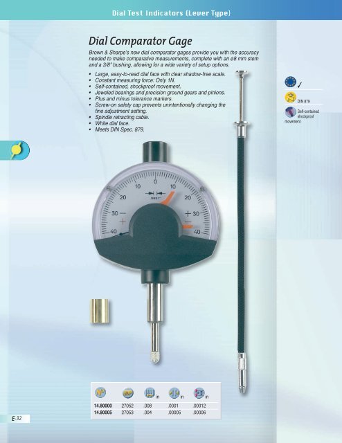
<strong>Dial</strong> <strong>Comparator</strong> <strong>Gage</strong><br />
Brown & Sharpe’s new dial comparator gages provide you with the accuracy<br />
needed to make comparative measurements, complete with an ø8 mm stem<br />
and a 3/8" bushing, allowing for a wide variety of setup options.<br />
Large, easy-to-read dial face with clear shadow-free scale.<br />
Constant measuring force: Only 1N.<br />
Self-contained, shockproof movement.<br />
Jeweled bearings and precision ground gears and pinions.<br />
Plus and minus tolerance markers.<br />
Screw-on safety cap prevents unintentionally changing the<br />
fine adjustment setting.<br />
Spindle retracting cable.<br />
White dial face.<br />
Meets DIN Spec. 879.<br />
in in in<br />
14.80000 27052 .008 .0001 .00012<br />
14.80005 27053 .004 .00005 .00006<br />
✓<br />
DIN 879<br />
Self-contained<br />
shockproof<br />
movement
<strong>Dial</strong> Test Indicators (Lever Type}<br />
® ®<br />
BESTEST / TESATAST <strong>Dial</strong> Test Indicators<br />
All BESTEST and TESATAST indicators meet or exceed federal or DIN<br />
specifications. All BESTEST and TESATAST indicators are fur nished with a<br />
certificate of accuracy and traceability. BESTEST and TESATAST in di ca tors<br />
provide all of the following features:<br />
Constant Clockwise Rotation – Indicator pointer always rotates clockwise<br />
(whether measuring over or under) to elim i nate plus or minus confu sion.<br />
Automatic Reversal – Measuring is bi-directional with double lever system. No<br />
switch to interfere with move ment. Measures inside, outside, over and under.<br />
Swiveling Point – Contact point can be set over 210° arc to measure<br />
hard-to-reach areas.<br />
Universal Mounting – Dovetails top, front and back for required mount ing<br />
ori en ta tion and rigid set up.<br />
Carbide Tip – Furnished as standard on all BESTEST/TESATAST indicators.<br />
Monobloc (precision watch) Body Design – All pinions are mounted in jeweled<br />
bearings in an isolated assembly com pletely separate from outer body to<br />
maintain highest ac cu ra cies.<br />
Anti-Magnetic and Corrosion Resistant – Safe for use around mag net ic<br />
chucks. Chrome plated to resist corrosion.<br />
BESTEST -3 and -13 Series<br />
BESTEST -3 and -13 sets are furnished with .080" carbide contact points,<br />
a rectangular bar, swivel clamp, point wrench and a certificate of accuracy<br />
and traceability. The -3 sets with end mount ed dials are fur nished with a<br />
universal dovetail mounting attachment (7054) in place of the rect an gu lar<br />
bar and swivel clamp.<br />
599-7032-3<br />
E-33
E-34<br />
External Micrometers<br />
Electronic Indicators<br />
<strong>Dial</strong> Test Indicators (Lever Type}<br />
BESTEST/TESATAST -5 Series (Black Face)<br />
BESTEST -5 sets are furnished with a .080" carbide contact point, a .250"<br />
diameter extension with dovetail, point wrench and a cer tif i cate of accuracy<br />
and traceability in a durable molded case.<br />
BESTEST -6 Series (White Face)<br />
BESTEST -6 sets are furnished with 3 carbide contact points, .040", .080", and<br />
.120", 2 extensions with dovetail, point wrench and a certificate of accuracy<br />
and traceability in a durable molded case.<br />
TESATAST<br />
Every TESATAST is furnished with a .080" (2 mm) carbide contact point, a<br />
.310" (8 mm) di am e ter extension with dove tail, a point wrench and a cer tif i cate<br />
of ac cu ra cy and trace abil i ty in a durable molded case.<br />
✓<br />
DIN 2270<br />
NF E 11-053<br />
Rotating dial
Top Mounted Models<br />
<strong>Dial</strong> Test Indicators (Lever Type}<br />
Technical Data<br />
End Mounted Models<br />
Side Mounted Models<br />
Well-proven lever-type dial test indi- Lever-type dial test indicators with Lever-type dial test indicators<br />
cators with dial face mounted parallel dial face mounted at right angle to with dial face mounted parallel<br />
to the insert’s axis.<br />
the insert’s axis.<br />
to the insert’s axis, but on the<br />
flat side of the dial housing.<br />
ø 38,4<br />
ø 28,5<br />
13<br />
24<br />
240°→<br />
15<br />
45<br />
11,8<br />
35,8<br />
8,3 7,6<br />
BESTEST/TESATAST <strong>Dial</strong> Test Indicators (Lever-Type)<br />
These lever-type dial test indicators are especially intended for use on the shop<br />
floor or in the inspection room – Ideally suited for comparative measurements<br />
on a surface plate, for instance – Determine form, shape and positional<br />
deviations, as well as axial and runout errors.<br />
Bi-directional measuring with automatic reversal inside the movement.<br />
Continuous clockwise pointer rotation providing error-free reading.<br />
Insensitive to magnetic fields.<br />
Jeweled movement with 7 rubies.<br />
Ball-bearing lever system with measuring insert swiveling through to 240°.<br />
Very low measuring force.<br />
Full-metal construction giving exceptional durability.<br />
Monobloc housing with 3 countersunk dovetail attachments.<br />
ø 2<br />
70 / 94<br />
11,8<br />
35,8<br />
77 / 101<br />
1.65<br />
60°→<br />
8.54<br />
6.4<br />
ø 1.5<br />
.001"/ .0005"/ .00005"/<br />
0.02 mm 0.01 mm 0.002 mm<br />
.001"/ .0004"/ .0001"/<br />
Deviation span 27 μm 10 μm 2 μm<br />
Deviation span within .0005"/<br />
the local measuring span 0.20 mm 12 μm .0002"/<br />
0.10 mm 5 μm .00005"/<br />
0.02 mm 1 μm<br />
Total deviation span .0012"/<br />
31 μm 13 μm 3.5 μm<br />
.00016"/ .00012"/ .00005"/<br />
Repeatability limit 4 μm 3 μm 1 μm<br />
.00016"/ .00012"/ .00006"/<br />
Max. hysteresis 4 μm 3 μm 1.5 μm<br />
11,8<br />
35,8<br />
Measuring force with the following measuring inserts<br />
12.53 mm long 0.15 N 0.15 N<br />
36.53 mm long 0.06 N 0.06 N<br />
70 / 94<br />
17,4<br />
10,1<br />
E-35
E-36<br />
Accessories<br />
External Micrometers<br />
Electronic Indicators<br />
<strong>Dial</strong> Test Indicators (Lever Type}<br />
TESA IP65 Electronic <strong>Dial</strong> Test<br />
Indicators (Lever-Type)<br />
All the mechanical advantages of a dial test indicator, with a digital<br />
reading and a durable IP65 compliant design.<br />
• Patented inductive measuring system<br />
• Analog and numerical indication<br />
• Numerical interval .0005/.00005 in /<br />
0.01/0.001 mm<br />
• Selectable scale division:<br />
10, 20, 50 µm/1, 2, 5 µm<br />
• IP65 compliant – Water and<br />
coolant resistant<br />
• Inch/metric conversion<br />
• RS-232 data output combined with<br />
external power supply<br />
• Displayed measuring modes<br />
(NOR/MIN/MAX/MAX-MIN)<br />
• Automatic shut down<br />
• Compatible with all TESATAST<br />
accessories<br />
42.5<br />
1.65<br />
18.4<br />
1.5<br />
35<br />
17<br />
60°→<br />
8.54<br />
6.4<br />
1.5<br />
1.5<br />
58.3<br />
12.5<br />
36.5<br />
ø 1.5<br />
(Diagram dimensions shown in mm)<br />
in mm mm Insert N (± 15%)<br />
01830001 29015 .0005/.00005 0.01/0.001 0.8 12.5 0.13<br />
01830002 29016 .0005/.00005 0.01/0.001 0.5 36.5 0.07<br />
01961000 29552 3V lithium battery, 190 mAh, type CR 2032<br />
04761060 29551 RS-232 connection cable with external power supply<br />
Compatible with TESATAST measuring inserts and accessories, page E-47<br />
66.3<br />
8<br />
ø 44<br />
✓<br />
LCD,<br />
5 digits + sign<br />
Digit height:<br />
.24 in / 6 mm<br />
Zero-setting<br />
Max. perm.<br />
error: 10 μm<br />
Repeatability:<br />
1 μm<br />
Hysteresis:<br />
3 μm<br />
01830001<br />
max. 0.05 m/s<br />
01830002<br />
max. 0.15 m/s<br />
Number of<br />
measurements:<br />
9/s<br />
Operating temperature<br />
range:<br />
41 °F to 104 °F<br />
+5 °C to + 40 °C<br />
Lithium battery,<br />
3V, type CR<br />
2032<br />
Autonomie<br />
> 4000 hours<br />
RS-232<br />
01830001<br />
2.57 oz<br />
01830002<br />
2.65 oz<br />
EN 61326-1<br />
Degree of<br />
protection<br />
IEC 529: IP65<br />
Supplied<br />
in a plastic<br />
case with:<br />
1 insert with a .0787 in /<br />
2 mm dia. No. 01860202<br />
1 wrench No. 01860307<br />
1 .315 in / 8 mm dia.<br />
mounting rod No.<br />
01840105<br />
Identification<br />
number<br />
Declaration of<br />
conformity
✓<br />
DIN 2270<br />
NF E 11-053<br />
Rotating dial<br />
<strong>Dial</strong> Test Indicators (Lever Type}<br />
Top Mounted <strong>Dial</strong>s<br />
BESTEST indicators with top mounted dials are supplied with a rectangular<br />
bar, swivel clamp, contact point wrench and a certificate of ac cu ra cy and<br />
traceability in a fitted case. Contact points for models on this page are 1/2"<br />
(12.5 mm) long. Carbide tips are .080" (2 mm) diameter. Available with either<br />
1" (28 mm) or 1-1/2" (38 mm) diameter dials.<br />
TESATAST indicators are supplied in a plastic case with .080" (2 mm) ball-end<br />
carbide contact point, 1 key for fixing the point, 1 extension w/dovetail .31"<br />
(8 mm) diameter, an instruction leaflet and a test certificate.<br />
599-7032-3 599-7030-13 18.20006<br />
Inch Reading (±.0001" Repeatability, ±.0005" Calibration Accuracy)<br />
599-7029-3 45977 18.20010 40507 .001 in .030 in 1 in 0-15-0<br />
599-7030-3 45978 18.20006 40503 .0005 in .030 in 1 in 0-15-0<br />
599-7031-3 45979 18.20007 40504 .0005 in .030 in 1-1/2 in 0-15-0<br />
Inch Reading (±.00002" Repeatability, ±.0001" Calibration Accuracy)<br />
599-7032-3 45980 18.20011 40508 .0001 in .008 in 1 in 0-4-0<br />
599-7023-3 46400 18.20012 40509 .0001 in .008 in 1-1/2 in 0-4-0<br />
599-7033-3 45981 18.20013 40510 .00005 in .008 in 1-1/2 in 0-4-0<br />
Metric Reading (±0.002 mm Repeatability, ±0.01 mm Calibration Accuracy)<br />
599-7030-13 45984 18.10005 40491 0.01 mm 0.8 mm 28 mm 0-0.4-0<br />
599-7031-13 45985 18.10006 40492 0.01 mm 0.8 mm 38 mm 0-0.4-0<br />
Metric Reading (±0.0004 mm Repeatability, ±0.002 mm Calibration Accuracy)<br />
599-7032-13 45986 18.10009 40495 0.002 mm 0.2 mm 28 mm 0-100-0<br />
599-7033-13 45987 18.10010 40496 0.002 mm 0.2 mm 38 mm 0-100-0<br />
<strong>Dial</strong><br />
Dia.<br />
E-37
E-38<br />
Inch Reading<br />
Inch Reading<br />
External Micrometers<br />
Electronic Indicators<br />
<strong>Dial</strong> Test Indicators (Lever Type}<br />
End Mounted <strong>Dial</strong>s<br />
All BESTEST indicators with end mounted<br />
dials come with con tact points 1/2" long<br />
with a carbide tip .080" diameter, a No.<br />
599-7054 universal dovetail mounting<br />
attachment, a contact point wrench<br />
and a certificate of accu racy and<br />
traceability in a fitted case.<br />
599-7037-3 50437 18.20204 40514 .0005 in .030 in 1 in 0-15-0 ±.0001 in .0005 in<br />
599-7024-3<br />
599-7038-3<br />
46406<br />
50436<br />
18.20304<br />
-<br />
40516<br />
-<br />
.0001 in<br />
.00005 in<br />
.008 in<br />
.008 in<br />
1-1/2 in<br />
1-1/2 in<br />
0-4-0<br />
0-4-0<br />
±.00002 in<br />
±.00002 in<br />
.0001 in<br />
.0001 in<br />
Metric Reading<br />
- - 18.10204 40500 0.01 mm 0.8 mm 28 mm 0-0.4-0 ±0.002 mm ±0.01 mm<br />
- - 18.10304 40502 0.002 mm 0.2 mm 38 mm 0-100-0 ±0.0004 mm ±0.002 mm<br />
All TESATAST indicators are supplied in a plastic case with .08 in (2 mm) ball-end carbide contact point, 1 key<br />
for fixing the point, 1 extension w/dovetail .31 in (8 mm) diameter, an instruction leaflet and a test certificate.<br />
Side Mounted <strong>Dial</strong>s<br />
BESTEST indicators with side mounted dials. Contact<br />
points are 1/2" long. Car bide tip is .080" diameter. Ideal for<br />
height gages, transfer gages and Digit-Hite ® plus. Supplied<br />
with a rect an gu lar bar, swivel clamp, contact point wrench,<br />
and a certificate of accuracy and trace abil i ty in a fitted case.<br />
599-7021-3 50566 .0005 in .030 in 1-1/2 in 0-15-0 ±.0001 in ±.0005 in<br />
18.20014 40511 .0005 in .030 in 1 in 0-15-0 ±.0001 in ±.0005 in<br />
599-7022-3 50567 .00005 in .008 in 1-1/2 in 0-4-0 ±.00002 in ±.0001 in<br />
18.20015 40512 .0001 in .008 in 1 in 0-4-0 ±.00002 in ±.0001 in<br />
Metric Reading<br />
<strong>Dial</strong><br />
Dia.<br />
<strong>Dial</strong><br />
Dia.<br />
18.10011 40497 0.01 mm 0.8 mm 28 mm 0-0.4-0 ±0.002 mm ±0.01 mm<br />
18.10013 40499 0.002 mm 0.2 mm 28 mm 0-100-0 ±0.0004 mm ±0.002 mm<br />
✓<br />
DIN 2270<br />
NF E 11-053<br />
Rotating dial
✓<br />
DIN 2270<br />
NF E 11-053<br />
Rotating dial<br />
<strong>Dial</strong> Test Indicators (Lever Type}<br />
Easy Reading Console Faces<br />
BESTEST -5 Series (Black Face)<br />
Easy-to-read, satin-black, “jet console” face, BESTEST ® in di ca tors with high<br />
visibility orange hand. BESTEST -5 sets are fur nished with a .080" carbide<br />
contact point, a .250" diameter extension with dovetail, point wrench and a<br />
certificate of accuracy and trace abil i ty in a durable molded case.<br />
in in<br />
<strong>Dial</strong><br />
Dia.<br />
(in)<br />
599-7029-5 51732 .001 .030 1 0-15-0 1/2<br />
599-7030-5 51733 .0005 .030 1 0-15-0 1/2<br />
599-7031-5 51734 .0005 .030 1-1/2 0-15-0 1/2<br />
599-7032-5 51737 .0001 .008 1 0-4-0 1/2<br />
599-7033-5 51738 .00005 .008 1-1/2 0-4-0 1/2<br />
599-7034-5 51735 .0005 .020 1 0-10-0 1-7/16<br />
599-7035-5 51736 .0005 .020 1-1/2 0-10-0 1-7/16<br />
Inserts<br />
(in)<br />
E-39
E-40<br />
External Micrometers<br />
Electronic Indicators<br />
<strong>Dial</strong> Test Indicators (Lever Type}<br />
BESTEST -6 and -14 Series (White Face)<br />
BESTEST -6 and -14 sets are fur nished with 3 car bide contact points, .040",<br />
.080" and .120", one 1/2" long x .25" di am e ter extension with dove tail, one<br />
1/2" long x .22" di am e ter ex ten sion with dovetail, a contact point wrench and<br />
a cer tif i cate of accuracy and trace abil i ty in a durable molded case.<br />
Inch Reading (±.0001" Repeatability, ±.0005" Calibration Accuracy)<br />
599-7030-6 25925 .0005 in .030 in 1 in 0-15-0<br />
599-7031-6 25926 .0005 in .030 in 1-1/2 in 0-15-0<br />
Inch Reading (±.00002" Repeatability, ±.0001" Calibration Accuracy)<br />
<strong>Dial</strong><br />
Dia.<br />
599-7032-6 25929 .0001 in .008 in 1 in 0-4-0<br />
599-7023-6 25923 .0001 in .008 in 1-1/2 in 0-4-0<br />
Metric Reading (±0.001 mm Repeatability, ±0.01 mm Cali bra tion Accuracy)<br />
599-7030-14 25927 0.01 mm 0.8 mm 28 mm 0-0.4-0<br />
599-7031-14 25928 0.01 mm 0.8 mm 38 mm 0-0.4-0<br />
Metric Reading (±0.0002 mm Repeatability, ±0.002 mm Calibration Accuracy)<br />
599-7032-14 25930 0.002 mm 0.2 mm 28 mm 0-100-0<br />
✓<br />
DIN 2270<br />
NF E 11-053<br />
Rotating dial
✓<br />
DIN 2270<br />
NF E 11-053<br />
Rotating dial<br />
External Micrometers<br />
<strong>Dial</strong> Test Indicators (Lever Type}<br />
Extra Long Contact Points<br />
BESTEST indicators with top mounted dials. Contact points are 1-7/16" long.<br />
Carbide tip is .080" di am e ter. Supplied with a rectangular bar, swivel clamp,<br />
contact point wrench and a certificate of accuracy and traceability in a fitted case.<br />
All TESATAST indicators are supplied in a plastic case with .080" (2 mm)<br />
ball-end carbide contact point,1 key for fixing the point, a .31" (8 mm) diameter<br />
extension with dovetail, an instruction leaflet and a test certificate.<br />
Top Mounted Inch Reading (±.0001" Repeatability, ±.0005" Calibration Accuracy)<br />
599-7034-3 45982 18.20008 40505 .0005 in .020 in 1 in 0-10-0<br />
599-7035-3 45983 18.20009 40506 .0005 in .020 in 1-1/2 in 0-10-0<br />
Vertical/End Inch Reading (±.0001" Repeatability, ±.0005" Calibration Accuracy)<br />
- -<br />
18.20205 40515 .0005 in .020 in 1 in 0-10-0<br />
Side Mount Inch Reading (±.0001" Repeatability, ±.0005" Calibration Accuracy)<br />
- -<br />
18.20016 40513 .001 in .020 in 1-1/2 in 0-40-0<br />
Top Mounted Metric Reading (±0.002 mm Repeatability, ±0.01 mm Calibration Accuracy)<br />
- -<br />
- -<br />
18.10007 40493 0.01 mm 0.5 mm 28 mm 0-0.25-0<br />
18.10008 40494 0.01 mm 0.5 mm 38 mm 0-0.25-0<br />
Vertical/End Metric Reading (±0.002 mm Repeatability, ±0.01 mm Calibration Accuracy)<br />
- -<br />
18.10205 40501 0.01 mm 0.5 mm 28 mm 0-0.25-0<br />
Side Mount Metric Reading (±0.002 mm Repeatability, ±0.01 mm Calibration Accuracy)<br />
- -<br />
<strong>Dial</strong><br />
Dia.<br />
18.10012 40498 0.02 mm 0.2 mm 38 mm 0-0.1-0<br />
E-41
E-42<br />
External Micrometers<br />
Electronic Indicators<br />
<strong>Dial</strong> Test Indicators BESTEST Accessories<br />
BESTEST Universal Test Indicators<br />
Full jewelled movement in a universal indicator<br />
599-7739 44892 A. Inch Indicator Set complete with case<br />
599-7739-10 45705 B. Metric Indicator Set complete with case<br />
Components for Indicator Set ( Inch and Metric)<br />
599-7739-1 44893 C. Swivel for Posts .312” diameter and mounting rods .220” to .250’ diameter<br />
599-7739-2 44894 D. Clamp: 1-5/16" range and 1/4-28 threaded hole<br />
599-7739-3 44895 E. Hole Attachment w/ Indicator Mounting Hole .375" dia. and<br />
finger 7/32" dia. w/ 1-7/8" reach<br />
599-7739-4 44896 F. Bar: 5-5/16" long x 3/8" thick x 3/4" high w/ tapped thru holes<br />
at top, bottom and both sides of front and one tapped hole at<br />
back end for attaching Holding Rods<br />
599-7739-5 44897 G. Holding Rod: .312" x 5" long<br />
599-7739-6 44898 H. Holding Rod: .312" x 3" long<br />
599-7739-9999 44899 I. Fitted Case for indicator and accessories
<strong>Dial</strong> Test Indicators BESTEST Accessories<br />
<strong>Dial</strong> Test Indicators - BESTEST® Accessories<br />
A<br />
B<br />
C<br />
D<br />
Components for Accessory Set<br />
599-7046 44861 A. Rectangular bar 3/16" thick x 5/16" high x 3" long with .220" diameter stud<br />
599-7048 44863 B. Round bar 7/32" diameter with .163" stepped end; .220" diameter stud;<br />
2-7/8" long<br />
599-7042 44857 C. Swivel support (short) 3/8" diameter x 1" long shank<br />
599-7043 44858 D. Angle attachment 3/8" hole with 3/8" diameter x 1" long shank<br />
599-7052 44867 E. Extension with dovetail .220" diameter x 1/2" long shank<br />
599-7053 44868 F. Extension with dovetail .250" diameter x 1/2" long shank<br />
599-7030-40 44827 G. Carbide ball contact point .040" diameter x 1/2" long<br />
599-7030-120 44829 H. Carbide ball contact point .120" diameter x 1/2" long<br />
599-7041 44856 Complete set of accessories (A-H above)<br />
Additional Accessories<br />
599-7047 44862 I. Rectangular bar: Furnished with all front-mounted BESTEST indicators.<br />
1/4" thick x 1/2" high x 3" long with .220" diameter stud<br />
599-7044 44859 J. Swivel support (long): 3/8" diameter x 3-5/8" long shank<br />
E<br />
G H<br />
F<br />
I<br />
J<br />
E-43
E-44<br />
External Micrometers<br />
Electronic Indicators<br />
<strong>Dial</strong> Test Indicators BESTEST Accessories<br />
Universal Clamp<br />
For mounting in di ca tor on dovetail. 7/32" hole in swivel. Dovetail end has 7/32"<br />
hole and 5/32" hole adjacent to the dovetail. For use on Interapid 312 style<br />
indicators.<br />
Universal Swivel Clamp<br />
74.108603 41663<br />
Dovetail opposite 3/8" mounting hole and V-side hole with clamp screw for<br />
range 1/8" to 1/4".<br />
Swivel Clamp<br />
599-7055 44870<br />
3/8" and 7/32" dia. mounting holes. Dove tail opposite 3/8" hole. For use with<br />
all front-mounted dial BESTEST/TESATAST in di ca tors.<br />
599-7045-1 51853
<strong>Dial</strong> Test Indicators BESTEST Accessories<br />
Universal Dovetail At tach ment<br />
Supplied with vertical top-mounted dial BESTEST in di ca tors. Fits all BESTEST<br />
indi cators and dovetail-mounting elec tron ic gage heads. Chrome plated.<br />
Shank is 1/4" diameter x 2-1/2" long (to center of ball).<br />
Lug-Back Bracket<br />
599-7054 44869<br />
Dovetail fits all BESTEST in di ca tors and dovetail-mount ing electronic heads.<br />
Mounting slot is 1/4".<br />
599-980-10 44740<br />
Combination BESTEST Indicator Axial Support<br />
Used for mounting indicator on dovetail or rod. Hinges on support allow<br />
indicator to be positioned for best orientation to work piece. Support mounting<br />
stem is 3/8". Tool length is 5-1/4".<br />
74.106931 41656<br />
E-45
E-46<br />
Contact Points<br />
External Micrometers<br />
Electronic Indicators<br />
<strong>Dial</strong> Test Indicators BESTEST Accessories<br />
Contact points of different lengths are not in ter change able because any change in<br />
length of point radically changes the mag ni fi ca tion of the indicator. Be sure to<br />
replace or interchange only with points of the same length. Points of the same<br />
length but having different tip di am e ters are com plete ly interchangeable.<br />
599-7030-15 599-7051<br />
599-7030-40<br />
599-7034-40<br />
599-7030-80<br />
599-7034-120<br />
Ruby Tip Contact Points<br />
599-7050<br />
599-7036-80<br />
599-7030-120<br />
599-7030-40R 599-7030-80R<br />
599-7034-80R<br />
599-7034-80<br />
599-7049<br />
Length x Tip Dia. (in / mm) Ball Material<br />
For use with BESTEST indicators 599-7021, 7022, 7023, 7024, 7029, 7030, 7031, 7032, 7033, 7037, and<br />
7038 inch and metric models:<br />
599-7030-15 45702 1/2 x .015 / 12.5 x 0.4 Carbide<br />
599-7030-40 44827 1/2 x .040 / 12.5 x 1 Carbide<br />
599-7050 44865 1/2 x .040 / 12.5 x 1 Steel<br />
599-7030-80 44828 1/2 x .080 / 12.5 x 2 Carbide<br />
599-7049 44864 1/2 x .080 / 12.5 x 2 Steel<br />
599-7030-120 44829 1/2 x .120 / 12.5 x 3 Carbide<br />
599-7051 44866 1/2 x .120 / 12.5 x 3 Steel<br />
For use with 599-7034 and 599-7035 BESTEST indicators:<br />
599-7034-40 44841 1-7/16 x .040 / 37 x 1 Carbide<br />
599-7034-80 44842 1-7/16 x .080 / 37 x 2 Carbide<br />
599-7036-80 44847 1-7/16 x .080 / 37 x 2 Steel<br />
599-7034-120 44843 1-7/16 x .120 / 37 x 3 Carbide<br />
Ruby Tip Contact Points<br />
599-7030-40R 24694 1/2 x .040 / 12.5 x 1 Synthetic Sapphire<br />
599-7030-80R 24695 1/2 x .080 / 12.5 x 2 Synthetic Sapphire<br />
599-7030-120R 24696 1/2 x .120 / 12.5 x 3 Synthetic Sapphire<br />
599-7034-80R 24697 1-7/16 x .080 / 37 x 2 Synthetic Sapphire<br />
599-7034-120R 24698 1-7/16 x .120 / 37 x 3 Synthetic Sapphire<br />
Contact point thread size is M1.4 x 0.3<br />
599-7034-120R<br />
599-7030-120R
<strong>Dial</strong> Test Indicators BESTEST Accessories<br />
<strong>Dial</strong> Test Indicators - TESATAST® Accessories<br />
Styli are available with various ball tip diameters and lengths in either hard-chrome<br />
plated or carbide ball tips.<br />
18.60201<br />
18.60202<br />
18.60203<br />
Hard-chrome Car bide<br />
18.60211<br />
18.60212<br />
18.60213<br />
Ball Tip<br />
in/mm<br />
18.60101 40542 18.60201 40548 .04 / 1 .5 / 12.5<br />
18.60102 40543 18.60202 40549 .08 / 2 .5 / 12.5<br />
18.60103 40544 18.60203 40550 .12 / 3 .5 / 12.5<br />
18.60112 40546 18.60211 40551 .04 / 1 1.5 / 36.5<br />
18.60113 40547 18.60212 40552 .08 / 2 1.5 / 36.5<br />
18.60213 40553 .12 / 3 1.5 / 36.5<br />
Note: Same point for both inch and metric instruments<br />
in/mm<br />
E-47
E-48<br />
External Micrometers<br />
Electronic Indicators<br />
<strong>Dial</strong> Test Indicators (Lever Type)<br />
TESATAST Accessories<br />
1 2 3<br />
7<br />
4 5<br />
6<br />
in mm<br />
Fixing shanks and supports for clamping the TESATAST in the measuring position.<br />
Dovetail shanks:<br />
18.50104 40533 18.40104 40522 1. 7/32 in (8 mm) x .5 in (12 mm)<br />
18.50105 40534 18.40105 40523 2. 1/4 in (8 mm) x .5 in (12 mm)<br />
Rod shank:<br />
18.50202 40535 18.40202 40524 3. 3/8 in (8 mm) dia. x 3.5 in (80 mm)<br />
Oblong section shank:<br />
18.50203 40536 18.40203 40525 4. 1/2 in x 1/4 in x 3 in (13 x 6 x 75 mm)<br />
Swivel shanks:<br />
18.50404 40537 18.40404 40526 5. 3/8 in (8 mm) dia. x 1 in (25 mm)<br />
18.50405 40538 18.40405 40527 6. 3/8 in (8 mm) dia. x 3.5 in (90 mm)<br />
8<br />
Angle shanks:<br />
18.50406 40539 18.40406 40528 7. 3/8 in (8 mm) dia. x 1 in (25 mm)<br />
18.40501 40529 18.40501 40529 8. Centering support with shank 3/8 in (8 mm) dia. x 1 in<br />
(25 mm) clamping by dovetail and 3/16 in (4 mm) bore<br />
18.60401 40557 18.60401 40557 9. Fixing clamp, double<br />
Sets and additional accessories:<br />
18.50001 40531 18.40001 40519 Set of accessories consisting of: 18.60101 stylii,<br />
18.60102 stylii, 18.60103 stylii, 18.60307 key holder,<br />
18.50104 dovetail shank or 18.40104 dovetail shank,<br />
18.50105 dovetail shank or 18.40105 dovetail shank,<br />
18.60308 case<br />
18.50100 40532 18.40100 40521 Set of accessories consisting of: 18.60401 clamp,<br />
18.50202 shank or 18.40202 shank,<br />
18.50203 support or 18.40203 support,<br />
18.50404 shank or 18.40404 shank,<br />
18.50405 shank or 18.40405 shank,<br />
18.50406 shank or 18.40406 shank, 18.60608 case<br />
18.50703 40540 18.40703 40530 Set similar to 18.50101 or 18.40101 but with centering<br />
support 18.40501 in addition, in case 18.60702<br />
18.60307 40555 18.60307 40555 Stylus key<br />
9
✓<br />
A<br />
B<br />
<strong>Dial</strong> Test Indicators (Lever Type)<br />
INTERAPID ® 312 <strong>Dial</strong> Test Indicators<br />
(Lever-Type)<br />
Very large measuring span – Ideal for inspecting all significant size variations,<br />
e.g. on the surface plate – Measure positional, form and shape errors.<br />
Measuring<br />
direction<br />
Measuring<br />
direction<br />
Measuring<br />
direction<br />
For measurement at 12°.<br />
With revolution counter.<br />
Inclined, easy-to-read dial.<br />
One piece, solid case.<br />
High rigidity.<br />
Very high sensitivity, very light measuring pressure.<br />
Jeweled mechanism fitted with ball-bearings.<br />
Fully reversible, swiveling through 210° without reversing lever.<br />
Hard steel or tungsten carbide contact points.<br />
Variety of mounting positions.<br />
Angular position of 12° for stylus<br />
insert<br />
The models INTERAPID 312 are<br />
designed to give a true reading when<br />
the angle between the stylus and the<br />
workpiece surface is 12° (Fig. A).<br />
In other measuring positions, including<br />
the parallel position of the stylus<br />
against the workpiece surface, the<br />
values read have to be corrected<br />
(Fig. B).<br />
Horizontal Model<br />
Time-tested dial test<br />
indicator (lever-type) with<br />
dial face mounted parallel<br />
to the insert axis.<br />
Technical Data<br />
Vertical Model<br />
<strong>Dial</strong> test indicator (levertype)<br />
with dial face mounted<br />
at right angle to the insert<br />
axis.<br />
0.01 mm 0.002 mm<br />
Pointer Revolution<br />
1 2<br />
Pointer Revolution<br />
1 2<br />
Deviation range 10 μm 20 μm 4 μm 8 μm<br />
Total deviation range 13 μm 23 μm 6 μm 10 μm<br />
Repeatability limit 3 μm 1 μm<br />
Max. hysteresis 3 μm 2 μm<br />
Measuring force 0.12 N 0.25 N<br />
E-49
E-50<br />
20<br />
10<br />
30<br />
0<br />
0.01 mm<br />
40<br />
10<br />
30<br />
20<br />
External Micrometers<br />
Electronic Indicators<br />
<strong>Dial</strong> Test Indicators (Lever Type)<br />
INTERAPID® 312 Horizontal Models<br />
Series<br />
Bezel<br />
Dia.<br />
Inserts<br />
in<br />
74.111370 42775 312b-1 0.0005 0.060 1.5 0 - 15 - 0 0.65<br />
74.111371 86150 312b-2 0.0005 0.060 1.2 0 - 15 - 0 0.65<br />
74.111965 41716 312b-15 0.0005 0.060 1.5 0 - 15 - 0 2.675<br />
74.111374 41682 312b-20 0.001 0.060 1.2 0 - 15 - 0 0.65<br />
74.111372 41680 312b-3 0.0001 0.016 1.5 0 - 4 - 0 0.65<br />
74.111373 41681 312b-4 0.0001 0.016 1.2 0 - 4 - 0 0.65<br />
mm<br />
74.111366 41674 312-1 0.01 1.6 37.5 0 - 40 - 0 16.5<br />
74.111367 41675 312-2 0.01 1.6 30.0 0 - 40 - 0 16.5<br />
74.111368 42773 312-3 0.002 0.4 37.5 0 - 10 - 0 15.2<br />
74.111369 42774 312-4 0.002 0.4 30.0 0 - 10 - 0 15.2<br />
20<br />
10<br />
30<br />
0<br />
0.01 mm<br />
40<br />
74.111366 74.111367 74.111368 74.111369<br />
INTERAPID® 312 Vertical Models<br />
10<br />
30<br />
20<br />
4<br />
6<br />
2<br />
8<br />
0<br />
0.002 mm<br />
10<br />
2<br />
8<br />
4<br />
6<br />
Bezel<br />
Dia.<br />
4<br />
6<br />
2<br />
8<br />
0<br />
0.002 mm<br />
in<br />
74.111377 41685 0.0005 0.060 1.5 0 - 15 - 0 0.65<br />
74.111378 41686 0.0005 0.060 1.2 0 - 15 - 0 0.65<br />
74.111958 41715 0.0005 0.060 1.5 0 - 15 - 0 2.675<br />
74.111379 41687 0.001 0.060 1.2 0 - 15 - 0 0.65<br />
74.111957 41714 0.0001 0.016 1.5 0 - 4 - 0 0.65<br />
mm<br />
74.111375 41683 0.01 1.6 37.5 0 - 40 - 0 16.5<br />
74.111376 41684 0.01 1.6 30.0 0 - 40 - 0 16.5<br />
10<br />
2<br />
8<br />
4<br />
6<br />
Inserts<br />
✓<br />
Rotating<br />
dial<br />
Very low measuring<br />
force as in<br />
the table on page E-45<br />
Lever system<br />
with friction<br />
drive preventing from<br />
overload<br />
Accuracy:<br />
see table on<br />
page E-45<br />
Supplied in a<br />
plastic case<br />
with:<br />
1 insert with a<br />
.080 in / 2 mm dia.<br />
in hardened steel<br />
1 key No. 18.60307<br />
Identification<br />
number<br />
Declaration<br />
of conformity
✓<br />
Technical<br />
data as listed<br />
under each<br />
single product<br />
Plastic case<br />
Identification<br />
number<br />
Declaration<br />
of conformity<br />
<strong>Dial</strong> Test Indicators (Lever Type)<br />
Full Indicator Sets with Accessories<br />
Full sets consist of:<br />
INTERAPID® 312 Horizontal Models<br />
INTERAPID 312 dial test indicators<br />
as shown in the tables hereafter<br />
74.106331 41651 Height gage bar with clamp<br />
74.108943 41665 Reducing sleeve, inch<br />
or<br />
74.108942 41664 Adapter sleeve 5/32" - 3/8"<br />
74.106931 41656 Axial support - .375" stem<br />
or<br />
74.106026 41650 Axial support - 8 mm stem<br />
74.111474 41688 Case for contact points<br />
18.60307 40555 Contact point wrench<br />
in 74.111370 74.111371 74.111372 74.111373 74.106331 74.108943 74.106931 74.111474 18.60307<br />
74.111508 41706 ● ● ● ● ● ●<br />
74.111509 41707 ● ● ● ● ● ●<br />
74.111510 41708 ● ● ● ● ● ●<br />
74.111511 41709 ● ● ● ● ● ●<br />
mm 74.111366 74.111367 74.111368 74.111369 74.106331 74.108942 74.106026 74.111474 18.60307<br />
74.111502 41700 ● ● ● ● ● ●<br />
74.111503 41701 ● ● ● ● ● ●<br />
74.111504 42777 ● ● ● ● ● ●<br />
74.111505 42778 ● ● ● ● ● ●<br />
INTERAPID® 312 Vertical Models<br />
in 74.111377 74.111378 74.106331 74.108943 74.106931 74.111474 18.60307<br />
74.111513 41710 ● ● ● ● ● ●<br />
74.111514 41711 ● ● ● ● ● ●<br />
mm 74.111375 74.111376 74.106331 74.108942 74.106026 74.111474 18.60307<br />
74.111506 41704 ● ● ● ● ● ●<br />
74.111507 41705 ● ● ● ● ● ●<br />
E-51
E-52<br />
External Micrometers<br />
Electronic Indicators<br />
<strong>Dial</strong> Test Indicators (Lever Type)<br />
Measuring Inserts for INTERAPID® 312<br />
Series 312 <strong>Dial</strong> Test Indicator Sets<br />
Length L of the measuring inserts<br />
L<br />
Steel<br />
Ball Tips<br />
Carbide<br />
Ball Tips<br />
Note:<br />
The original measuring insert mounted on<br />
every INTERAPID 312 and other inserts with<br />
same nominal length but having different tip<br />
diameters are completely interchangeable.<br />
in<br />
74.107899 41660 74.105996 41647 all** 0.080 0.650<br />
74.107901 41661 74.105997 41648 all** 0.060 0.650<br />
74.107903 41662 74.105998 41649 all** 0.031 0.650<br />
74.106361 41654 all** 0.080 1.375*<br />
74.106363 41655 all** 0.031 1.375*<br />
74.111913*** 41713 0.080 2.675<br />
74.111912**** 41712 0.100 2.675<br />
mm<br />
74.107893 41657 74.105993 41644 0.01 2 16.5<br />
74.107895 41658 74.105994 41645 0.01 1.5 16.5<br />
74.107897 41659 74.105995 41646 0.01 0.8 16.5<br />
74.106358 41652 0.01 2 36.6*<br />
74.106360 41653 0.01 0.8 36.6*<br />
74.110481 41666 74.110482 41667 0.002 2 15.2<br />
74.110492 41669 74.110491 41668 0.002 1.5 15.2<br />
74.110493 41670 74.110507 42772 0.002 0.8 15.2<br />
74.110494 41671 0.002 2 34*<br />
74.110508 41673 0.002 0.8 34*<br />
in / mm<br />
18.60307 40555 Key for measuring inserts<br />
74.111474 41688 Case for measuring inserts<br />
* The length of the used insert changes the amplification factor of the lever system,<br />
therefore, each read value must be doubled.<br />
** Except for models No. 74.111965 and No. 74.111958<br />
*** Only for model No. 74.111965<br />
**** Only for model No. 74.111958<br />
L<br />
✓<br />
Ball tips in<br />
hardened steel<br />
or tungsten carbide<br />
M1.7<br />
coupling thread
✓<br />
74.106331<br />
3 + 2 = 1<br />
<strong>Dial</strong> Test Indicators (Lever Type)<br />
Accessories for INTERAPID® 312<br />
Type<br />
74.106931<br />
74.108942<br />
in mm in mm<br />
74.106331 41651 Height gage bar with clamp 74.106331 41656<br />
18.50203 40536 Height gage bar 18.40203 40525 1 /2 x 1 /4 x 2 13 x 6 x 50<br />
ø 7 /32 ø 5.6<br />
74.108603 41663 Double attachment with clamping 74.108603 41663 ø 4<br />
point and dovetail<br />
74.106931 41656 Swivel holder 74.106026 41650 ø 3 /8 x 5.25 ø 8 x 133<br />
with clamping points ø 4<br />
and dovetail<br />
74.108943 41665 Reducing sleeve 74.108942 41664 ø 3 /8 / ø 5 /32 ø 8 / ø 4<br />
74.111481 41689 Rectangular fixing shank 3 /16 x 5 /16<br />
Contact Points For INTERAPID® Models 310-3, 311-3, 310-b-3,<br />
311-bn-3, 312-3, 312-4†<br />
74.111486 42776 Carbide .080 in .812 in<br />
74.111487 41693 Carbide .060 in .812 in<br />
74.111488 41694 Carbide .031 in .812 in<br />
74.111489 41695 Chrome .080 in .812 in<br />
74-111490 41696 Chrome .060 in .812 in<br />
74.111491 41697 Chrome .031 in .812 in<br />
74.111492* 41698 Carbide .080 in 1.750 in<br />
74.111493* 41699 Carbide .031 in 1.750 in<br />
74.110481 41666 Chrome 2.0 mm 15.2 mm<br />
74.110482 41667 Carbide 2.0 mm 15.2 mm<br />
74.110491 41668 Carbide 1.5 mm 15.2 mm<br />
74.110493 41670 Chrome 0.8 mm 15.2 mm<br />
74.110494* 41671 Carbide 2.0 mm 34 mm<br />
74.110507 42772 Carbide 0.8 mm 15.2 mm<br />
74.110508* 41673 Carbide 0.8 mm 34 mm<br />
† With .0001 in (0.002 mm) graduations<br />
* Note when these special purpose contact points are used, the dial reading must be<br />
doubled to obtain the correct reading!<br />
E-53
E-54<br />
A<br />
B<br />
Measuring direction<br />
Measuring direction<br />
Metric reading<br />
Lever <strong>Dial</strong> Test Indicators<br />
COMPAC Lever <strong>Dial</strong> Test Indicators<br />
Essential for the workshop, but also in the inspection room and laboratory<br />
– Ideal for comparative measurement on a surface plate – Detect form and<br />
position errors – Measure axial and radial runouts, especially.<br />
Note for use of the COMPAC dial test indicators (lever-type):<br />
When the measuring insert is parallel to the workpiece surface (Fig. A), these dial<br />
test indicators give true reading as the amplification factor is 1:1.<br />
In other measuring positions (angle α in Fig. B), the effective lever length changes<br />
so that the read value need be corrected. With respect to this, also refer to the instruction manual.<br />
Inch reading<br />
α<br />
Shorten lever<br />
Technical features:<br />
• Long range up to 3 mm.<br />
• Bi-directional measuring, without reversing lever.<br />
• Continuous clockwise rotation of the pointer in both ways.<br />
• Swivelling probe through 180°.<br />
• Main pivot on oversized, self-aligning angular bearings.<br />
• Dovetail mounting directly machined in the indicator body.<br />
• Dull-chrome plated bezel and housing.<br />
• Rotating dial.<br />
• Insensitive to magnetic fields produced in universal preci-<br />
sion mechanics.<br />
Series 210, standard<br />
Order Reading Total Travel per Bezel Contact Total Repeat- Hysteresis N<br />
Code Range Revolution Point Reading ability<br />
in in in in L in error (in) in in<br />
212A .001 .06 .02 1.063 0-10-20 .72 .0005 .00015 .00015 ≤ 0.35<br />
214A .0005 .06 .02 1.063 0-10-20 .72 .0005 .00015 .00015 ≤ 0.35<br />
214GA .0005 .06 .02 1.575 0-10-20 .72 .0005 .00015 .00015 ≤ 0.35<br />
213LA .0005 .12 .04 1.063 0-20-40 1.44 .001 .00015 .00025 ≤ 0.20<br />
213GLA .0005 .12 .04 1.575 0-20-40 1.44 .001 .00015 .00025 ≤ 0.20<br />
215A .0001 .024 .004 1.063 0-20-40 .72 .0005 .00015 .0001 ≤ 0.30<br />
215GA .0001 .024 .004 1.575 0-20-40 .72 .0005 .00015 .0001 ≤ 0.30<br />
Order Reading Total Travel per Bezel Contact Total Repeat- Hysteresis N<br />
code Range Revolution Point Reading ability<br />
mm mm mm mm L mm error (μm) μm μm<br />
213 0.01 1.5 0.5 27 0-25-50 18 13 3 3 ≤ 0.35<br />
213G 0.01 1.5 0.5 40 0-25-50 18 13 3 3 ≤ 0.35<br />
212L 0.01 3 1 27 0-50-100 36 26 3 6 ≤ 0.20<br />
212GL 0.01 3 1 40 0-50-100 36 26 3 6 ≤ 0.20<br />
215 0.002 0.6 0.1 27 0-5-10 18 13 1.5 2.5 ≤ 0.30<br />
215G 0.002 0.6 0.1 40 0-5-10 18 13 1.5 2.5 ≤ 0.30<br />
215GL 0.002 1.2 0.2 40 0-10-20 36 26 5 5 ≤ 0.20<br />
216G 0.001 0.6 0.1 40 0-5-10 18 4 1.5 1.5 ≤ 0.30<br />
1.6<br />
60∞<br />
6.38<br />
ø 0.79<br />
✓<br />
DIN 2270 and<br />
factory standard<br />
Rotating dial<br />
Friction lever<br />
system for<br />
preventing<br />
from overload<br />
Contact points<br />
with tungsten<br />
carbide ball tips<br />
Delivery in a<br />
suited plastic<br />
case including:<br />
1 x 2 mm dia. contact point<br />
1 x 8 mm dia. rigid stem,<br />
L = 15 mm<br />
(No. 01840107)<br />
1 x 4 mm dia. rigid stem,<br />
L = 15 mm<br />
(No. 01840109)<br />
Serial number<br />
Inspection report<br />
with a declaration<br />
of conformity
Lever <strong>Dial</strong> Test Indicators<br />
Series 220, perpendicular<br />
Inch reading<br />
Order Reading Total Travel per Bezel Contact Total Repeat- Hysteresis N<br />
Code Range Revolution Point Reading ability<br />
in in in in L in error (in) in in<br />
224A .0005 .06 .02 1.063 0-10-20 .72 .0005 .00015 .00015 ≤ 0.35<br />
224GA .0005 .06 .02 1.575 0-10-20 .72 .0005 .00015 .00015 ≤ 0.35<br />
223LA .0005 .12 .04 1.063 0-20-40 1.44 .001 .00015 .00025 ≤ 0.20<br />
223GLA .0005 .12 .04 1.575 0-20-40 1.44 .001 .00015 .00025 ≤ 0.20<br />
225A .0001 .024 .004 1.063 0-20-40 .72 .0005 .0001 .00015 ≤ 0.30<br />
225GA .0001 .024 .004 1.575 0-20-40 .72 .0005 .0001 .00015 ≤ 0.30<br />
Metric reading<br />
Order Reading Total Travel per Bezel Contact Total Repeat- Hysteresis N<br />
Code Range Revolution Point Reading ability<br />
mm mm mm mm L mm error (μm) μm μm<br />
223 0.01 1.5 0.5 27 0-25-50 18 13 3 3 ≤ 0.35<br />
223G 0.01 1.5 0.5 40 0-25-50 18 13 3 3 ≤ 0.35<br />
222L 0.01 3 1 27 0-50-100 36 26 3 6 ≤ 0.20<br />
222GL 0.01 3 1 40 0-50-100 36 26 3 6 ≤ 0.20<br />
225 0.002 0.6 0.1 27 0-5-10 18 13 1.5 2.5 ≤ 0.30<br />
225G 0.002 0.6 0.1 40 0-5-10 18 13 1.5 2.5 ≤ 0.30<br />
E-55
E-56<br />
Inch reading<br />
Metric reading<br />
Series 230, parallel<br />
Lever <strong>Dial</strong> Test Indicators<br />
Order Reading Total Travel per Bezel Contact Total Repeat- Hysteresis N<br />
Code Range Revolution Point Reading ability<br />
in in in in L in error (in) in in<br />
234A .0005 .06 .02 1.063 0-10-20 .72 .0005 .00015 .00015 ≤ 0.35<br />
234GA .0005 .06 .02 1.575 0-10-20 .72 .0005 .00015 .00015 ≤ 0.35<br />
233LA .0005 .12 .04 1.063 0-20-40 1.44 .001 .00015 .00025 ≤ 0.20<br />
233GLA .0005 .12 .04 1.575 0-20-40 1.44 .001 .00015 .00025 ≤ 0.20<br />
235A .0001 .024 .004 1.063 0-20-40 .72 .0005 .0001 .00015 ≤ 0.30<br />
235GA .0001 .024 .004 1.575 0-20-40 .72 .0005 .0001 .00015 ≤ 0.30<br />
Order Reading Total Travel per Bezel Contact Total Repeat- Hysteresis N<br />
Code Range Revolution Point Reading ability<br />
mm mm mm mm L mm error (μm) μm μm<br />
233 0.01 1.5 0.5 27 0-25-50 18 13 3 3 ≤ 0.35<br />
233G 0.01 1.5 0.5 40 0-25-50 18 13 3 3 ≤ 0.35<br />
232L 0.01 3 1 27 0-50-100 36 26 6 3 ≤ 0.20<br />
232GL 0.01 3 1 40 0-50-100 36 26 6 3 ≤ 0.20<br />
235 0.002 0.6 0.1 27 0-5-10 18 13 1.5 2.5 ≤ 0.30<br />
235G 0.002 0.6 0.1 40 0-5-10 18 13 1.5 2.5 ≤ 0.30<br />
✓<br />
DIN 2270 and<br />
factory standard<br />
Rotating dial<br />
Friction lever<br />
system for<br />
preventing<br />
from overload<br />
Contact points<br />
with tungsten<br />
carbide ball tips<br />
Delivery in a<br />
suited plastic<br />
case including:<br />
1 x 2 mm dia. contact point<br />
1 x 8 mm dia. rigid stem,<br />
L = 15 mm<br />
(No. 01840107)<br />
1 x 4 mm dia. rigid stem,<br />
L = 15 mm<br />
(No. 01840109)<br />
Serial number<br />
Inspection report<br />
with a declaration<br />
of conformity
✓<br />
DIN 2270 and<br />
factory standard<br />
Rotating dial<br />
Friction lever<br />
system for<br />
preventing<br />
from overload<br />
Contact points<br />
with tungsten<br />
carbide ball tips<br />
Delivery in a<br />
suited plastic<br />
case including:<br />
1 x 2 mm dia. contact point<br />
1 x 8 mm dia. rigid stem,<br />
L = 15 mm<br />
(No. 01840107)<br />
1 x 4 mm dia. rigid stem,<br />
L = 15 mm<br />
(No. 01840109)<br />
Serial number<br />
Inspection report<br />
with a declaration<br />
of conformity<br />
Inch reading<br />
Lever <strong>Dial</strong> Test Indicators<br />
Series 240, with reduced range<br />
One-Revolution<br />
48.91<br />
L<br />
Order Reading Total Bezel Contact Total Repeat- Hysteresis N<br />
Code Range Point Reading ability<br />
in in in L in error (in) in in<br />
244A .0005 .030 1.063 0-15-0 .6754 .0005 .00015 .00015 ≤ 0.25<br />
244GA .0005 .030 1.575 0-15-0 .6754 .0005 .00015 .00015 ≤ 0.25<br />
244LA .0005 .020 1.063 0-10-0 1.800 .0005 .00015 .00015 ≤ 0.10<br />
244GLA .0005 .020 1.575 0-10-0 1.800 .0005 .00015 .00015 ≤ 0.10<br />
245A .0001 .008 1.063 0-4-0 .7200 .00015 .00006 .00008 ≤ 0.25<br />
245GA .0001 .008 1.575 0-4-0 .7200 .00015 .00006 .00008 ≤ 0.25<br />
Metric reading<br />
Order Reading Total Bezel Contact Total Repeat- Hysteresis N<br />
Code Range Point Reading ability<br />
mm mm mm L mm error (μm) μm μm<br />
242 0.01 0.8 27 0-40-0 18 13 3 3 ≤ 0.25<br />
242G 0.01 0.8 40 0-40-0 18 13 3 3 ≤ 0.25<br />
243L 0.01 0.5 27 0-25-0 45 13 3 3.5 ≤ 0.10<br />
243GL 0.01 0.5 40 0-25-0 45 13 3 3.5 ≤ 0.10<br />
245 0.002 0.2 27 0-10-0 18 4 1.5 2 ≤ 0.25<br />
245G 0.002 0.2 40 0-10-0 18 4 1.5 2 ≤ 0.25<br />
8<br />
1.6<br />
60∞<br />
6.38<br />
Ø 0.79<br />
17<br />
10.65<br />
9.4<br />
ø27<br />
ø40<br />
E-57
E-58<br />
Metric reading<br />
Lever <strong>Dial</strong> Test Indicators<br />
Contact Points for Lever <strong>Dial</strong> Test Indicators<br />
Inch reading<br />
Carbide Ball Tips<br />
COMPAC TESA mm L in<br />
4/240A-84 240A084 01866010 0.8 .6754<br />
4/240A-82 240A082 01866007 2 .6754<br />
4/240A-83 240A083 01866017 3 .6754<br />
4/210A-84 210A084 01866011 0.8 .72<br />
4/210A-82 210A082 01866005 2 .72<br />
4/210A-83 210A083 01866018 3 .72<br />
4/210LA-84 210LA084 01866024 0.8 1.44<br />
4/210LA-82 210LA082 01866009 2 1.44<br />
4/210LA-83 210LA083 01866025 3 1.44<br />
4/240LA-84 240LA084 01866012 0.8 1.8<br />
4/240LA-82 240LA082 01866008 2 1.8<br />
4/240LA-83 240LA083 01866019 3 1.8<br />
Carbide Ball Tips Ruby Ball Tips<br />
Compac TESA Compac New mm L mm<br />
4/210-84 210084 01866014 ÷ ÷ ÷ 0.8 18<br />
4/210-82 210082 01866003 4/210-82R 210082R 01866026 2 18<br />
4/210-83 210083 01866021 ÷ ÷ ÷ 3 18<br />
4/210L-84 210L084 01866016 ÷ ÷ ÷ 0.8 36<br />
4/210L-82 210L082 01866004 4/210L-82R 210L082R 01866027 2 36<br />
4/210L-83 210L083 01866023 ÷ ÷ ÷ 3 36<br />
4/240L-84 240L084 01866015 ÷ ÷ ÷ 0.8 45<br />
4/240L-82 240L082 01866006 4/240L-82R 240L082R 01866028 2 45<br />
4/240L-83 240L083 01866022 ÷ ÷ ÷ 3 45<br />
Contact points with COMPAC order codes are available while stock lasts.<br />
Contact points with TESA order number are in stainless steel.<br />
✓<br />
Tungsten carbide<br />
or ruby ball tips<br />
M1,6 coupling<br />
thread<br />
Standard contact<br />
points mounted<br />
on all dial test<br />
indicators can easily be<br />
replaced by those having<br />
a same length, but with a<br />
different diameter.
✓<br />
Dovetail fixing shanks and mounting lug<br />
1<br />
Lever <strong>Dial</strong> Test Indicators<br />
Accessories for<br />
Lever <strong>Dial</strong> Test Indicators<br />
2 4<br />
5<br />
11<br />
9<br />
6<br />
mm in<br />
01840104 1 Fixing shank with dovetail clamp ∅ 4 01850104 ∅ 7 /32<br />
01840105 2 Fixing shank with dovetail clamp ∅ 8 01850105 ∅ 1 /4<br />
01840202 3 Cylindrical fixing shank ∅ 8 x 80 01850202 ∅ 3 /8 x 3.5<br />
with clamp ∅ 5.6 ∅ 7 /32<br />
01840203 4 Rectangular fixing shank 13 x 6 x 50 01850203 1 /2 x 1 /4 x 2<br />
with clamp ∅ 5.6 ∅ 7 /32<br />
01840404 5 Short swivel holder with cylindrical shank ∅ 8 x 25 01850404 ∅ 3 /8 x 1<br />
and dovetail clamp<br />
01840405 6 Long swivel holder with cylindrical shank ∅ 8 x 90 01850405 ∅ 3 /8 x 3.5<br />
and dovetail clamp<br />
01840406 7 Angle holder with cylindrical shank ∅ 8 x 25 01850406 ∅ 3 /8 x 1<br />
Clamping bore ∅ 8 ∅ 3 /8<br />
01840501 8 Holder shoulder for perpendicular model<br />
with cylindrical shank ∅ 8 x 25 01840501 ∅ 1 /4 x 1<br />
Clamping point for fixing shank ∅ 4<br />
and dovetail clamp<br />
01860401 9 Double fixing clamp with ∅ 5.6 01860401<br />
dovetail clamp<br />
01840407 10 Long swivel holder with cylindrical shank and ∅ 8 x 125<br />
dovetail clamp as well as fine adjustment<br />
01860008 11 Fixing shank with dovetail clamp ∅ 6<br />
01850106 Fixing shank swivelling through ± 30° ∅ 1 /4 in<br />
01850107 Rigid fixing shank ∅ 1 /4 in<br />
01840106 Fixing shank swivelling through ± 30° ∅ 8 mm<br />
01840107 Rigid fixing shank ∅ 8 mm<br />
01840108 Fixing shank swivelling through ± 30° ∅ 4 mm<br />
01840109 Rigid fixing shank ∅ 4 mm<br />
TA6 Fixed stem ∅ 5 /16 in<br />
TMA6 Swivel stem through ± 30° ∅ 5 /16 in<br />
TA8 Fixed stem ∅ 3 /8 in<br />
TMA8 Swivel stem through ± 30° ∅ 3 /8 in<br />
D<br />
3<br />
ø 16<br />
10<br />
26,8<br />
13<br />
ø D<br />
30∞<br />
30∞<br />
ø 16<br />
23,8<br />
Stem Clamping<br />
length<br />
SPT Rotating holder 8 mm 25 mm<br />
SPTA Rotating holder 1 /4 in 1 in<br />
SPTA-3/16 Rotating holder 3 /16 in 1 in<br />
SPTA-3/8 Rotating holder 3 /8 in 1 in<br />
SPTA-5/16 Rotating holder 5 /16 in 1 in<br />
7<br />
15<br />
ø D<br />
8<br />
E-59
E-60<br />
<strong>Dial</strong> <strong>Gage</strong>s<br />
40 mm Diameter <strong>Dial</strong> <strong>Gage</strong>s,<br />
Perpendicular<br />
Total Repeat- Hyste- N<br />
Reading ability resis<br />
mm mm mm mm error (μm) μm μm<br />
CP 352 0.01 3 3.2 1 0-50-100 14 3 3 0.9<br />
CP 352S 0.01 ± 0.4 3.2 (1) 4-0-4 9 3 3 0.9<br />
CP 353 0.01 3 3.2 0.5 0-25-50 14 3 3 0.9<br />
CP 355 0.002 3 3.2 0.2 0-10-20 14 2 2.5 0.9<br />
CP 355S 0.002 ± 0.08 3.2 (0.2) 8-0-8 9 2 2.5 0.9<br />
S: Models with a reduced range.<br />
Since the pointer travels less than one revolution, all reading errors due to the revolution counter are<br />
eliminated.<br />
✓<br />
DIN 878 and<br />
factory standard<br />
Rotating dial<br />
Full-metal<br />
housing.<br />
Plunger and stem<br />
with a 8h6 dia. in stainless<br />
steel, hardened and ground<br />
Shockproof<br />
system to protect<br />
the movement<br />
Adjustable<br />
tolerance<br />
markers.<br />
M2,5 coupling thread for<br />
contact points.<br />
Fastening sleeve with a<br />
8h6 or 25h6 diameter<br />
Contact points with<br />
a 3 mm dia. ball tip,<br />
already mounted<br />
Cardboard box<br />
Serial number<br />
Inspection report<br />
with a declaration<br />
of conformity
✓<br />
DIN 878,<br />
NF E 11-050<br />
Rotating dial<br />
Full-metal<br />
housing.<br />
Plunger and<br />
stem with a 8h6 dia. in<br />
stainless steel, hardened<br />
and ground<br />
Ajustable<br />
tolerance<br />
markers.<br />
M2,5 coupling thread for<br />
contact point<br />
Contact point with<br />
a 3 mm dia. ball tip,<br />
already mounted<br />
Cardboard box<br />
Serial number<br />
Inspection report<br />
with a declaration<br />
of conformity<br />
Inch models<br />
<strong>Dial</strong> <strong>Gage</strong>s<br />
JET Type <strong>Dial</strong> <strong>Gage</strong>s<br />
29<br />
48.4<br />
37<br />
ø37<br />
6<br />
ø3<br />
6.5 14.5<br />
ø10<br />
ø8h6<br />
ø4<br />
ø5<br />
ø40<br />
(77.4)<br />
Total Repeat- Hyste- N<br />
Reading ability resis<br />
in mm in in in error (in) in in<br />
314AK .0005 40 .200 .212 .020 0 ÷ 10 ÷ 20 .0006 .00015 .00015 ≤ 1.4<br />
513AK .0005 58 .400 .420 .050 0 ÷ 25 ÷ 50 .0007 .00015 .00015 ≤ 1.4<br />
Metric models<br />
Total Repeat- Hyste- N<br />
Reading ability resis<br />
mm mm mm mm mm error(μm) μm μm<br />
313K 0.01 40 5 5.4 0,5 0 ÷ 25 ÷ 50 14 3 3 ≤ 1.4<br />
512K 0.01 58 10 10.5 1 0 ÷ 50 ÷ 100 17 3 3 ≤ 1.4<br />
(111)<br />
ø58<br />
6<br />
ø8h6<br />
15.7<br />
ø4.5<br />
ø5<br />
ø10<br />
9<br />
ø3<br />
ø53<br />
50<br />
43<br />
68<br />
E-61
E-62<br />
Metric models<br />
<strong>Dial</strong> <strong>Gage</strong>s<br />
40 mm Diameter <strong>Dial</strong> <strong>Gage</strong>s<br />
Series 350, reading to 0.01/0.002 mm<br />
Total Repeat- Hyste- N<br />
Reading ability resis<br />
mm mm mm mm error(μm) μm μm<br />
353 0.01 5 5.4 0.5 0 ÷ 25 ÷ 50 14 3 3 ≤ 1.4<br />
353B 0.01 5 5.4 0.5 0 ÷ 25 ÷ 50 14 3 3 ≤ 1.4<br />
353E 0.01 5 5.4 0.5 0 ÷ 25 ÷ 50 14 3 3 ≤ 1.7<br />
353S 0.01 ± 0.2 3.3 (0.5) 20 ÷ 0 ÷ 20 9 3 3 ≤ 1.4<br />
353SB 0.01 ± 0.2 3.3 (0.5) 20 ÷ 0 ÷ 20 9 3 3 ≤ 1.4<br />
353SE 0.01 ± 0.2 3.3 (0.5) 20 ÷ 0 ÷ 20 9 3 3 ≤ 1.7<br />
355 0.002 3 3.3 0.2 0 ÷ 10 ÷ 20 12 1.5 2 ≤ 1.4<br />
355B 0.002 3 3.3 0.2 0 ÷ 10 ÷ 20 12 1.5 2 ≤ 1.4<br />
355E 0.002 3 3.3 0.2 0 ÷ 10 ÷ 20 12 1.5 2 ≤ 1.7<br />
Inch models<br />
Total Repeat- Hyste- N<br />
Reading ability resis<br />
in in in in error (in) in in<br />
352A .001 .200 .212 .050 0 ÷ 25 ÷ 50 .0006 .00015 .00015 ≤ 1.4<br />
352AB .001 .200 .212 .050 0 ÷ 25 ÷ 50 .0006 .00015 .00015 ≤ 1.4<br />
352AE .001 .200 .212 .050 0 ÷ 25 ÷ 50 .0006 .00015 .00015 ≤ 1.7<br />
354A .0005 .200 .212 .020 0 ÷ 10 ÷ 20 .0006 .00015 .00015 ≤ 1.4<br />
354AB .0005 .200 .212 .020 0 ÷ 10 ÷ 20 .0006 .00015 .00015 ≤ 1.4<br />
354AE .0005 .200 .212 .020 0 ÷ 10 ÷ 20 .0006 .00015 .00015 ≤ 1.7<br />
354AS .0005 ± .008 .130 (.020) 8 ÷ 0 ÷ 8 .0006 .00015 .00015 ≤ 1.4<br />
354ASB .0005 ± .008 .130 (.020) 8 ÷ 0 ÷ 8 .0006 .00015 .00015 ≤ 1.4<br />
354ASE .0005 ± .008 .130 (.020) 8 ÷ 0 ÷ 8 .0006 .00015 .00015 ≤ 1.7<br />
355A .0001 .120 .130 .010 0 ÷ 5 ÷ 10 .0005 .00006 .00008 ≤ 1.4<br />
355AB .0001 .120 .130 .010 0 ÷ 5 ÷ 10 .0005 .00006 .00008 ≤ 1.4<br />
355AE .0001 .120 .130 .010 0 ÷ 5 ÷ 10 .0005 .00006 .00008 ≤ 1.7<br />
✓<br />
DIN 878,<br />
NF E 11-050,<br />
factory standard<br />
Rotating dial<br />
Full-metal<br />
housing.<br />
Plunger and<br />
stem with a 8h6 dia. in<br />
stainless steel, hardened<br />
and ground<br />
Shockproof<br />
system to protect<br />
the movement<br />
Ajustable<br />
tolerance<br />
markers.<br />
M2,5 coupling thread for<br />
contact point<br />
Contact point with<br />
a 3 mm dia. ball tip,<br />
already mounted<br />
Cardboard box<br />
Serial number<br />
Inspection report<br />
with a declaration<br />
of conformity<br />
B: With bezel lock.<br />
E: Watertight as per<br />
DIN 40050, IP64.<br />
S: Models with a reduced<br />
range, balanced reading.<br />
Since the pointer travels<br />
less than one revolution,<br />
all reading errors due to<br />
the revolution counter<br />
are eliminated.
✓<br />
DIN 878,<br />
NF E 11-050,<br />
factory standard<br />
Rotating dial<br />
Full-metal<br />
housing.<br />
Plunger and<br />
stem with a 8h6 dia. in<br />
stainless steel, hardened<br />
and ground<br />
Shockproof<br />
system to protect<br />
the movement<br />
Ajustable<br />
tolerance<br />
markers.<br />
M2,5 coupling thread for<br />
contact point<br />
Contact point with<br />
a 3 mm dia. ball tip,<br />
already mounted<br />
Cardboard box<br />
Serial number<br />
Inspection report<br />
with a declaration<br />
of conformity<br />
B: With bezel lock.<br />
E: Watertight as per<br />
DIN 40050, IP64.<br />
S: Models with a reduced<br />
range, balanced reading.<br />
Since the pointer travels<br />
less than one revolution,<br />
all reading errors due to<br />
the revolution counter<br />
are eliminated.<br />
Metric models<br />
Lever <strong>Dial</strong> <strong>Dial</strong> Test <strong>Gage</strong>s<br />
Indicators<br />
40 mm Diameter <strong>Dial</strong> <strong>Gage</strong>s<br />
Series 360,<br />
reading to 0.002/0.001 mm<br />
Total Repeat- Hyste- N<br />
Reading ability resis<br />
mm mm mm mm error(μm) μm μm<br />
365S 0.002 ± 0.08 1.5 (0.2) 8 ÷ 0 ÷ 8 3 1 1 ≤ 1.4<br />
365SB 0.002 ± 0.08 1.5 (0.2) 8 ÷ 0 ÷ 8 3 1 1 ≤ 1.4<br />
365SE 0.002 ± 0.08 1.5 (0.2) 8 ÷ 0 ÷ 8 3 1 1 ≤ 1.7<br />
367 0.001 1 1.5 0.1 0 ÷ 5 ÷ 10 5 1 1 ≤ 1.4<br />
367B 0.001 1 1.5 0.1 0 ÷ 5 ÷ 10 5 1 1 ≤ 1.4<br />
367E 0.001 1 1.5 0.1 0 ÷ 5 ÷ 10 5 1 1 ≤ 1.7<br />
367S 0.001 ± 0.04 1.5 (0.1) 4 ÷ 0 ÷ 4 2 0.8 0.8 ≤ 1.4<br />
367SB 0.001 ± 0.04 1.5 (0.1) 4 ÷ 0 ÷ 4 2 0.8 0.8 ≤ 1.4<br />
367SE 0.001 ± 0.04 1.5 (0.1) 4 ÷ 0 ÷ 4 2 0.8 0.8 ≤ 1.7<br />
Inch models<br />
Total Repeat- Hyste- N<br />
Reading ability resis<br />
in in in in error (in) in in<br />
367A .00005 .050 .060 .005 0 ÷ 2.5 ÷ 5 .0002 .00004 .00004 ≤ 1.4<br />
367AB .00005 .050 .060 .005 0 ÷ 2.5 ÷ 5 .0002 .00004 .00004 ≤ 1.4<br />
367AE .00005 .050 .060 .005 0 ÷ 2.5 ÷ 5 .0002 .00004 .00004 ≤ 1.7<br />
367AS .00005 ± .002 .060 (.005) 2 ÷ 0 ÷ 2 .0001 .00003 .00003 ≤ 1.4<br />
367ASB .00005 ± .002 .060 (.005) 2 ÷ 0 ÷ 2 .0001 .00003 .00003 ≤ 1.4<br />
367ASE .00005 ± .002 .060 (.005) 2 ÷ 0 ÷ 2 .0001 .00003 .00003 ≤ 1.7<br />
E-63
E-64<br />
Metric models<br />
<strong>Dial</strong> <strong>Gage</strong>s<br />
58/82 mm Diameter <strong>Dial</strong> <strong>Gage</strong>s<br />
Series 531, reading to 0.1 mm<br />
(111)<br />
ø82<br />
ø58<br />
6<br />
19,2<br />
15.7<br />
ø8 h6<br />
ø4.5<br />
ø5<br />
ø10<br />
9<br />
ø3<br />
ø53<br />
50 / 60<br />
M 2,5 - 6H<br />
Total Repeat- Hyste- N<br />
Reading ability resis<br />
mm mm mm mm mm error(μm) μm μm<br />
531 0.1 58 10 10.5 5 0 ÷ 2.5 ÷ 5 35 3 10 ≤ 1.5<br />
531B 0.1 58 10 10.5 5 0 ÷ 2.5 ÷ 5 35 3 10 ≤ 1.5<br />
531G 0.1 82 10 10.5 5 0 ÷ 2.5 ÷ 5 35 3 10 ≤ 1.5<br />
531GB 0.1 82 10 10.5 5 0 ÷ 2.5 ÷ 5 35 3 10 ≤ 1.5<br />
43<br />
68 / 72<br />
✓<br />
DIN 878,<br />
NF E 11-050,<br />
factory standard<br />
Rotating dial<br />
Full-metal<br />
housing.<br />
Plunger and<br />
stem with a 8h6 dia. in<br />
stainless steel, hardened<br />
and ground<br />
Shockproof<br />
system to protect<br />
the movement<br />
Ajustable<br />
tolerance<br />
markers (models<br />
with a 58 mm dial diameter<br />
only).<br />
M2,5 coupling thread for<br />
contact point.<br />
Contact point with<br />
a 3 mm dia. ball tip,<br />
already mounted<br />
Cardboard box<br />
Serial number<br />
Inspection report<br />
with a declaration<br />
of conformity<br />
B: With bezel lock.<br />
G: Large dial having a<br />
82 mm diameter.
✓<br />
DIN 878,<br />
NF E 11-050,<br />
factory standard<br />
Rotating dial<br />
Full-metal<br />
housing.<br />
Plunger and<br />
stem with a 8h6 dia. in<br />
stainless steel, hardened<br />
and ground<br />
Shockproof<br />
system to protect<br />
the movement<br />
Ajustable<br />
tolerance<br />
markers (models<br />
with a 58 mm dial diameter<br />
only).<br />
M2,5 coupling thread for<br />
contact point.<br />
Contact point with<br />
a 3 mm dia. ball tip,<br />
already mounted<br />
Cardboard box<br />
Serial number<br />
Inspection report<br />
with a declaration<br />
of conformity<br />
B: With bezel lock.<br />
E: Watertight as per<br />
DIN 40050, IP64.<br />
G: Large dial having a<br />
82 mm diameter.<br />
S: Models with a reduced<br />
range, balanced reading.<br />
Since the pointer travels<br />
less than one revolution,<br />
all reading errors due to<br />
the revolution counter<br />
are eliminated.<br />
T: The short pointer, which<br />
moves along with the<br />
reading pointer, continuously<br />
indicates the highest<br />
value of the measured<br />
quantity.<br />
Both are attached in the<br />
middle of the dial. Ideal<br />
for checking axial and<br />
radial runouts.<br />
Metric models<br />
Lever <strong>Dial</strong> <strong>Dial</strong> Test <strong>Gage</strong>s<br />
Indicators<br />
58/82 mm Diameter <strong>Dial</strong> <strong>Gage</strong>s<br />
Series 532, reading to 0.01 mm<br />
Total Repeat- Hyste- N<br />
reading ability resis<br />
mm mm mm mm mm error(μm)μm μm<br />
532 0.01 58 10 10.5 1 0 ÷ 50 ÷ 100 17 3 3 ≤ 1.5<br />
532 LEFT 0.01 58 10 10.5 1 100 ÷ 50 ÷ 0 17 3 3 ≤ 1.5<br />
532B 0.01 58 10 10.5 1 0 ÷ 50 ÷ 100 17 3 3 ≤ 1.5<br />
532B LEFT 0.01 58 10 10.5 1 100 ÷ 50 ÷ 0 17 3 3 ≤ 1.5<br />
532G 0.01 82 10 10.5 1 0 ÷ 50 ÷ 100 17 3 3 ≤ 1.5<br />
532GB 0.01 82 10 10.5 1 0 ÷ 50 ÷ 100 17 3 3 ≤ 1.5<br />
532E 0.01 58 10 10.5 1 0 ÷ 50 ÷ 100 17 3 3 ≤ 2<br />
532S 0.01 58 ± 0.4 4 (1.27) 40 ÷ 0 ÷ 40 9 3 3 ≤ 1<br />
532ST 0.01 58 ± 0.4 4 (1.27) 40 ÷ 0 ÷ 40 9 3 3 ≤ 1<br />
533S 0.01 58 ± 0.5 4 (1.27) 50 ÷ 0 ÷ 50 9 3 3 ≤ 1<br />
533SB 0.01 58 ± 0.5 4 (1.27) 50 ÷ 0 ÷ 50 9 3 3 ≤ 1<br />
Inch models<br />
Total Repeat- Hyste- N<br />
reading ability resis<br />
in mm in in in error (in) in in<br />
533A .0005 58 .400 .420 .050 0 ÷ 25 ÷ 50 .0007 .00015 .00015 ≤ 1.5<br />
533AB .0005 58 .400 .420 .050 0 ÷ 25 ÷ 50 .0007 .00015 .00015 ≤ 1.5<br />
533AG .0005 82 .400 .420 .050 0 ÷ 25 ÷ 50 .0007 .00015 .00015 ≤ 1.5<br />
533AGB .0005 82 .400 .420 .050 0 ÷ 25 ÷ 50 .0007 .00015 .00015 ≤ 1.5<br />
533AE .0005 58 .400 .420 .050 0 ÷ 25 ÷ 50 .0007 .00015 .00015 ≤ 2<br />
533AS .0005 58 ± .020 .155 (.050) 20 ÷ 0 ÷ 20 .00035 .00015 .00015 ≤ 1<br />
533ASB .0005 58 ± .020 .155 (.050) 20 ÷ 0 ÷ 20 .00035 .00015 .00015 ≤ 1<br />
E-65
E-66<br />
Metric models<br />
<strong>Dial</strong> <strong>Gage</strong>s<br />
58/82 mm Diameter <strong>Dial</strong> <strong>Gage</strong>s<br />
Series 550,<br />
reading to 0.002/0.001 mm<br />
Total Repeat- Hyste- N<br />
reading ability resis<br />
mm mm mm mm mm error(μm) μm μm<br />
555 0.002 58 5 5.3 0.2 0 ÷ 10 ÷ 20 14 1.5 2 ≤ 1.5<br />
555B 0.002 58 5 5.3 0.2 0 ÷ 10 ÷ 20 14 1.5 2 ≤ 1.5<br />
555E 0.002 58 5 5.3 0.2 0 ÷ 10 ÷ 20 14 1.5 2 ≤ 1.7<br />
555G 0.002 82 5 5.3 0.2 0 ÷ 10 ÷ 20 14 1.5 2 ≤ 1.5<br />
555GB 0.002 82 5 5.3 0.2 0 ÷ 10 ÷ 20 14 1.5 2 ≤ 1.5<br />
556 0.001 58 5 5.3 0.2 0 ÷ 10 ÷ 20 14 1.5 2 ≤ 1.5<br />
556B 0.001 58 5 5.3 0.2 0 ÷ 10 ÷ 20 14 1.5 2 ≤ 1.5<br />
556E 0.001 58 5 5.3 0.2 0 ÷ 10 ÷ 20 14 1.5 2 ≤ 1.7<br />
556G 0.001 82 5 5.3 0.2 0 ÷ 10 ÷ 20 14 1.5 2 ≤ 1.5<br />
556GB 0.001 82 5 5.3 0.2 0 ÷ 10 ÷ 20 14 1.5 2 ≤ 1.5<br />
Inch models<br />
Total Repeat- Hyste- N<br />
reading ability resis<br />
in mm in in in error (in) in in<br />
555A .0001 58 .200 .210 .010 0 ÷ 5 ÷ 10 .00055 .00006 .00008 ≤ 1.5<br />
555AB .0001 58 .200 .210 .010 0 ÷ 5 ÷ 10 .00055 .00006 .00008 ≤ 1.5<br />
555AE .0001 58 .200 .210 .010 0 ÷ 5 ÷ 10 .00055 .00006 .00008 ≤ 1.7<br />
555AG .0001 82 .200 .210 .010 0 ÷ 5 ÷ 10 .00055 .00006 .00008 ≤ 1.5<br />
555AGB .0001 82 .200 .210 .010 0 ÷ 5 ÷ 10 .00055 .00006 .00008 ≤ 1.5<br />
556A .00005 58 .200 .210 .010 0 ÷ 5 ÷ 10 .00055 .00006 .00008 ≤ 1.5<br />
556AB .00005 58 .200 .210 .010 0 ÷ 5 ÷ 10 .00055 .00006 .00008 ≤ 1.5<br />
556AE .00005 58 .200 .210 .010 0 ÷ 5 ÷ 10 .00055 .00006 .00008 ≤ 1.7<br />
556AG .00005 82 .200 .210 .010 0 ÷ 5 ÷ 10 .00055 .00006 .00008 ≤ 1.5<br />
556AGB .00005 82 .200 .210 .010 0 ÷ 5 ÷ 10 .00055 .00006 .00008 ≤ 1.5<br />
129)<br />
✓<br />
DIN 878,<br />
NF E 11-050,<br />
factory standard<br />
Rotating dial<br />
Full-metal<br />
housing.<br />
Plunger and<br />
stem with a 8h6 dia. in<br />
stainless steel, hardened<br />
and ground<br />
Shockproof<br />
system to protect<br />
the movement<br />
Ajustable<br />
tolerance<br />
markers (models<br />
with a 58 mm dial diameter<br />
only).<br />
M2,5 coupling thread for<br />
contact point.<br />
Contact point with<br />
a 3 mm dia. ball tip,<br />
already mounted<br />
Cardboard box<br />
Serial number<br />
Inspection report<br />
with a declaration<br />
of conformity<br />
B: With bezel lock.<br />
E: Watertight as per<br />
DIN 40050, IP64.<br />
G: Large dial having a<br />
82 mm diameter.
✓<br />
DIN 878,<br />
NF E 11-050,<br />
factory standard<br />
Rotating dial<br />
Full-metal<br />
housing.<br />
Plunger and<br />
stem with a 8h6 dia. in<br />
stainless steel, hardened<br />
and ground<br />
Shockproof<br />
system to protect<br />
the movement<br />
Ajustable<br />
tolerance<br />
markers (models<br />
with a 58 mm dial diameter<br />
only).<br />
M2,5 coupling thread for<br />
contact point.<br />
Contact point with<br />
a 3 mm dia. ball tip,<br />
already mounted<br />
Cardboard box<br />
Serial number<br />
Inspection report<br />
with a declaration<br />
of conformity<br />
B: With bezel lock.<br />
E: Watertight as per<br />
DIN 40050, IP64.<br />
G: Large dial having a<br />
82 mm diameter.<br />
S: Models with a reduced<br />
range, balanced reading.<br />
Since the pointer travels<br />
less than one revolution,<br />
all reading errors due to<br />
the revolution counter<br />
are eliminated.<br />
Metric models<br />
Lever <strong>Dial</strong> <strong>Dial</strong> Test <strong>Gage</strong>s<br />
Indicators<br />
58/82 mm Diameter <strong>Dial</strong> <strong>Gage</strong>s<br />
Series 560,<br />
reading to 0.002/0.001 mm<br />
5<br />
Total Repeat- Hyste- N<br />
Reading ability resis<br />
mm mm mm mm mm error(μm) μm μm<br />
565S 0.002 58 ± 0.08 3.3 (0.2) 8 ÷ 0 ÷ 8 3 1 1 ≤ 1.5<br />
565SB 0.002 58 ± 0.08 3.3 (0.2) 8 ÷ 0 ÷ 8 3 1 1 ≤ 1.5<br />
565SE 0.002 58 ± 0.08 3.3 (0.2) 8 ÷ 0 ÷ 8 3 1 1 ≤ 1.7<br />
567 0.001 58 1 3.3 0.1 0 ÷ 5 ÷ 10 5 1 1 ≤ 1.5<br />
567B 0.001 58 1 3.3 0.1 0 ÷ 5 ÷ 10 5 1 1 ≤ 1.5<br />
567E 0.001 58 1 3.3 0.1 0 ÷ 5 ÷ 10 5 1 1 ≤ 1.7<br />
567S 0.001 58 ± 0.04 3.3 (0.1) 4 ÷ 0 ÷ 4 2 0.8 0.8 ≤ 1.5<br />
567SB 0.001 58 ± 0.04 3.3 (0.1) 4 ÷ 0 ÷ 4 2 0.8 0.8 ≤ 1.5<br />
567SE 0.001 58 ± 0.04 3.3 (0.1) 4 ÷ 0 ÷ 4 2 0.8 0.8 ≤ 1.7<br />
567SG 0.001 82 ± 0.04 3.3 (0.1) 4 ÷ 0 ÷ 4 2 0.8 0.8 ≤ 1.5<br />
Inch models<br />
Total Repeat- Hyste- N<br />
Reading ability resis<br />
in mm in in in error (in) in in<br />
567A .00005 58 .050 .130 .005 0 ÷ 2.5 ÷ 5 .0002 .00004 .00004 ≤ 1.5<br />
567AB .00005 58 .050 .130 .005 0 ÷ 2.5 ÷ 5 .0002 .00004 .00004 ≤ 1.5<br />
567AE .00005 58 .050 .130 .005 0 ÷ 2.5 ÷ 5 .0002 .00004 .00004 ≤ 1.7<br />
567AS .00005 58 ± .002 .130 (.005) 2 ÷ 0 ÷ 2 .0001 .00003 .00003 ≤ 1.5<br />
567ASB .00005 58 ± .002 .130 (.005) 2 ÷ 0 ÷ 2 .0001 .00003 .00003 ≤ 1.5<br />
567ASE .00005 58 ± .002 .130 (.005) 2 ÷ 0 ÷ 2 .0001 .00003 .00003 ≤ 1.7<br />
E-67
E-68<br />
<strong>Dial</strong> <strong>Gage</strong>s<br />
58/82 mm <strong>Dial</strong> <strong>Gage</strong>s<br />
with Long Range, Series 700<br />
∅ 58 mm ∅ 82 mm ∅ 58/82 mm<br />
30 mm 30 mm 50 mm 100 mm 150 mm 200 mm<br />
mm 1 in 1 in 2 in 4 in 6 in 8 in<br />
A 148 158 228 390 599 752<br />
B 88 98 117.2 211.6 355 437<br />
C 50 60 60 103.6 150 150<br />
D 10 10 9 9 10.4 10.4<br />
E 20 20 19 19 20.2 20.2<br />
F ∅ 8h6 ∅ 8h6 ∅ 8h6 ∅ 8h6 ∅ 12 ∅ 12<br />
✓<br />
DIN 878,<br />
NF E 11-050,<br />
factory<br />
standard<br />
Rotating dial<br />
Full-metal<br />
housing.<br />
Plunger and<br />
stem with a 8h6 dia. in<br />
stainless steel, hardened<br />
and ground<br />
Shockproof<br />
system to protect<br />
the movement<br />
Ajustable<br />
tolerance markers<br />
(models with a<br />
58 mm dial diameter only).<br />
M2,5 coupling thread for<br />
contact point.<br />
Revolution counter in the<br />
middle<br />
Contact point with<br />
a 3 mm dia. ball tip,<br />
already mounted<br />
Cardboard box<br />
Serial number<br />
Inspection report<br />
with a declaration<br />
of conformity
B: With bezel lock.<br />
G: Large dial having a<br />
82 mm diameter.<br />
Lever <strong>Dial</strong> <strong>Dial</strong> Test <strong>Gage</strong>s<br />
Indicators<br />
Reading to 0.1 mm – Metric models<br />
Total Repeat- Hyste- N<br />
Reading ability resis<br />
mm mm mm mm mm error(μm) μm μm<br />
711 0.1 58 30 30.5 5 0 ÷ 2.5 ÷ 5 40 3 10 ≤ 2.2<br />
711B 0.1 58 30 30.5 5 0 ÷ 2.5 ÷ 5 40 3 10 ≤ 2.2<br />
711G 0.1 82 30 30.5 5 0 ÷ 2.5 ÷ 5 40 3 10 ≤ 2.2<br />
711GB 0.1 82 30 30.5 5 0 ÷ 2.5 ÷ 5 40 3 10 ≤ 2.2<br />
721 0.1 58 50 50.5 5 0 ÷ 2.5 ÷ 5 50 3 10 ≤ 2.5<br />
721B 0.1 58 50 50.5 5 0 ÷ 2.5 ÷ 5 50 3 10 ≤ 2.5<br />
721G 0.1 82 50 50.5 5 0 ÷ 2.5 ÷ 5 50 3 10 ≤ 2.5<br />
721GB 0.1 82 50 50.5 5 0 ÷ 2.5 ÷ 5 50 3 10 ≤ 2.5<br />
731 0.1 58 100 100.5 5 0 ÷ 2.5 ÷ 5 60 3 10 ≤ 3.2<br />
731B 0.1 58 100 100.5 5 0 ÷ 2.5 ÷ 5 60 3 10 ≤ 3.2<br />
731G 0.1 82 100 100.5 5 0 ÷ 2.5 ÷ 5 60 3 10 ≤ 3.2<br />
731GB 0.1 82 100 100.5 5 0 ÷ 2.5 ÷ 5 60 3 10 ≤ 3.2<br />
Reading to 0.01 mm<br />
Metric models<br />
Total Repeat- Hyste- N<br />
Reading ability resis<br />
mm mm mm mm mm error (μm) μm μm<br />
712 0.01 58 30 30.5 1 0 ÷ 50 ÷ 100 25 3 5 ≤ 2.2<br />
712B 0.01 58 30 30.5 1 0 ÷ 50 ÷ 100 25 3 5 ≤ 2.2<br />
712B LEFT 0.01 58 30 30.5 1 100 ÷ 50 ÷ 0 25 3 5 ≤ 2.2<br />
712G 0.01 82 30 30.5 1 0 ÷ 50 ÷ 100 25 3 5 ≤ 2.2<br />
712GB 0.01 82 30 30.5 1 0 ÷ 50 ÷ 100 25 3 5 ≤ 2.2<br />
722 0.01 58 50 50.5 1 0 ÷ 50 ÷ 100 30 3 5 ≤ 2.5<br />
722B 0.01 58 50 50.5 1 0 ÷ 50 ÷ 100 30 3 5 ≤ 2.5<br />
722B LEFT 0.01 58 50 50.5 1 100 ÷ 50 ÷ 0 30 3 5 ≤ 2.5<br />
722G 0.01 82 50 50.5 1 0 ÷ 50 ÷ 100 30 3 5 ≤ 2.5<br />
722GB 0.01 82 50 50.5 1 0 ÷ 50 ÷ 100 30 3 5 ≤ 2.5<br />
732 0.01 58 100 100.5 1 0 ÷ 50 ÷ 100 35 3 8 ≤ 3.2<br />
732B 0.01 58 100 100.5 1 0 ÷ 50 ÷ 100 35 3 8 ≤ 3.2<br />
732G 0.01 82 100 100.5 1 0 ÷ 50 ÷ 100 35 3 8 ≤ 3.2<br />
732GB 0.01 82 100 100.5 1 0 ÷ 50 ÷ 100 35 3 8 ≤ 3.2<br />
742G 0.01 82 150 150.5 1 0 ÷ 50 ÷ 100 40 3 10 ≤ 4<br />
752G 0.01 82 200 200.5 1 0 ÷ 50 ÷ 100 50 3 10 ≤ 4<br />
Inch models<br />
Total Repeat- Hyste- N<br />
Reading ability resis<br />
in mm in in in error (in) in in<br />
713A .0005 58 1 1.02 .05 0 ÷ 25 ÷ 50 .001 .00015 .0002 ≤ 2.2<br />
713AB .0005 58 1 1.02 .05 0 ÷ 25 ÷ 50 .001 .00015 .0002 ≤ 2.2<br />
713AG .0005 82 1 1.02 .05 0 ÷ 25 ÷ 50 .001 .00015 .0002 ≤ 2.2<br />
713AGB .0005 82 1 1.02 .05 0 ÷ 25 ÷ 50 .001 .00015 .0002 ≤ 2.2<br />
723A .0005 58 2 2.02 .05 0 ÷ 25 ÷ 50 .0012 .00015 .0002 ≤ 2.5<br />
723AB .0005 58 2 2.02 .05 0 ÷ 25 ÷ 50 .0012 .00015 .0002 ≤ 2.5<br />
723AG .0005 82 2 2.02 .05 0 ÷ 25 ÷ 50 .0012 .00015 .0002 ≤ 2.5<br />
723AGB .0005 82 2 2.02 .05 0 ÷ 25 ÷ 50 .0012 .00015 .0002 ≤ 2.5<br />
733A .0005 58 4 4.02 .05 0 ÷ 25 ÷ 50 .0014 .00015 .0003 ≤ 3.2<br />
733AB .0005 58 4 4.02 .05 0 ÷ 25 ÷ 50 .0014 .00015 .0003 ≤ 3.2<br />
733AG .0005 82 4 4.02 .05 0 ÷ 25 ÷ 50 .0014 .00015 .0003 ≤ 3.2<br />
733AGB .0005 82 4 4.02 .05 0 ÷ 25 ÷ 50 .0014 .00015 .0003 ≤ 3.2<br />
E-69
E-70<br />
<strong>Dial</strong> <strong>Gage</strong>s<br />
<strong>Dial</strong> <strong>Gage</strong>s with electrical contacts,<br />
Type CL<br />
Type CL2<br />
Consists of a mechanical dial gage combined with an element featuring<br />
2 electrical contacts. Can be used in conjunction with the amplifying unit R43<br />
(No. 044285).<br />
Type CL4<br />
Measuring unit with the following components included:<br />
• Mechanical dial gage.<br />
• Element fitted with 2 electrical contacts for setting tolerances.<br />
• Electronic amplifying unit controlling 3 color signals for value classification<br />
with red for scrap, green for good and yellow for rework.<br />
• Power supply: 12 V AC through the R13 type transformer.<br />
CL2<br />
✓<br />
Factory standard<br />
Rotating dial<br />
Full-metal<br />
housing.<br />
Plunger and<br />
stem with a 8h6 dia. in<br />
stainless steel, hardened<br />
and ground<br />
Shockproof<br />
system to protect<br />
the movement<br />
Adjustable tolerance<br />
markers on<br />
models with a<br />
58 mm dia. dial.<br />
M2,5 thread for contact<br />
point.<br />
Revolution counter in the<br />
middle<br />
Contact point with<br />
a 3 mm dia. ball tip,<br />
already mounted<br />
Contact<br />
accuracy:<br />
0,001 mm.<br />
Current passing through<br />
the contacts: 10 μA, 12 V.<br />
Response time: 0,1 s.<br />
Power supply for CL4:<br />
12 V, 50 Hz, 60 mA<br />
Cardboard box<br />
Serial number<br />
Declaration of<br />
conformity
Metric models<br />
Lever <strong>Dial</strong> <strong>Dial</strong> Test <strong>Gage</strong>s<br />
Indicators<br />
Tolerance Total Repeat- Hyste- N<br />
Setting Reading ability resis<br />
mm mm mm mm error(μm) μm μm<br />
CL2532 0.01 58 3 0.5 ÷ 1.5 0 ÷ 50 ÷ 100 17 3 3 ≤ 1.5<br />
CL2532G 0.01 82 3 0.5 ÷ 1.5 0 ÷ 50 ÷ 100 17 3 3 ≤ 1.5<br />
CL2555 0.002 58 3 0.5 ÷ 1.5 0 ÷ 10 ÷ 20 14 1.5 2 ≤ 1.5<br />
CL2556 0.001 58 3 0.5 ÷ 1.5 0 ÷ 10 ÷ 20 14 1.5 2 ≤ 1.5<br />
Inch models<br />
Tolerance Total Repeta- Hyste- N<br />
Setting Reading ability resis<br />
in mm in in error (in) in in<br />
CL2533A .0005 58 .120 .020 ÷ .060 0 ÷ 25 ÷ 50 .0007 .00015 .00015 ≤ 1.5<br />
CL2555A .0001 58 .120 .020 ÷ .060 0 ÷ 5 ÷ 10 .00055 .00006 .00008 ≤ 1.5<br />
E-71