Development of a Magnesium and Zinc Hall-effect Thruster
Development of a Magnesium and Zinc Hall-effect Thruster
Development of a Magnesium and Zinc Hall-effect Thruster

You also want an ePaper? Increase the reach of your titles
YUMPU automatically turns print PDFs into web optimized ePapers that Google loves.
IV. Experimental Results <strong>and</strong> Discussion<br />
A) <strong>Thruster</strong> Operation using <strong>Magnesium</strong> Plate Anodes<br />
To operate the thruster using consumable magnesium plate anodes the anode was first heated with<br />
approximately 650 W using two sets <strong>of</strong> resistive heaters. The resistive body heater was wrapped around the BN<br />
body <strong>and</strong> made up 290 W <strong>of</strong> the total heater power required. The anode heater was in a BN housing behind the<br />
anode <strong>and</strong> made up the remaining 360 W <strong>of</strong> heater power. The heater locations, thermocouple location, <strong>and</strong><br />
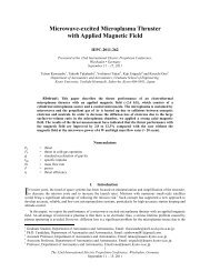
consumable anode location are shown in the schematic in Fig. 5. The thermocouple was placed on the thruster’s<br />
center axis in the middle <strong>of</strong> the center pole.<br />
Thermocouple<br />
Location<br />
Body<br />
Heater<br />
Consumable<br />
Anode<br />
Fig. 5. <strong>Thruster</strong> cross-section showing the anode, thermocouple, <strong>and</strong> resistive heater locations.<br />
The anode was heated for 60 minutes while at a 100 V potential with respect to cathode, which was grounded.<br />
Then the anode voltage was increased to 150 V to light the thruster. Once a plume was established, both resistive<br />
heaters were turned <strong>of</strong>f. The anode power supply was then current-limited rather than voltage-limited as is<br />
customary for gas-fed thrusters. The current-limited mode was used to prevent thermal runaway <strong>of</strong> the discharge: as<br />
the consumable anode became overly hot <strong>and</strong> the evaporation rate increased, the current-limited mode would cause<br />
the thruster discharge voltage to decrease <strong>and</strong> hence would reduce the thermal power to the consumable anode. In<br />
voltage-limited operation an overly hot anode would cause greater mass flow <strong>and</strong>, hence greater current. Increased<br />
current at constant voltage would increase the thermal power input to the anode <strong>and</strong> further increase the mass flow<br />
causing runaway. For most <strong>of</strong> the experiment the anode current was held at 4 or 5 A while the magnet current was<br />
constantly adjusted to maintain thruster operation. Because the voltages <strong>and</strong> currents were adjusted manually, these<br />
values varied throughout the experiment as investigators explored the criteria necessary to maintain a discharge<br />
sustained only by plasma heating. Despite open loop operation <strong>and</strong> lack <strong>of</strong> anode temperature control, it proved<br />
surprisingly easy to maintain thruster operation for more than 60 minutes, as shown in Fig. 6.<br />
The 31 st 6<br />
International Electric Propulsion Conference, University <strong>of</strong> Michigan, USA<br />
September 20 – 24, 2009<br />
Anode<br />
Heater