Development of a Magnesium and Zinc Hall-effect Thruster
Development of a Magnesium and Zinc Hall-effect Thruster
Development of a Magnesium and Zinc Hall-effect Thruster

Create successful ePaper yourself
Turn your PDF publications into a flip-book with our unique Google optimized e-Paper software.
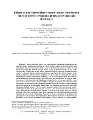
Fig. 16. <strong>Hall</strong>-<strong>effect</strong> thruster operating at 3 A <strong>of</strong> anode current <strong>and</strong> 260 V using zinc<br />
propellant with an argon cathode.<br />
C) <strong>Thruster</strong> Operation using Porous Anode<br />
After the pathfinding studies using consumable anodes demonstrated the ability to sublime sufficient propellant<br />
vapors to sustain a <strong>Hall</strong> thruster discharge, a hollow/porous anode was implemented so that investigators could<br />
perform repeated tests to explore the ability to control propellant mass flow using shim anodes. Along with the<br />
porous anode, the shims were introduced into the discharge channel to control the anode temperature, <strong>and</strong><br />
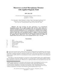
subsquently the evaporation rate <strong>of</strong> propellant. A cross section schematic <strong>of</strong> the thruster is shown in Fig. 17.<br />
Propellant<br />
Fig. 17. Cross-section schematic <strong>of</strong> the condensable propellant thruster showing<br />
the main anode <strong>and</strong> shim anode locations.<br />
The goal <strong>of</strong> the experiment using the porous main anode <strong>and</strong> shim anodes was tw<strong>of</strong>old: (1) demonstrate the<br />
ability to stabilize the main anode temperature <strong>and</strong> thus the propellant supply rate, <strong>and</strong> (2) increase/decrease the<br />
main anode temperature <strong>and</strong> propellant supply rate in a controlled manner. To accomplish this the thruster was preheated<br />
using the external body heater until the main anode temperature was approximately 450 deg. C, whereupon<br />
the body heater was turned <strong>of</strong>f <strong>and</strong> remained <strong>of</strong>f for the duration <strong>of</strong> the test. The thruster discharge was initiated by<br />
setting both the main anode power supply <strong>and</strong> the shim power supply to current-limited mode with an initial start-up<br />
voltage <strong>of</strong> 300 V on both main <strong>and</strong> shim. The current limit on the main anode was 3 A <strong>and</strong> the shim anode was 1 A.<br />
The 31 st 12<br />
International Electric Propulsion Conference, University <strong>of</strong> Michigan, USA<br />
September 20 – 24, 2009<br />
Outer<br />
Shim Anode<br />
Inner<br />
Shim Anode<br />
Main Anode<br />
Thermocouple<br />
Location