Create successful ePaper yourself
Turn your PDF publications into a flip-book with our unique Google optimized e-Paper software.
24 Bit / 192 kHz �<br />
<strong>User's</strong> <strong>Guide</strong><br />
<strong>Babyface</strong><br />
Portable USB Audio at its best!<br />
TotalMix <br />
SteadyClock SyncCheck <br />
USB 2.0 Digital I/O System<br />
22 Channels Analog / ADAT / SPDIF Interface<br />
24 Bit / 192 kHz Digital Audio<br />
20 x 12 Matrix Router<br />
MIDI I/O<br />
MIDI Remote Control
2<br />
General<br />
1 Introduction ...............................................................6<br />
2 Package Contents .....................................................6<br />
3 System Requirements ..............................................6<br />
4 Brief Description and Characteristics.....................6<br />
5 First Usage - Quick Start<br />
5.1 Connectors – Controls – Display ............................7<br />
5.2 Quick Start ..............................................................9<br />
Installation and Operation - Windows<br />
6 Hardware Installation..............................................12<br />
7 Driver and Firmware<br />
7.1 Driver Installation .....................................................12<br />
7.2 Driver Update...........................................................13<br />
7.3 De-installing the Drivers...........................................13<br />
7.4 Firmware Update .....................................................13<br />
8 Configuring the <strong>Babyface</strong><br />
8.1 Settings Dialog – General ........................................14<br />
8.2 Settings Dialog – Pitch.............................................16<br />
9 Operation and Usage<br />
9.1 Playback...................................................................17<br />
9.2 DVD Playback (AC-3 / DTS) ....................................18<br />
9.3 Notes on WDM.........................................................19<br />
9.4 Channel Count under WDM.....................................20<br />
9.5 Multi-client Operation ...............................................20<br />
9.6 Analog Recording.....................................................21<br />
9.7 Digital Recording......................................................21<br />
9.8 Digital Connections ..................................................22<br />
9.9 Clock Modes - Synchronization ...............................23<br />
10 Operation under ASIO<br />
10.1 General ................................................................24<br />
10.2 Channel Count under ASIO .................................24<br />
10.3 Known Problems..................................................25<br />
11 Using more than one <strong>Babyface</strong> .............................25<br />
12 DIGICheck Windows ...............................................26<br />
13 Hotline – Troubleshooting......................................27<br />
Installation and Operation - Mac OS X<br />
14 Hardware Installation..............................................30<br />
15 Driver and Firmware<br />
15.1 Driver Installation .................................................30<br />
15.2 Driver Update .......................................................30<br />
15.3 Firmware Update..................................................31<br />
16 Configuring the <strong>Babyface</strong><br />
16.1 Settings Dialog – General ....................................31<br />
16.2 Clock Modes - Synchronization ...........................33<br />
<strong>User's</strong> <strong>Guide</strong> <strong>Babyface</strong> © <strong>RME</strong>
17 Mac OS X FAQ<br />
17.1 Round about Driver Installation ........................... 34<br />
17.2 MIDI doesn't work ................................................ 34<br />
17.3 Repairing Disk Permissions................................. 34<br />
17.4 Supported Sample Rates..................................... 34<br />
17.5 Channel Count under Core Audio ....................... 35<br />
17.6 Various Information.............................................. 35<br />
18 Using more than one <strong>Babyface</strong> ............................. 36<br />
19 DIGICheck Mac........................................................ 36<br />
20 Hotline – Troubleshooting ..................................... 37<br />
TotalMix FX<br />
21 TotalMix: Routing and Monitoring<br />
21.1 Overview .............................................................. 40<br />
21.2 The User Interface ............................................... 42<br />
21.3 The Channel ........................................................ 43<br />
Settings.............................................................. 45<br />
Equalizer ........................................................... 46<br />
21.4 Section Control Room.......................................... 48<br />
21.5 The Control Strip.................................................. 49<br />
View Options ..................................................... 50<br />
Channel Layout ............................................. 50<br />
Scroll Location Markers................................. 51<br />
Snapshots - Groups .......................................... 52<br />
21.6 Reverb and Echo ................................................. 53<br />
21.7 Preferences.......................................................... 56<br />
21.8 Settings ................................................................ 57<br />
21.8.1 Mixer Page................................................... 57<br />
21.8.2 MIDI Page .................................................... 58<br />
21.8.3 OSC Page.................................................... 59<br />
21.9 Hotkeys and Usage ............................................. 60<br />
21.10 Menu Options....................................................... 61<br />
22 The Matrix<br />
22.1 Overview .............................................................. 62<br />
22.2 The User Interface ............................................... 62<br />
22.3 Usage...................................................................62<br />
23 Tips and Tricks<br />
23.1 ASIO Direct Monitoring (Windows)...................... 63<br />
23.2 Copy a Submix..................................................... 63<br />
23.3 Delete a Submix................................................... 63<br />
23.4 Doubling the Output Signal.................................. 63<br />
23.5 Recording a Submix - Loopback ......................... 64<br />
23.6 MS Processing..................................................... 65<br />
24 MIDI Remote Control<br />
24.1 Overview .............................................................. 66<br />
24.2 Mapping ............................................................... 66<br />
24.3 Setup.................................................................... 67<br />
24.4 Operation ............................................................. 67<br />
24.5 MIDI Control......................................................... 68<br />
24.6 Loopback Detection ............................................. 69<br />
24.7 OSC (Open Sound Control)................................. 69<br />
<strong>User's</strong> <strong>Guide</strong> <strong>Babyface</strong> © <strong>RME</strong> 3
4<br />
Technical Reference<br />
25 Technical Specifications<br />
25.1 Analog ..................................................................72<br />
25.2 MIDI......................................................................72<br />
25.3 Digital ...................................................................73<br />
25.4 Digital Inputs ........................................................73<br />
25.5 Digital Outputs......................................................73<br />
25.6 General ................................................................73<br />
26 Technical Background<br />
26.1 Lock and SyncCheck ...........................................74<br />
26.2 Latency and Monitoring........................................75<br />
26.3 USB Audio............................................................76<br />
26.4 DS – Double Speed .............................................77<br />
26.5 QS – Quad Speed................................................77<br />
26.6 Noise Level in DS / QS Mode ..............................78<br />
26.7 SteadyClock .........................................................78<br />
27 Diagrams<br />
27.1 Block Diagram <strong>Babyface</strong>......................................79<br />
27.2 Connector Pinouts................................................80<br />
Miscellaneous<br />
28 Accessories .............................................................82<br />
29 Warranty...................................................................82<br />
30 Appendix ..................................................................83<br />
31 Declaration of Conformity......................................84<br />
<strong>User's</strong> <strong>Guide</strong> <strong>Babyface</strong> © <strong>RME</strong>
<strong>User's</strong> <strong>Guide</strong><br />
<strong>Babyface</strong><br />
General<br />
<strong>User's</strong> <strong>Guide</strong> <strong>Babyface</strong> © <strong>RME</strong> 5
1. Introduction<br />
Thank you for choosing the <strong>RME</strong> <strong>Babyface</strong>. This unique audio system is capable of transferring<br />
analog and digital audio data directly to Windows and Mac computers. The latest Plug and Play<br />
technology guarantees a simple installation, even for the inexperienced user. Numerous unique<br />
features and well thought-out configuration dialog puts the <strong>Babyface</strong> at the very top of the range<br />
of computer-based audio interfaces.<br />
The package contains drivers for Windows XP / Vista / 7 and Mac OS X x86 (Intel).<br />
Our high-performance philosophy guarantees maximum system performance by executing as<br />
many functions as possible not in the driver (i.e. the CPU), but within the audio hardware.<br />
2. Package Contents<br />
• <strong>Babyface</strong><br />
• Cable USB 2.0 with double power connector<br />
• Breakout cable XLR / TRS / DIN<br />
• D-sub extension cable 1.3m (4.3 ft)<br />
• Carrying bag, grey mesh<br />
• Manual<br />
• <strong>RME</strong> Driver CD<br />
3. System Requirements<br />
• Windows XP SP2 or up, Intel Mac OS X (10.6 or up)<br />
• 1 USB 2.0 port<br />
• Computer with at least Pentium Core 2 Duo CPU<br />
4. Brief Description and Characteristics<br />
• All settings can be changed in real-time<br />
• Buffer sizes/latencies from 48 up to 8192 samples selectable<br />
• 4 channels 96 kHz/24 bit Record/Playback via ADAT optical (S/MUX)<br />
• Clock modes slave and master<br />
• Automatic and intelligent master/slave clock control<br />
• Unsurpassed Bitclock PLL (audio synchronization) in ADAT mode<br />
• SteadyClock: Jitter-immune, super-stable digital clock<br />
• DDS technology for free setting of the sample rate<br />
• SyncAlign guarantees sample aligned and never swapping channels<br />
• SyncCheck tests and reports the synchronization status of input signals<br />
• TotalMix for latency-free submixes and perfect ASIO Direct Monitoring<br />
• TotalMix: 264 channel mixer with 46 bit internal resolution<br />
• TotalMix FX: 3-band EQ, Low Cut, Reverb, Echo<br />
• 1 x MIDI I/O, 16 channels high-speed MIDI<br />
• 2 digitally controlled microphone inputs in reference quality<br />
• 2 balanced line outputs, level +15 dBu<br />
• 1 x headphone output<br />
• DIGICheck DSP: Level meter in hardware, peak- and RMS calculation<br />
6<br />
<strong>User's</strong> <strong>Guide</strong> <strong>Babyface</strong> © <strong>RME</strong>
5. First Usage – Quick Start<br />
5.1 Connectors – Controls – Display<br />
The top of the <strong>Babyface</strong> features a rotary encoder with push switch function, 2 keys, 2 LED<br />
bands and 5 status LEDs.<br />
The two LED bands show the current gain, the input or output level, or indicate the channel to<br />
be set, all dependent on the current mode. The lowest LED signals phantom power (+48 V,<br />
orange), the highest one overload (Clip, red).<br />
The rotary encoder is used to change various parameters directly at the unit. First the left key<br />
Select is used to select the mode which is then displayed by the Status LEDs:<br />
� Input: Setting the gain of the analog stereo inputs. A<br />
push on the encoder changes between left, right or<br />
both.<br />
� Output: Setting the output level of the analog outputs<br />
1/2 at the breakout cable. A push on the encoder<br />
activates Dim for the Main Out defined in TotalMix FX<br />
(default: Analog 1/2).<br />
� Phones: Setting the output levels of the analog<br />
outputs 3/4. A push on the encoder activates Dim for<br />
the Main Out defined in TotalMix FX (default: Analog<br />
1/2).<br />
� Sync: Synchronisation indicator for the digital optical<br />
input (SPDIF, ADAT). Flashes when the signal has<br />
been detected but is not fully synchronous. See also<br />
chapter 9.9 / 16.2, Clock Modes - Synchronisation.<br />
The key Recall is used to store and load a specific listening volume for the Main Out (default:<br />
Analog 1/2) defined in TotalMix FX. Pushing the knob for 2 seconds stores the current setting. If<br />
the volume (output level) had been changed a quick hit on the Recall key will restore the former<br />
value.<br />
The right side of the <strong>Babyface</strong> has an instrument input and a<br />
headphones output.<br />
The analog input 2 can be switched in TotalMix between line (low<br />
impedance, balanced, at the breakout cable) and instrument (high<br />
impedance, unbalanced, TRS jack at the unit). See Settings menu<br />
of input channel 2.<br />
The analog outputs Phones (channels 3/4) are available at the breakout cable and on the right<br />
side of the unit. The connectors are not separated electrically. When connecting two headphones<br />
the volume might be reduced. The low impedance and unbalanced output signal is – in<br />
terms of quality – identical to the ones at the line outputs, but limited to +7 dBu.<br />
In case the phones output is to be used as line output, usually an adapter TRS plug to RCA<br />
phono plugs, or TRS plug to TS plugs is required. More on cable codes and pinouts can be<br />
found in chapter 27.2.<br />
<strong>User's</strong> <strong>Guide</strong> <strong>Babyface</strong> © <strong>RME</strong> 7
8<br />
The short circuit protected, low impedance line outputs do not operate servo balanced!<br />
When connecting unbalanced equipment, make sure pin 3 of the XLR output is not connected.<br />
A connection to ground will cause a decreased THD (higher distortion) and increased<br />
power consumption!<br />
The <strong>Babyface</strong> has two analog microphone inputs that can operate as line inputs with levels up<br />
to +12 dBu, when set to 0 dB gain. The electronic input stage uses a servo balanced design<br />
which handles unbalanced and balanced signals correctly, automatically adjusting the level<br />
reference.<br />
When using unbalanced cables with the XLR breakout cable: be sure to connect the 'ring'<br />
contact of a stereo TRS jack, and pin 3 of a XLR jack, to ground. Otherwise noise may occur,<br />
caused by the unconnected negative input of the balanced input.<br />
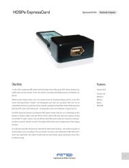
The rear of the <strong>Babyface</strong> has an<br />
optical input and output, a power<br />
supply connector, a USB socket<br />
and a 15-pin D-sub connector for<br />
the included breakout cable.<br />
Optical Out USB 2.0<br />
Breakout cable Optical In Power<br />
Optical I/O (TOSLINK): The unit automatically detects SPDIF or ADAT input signals. The optical<br />
output can operate as ADAT or SPDIF output, depending on the current setting in the Settings<br />
dialog.<br />
USB 2.0: USB socket for connection to the computer.<br />
Socket for power connection. Unburdens the computer’s power supply, or ensures a stable<br />
power supply, in case it proves to be insufficient when taken from the computer. If the power<br />
supply via standard USB cables is not sufficient the included special dual power cable can also<br />
be used.<br />
The included breakout cable provides these connections:<br />
� Microphone/Line In: 2 x XLR, balanced<br />
� Line Out: 2 x XLR, balanced<br />
� Phones Output: 1 x stereo TRS 1/4"<br />
(6.3 mm), unbalanced. Can also be<br />
used as additional line output.<br />
� MIDI I/O: One MIDI input and output via 5-pin DIN connector.<br />
If the breakout cable turns your desktop into a mess the included extension cable comes to the<br />
rescue. It is simply inserted between the breakout cable and the D-sub connector of the <strong>Babyface</strong>.<br />
Then both breakout cable and all cables connected to it will be out of sight, without decreasing<br />
the <strong>Babyface</strong>’s technical specifications or performance.<br />
<strong>User's</strong> <strong>Guide</strong> <strong>Babyface</strong> © <strong>RME</strong>
5.2 Quick Start<br />
After the driver installation (chapter 7 / 15), connect the inputs to the analog signal source.<br />
Mount the included breakout cable with or without the extension cable to the D-sub connector of<br />
the <strong>Babyface</strong>.<br />
The analog input sensitivity can be changed at the unit (Select In) or in TotalMix (Settings,<br />
Gain), assuring the highest signal to noise ratio will be achieved. Also try to achieve an optimum<br />
input level by adjusting the source itself. Raise the source’s output level until the peak level<br />
meters in TotalMix reach about –3 dB.<br />
The analog line inputs of the <strong>Babyface</strong> can be used with +4 dBu and -10 dBV signals. The electronic<br />
input stage can handle balanced (XLR, TRS jacks) and unbalanced (TS jacks) input signals<br />
correctly.<br />
The <strong>Babyface</strong>'s digital output supports the formats SPDIF and ADAT optical.<br />
On the analog playback side (the DA side), an adjustment of the analog output level can be<br />
done by the rotary encoder (Select Out or Phones), or in TotalMix FX.<br />
The output signal of channels 3/4, Phones, is also available at the unit. The output level can be<br />
set freely using the rotary encoder. This output is a low impedance type, which can also be<br />
used to connect headphones.<br />
TotalMix FX remembers all settings, and loads these automatically when the <strong>Babyface</strong> drivers<br />
are loaded.<br />
<strong>User's</strong> <strong>Guide</strong> <strong>Babyface</strong> © <strong>RME</strong> 9
10<br />
<strong>User's</strong> <strong>Guide</strong> <strong>Babyface</strong> © <strong>RME</strong>
<strong>User's</strong> <strong>Guide</strong><br />
<strong>Babyface</strong><br />
Installation and Operation – Windows<br />
<strong>User's</strong> <strong>Guide</strong> <strong>Babyface</strong> © <strong>RME</strong> 11
6. Hardware Installation<br />
Connect computer and <strong>Babyface</strong> with the supplied USB cable. Turn on the computer. That‘s it.<br />
Chapter 26.3 explains how to find the ideal USB port.<br />
7. Driver and Firmware<br />
7.1 Driver Installation<br />
After the <strong>Babyface</strong> has been recognized, (see 6. Hardware Installation) the hardware assistant<br />
finds a <strong>Babyface</strong>. Insert the <strong>RME</strong> Driver CD into your CD-ROM drive, and follow further instructions<br />
which appear on your computer screen. The driver files are located in the directory<br />
\<strong>Babyface</strong> on the <strong>RME</strong> Driver CD.<br />
Windows now installs the driver of the <strong>Babyface</strong> and<br />
registers it as a new audio device in the system. After a<br />
reboot, the symbols of TotalMix and Settings dialog will<br />
appear in the task bar.<br />
12<br />
In case the Hardware Wizard does not show up automatically after connecting the <strong>Babyface</strong>,<br />
do not attempt to install the drivers manually! An installation of drivers for nonrecognized<br />
hardware can cause a blue screen when booting Windows!<br />
In Windows 7 Microsoft removed the automatic start of the Driver Software Update dialog. Therefore<br />
this dialog has to be started manually after the failed driver installation. Hit the Windows<br />
key, type 'Device Manager', start the Device Manager by selecting it from the list and hit Enter.<br />
The device is shown with a yellow warning symbol. Usually it is already found in the correct<br />
category, Sound, Video and Game Controller (Plug & Play detects a multimedia device). Right<br />
click on the device and select 'Update Driver Software' from the context menu.<br />
The dialog Update Driver Software appears. Now follow the instructions given below.<br />
Possible reasons why a <strong>Babyface</strong> is not found automatically:<br />
• The USB port is not active in the system (check the Device Manager)<br />
• The USB cable is not, or not correctly inserted into the socket<br />
• The <strong>Babyface</strong> does not receive any or not enough power. In this case please use the included<br />
dual cable. Plug both connectors from one end of the cable into the computer. If the<br />
<strong>Babyface</strong> starts correctly the lowest green LED in the left band will flash, the In LED is constantly<br />
lit, the lowest one in the right band too.<br />
<strong>User's</strong> <strong>Guide</strong> <strong>Babyface</strong> © <strong>RME</strong>
7.2 Driver Update<br />
When facing problems with the automatic driver update, the user-driven way of driver installation<br />
will work.<br />
Under >Control Panel /System /Device Manager /Sound, Video and Game Controllers /<strong>RME</strong><br />
<strong>Babyface</strong>/Properties /Driver< you'll find the 'Update Driver' button.<br />
XP: Select 'Install from a list or specific location (advanced)', click 'Next', select 'Don't<br />
search I will choose the driver to install', click 'Next', then 'Have Disk'. Now point to the<br />
driver update's directory.<br />
Vista/7: Select 'Browse my computer for driver software', then 'Let me pick from a list of<br />
device drivers from my computer', then 'Have Disk'. Now point to the driver update's directory.<br />
This method also allows for the installation of older drivers than the currently installed ones.<br />
7.3 De-installing the Drivers<br />
A de-installation of the driver files is not necessary – and not supported by Windows anyway.<br />
Thanks to full Plug & Play support, the driver files will not be loaded after the hardware has<br />
been removed. If desired these files can then be deleted manually.<br />
Unfortunately Windows Plug & Play methods do not cover the additional autorun entries of TotalMix,<br />
the Settings dialog, and the registration of the ASIO driver. These entries can be removed<br />
from the registry by a software de-installation request. This request can be found (like all<br />
de-installation entries) in Control Panel, Add or Remove Programs (Vista/7: Programs and Features).<br />
Click on the entry '<strong>RME</strong> Fireface USB'.<br />
7.4 Firmware Update<br />
The Flash Update Tool updates the firmware of the <strong>Babyface</strong> to the latest version. It requires an<br />
already installed driver.<br />
Start the program fut_usb.exe. The Flash Update<br />
Tool displays the current revision of the <strong>Babyface</strong>'s<br />
firmware, and whether it needs an update or not. If<br />
so, then simply press the 'Update' button. A<br />
progress bar will indicate when the flash process is<br />
finished (Verify Ok).<br />
After the update the <strong>Babyface</strong> needs to be reset.<br />
This is done by powering down the <strong>Babyface</strong> for a<br />
short time.<br />
Attention: the <strong>Babyface</strong> should not be switched off<br />
for less than 5 seconds, because Windows<br />
completely unloads the driver, which takes some<br />
time to finish.<br />
A reboot of the computer is not necessary.<br />
When the update fails (status: failure), the unit's Safety BIOS will be used from the next boot on,<br />
the unit stays fully functional. The flash process should then be tried again.<br />
<strong>User's</strong> <strong>Guide</strong> <strong>Babyface</strong> © <strong>RME</strong> 13
8. Configuring the <strong>Babyface</strong><br />
8.1 Settings Dialog - General<br />
Configuration of the <strong>Babyface</strong> is done via its own settings dialog. The panel 'Settings' can be<br />
opened:<br />
• by clicking on the fire symbol in the Task Bar's notification area<br />
The mixer of the <strong>Babyface</strong> (TotalMix) can be opened:<br />
• by clicking on the double arrow symbol in the Task Bar's notification area<br />
The hardware of the <strong>Babyface</strong> offers a number of helpful, well thought-out practical functions<br />
and options which affect how the card operates - it can be configured to suit many different<br />
requirements.<br />
The following is available in the Settings dialog:<br />
• Latency<br />
• Operation of the DSP<br />
• Configuration of the digital I/O<br />
• Current sample rate<br />
• Synchronization behaviour<br />
• State of input and output<br />
Any changes made in the<br />
Settings dialog are applied<br />
immediately - confirmation (e.g.<br />
by clicking on OK or exiting the<br />
dialog) is not required.<br />
However, settings should not be<br />
changed during playback or<br />
record if it can be avoided, as<br />
this can cause unwanted noises.<br />
Also, please note that even in<br />
'Stop' mode, several programs<br />
keep the recording and playback<br />
devices open, which means that<br />
any new settings might not be<br />
applied immediately.<br />
14<br />
<strong>User's</strong> <strong>Guide</strong> <strong>Babyface</strong> © <strong>RME</strong>
Buffer Size<br />
The setting Buffer Size determines the latency between incoming and outgoing ASIO and WDM<br />
data, as well as affecting system stability (see chapter 9.1 / 10).<br />
Errors does not refer to buffer errors, but USB transmission errors. The display will be reset on<br />
any start of a playback/record. More information can be found in chapter 26.3.<br />
Options<br />
DSP – EQ for Record<br />
Switches the 3-band EQ and Low Cut of all input channels into the recording path. In case<br />
Loopback has been activated the EQ and Low Cut of the Output channel is placed into the recording<br />
path. See also chapter 23.5.<br />
Optical Out<br />
The optical TOSLINK output can operate as ADAT or SPDIF output. The Channel Status is<br />
fixed to Consumer state.<br />
Note: The optical input detects the incoming format automatically.<br />
SPDIF In<br />
TMS activates the transmission of Channel Status data and Track Marker information from the<br />
SPDIF input signal.<br />
Clock Mode<br />
Sample Rate<br />
Sets the currently used sample rate. Offers a central and comfortable way of configuring the<br />
sample rate of all WDM devices to the same value, as since Vista the audio software is no<br />
longer allowed to set the sample rate. However, an ASIO program can still set the sample rate<br />
by itself.<br />
During record/playback the selection is greyed out, so no change is possible.<br />
Clock Source<br />
The unit can be configured to use its own clock (Internal = Master) or the digital input signal<br />
(Optical = Slave). If the external source isn't available (Input Status No Lock), the unit will<br />
change to the internal clock. The current clock source is displayed as Current.<br />
Pitch<br />
More information on Pitch is available in chapter 8.2.<br />
Input Status<br />
Indicates presence of a valid signal at the optical input (Lock, No Lock) and whether the signal<br />
is synchronous (Sync). The third column shows the sample frequency detected by the hardware<br />
(coarse recognition, 32 kHz, 44.1 kHz, 48 kHz etc.). In Clock Mode the clock reference is<br />
shown. See also chapter 26.1.<br />
The About tab includes information about the current driver version as well as the current firmware<br />
version of the <strong>Babyface</strong>.<br />
<strong>User's</strong> <strong>Guide</strong> <strong>Babyface</strong> © <strong>RME</strong> 15
8.2 Settings Dialog - Pitch<br />
Usually soundcards and audio interfaces generate their internal clock (master mode) by a<br />
quartz. Therefore the internal clock can be set to 44.1 kHz or 48 kHz, but not to a value in between.<br />
SteadyClock, <strong>RME</strong>'s sensational Low Jitter Clock System, is based on a Direct Digital<br />
Synthesizer (DDS). This superior circuitry can generate nearly any frequency with highest precision.<br />
DDS has been implemented into the <strong>Babyface</strong> with regard to the needs of professional video<br />
applications, as well as to maximum flexibility. The section Pitch includes both a list of typical<br />
video frequencies (so called pull up/pull down at 0.1% and 4%) and a fader to freely change the<br />
basic sample rate in steps of 1 Hz (!) over a range of +/- 5%.<br />
16<br />
The Pitch function requires the <strong>Babyface</strong> to be in clock mode Master (Internal)! The frequency<br />
setting will only be applied to this one specific <strong>Babyface</strong>!<br />
Changing the sample rate during record/playback often results in a loss of audio, or brings<br />
up warning messages of the audio software. Therefore the desired sample rate should be<br />
set at least coarsely before starting the software.<br />
Coarse<br />
Coarse modification in steps of 50 Hz<br />
is done by clicking with the mouse to<br />
the left and right of the fader knob.<br />
Fine<br />
Fine modification in steps of 1 Hz is<br />
done by using the left/right cursor<br />
keys.<br />
Reset<br />
Ctrl key plus left mouse click.<br />
Application examples<br />
Pitch allows for a simultaneous change of speed and tune during record and playback. From<br />
alignment to other sources up to creative effects – everything is possible.<br />
Pitch enables you to intentionally de-tune the complete DAW. This way, the DAW can match<br />
instruments which have a wrong or unchangeable tuning.<br />
Pitch allows for the change of the sample rate of all WDM devices at the same time. Since Vista<br />
this is no longer possible via the audio program, thus requires a manual reconfiguration of all<br />
WDM devices. Changing the sample rate from the Settings dialog solves this problem. As the<br />
change within the system requires some time, record/playback should not be started immediately,<br />
but only after at least 5 seconds after a change.<br />
Tip: the current CPU load can be used to determine if the audio subsystem has finished the reconfiguration.<br />
<strong>User's</strong> <strong>Guide</strong> <strong>Babyface</strong> © <strong>RME</strong>
9. Operation and Usage<br />
9.1 Playback<br />
In the audio application being used, <strong>Babyface</strong> must be selected as output device. It can often<br />
be found in the Options, Preferences or Settings menus, as Playback Device, Audio Devices,<br />
Audio etc.<br />
We recommend switching all system sounds off (via >Control Panel /SoundControl Panel /Multimedia /Audio< or >Control Panel /Sound /Playback
9.2 DVD-Playback (AC-3/DTS)<br />
AC-3 / DTS<br />
When using popular DVD software players like WinDVD and PowerDVD, their audio data<br />
stream can be sent to any AC-3/DTS capable receiver using the <strong>Babyface</strong>'s SPDIF output. For<br />
this to work, the WDM SPDIF device of the <strong>Babyface</strong> has to be selected in >Control Panel/<br />
Sounds and Multimedia/ Audio< or >Control Panel/ Sound/PlaybackControl Panel/ Sounds and Multimedia/ AudioVolume/ Speaker Settings/ Advanced< has to<br />
be changed from Stereo to 5.1 Surround.<br />
Vista/7: >Control Panel/ Sound/ Playback < as ‘Standard’. Additionally the loudspeaker setup,<br />
found under >Configuration
9.3 Notes on WDM<br />
The driver offers one WDM streaming device per stereo pair, like Analog 3+4 (<strong>Babyface</strong>).<br />
WDM Streaming is Microsoft's current driver and audio system, directly embedded into the operating<br />
system. WDM Streaming is hardly usable for professional music purposes, as all data is<br />
processed by the so called Kernel Mixer, causing a latency of at least 30 ms. Additionally, WDM<br />
can perform sample rate conversions unnoticed, cause offsets between record and playback<br />
data, block channels unintentionally and much more.<br />
Several programs do not offer any direct device selection. Instead they use the playback device<br />
selected in Windows under<br />
XP: <br />
Vista/7: <br />
The program Sonar from Cakewalk is unique in many ways. Sonar uses the so called WDM<br />
Kernel Streaming, bypassing the WDM mixer, thus achieves a similar performance to ASIO<br />
(see below).<br />
Because of the driver's multichannel streaming ability, Sonar not only finds the stereo device<br />
mentioned above, but also the 8-channel interleaved devices, and adds the channel number at<br />
the end:<br />
<strong>Babyface</strong> Analog (1+2) 1/2 is the first stereo device<br />
<strong>Babyface</strong> Analog (3+4) is the next stereo device<br />
<strong>Babyface</strong> Analog (1+2) 3/4 are the channels 3/4 of the first 8-channel interleaved device.<br />
It is not recommended to use these special interleaved devices. Also it is not possible to use<br />
one stereo channel twice (the basic and the interleaved device).<br />
Multi-Channel using WDM<br />
The WDM Streaming device Loudspeaker (Analog 1+2) of the <strong>RME</strong> driver can operate as usual<br />
stereo device, or as up to 8-channel device.<br />
An 8-channel playback using the Windows Media Player requires the speaker setup 7.1 Surround.<br />
Configure as follows:<br />
XP: >Control Panel /Sounds and Multimedia /Audio /Volume /Speaker Settings /Advanced <<br />
Vista/7: >Control Panel /Sound /Playback /Loudspeaker /Configure <<br />
<strong>User's</strong> <strong>Guide</strong> <strong>Babyface</strong> © <strong>RME</strong> 19
9.4 Channel Count under WDM<br />
The <strong>Babyface</strong>’s ADAT optical interface offers sample rates of up to 192 kHz using a standard<br />
ADAT recorder. For this to work single-channel data is spread to two or four ADAT channels<br />
using the Sample Multiplexing technique. This reduces the number of available ADAT channels<br />
from 8 to 4 or 2 per ADAT port.<br />
Whenever the <strong>Babyface</strong> changes into Double Speed (88.2/96 kHz) or Quad Speed mode<br />
(176.4/192 kHz) all devices no longer available vanish automatically.<br />
WDM Stereo device Double Speed Quad Speed<br />
<strong>Babyface</strong> Analog (1+2) <strong>Babyface</strong> Analog (1+2) <strong>Babyface</strong> Analog (1+2)<br />
<strong>Babyface</strong> Analog (3+4) <strong>Babyface</strong> Analog (3+4) <strong>Babyface</strong> Analog (3+4)<br />
<strong>Babyface</strong> AS (1+2) <strong>Babyface</strong> AS (1+2) <strong>Babyface</strong> AS (1+2)<br />
<strong>Babyface</strong> ADAT (3+4) <strong>Babyface</strong> ADAT (3+4) <strong>Babyface</strong> ADAT (3+4)<br />
<strong>Babyface</strong> ADAT (5+6) <strong>Babyface</strong> ADAT (5+6) <strong>Babyface</strong> ADAT (5+6)<br />
<strong>Babyface</strong> ADAT (7+8) <strong>Babyface</strong> ADAT (7+8) <strong>Babyface</strong> ADAT (7+8)<br />
Note: Under Vista/7 the analog outputs 1/2 show up as Loudspeaker.<br />
9.5 Multi-client Operation<br />
<strong>RME</strong> audio interfaces support multi-client operation. Several programs can be used at the same<br />
time. Since driver version 0.981 the formats ASIO and WDM can even be used on the same<br />
playback channels simultaneously. As WDM uses a real-time sample rate conversion (ASIO<br />
does not), all active ASIO software has to use the same sample rate.<br />
However, a better overview is maintained by using the channels exclusively. This is no limitation<br />
at all, because TotalMix allows for any output routing, and therefore a playback of multiple software<br />
on the same hardware outputs.<br />
Inputs can be used from an unlimited number of WDM and ASIO software at the same time, as<br />
the driver simply sends the data to all applications simultaneously.<br />
<strong>RME</strong>'s sophisticated tool DIGICheck is an exception to this rule. It operates like an ASIO host,<br />
using a special technique to access playback channels directly. Therefore DIGICheck is able to<br />
analyse and display playback data from any software, no matter which format it uses.<br />
20<br />
<strong>User's</strong> <strong>Guide</strong> <strong>Babyface</strong> © <strong>RME</strong>
9.6 Analog Recording<br />
For recordings via the analog inputs the corresponding record device has to be chosen (<strong>Babyface</strong><br />
Analog (x+x)).<br />
Channels 1 and 2 of the <strong>Babyface</strong> have digitally controlled microphone<br />
preamps of the highest quality. The digital control offers a gain setting in<br />
steps of 3 dB within a range of 9 dB to 60 dB. The configuration is done<br />
either directly at the unit via the rotary encoder, or via the Settings panel<br />
of the input channels 1 and 2 in TotalMix, with the knob Gain. The<br />
current gain is displayed in dB beside the knob.<br />
In the lower range the knob jumps from 9 dB to 0 dB. This useful<br />
additional setting provides line signal compatibility at up to +12 dBu at<br />
the microphone input.<br />
Above the knob Gain the inputs can be set separately to provide 48V<br />
phantom power at the XLR connectors. Phantom power is required for<br />
condenser microphones.<br />
Input channel 2 can be switched to the TRS jack on the right side of the<br />
<strong>Babyface</strong>. The Hi-Z instrument input has an input impedance of 470<br />
kOhm. The input gain is controlled by the same knob, but the gain range<br />
now starts at +9 dB.<br />
It often makes sense to monitor the input signal or send it directly to the output. This can be<br />
done at zero latency using TotalMix (see chapter 21).<br />
An automated control of real-time monitoring can be achieved by Steinberg’s ASIO protocol<br />
with <strong>RME</strong>’s ASIO drivers and any ASIO 2.0 compatible program. When 'ASIO Direct Monitoring'<br />
has been switched on, the input signal is routed in real-time to the output whenever a recording<br />
is started (punch-in).<br />
9.7 Digital Recording<br />
Unlike analog soundcards which produce empty wave files (or noise) when no input signal is<br />
present, digital interfaces always need a valid input signal to start recording.<br />
Taking this into account, <strong>RME</strong> added a<br />
comprehensive I/O signal status display to<br />
the <strong>Babyface</strong>, showing sample frequency,<br />
lock and sync status in the Settings dialog,<br />
and a status LED directly at the unit.<br />
The sample frequency shown in the Settings<br />
dialog is useful as a quick display of the<br />
current configuration of the unit and the<br />
connected external equipment. If no sample<br />
frequency is recognized, it will read ‘No Lock’.<br />
This way, configuring any suitable audio application for digital recording is simple. After connection<br />
the <strong>Babyface</strong> displays the current and external sample frequency. This parameter can then<br />
be changed in the application’s audio attributes (or similar) dialog.<br />
<strong>User's</strong> <strong>Guide</strong> <strong>Babyface</strong> © <strong>RME</strong> 21
9.8 Digital Connections<br />
ADAT<br />
The ADAT optical input of the <strong>Babyface</strong> is fully compatible with all ADAT optical outputs. <strong>RME</strong>'s<br />
unsurpassed Bitclock PLL prevents clicks and drop outs even in extreme varipitch operation,<br />
and guarantees a fast and low jitter lock to the digital input signal. A usual TOSLINK cable is<br />
sufficient for connection. More information on Double Speed (S/MUX) can be found in chapter<br />
26.4.<br />
ADAT In<br />
Interface for a device sending an ADAT signal to the <strong>Babyface</strong>. Carries the channels 1 to 8.<br />
When receiving a Double Speed signal, this input carries the channels 1 to 4, at Quad Speed<br />
the inputs 1 and 2.<br />
ADAT Out<br />
Interface for a device receiving an ADAT signal from the <strong>Babyface</strong>. Transmits channels 1 to 8.<br />
When sending a Double Speed signal, this port carries channels 1 to 4, at Quad Speed the<br />
channels 1 and 2.<br />
Note: To use the optical output as ADAT port set the option Optical to ADAT in the Settings<br />
dialog.<br />
SPDIF<br />
The optical input automatically switches to SPDIF operation when such a signal is detected.<br />
The audio information is then shown in TotalMix on the first two ADAT channels, AS 1 and AS<br />
2.<br />
Activating the option TMS in the Windows Settings dialog enables <strong>RME</strong>’s DIGICheck to analyze<br />
the Channel Status of the input signal.<br />
To send out SPDIF from the optical output, select the option Optical – SPDIF in the Settings<br />
dialog. The output signal in TotalMix has to be present on the first ADAT channels, AS 1+2.<br />
MIDI<br />
<strong>Babyface</strong> offers one MIDI I/O via two 5-pin DIN jacks. The MIDI ports are added to the system<br />
by the driver. Using MIDI capable software, these ports can be accessed under the name <strong>Babyface</strong><br />
Midi. Using more than one <strong>Babyface</strong>, the operating system adds a consecutive number to<br />
the port name, like <strong>Babyface</strong> MIDI (2) etc.<br />
The MIDI ports support multi-client operation. A MIDI input signal can be received from several<br />
programs at the same time. Even the MIDI output can be used by multiple programs simultaneously.<br />
However, due to the limited bandwidth of MIDI, this kind of application will often show<br />
various problems.<br />
22<br />
<strong>User's</strong> <strong>Guide</strong> <strong>Babyface</strong> © <strong>RME</strong>
9.9 Clock Modes - Synchronization<br />
In the digital world, all devices must be either Master (clock source) or Slave (clock receiver).<br />
Whenever several devices are linked within a system, there must always be a single master<br />
clock.<br />
A digital system can only have one master! If the <strong>Babyface</strong>’s clock mode is set to 'Internal',<br />
all other devices must be set to ‘Slave’.<br />
The <strong>Babyface</strong> utilizes a very user-friendly, intelligent clock control, called AutoSync. Selecting<br />
Optical as Clock Source, the system constantly scans the digital input for a valid signal. If any<br />
valid signal is found, the <strong>Babyface</strong> switches from the internal quartz (Clock Mode – Current<br />
Internal) to a clock extracted from the input signal (Clock Mode – Current ADAT or SPDIF). The<br />
difference to a usual slave mode is that whenever the clock reference fails, the system will<br />
automatically use its internal clock and operate in clock mode Master.<br />
AutoSync guarantees that record and record-while-play will always work correctly. In certain<br />
cases however, e.g. when the inputs and outputs of a DAT machine are connected directly to<br />
the <strong>Babyface</strong>, AutoSync may cause feedback in the digital carrier, so synchronization breaks<br />
down. To solve this problem switch the <strong>Babyface</strong> clock mode to Master (Clock Source – Internal).<br />
In some situations changing the clock mode can not be avoided. Example: A CD player is connected<br />
to the SPDIF input. Try recording a few samples from the CD and you will be disappointed<br />
- few CD players can be synchronized. The samples will inevitably be corrupted, because<br />
the signal from the CD player is read with the clock from the <strong>Babyface</strong>, being out of sync.<br />
In this case, the Clock Source should be set temporarily to SPDIF.<br />
<strong>RME</strong>’s exclusive SyncCheck technology (first implemented in the Hammerfall) enables an easy<br />
to use check and display of the current clock status. Input Status indicates whether there is a<br />
valid signal (Lock, No Lock) for the optical input, or if there is a valid and synchronous signal<br />
(Sync). In the field Clock Mode the clock reference is shown. See chapter 26.1.<br />
Under WDM the <strong>Babyface</strong> will (has<br />
to) set the sample rate. Therefore the<br />
error shown to the right can occur. A<br />
stable signal with a sample rate of 32<br />
kHz is detected at the ADAT input<br />
(Sync), but Windows audio had been<br />
set to 44100 Hz before. The red color<br />
of the text label signals the error<br />
condition, and prompts the user to set<br />
32000 Hz manually as sample rate.<br />
Under ASIO the audio software sets<br />
the sample rate, so that such an error<br />
can not happen. If the input sample<br />
rate is different then there will be no<br />
Sync indication.<br />
With <strong>RME</strong>’s AutoSync and SyncCheck, finally anyone can master this common source of error,<br />
previously one of the most complex issues in the digital studio world.<br />
<strong>User's</strong> <strong>Guide</strong> <strong>Babyface</strong> © <strong>RME</strong> 23
10. Operation under ASIO<br />
10.1 General<br />
Start the ASIO software and select ASIO Fireface USB as the audio I/O device or the audio<br />
driver.<br />
The <strong>Babyface</strong> supports ASIO Direct Monitoring (ADM).<br />
The <strong>Babyface</strong> MIDI I/O can be used with both MME MIDI and DirectMusic MIDI.<br />
10.2 Channel Count under ASIO<br />
At a sample rate of 88.2 or 96 kHz, the ADAT optical input and output operates in S/MUX mode,<br />
so the number of available channels is reduced from 8 to 4.<br />
At a sample rate of 176.4 and 192 kHz, the ADAT optical input and output operates in S/MUX4<br />
mode, so the number of available channels is limited to 2.<br />
Note: When changing the sample rate range between Single, Double and Quad Speed the<br />
number of channels presented from the ASIO driver will change too. This may require a reset of<br />
the I/O list in the audio software.<br />
Single Speed Double Speed Quad Speed<br />
<strong>Babyface</strong> Analog 1 to 4 <strong>Babyface</strong> Analog 1 to 4 <strong>Babyface</strong> Analog 1 to 4<br />
<strong>Babyface</strong> AS 1 to 2 <strong>Babyface</strong> AS 1 to 2 <strong>Babyface</strong> AS 1 to 2<br />
<strong>Babyface</strong> ADAT 3 to 4 <strong>Babyface</strong> ADAT 3 to 4 <strong>Babyface</strong> ADAT 3 to 4<br />
<strong>Babyface</strong> ADAT 5 to 6 <strong>Babyface</strong> ADAT 5 to 6 <strong>Babyface</strong> ADAT 5 to 6<br />
<strong>Babyface</strong> ADAT 7 to 8 <strong>Babyface</strong> ADAT 7 to 8 <strong>Babyface</strong> ADAT 7 to 8<br />
24<br />
<strong>User's</strong> <strong>Guide</strong> <strong>Babyface</strong> © <strong>RME</strong>
10.3 Known Problems<br />
If a computer does not provide sufficient CPU-power and/or sufficient USB-bus transfer rates,<br />
then drop outs, crackling and noise will appear. Such effects can be avoided by using a higher<br />
buffer setting/latency in the Settings dialog of the <strong>Babyface</strong>. Furthermore PlugIns should be<br />
deactivated temporarily to make sure they do not cause these problems.<br />
More information can be found in chapter 26.3.<br />
Another common source of trouble is incorrect synchronization. ASIO does not support asynchronous<br />
operation, which means that the input and output signals not only have to use the<br />
same sample frequency, but also have to be in sync. All devices connected to the <strong>Babyface</strong><br />
must be properly configured for Full Duplex operation. As long as SyncCheck (in the Settings<br />
dialog) only displays Lock instead of Sync, the devices have not been set up properly!<br />
The same applies when using more than one <strong>Babyface</strong> or Fireface UC - they all have to be in<br />
sync. Else a periodically repeated noise will be heard.<br />
The <strong>Babyface</strong> supports ASIO Direct Monitoring (ADM). Please note that not all programs support<br />
ADM completely or error-free. The most often reported problem is the wrong behaviour of<br />
panorama in a stereo channel.<br />
In case of a drift between audio and MIDI, or in case of a fixed deviation (MIDI notes placed<br />
close before or behind the correct position), the settings in Cubase/Nuendo have to be<br />
changed. At the time of print the option 'Use System Timestamp' should be activated. The<br />
<strong>Babyface</strong> supports both MME MIDI and DirectMusic MIDI. It depends on the used application<br />
which one will work better.<br />
11. Using more than one <strong>Babyface</strong><br />
The current driver supports up to three <strong>Babyface</strong> or Fireface UC. All units have to be in sync,<br />
i.e. have to receive valid digital sync information.<br />
• If one of the <strong>Babyface</strong>s is set to clock mode Master, all others have to be set to clock mode<br />
Slave, and have to be synced from the master, for example by feeding word clock. The<br />
clock modes of all units have to be set up correctly in the <strong>Babyface</strong> Settings dialog.<br />
• If all units are fed with a synchronous clock, i.e. all units show Sync in their Settings dialog,<br />
all channels can be used at once. This is especially easy to handle under ASIO, as the<br />
ASIO driver presents all units as one.<br />
Note: TotalMix is part of the hardware of each <strong>Babyface</strong>. Up to three mixers are available, but<br />
these are separated and can't interchange data. Therefore a global mixer for all units is not<br />
possible.<br />
In real-world an operation of more than one <strong>Babyface</strong> makes no sense and is therefore not<br />
actively supported by <strong>RME</strong>. The second unit would have to be synchronized using the optical<br />
input. The result is an extension by only 2 analog record and 4 analog playback channels (plus 8<br />
digital via ADAT Out). It makes much more sense to directly connect an 8-channel converter to<br />
the ADAT I/O of one <strong>Babyface</strong>, adding full 8 channels of record and playback.<br />
<strong>User's</strong> <strong>Guide</strong> <strong>Babyface</strong> © <strong>RME</strong> 25
12. DIGICheck Windows<br />
The DIGICheck software is a unique utility developed for testing, measuring and analysing digital<br />
audio streams. Although this Windows software is fairly self-explanatory, it still includes a<br />
comprehensive online help. DIGICheck 5.3 operates as multi-client ASIO host, therefore can be<br />
used in parallel to any software, with both inputs and outputs (!). The following is a short summary<br />
of the currently available functions:<br />
• Level Meter. High precision 24-bit resolution, 2/10/28 channels. Application examples: Peak<br />
level measurement, RMS level measurement, over-detection, phase correlation measurement,<br />
dynamic range and signal-to-noise ratios, RMS to peak difference (loudness), long<br />
term peak measurement, input check. Oversampling mode for levels higher than 0 dBFS.<br />
Supports visualization according to the K-System.<br />
• Hardware Level Meter for Input, Playback and Output. Reference Level Meter freely configurable,<br />
causing near zero CPU load, because calculated from the <strong>Babyface</strong> hardware.<br />
• Vector Audio Scope. World wide unique Goniometer showing the typical afterglow of a<br />
oscilloscope-tube. Includes Correlation meter and level meter.<br />
• Surround Audio Scope. Professional Surround Level Meter with extended correlation<br />
analysis, ITU weighting and ITU summing meter.<br />
• Spectral Analyser. World wide unique 10-, 20- or 30-band display in analog bandpass filter<br />
technology. 192 kHz-capable!<br />
• Bit Statistics & Noise. Shows the true resolution of audio signals as well as errors and DC<br />
offset. Includes Signal to Noise measurement in dB and dBA, plus DC measurement.<br />
• Totalyser. Spectral Analyser, Level Meter and Vector Audio Scope in a single window.<br />
• Channel Status Display. Detailed analysis and display of SPDIF and AES/EBU Channel<br />
Status data.<br />
• Global Record. Long-term recording of all channels at lowest system load.<br />
• Completely multi-client. Open as many measurement windows as you like, on any channels<br />
and inputs or outputs!<br />
To install DIGICheck, go to the \DIGICheck directory on the <strong>RME</strong> Driver CD and run setup.exe.<br />
Follow the instructions prompted on the screen.<br />
DIGICheck is constantly updated. The latest version is always available on our website<br />
www.rme-audio.com, section Downloads / DIGICheck.<br />
26<br />
<strong>User's</strong> <strong>Guide</strong> <strong>Babyface</strong> © <strong>RME</strong>
13. Hotline – Troubleshooting<br />
The newest information can always be found on our website www.rme-audio.com, section FAQ,<br />
Latest Additions.<br />
The input signal cannot be monitored in real-time<br />
• ASIO Direct Monitoring has not been enabled within the DAW, and/or monitoring has been<br />
disabled globally (TotalMix Options).<br />
The 8 ADAT channels don’t seem to work<br />
• The optical output has been switched to 'SPDIF'. As can be seen in the block diagram, all<br />
channels and their assignments still exist, but the optical transmitter has been disconnected<br />
from ADAT. The ADAT playback devices are still usable by routing and mixing them in TotalMix<br />
to other outputs.<br />
Playback works, but record doesn’t<br />
• Check that there is a valid signal at the input. If so, the current sample frequency is displayed<br />
in the Settings dialog.<br />
• Check whether the <strong>Babyface</strong> has been selected as recording device in the audio application.<br />
• Check whether the sample frequency set in the audio application (‘Recording properties’ or<br />
similar) matches the input signal.<br />
• Check that cables/devices have not been connected in a closed loop. If so, set the system’s<br />
clock mode to Master.<br />
Crackle during record or playback<br />
• Increase the number and size of buffers in the ‘Settings’ dialog or in the application.<br />
• Try different cables (coaxial or optical) to rule out any defects here.<br />
• Check that cables/devices have not been connected in a closed loop. If so, set the system’s<br />
clock mode to ‘Master’.<br />
• Check the Settings dialog for displayed Errors.<br />
Driver installation and Settings dialog/TotalMix work, but a playback or record is not possible<br />
• While recognition and control of the device are low bandwidth applications, playback/record<br />
needs the full USB transmission performance. Therefore, defective USB cables with limited<br />
transmission bandwidth can cause such errors.<br />
<strong>User's</strong> <strong>Guide</strong> <strong>Babyface</strong> © <strong>RME</strong> 27
28<br />
<strong>User's</strong> <strong>Guide</strong> <strong>Babyface</strong> © <strong>RME</strong>
<strong>User's</strong> <strong>Guide</strong><br />
<strong>Babyface</strong><br />
Installation and Operation – Mac OS X<br />
<strong>User's</strong> <strong>Guide</strong> <strong>Babyface</strong> © <strong>RME</strong> 29
14. Hardware Installation<br />
Connect computer and <strong>Babyface</strong> with the included USB cable. Mac OS X detects the new hardware<br />
as <strong>Babyface</strong> (serial number).<br />
15. Driver and Firmware<br />
15.1 Driver Installation<br />
After the <strong>Babyface</strong> has been connected, (see 14. Hardware Installation) install the drivers from<br />
the <strong>RME</strong> Driver CD. The driver files are located in the folder <strong>Babyface</strong>. Installation works automatically<br />
by a double-click on the file Fireface USB.pkg.<br />
<strong>RME</strong> recommends downloading the latest driver version from the <strong>RME</strong> website. If done, the<br />
procedure is as follows:<br />
A double-click onto driver_usb_mac.zip expands the archive file to <strong>Babyface</strong> USB.pkg. Installation<br />
works automatically by a double-click on this file.<br />
During driver installation the programs Fireface USB Settings and Fireface USB Mixer (TotalMix<br />
FX) are copied to the Applications folder. It is recommended to link these two programs<br />
to the Dock so that they are always available.<br />
Possible reasons why a <strong>Babyface</strong> is not found after driver installation:<br />
• The USB port is not active in the system (check in System Profiler, USB)<br />
• The USB cable is not, or not correctly inserted into the socket<br />
• The <strong>Babyface</strong> does not receive any or not enough power. In this case please use the included<br />
dual cable. Plug both connectors from one end of the cable into the computer. If the<br />
<strong>Babyface</strong> starts correctly the lowest green LED in the left band will flash, the In LED is constantly<br />
lit, the lowest one in the right band too.<br />
15.2 Driver Update<br />
In case of a driver update it's not necessary to remove the old driver first, it will be overwritten<br />
during the installation. In case of problems the driver files can be deleted manually by dragging<br />
them to the trash bin:<br />
/Applications/Fireface USB Mixer<br />
/Applications/Fireface USB Settings<br />
/System/Library/Extensions/FirefaceUSB.kext<br />
/Users/username/Library/Preferences/Fireface USB folder<br />
/Users/username/Library/Preferences/de.rme-audio.FirefaceUSBMixer.plist<br />
/Users/username/Library/Preferences/de.rme-audio.TotalmixFX.plist<br />
/Users/username/Library/Preferences/de.rme-audio.Fireface_USB_Settings.plist<br />
/Library/LaunchAgents/de.rme-audio.firefaceUSBAgent.plist<br />
30<br />
<strong>User's</strong> <strong>Guide</strong> <strong>Babyface</strong> © <strong>RME</strong>
15.3 Firmware Update<br />
The Flash Update Tool updates the firmware of the <strong>Babyface</strong> to the latest version. It requires an<br />
already installed driver.<br />
Start the program <strong>Babyface</strong> USB Flash. The Flash Update Tool displays the current revision of<br />
the <strong>Babyface</strong> firmware, and whether it needs an update or not. If so, simply press the 'Update'<br />
button. A progress bar will indicate when the flash process is finished (Verify Ok).<br />
After the update the unit needs to be reset. This is done by powering down the <strong>Babyface</strong> for a<br />
few seconds. A reboot of the computer is not necessary.<br />
When the update fails (status: failure), the unit's second BIOS will be used from the next cold<br />
boot on (Secure BIOS Technology). Therefore the unit stays fully functional. The flash process<br />
should then be tried again on a different computer.<br />
16. Configuring the <strong>Babyface</strong><br />
16.1 Settings Dialog<br />
Configuring the <strong>Babyface</strong> is done via its own settings dialog. Start the program Fireface USB<br />
Settings. The mixer of the <strong>Babyface</strong> (TotalMix FX) can be configured by starting the program<br />
Fireface USB Mixer.<br />
The <strong>Babyface</strong>’s hardware offers a number of helpful, well thought-out practical functions and<br />
options which affect how the card operates - it can be configured to suit many different requirements.<br />
The following is available in the Settings dialog:<br />
• Operation of the DSP<br />
• Configuration of the digital I/O<br />
• Current sample rate<br />
• Synchronization behaviour<br />
• State of input and output<br />
Any changes performed in the<br />
Settings dialog are applied<br />
immediately - confirmation (e.g. by<br />
exiting the dialog) is not required.<br />
However, settings should not be<br />
changed during playback or record<br />
if it can be avoided, as this can<br />
cause unwanted noises.<br />
Use the drop down menu<br />
Properties For to select the unit to<br />
be configured.<br />
On the right of it the current<br />
firmware and driver version is<br />
shown.<br />
<strong>User's</strong> <strong>Guide</strong> <strong>Babyface</strong> © <strong>RME</strong> 31
Options<br />
DSP – EQ for Record<br />
Switches the 3-band EQ and Low Cut of all input channels into the recording path. In case<br />
Loopback has been activated the EQ and Low Cut of the Output channel is placed into the recording<br />
path. See also chapter 23.5.<br />
Optical Out<br />
The optical TOSLINK output can operate as ADAT or SPDIF output. The Channel Status is<br />
fixed to Consumer state.<br />
Note: The optical input detects the incoming format automatically.<br />
Clock Mode<br />
Sample Rate<br />
Used to set the current sample rate. This is the same setting as in the Audio MIDI Setup, just<br />
added here for your convenience.<br />
Clock Source<br />
The unit can be configured to use its own clock (Internal = Master) or the digital input signal<br />
(Optical = Slave). If the external source isn't available (Input Status No Lock), the unit will<br />
change to the internal clock. The current clock source is displayed as Current.<br />
Input Status<br />
Indicates for the optical input whether there is a valid signal (Lock, No Lock), or if there is a valid<br />
and synchronous signal (Sync). The third column shows the sample frequency detected by the<br />
hardware (coarse recognition, 32 kHz, 44.1 kHz, 48 kHz etc.). In Clock Mode the clock reference<br />
is shown. See also chapter 26.1.<br />
32<br />
<strong>User's</strong> <strong>Guide</strong> <strong>Babyface</strong> © <strong>RME</strong>
16.2 Clock Modes - Synchronization<br />
In the digital world, all devices must be either Master (clock source) or Slave (clock receiver)..<br />
Whenever several devices are linked within a system, there must always be a single master<br />
clock.<br />
A digital system can only have one master! If the <strong>Babyface</strong>’s clock mode is set to 'Internal',<br />
all other devices must be set to ‘Slave’.<br />
The <strong>Babyface</strong> utilizes a very user-friendly, intelligent clock control, called AutoSync. Selecting<br />
Optical as Clock Source, the system constantly scans the digital input for a valid signal. If any<br />
valid signal is found, the <strong>Babyface</strong> switches from the internal quartz (Clock Mode – Current<br />
Internal) to a clock extracted from the input signal (Clock Mode – Current ADAT or SPDIF). The<br />
difference to a usual slave mode is that whenever the clock reference fails, the system will<br />
automatically use its internal clock and operate in clock mode Master.<br />
AutoSync guarantees that record and record-while-play will always work correctly. In certain<br />
cases however, e.g. when the inputs and outputs of a DAT machine are connected directly to<br />
the <strong>Babyface</strong>, AutoSync may cause feedback in the digital carrier, so synchronization breaks<br />
down. To solve this problem switch the <strong>Babyface</strong> clock mode to Master (Clock Source – Internal).<br />
In some situations changing the clock mode can not be avoided. Example: A CD player is connected<br />
to the SPDIF input. Try recording a few samples from the CD and you will be disappointed<br />
- few CD players can be synchronized. The samples will inevitably be corrupted, because<br />
the signal from the CD player is read with the clock from the <strong>Babyface</strong>, being out of sync.<br />
In this case, the Clock Source should be set temporarily to SPDIF.<br />
<strong>RME</strong>’s exclusive SyncCheck technology (first implemented in the Hammerfall) enables an easy<br />
to use check and display of the current clock status. Input Status indicates whether there is a<br />
valid signal (Lock, No Lock) for the optical input, or if there is a valid and synchronous signal<br />
(Sync). In the field Clock Mode the clock reference is shown. See chapter 26.1.<br />
In practice, SyncCheck provides the user with an easy way of checking whether all digital devices<br />
connected to the system are properly configured. With AutoSync and SyncCheck, finally<br />
anyone can master this common source of error, previously one of the most complex issues in<br />
the digital studio world.<br />
<strong>User's</strong> <strong>Guide</strong> <strong>Babyface</strong> © <strong>RME</strong> 33
17. Mac OS X FAQ<br />
17.1 Round about Driver Installation<br />
The driver with the file suffix zip provided by <strong>RME</strong> is a compressed archive. Zip is directly supported<br />
by OS X, a double click on the file is all one needs to do.<br />
The driver consists of a package file (pkg). A double click will start the OS X installer.<br />
The actual audio driver appears as a kernel extension file. The installer copies it to >System/<br />
Library/ Extensions
17.5 Channel Count under Core Audio<br />
At a sample rate of 88.2 or 96 kHz, the ADAT optical input and output operates in S/MUX mode,<br />
so the number of available channels is reduced from 8 to 4.<br />
At a sample rate of 176.4 and 192 kHz, the ADAT optical input and output operates in S/MUX4<br />
mode, so the number of available channels is limited to 2.<br />
It is not possible to change the number of Core Audio devices without a reboot of the computer.<br />
Therefore whenever the <strong>Babyface</strong> changes into Double Speed (88.2/96 kHz) or Quad Speed<br />
mode (176.4/192 kHz) all devices stay present, but become partly inactive.<br />
Single Speed Double Speed Quad Speed<br />
<strong>Babyface</strong> Analog 1 to 4 <strong>Babyface</strong> Analog 1 to 4 <strong>Babyface</strong> Analog 1 to 4<br />
<strong>Babyface</strong> AS 1 to 2 <strong>Babyface</strong> AS 1 to 2 <strong>Babyface</strong> AS 1 to 2<br />
<strong>Babyface</strong> ADAT 3 to 4 <strong>Babyface</strong> ADAT 3 to 4 <strong>Babyface</strong> ADAT 3 to 4<br />
<strong>Babyface</strong> ADAT 5 to 6 <strong>Babyface</strong> ADAT 5 to 6 <strong>Babyface</strong> ADAT 5 to 6<br />
<strong>Babyface</strong> ADAT 7 to 8 <strong>Babyface</strong> ADAT 7 to 8 <strong>Babyface</strong> ADAT 7 to 8<br />
17.6 Various Information<br />
The driver of the <strong>Babyface</strong> requires at least Mac OS 10.5, as special USB functions are used<br />
that are not available in older versions of the operating system.<br />
Via >System Preferences/ Audio-MIDI Setup< the hardware can be configured for the system<br />
wide usage. Programs that don't support card or channel selection will use the device selected<br />
as Standard-Input and Standard-Output. (Soundstudio, Mplayer, Amplitube etc.).<br />
In the lower part of the window, the audio hardware's capabilities are shown and can be<br />
changed in some cases. On the record side no changes are possible. Programs that don't support<br />
channel selection will always use channels 1/2, the first stereo pair. To access other inputs,<br />
use the following workaround with TotalMix: route the desired input signal to output channels<br />
1/2. In the channel settings of outputs 1/2 activate Loopback. Result: the desired input signal is<br />
now available at input channel 1/2, without further delay/latency.<br />
Use Speaker Setup to freely configure the playback to all available channels. Even multichannel<br />
playback (Surround, DVD Player) can be set up this way.<br />
<strong>User's</strong> <strong>Guide</strong> <strong>Babyface</strong> © <strong>RME</strong> 35
18. Using more than one <strong>Babyface</strong><br />
OS X supports the usage of more than one audio device within an audio software. This is done<br />
via the Core Audio function Aggregate Devices, which allows to combine several devices into<br />
one. All units have to be in sync, i.e. have to receive valid sync information via a digital input<br />
signal.<br />
• If one of the <strong>Babyface</strong>s is set to clock mode Master, all others have to be set to clock mode<br />
Slave, and have to be synced from the master by feeding ADAT or SPDIF. The clock<br />
modes of all units have to be set up correctly in the <strong>Babyface</strong> Settings dialog.<br />
• If all units are fed with a synchronous clock, i.e. all units show Sync in their Settings dialog,<br />
all channels can be used at once.<br />
Note: TotalMix is part of the hardware of each <strong>Babyface</strong>. Up to three mixers are available, but<br />
these are separated and can't interchange data. Therefore a global mixer for all units is not<br />
possible.<br />
In real-world an operation of more than one <strong>Babyface</strong> makes no sense and is therefore not<br />
actively supported by <strong>RME</strong>. The second unit would have to be synchronized using the optical<br />
input. The result is an extension by only 2 analog record and 4 analog playback channels (plus<br />
8 digital via ADAT Out). Much more sense makes the direct connection of an 8-channel converter<br />
to the ADAT I/O of one <strong>Babyface</strong>, adding full 8 channels of record and playback.<br />
19. DIGICheck Mac<br />
The DIGICheck software is a unique utility developed for testing, measuring and analysing digital<br />
audio streams. Although this Windows software is fairly self-explanatory, it still includes a<br />
comprehensive online help. DIGICheck 0.6 operates in parallel to any software, showing all<br />
input data. The following is a short summary of the currently available functions:<br />
• Level Meter. High precision 24-bit resolution, 2/10/28 channels. Application examples: Peak<br />
level measurement, RMS level measurement, over-detection, phase correlation measurement,<br />
dynamic range and signal-to-noise ratios, RMS to peak difference (loudness), long<br />
term peak measurement, input check. Oversampling mode for levels higher than 0 dBFS.<br />
Supports visualization according to the K-System.<br />
• Hardware Level Meter for Input, Playback and Output. Reference Level Meter freely configurable,<br />
causing near zero CPU load, because calculated from the <strong>Babyface</strong> hardware.<br />
• Vector Audio Scope. World wide unique Goniometer showing the typical afterglow of a<br />
oscilloscope-tube. Includes Correlation meter and level meter.<br />
• Surround Audio Scope. Professional Surround Level Meter with extended correlation<br />
analysis, ITU weighting and ITU summing meter.<br />
• Spectral Analyser. World wide unique 10-, 20- or 30-band display in analog bandpass filter<br />
technology. 192 kHz-capable!<br />
• Totalyser. Spectral Analyser, Level Meter and Vector Audio Scope in a single window.<br />
• Completely multi-client. Open as many measurement windows as you like, on any channels<br />
and inputs or outputs!<br />
To install DIGICheck, go to the \DIGICheck directory on the <strong>RME</strong> Driver CD and run the installer.<br />
Follow the instructions prompted on the screen.<br />
DIGICheck is constantly updated. The latest version is always available on our website<br />
www.rme-audio.com, section Downloads / DIGICheck.<br />
36<br />
<strong>User's</strong> <strong>Guide</strong> <strong>Babyface</strong> © <strong>RME</strong>
20. Hotline – Troubleshooting<br />
The newest information can always be found on our website www.rme-audio.com, section FAQ,<br />
latest Additions.<br />
The unit and drivers have been installed correctly, but playback does not work:<br />
• Is <strong>Babyface</strong> listed in the System Profiler? (Vendor ID 2613).<br />
• Has <strong>Babyface</strong> been selected as current playback device in the audio application?<br />
The 8 ADAT channels don’t seem to work<br />
• The optical output has been switched to 'SPDIF'. As can be seen in the block diagram, all<br />
channels and their assignments still exist, but the optical transmitter has been disconnected<br />
from ADAT. The ADAT playback devices are still usable by routing and mixing them in TotalMix<br />
to other outputs.<br />
Playback works, but record doesn’t:<br />
• Check that there is a valid signal at the input. If so, the current sample frequency is displayed<br />
in the Settings dialog.<br />
• Check whether the <strong>Babyface</strong> has been selected as recording device in the audio application.<br />
• Check whether the sample frequency set in the audio application (‘Recording properties’ or<br />
similar) matches the input signal.<br />
• Check that cables/devices have not been connected in a closed loop. If so, set the system’s<br />
clock mode to ‘Master’.<br />
Crackle during record or playback:<br />
• Increase the number and size of buffers in the application.<br />
• Try different cables (coaxial or optical) to rule out any defects here.<br />
• Check that cables/devices have not been connected in a closed loop. If so, set the system’s<br />
clock mode to ‘Master’.<br />
Possible causes for a <strong>Babyface</strong> not working<br />
• The USB cable is not, or not correctly inserted into the socket<br />
• Not enough power. Use the special dual USB power cable.<br />
Driver installation and Settings dialog/TotalMix work, but a playback or record is not possible<br />
• While recognition and control of the device are low bandwidth applications, playback/record<br />
needs the full USB transmission performance. Therefore, defective USB cables with limited<br />
transmission bandwidth can cause such an error scheme.<br />
<strong>User's</strong> <strong>Guide</strong> <strong>Babyface</strong> © <strong>RME</strong> 37
38<br />
<strong>User's</strong> <strong>Guide</strong> <strong>Babyface</strong> © <strong>RME</strong>
<strong>User's</strong> <strong>Guide</strong><br />
<strong>Babyface</strong><br />
TotalMix FX<br />
<strong>User's</strong> <strong>Guide</strong> <strong>Babyface</strong> © <strong>RME</strong> 39
21. Routing and Monitoring<br />
21.1 Overview<br />
The <strong>Babyface</strong> includes a powerful digital real-time mixer, the <strong>Babyface</strong> mixer, based on <strong>RME</strong>’s<br />
unique, sample-rate independent TotalMix technology. It allows for practically unlimited mixing<br />
and routing operations, with all inputs and playback channels simultaneously, to any hardware<br />
outputs. TotalMix FX adds 3-band parametric equalizer, low cut, echo and reverb.<br />
Here are some typical applications for TotalMix:<br />
• Setting up delay-free submixes (headphone mixes). The <strong>Babyface</strong> allows for up to 6 fully<br />
independent stereo submixes. On an analog mixing desk, this would equal 12 Aux sends.<br />
• Unlimited routing of inputs and outputs (free utilisation, patchbay functionality).<br />
• Distributing signals to several outputs simultaneously. TotalMix offers state-of-the-art splitter<br />
and distributor functions.<br />
• Simultaneous playback of different programs via a single stereo output. The ASIO multiclient<br />
driver supports the usage of several programs at the same time, but only on different<br />
playback channels. TotalMix provides the means to mix and monitor these on a single stereo<br />
output.<br />
• Mixing of the input signal to the playback signal (complete ASIO Direct Monitoring). <strong>RME</strong> is<br />
not only the pioneer of ADM, but also offers the most complete implementation of the ADM<br />
functions.<br />
• Integration of external devices. Use TotalMix to insert external effects devices, be it in the<br />
playback or in the record path. Depending on the current application, the functionality equals<br />
insert or effects send and effects return, for example as used during real-time monitoring<br />
when adding some reverb to the vocals.<br />
Every single input channel, playback channel and hardware output features a Peak and RMS<br />
level meter, calculated in hardware. These level displays are very useful to determine the presence<br />
and routing destinations of the audio signals.<br />
For a better understanding of the TotalMix mixer you should know the following:<br />
• As shown in the block diagram (next page), the record signal usually stays un-altered. TotalMix<br />
does not reside within the record path, and does not change the record level or the<br />
audio data to be recorded (exceptions: EQ for Record and Loopback mode).<br />
• The hardware input signal can be passed on as often as desired, even with different levels.<br />
This is a big difference to conventional mixing desks, where the channel fader always controls<br />
the level for all routing destinations simultaneously.<br />
• The level meters of input and playback channels are connected pre-fader, to be able to visually<br />
monitor where a signal is currently present. The level meters of the hardware outputs are<br />
connected post-fader, thus displaying the actual output level.<br />
40<br />
<strong>User's</strong> <strong>Guide</strong> <strong>Babyface</strong> © <strong>RME</strong>
<strong>User's</strong> <strong>Guide</strong> <strong>Babyface</strong> © <strong>RME</strong> 41
21.2 The User Interface<br />
The visual design of the TotalMix mixer is a result of its capability to route hardware inputs and<br />
software playback channels to any hardware output. The <strong>Babyface</strong> has 10 input channels, 12<br />
software playback channels, and 12 hardware output channels:<br />
TotalMix can be used in the above view (View Options 2 Rows). However, the default is a vertical<br />
alignment in three rows as known from an Inline desk, so that the row Software Playback<br />
equals the Tape Return of a real mixing desk:<br />
• Top row: Hardware inputs. The level shown is that of the input signal, i.e. fader independent.<br />
Via fader and routing menu, any input channel can be routed and mixed to any hardware<br />
output (bottom row).<br />
• Middle row: Playback channels (playback tracks of the audio software). Via fader and routing<br />
menu, any playback channel can be routed and mixed to any hardware output (bottom row).<br />
• Bottom row: Hardware outputs. Here, the total level of the output can be adjusted. This may<br />
be the level of connected loudspeakers, or the level of any submix.<br />
Usage in mode Submix View (Default): simply click on the hardware output channel where<br />
you want to have an audio signal. This channel turns brighter, means it is selected as current<br />
submix. Now move the faders up from all sources - input and playback channels - that you want<br />
to hear at the submix output.<br />
The following chapters explain step by step all functions of the user interface.<br />
42<br />
<strong>User's</strong> <strong>Guide</strong> <strong>Babyface</strong> © <strong>RME</strong>
21.3 The Channels<br />
A single channel can be switched between mono and stereo mode. The mode is set in the<br />
channel settings. Hardware Outputs are always stereo.<br />
Channel name. The name field is the preferred place to select a channel by a mouse click. A<br />
double click opens a dialog to assign a different name. The original name will be shown when<br />
activating the option O-Names in the View Options.<br />
Panorama. Routes the input signal freely to the left and right routing destination<br />
(lower label, see below). The level reduction in center position is -3 dB.<br />
Mute and Solo. Input channels and playback channels each have a mute and<br />
solo button.<br />
Numerical level display. Shows the current RMS or Peak level, updated twice<br />
per second. OVR means overload. The setting Peak/RMS is changed in the View<br />
Options.<br />
Level meter. The meter shows both peak values (zero attack, 1 sample is<br />
enough for a full scale display) by means of a yellow line, and mathematically<br />
correct RMS values by means of a green bar. The RMS display has a relatively<br />
slow time constant, so that it shows the average loudness quite well. Overs are<br />
shown in red at the top of the bar. In the Preferences dialog (F2) the Peak Hold<br />
time, the over detection and the RMS reference can be set.<br />
Fader. Determines the gain/level of the signal routed to the current routing destination (lower<br />
label). Please note that this fader is not the fader of the channel, but only the fader of the current<br />
routing. Compared to a standard mixing desk TotalMix does not have a channel fader, but<br />
only Aux Sends, as many as there are hardware outputs. Therefore TotalMix can create as<br />
many different Submixes as there are hardware outputs. This concept is understood best in the<br />
Submix View, but more on that later.<br />
Below the fader the Gain is shown in a numerical display field, according to the current fader<br />
position. The fader can be:<br />
� dragged with the left mouse button pressed<br />
� moved by the mouse wheel<br />
� set to 0 dB and −∞ by a double click. The same<br />
happens with a single click plus held down Ctrl key.<br />
� adjusted in fine mode by mouse drag and mouse wheel<br />
when holding the Shift key down<br />
A Shift-click on a fader adds the fader to the temporary<br />
fader group. All faders now marked yellow are ganged, and<br />
move simultaneously in a relative way. The temporary fader<br />
group is deleted by a click on the F symbol in the upper right<br />
of the window.<br />
The arrow symbol at the bottom minimizes the channel width to that of the level meters. Another<br />
click maximizes it again. A mouse click with held Ctrl key causes all channels to the right<br />
to enlarge and minimize at once.<br />
<strong>User's</strong> <strong>Guide</strong> <strong>Babyface</strong> © <strong>RME</strong> 43
The lowest field shows the current routing target. A mouse click<br />
opens the routing window to select a routing target. The list shows all<br />
activated routings of the current channel by arrows in front of the<br />
listed entries, the current one is shown in bold letters.<br />
An arrow is only shown with an activated routing. A routing is seen as<br />
activated when audio data is sent. As long as the fader is set to −∞<br />
the current routing will be shown in bold letters, but not have an arrow<br />
in the front.<br />
Trim Gain. After a click on the double arrow one channel’s faders are all synchronized. Instead<br />
of changing only a single routing the fader affects all the channel’s active routings. For a better<br />
overview the faders currently not visible are indicated by orange triangles beside the fader path.<br />
When moving the fader the triangles also move to a new position, equalling the faders new<br />
settings.<br />
Note that the fader button is set to the highest routing gain of all routings so that best control is<br />
offered. The gain (fader knob position) of the currently active routing (the submix selected in the<br />
third row) is shown as white triangle.<br />
Background: TotalMix has no fixed channel fader. In case of the <strong>Babyface</strong> there<br />
are 6 stereo Aux sends, shown alternately as single fader within the channel strip.<br />
The high number of Aux sends enables multiple and fully independent routings.<br />
In some cases it is necessary to synchronize the gain changes of these routings.<br />
An example is the Post fader function, where a change of the singer’s volume shall<br />
be performed identical to the volume change of the signal sent to the reverb<br />
device, so that the reverb level keeps its relation to the original signal. Another<br />
example is the signal of a guitar that is routed to different submixes, means<br />
hardware outputs, which gets much too loud during the solo part, and therefore<br />
needs to be reduced in volume on all outputs simultaneously. After a click on the<br />
Trim button this can be done easily and with a perfect overview.<br />
As all channel’s routings change simultaneously when Trim is active, this mode<br />
basically causes the same behaviour as a trim pot within the input channel,<br />
affecting the signal already before the mixer. That’s how this function got its name.<br />
In the View Options / Routing the function Trim Gains can be globally switched on and off for all<br />
channels. The global Trim mode is recommended when using TotalMix FX as live mixing desk.<br />
44<br />
<strong>User's</strong> <strong>Guide</strong> <strong>Babyface</strong> © <strong>RME</strong>
A click on the tool symbol opens the channel’s Settings panel with differing elements. For example<br />
the Option Inst exists only in input channel 2, and the ADAT channels do not offer the<br />
phantom power option.<br />
Stereo. Switches the channel to mono or stereo mode.<br />
48V. Activates phantom power at the corresponding input. Serves as<br />
power supply for high quality condenser mics. This option should stay<br />
off with other sources to prevent failure by spikes.<br />
Inst. Switches input 2 from XLR (breakout cable) to the TRS jack at the<br />
unit.<br />
Gain. Sets the gain for both analog inputs. The knob can be adjusted by<br />
dragging the mouse or by the mouse wheel. This also works when the<br />
mouse has been moved over the two gain displays. Then the gain can<br />
be changed separately for left and right channel, even when the channel<br />
is in stereo mode.<br />
Width. Setting the stereo width. 1.00 equals full stereo, 0.00 mono, -<br />
1.00 swapped channels.<br />
FX Send. Setting the level of the signal sent to the FX bus which feeds Echo and Reverb. The<br />
current setting is also visible with closed channel settings, because knob and small fader are<br />
always synchronized. To make this function as useful as possible FX Send is locked to the<br />
highest submix, thus imitating the Aux Post Fader function of a standard mixing desk. When<br />
moving the big fader both knob and small fader will also move. This way the reverb signal will<br />
always have the same relation to the dry signal.<br />
The level of the signal sent to the effects can be controlled by the FX In level meters of the FX<br />
window. It becomes visible after a click on FX in the View Options.<br />
MS Proc. Activates M/S processing within the stereo channel. Monaural information is sent to<br />
the left channel, stereo information to the right.<br />
Phase L. Inverts the phase of the left channel by 180°.<br />
Phase R. Inverts the phase of the right channel by 180°.<br />
Note: the functions Width, MS Proc, Phase L and Phase R affect all routings of the respective<br />
channel.<br />
Besides Stereo/Mono, Phase L und Phase R the settings of the<br />
Hardware Outputs have further options:<br />
FX Return. The effect signal (Echo and Reverb) is mixed to the<br />
respective hardware output by the duo knob/small fader.<br />
Loopback. Sends the output data to the driver as record data. The<br />
corresponding submix can be recorded then. This channel’s hardware<br />
input sends its data only to TotalMix, no longer to the recording<br />
software.<br />
Another difference to the input and playback channels is the Cue button<br />
instead of Solo. A click on Cue sends the respective Hardware Output’s<br />
audio to the Main Out. With this any hardware output can be controlled<br />
and listened to through the monitoring output very conveniently. Using<br />
the option Assign / Cue to in the Control Room section, Cue can also be<br />
used with any of the Phones outputs.<br />
<strong>User's</strong> <strong>Guide</strong> <strong>Babyface</strong> © <strong>RME</strong> 45
A click on EQ opens the Equalizer panel. It is available in all input and output channels, and<br />
affects all routings of the respective channel (pre fader). The panel includes a low cut and a 3band<br />
parametric equalizer which can be activated separately.<br />
Lo Cut. Activated by the button Lo Cut. The slope of the high-pass filter is adjustable between<br />
6, 12, 18 and 24 dB per octave. The cut-off point (-3 dB) is adjustable between 20 Hz and 500<br />
Hz.<br />
EQ. Activated by the EQ button.<br />
Type. Band 1 and 3 can operate in peak (bell) or shelf<br />
(shelving) mode. The middle band is fixed to peak mode.<br />
Gain. All three bands can change their amplitude<br />
(amplification) between +20 dB to -20 dB.<br />
Freq. The center frequency of the filter is adjustable<br />
between 20 Hz and 20 kHz. While in peak mode the center<br />
frequency is adjusted, in shelf mode the cut-off point (-3 dB)<br />
will be changed.<br />
Q. The Quality factor of the filter is adjustable from 0.7<br />
(wide) to 5.0 (narrow).<br />
The frequency graphics give a precise overview of the filter<br />
results. Overlapping filters influence each other. This can be used to achieve more than 20 dB<br />
amplitude, or to generate difficult frequency response optimizations.<br />
Note: TotalMix has an internal headroom of 24 dB. Extreme boosts with overlapping filters can<br />
therefore cause an internal overload. In any case such an overload is displayed by the Over<br />
LED of the channel’s level meter.<br />
Preset. Settings of the EQ and the Low Cut<br />
can be stored, loaded, and copied between<br />
channels at any time. A click on Preset opens<br />
a menu with several entries:<br />
� Recall: Presets stored before by the user<br />
can be selected and loaded<br />
� Save to: There are 16 storage places<br />
available (EQ Preset 1 to 16)<br />
� Import: Loads a previously stored TM EQ<br />
file (.tmeq)<br />
� Export: Stores the current state as TM<br />
EQ file (.tmeq)<br />
� Factory: Includes 14 examples for the<br />
creative use of Low Cut and Equalizer<br />
� Reset: Resets the Low Cut and EQ to<br />
have zero influence (Gain 0 dB)<br />
� Rename: The EQ Presets 1 to 16 can be renamed. The changes will be shown in both lists<br />
Recall and Save to.<br />
46<br />
<strong>User's</strong> <strong>Guide</strong> <strong>Babyface</strong> © <strong>RME</strong>
Notes on the EQ Presets<br />
Copy between channels: The EQ Preset menu of all channels is identical. If an EQ setup is<br />
stored via Save to on one of the 16 storage places, it is then also available in any other channel<br />
via Recall.<br />
Copy between Snapshots: The Presets are not saved in Snapshots, therefore do not change<br />
when a different Snapshot is loaded. Presets are saved in Workspaces and also loaded with<br />
these.<br />
Copy between Workspaces: is done by the export and import function of the Preset menu.<br />
Important and useful Presets should always be saved as TM EQ file, so that they can not get<br />
lost even on accidental overwrite.<br />
Factory Presets: loaded like all Presets the settings of both Low Cut and EQ simultaneously.<br />
The current state, On or Off, is neither saved nor activated on load. With this a preset can be<br />
loaded anytime, but will not become active before the user decides to switch the EQ and/or LC<br />
on – except they had been active already before the load process. For this reason some Factory<br />
Presets have special names. For example Telephone (LC+EQ) will sound much better<br />
when the LC has been activated additionally to the EQ, as the LC is set to an unusual high frequency<br />
of 500 Hz here.<br />
<strong>User's</strong> <strong>Guide</strong> <strong>Babyface</strong> © <strong>RME</strong> 47
21.4 Section Control Room<br />
In the section Control Room the menu Assign is used to<br />
define the Main Out which is used for listening in the studio.<br />
For this output the functions Dim, Recall, Mono, Talkback,<br />
External Input and Mute FX are automatically applied. On the<br />
unit the keys Recall and Dim (push on the rotary encoder)<br />
also follow this assignment.<br />
Additionally the channel will be shifted from the Hardware<br />
Outputs into the Control Room section, and renamed Main.<br />
The same happens when assigning Main Out B or the<br />
Phones. The original name can be displayed by the function<br />
O-Names in the View Options at any time.<br />
Phones 1 and 2 will have dim (set in Settings) and a special<br />
routing applied when Talkback is activated. Also putting them<br />
beside the Main Out increases the overview within the output<br />
section greatly.<br />
Dim. The volume will be reduced by the amount set in the Settings dialog (F3).<br />
Recall. Sets the gain value defined in the Settings dialog. Can also be set at the unit by holding<br />
the key Recall down for two seconds.<br />
Speak. B. Switches playback from Main Out to Main Out B. The faders of the channels Main<br />
and Speaker B can be ganged via Link. Via Options / Key Commands switching to Speaker B<br />
can also be controlled by the unit’s Select button.<br />
Mono. Mixes left and right channel. Useful to check for mono compatibility and phase problems.<br />
Talkback. A click on this button will dim all signals on the Phones outputs by an amount set up<br />
in the Preferences dialog. At the same time the control room's microphone signal (source defined<br />
in Preferences) is sent to the Phones. The microphone level is adjusted with the channel's<br />
input fader.<br />
External Input. Switches Main monitoring from the mix bus to the stereo input defined in the<br />
Settings dialog (F3). The relative volume of the stereo signal is adjusted there as well.<br />
Mute FX. Mutes Reverb and Echo on the Main Out, to hear the mix without those effects.<br />
Assign. Allows to define the Main Out,<br />
Main Out B, and up to two Phones outs.<br />
The choice is limited to AN 1/ 2, AN 3/ 4<br />
and AS 1/2, as at 192 kHz the other ADAT<br />
channels are not available anymore. The<br />
output for the Cue signal, which is usually<br />
Main, can also be set to one of the Phones<br />
outputs.<br />
48<br />
<strong>User's</strong> <strong>Guide</strong> <strong>Babyface</strong> © <strong>RME</strong>
21.5 The Control Strip<br />
The Control Strip on the right side is a fixed element. It combines different functions that are<br />
either required globally, or constantly used, and therefore should not be hidden in a menu.<br />
Device selection. Select the unit to be controlled in case more than one is<br />
installed on the computer.<br />
DSP Meter. Shows the DSP load caused by activated EQs and Low Cuts.<br />
The DSP of the <strong>Babyface</strong> has been designed so that an overload can not<br />
occur. The display therefore is for information purposes only.<br />
Undo / Redo. With the unlimited Undo and Redo changes of the mix can be<br />
undone and redone, at any time. Undo/Redo does not cover graphical<br />
changes (window size, position, channels wide/narrow etc.), and also no<br />
changes to the Presets. The accidental overwrite of an EQ Preset can not be<br />
made undone.<br />
Undo/Redo also operates across Workspaces. Therefore a completely<br />
differently set up mixer view can be loaded via Workspace, and with a single<br />
click on Undo the previous internal mixer state is returned – but the new<br />
mixer view stays.<br />
Global Mute Solo Fader.<br />
Mute. Global Mute operates in a pre fader style, muting all currently activated routings of the<br />
channel. As soon as any Mute button is pressed, the Mute Master button lights up in the Control<br />
Strip area. With this button all selected mutes can be switched off and on again. One can comfortably<br />
set up a mute group or activate and deactivate several mute buttons simultaneously.<br />
Solo. As soon as any Solo button is pressed, the Solo Master button lights up in the Control<br />
Strip area. With this button all selected Solos are switched off and on again. Solo operates as<br />
Solo-in-Place, post fader style, as known from common mixing desks. A typical limitation for<br />
mixing desks, Solo working only globally and only for the Main Out, does not exist in TotalMix.<br />
Solo is always activated for the current submix only.<br />
Fader. A Shift-click on a fader adds the fader to the temporary fader group. All faders now<br />
marked yellow are ganged, and move simultaneously in a relative way. The temporary fader<br />
group is deleted by a click on the F symbol.<br />
<strong>User's</strong> <strong>Guide</strong> <strong>Babyface</strong> © <strong>RME</strong> 49
View Options. This area combines different functions of routing, the level meters and the mixer<br />
view.<br />
Routing<br />
� Submix: The Submix view (default) is the preferred view and delivers<br />
the quickest overview, operation and understanding of TotalMix. The<br />
click on one of the Hardware Output channels selects the respective<br />
submix, all other outputs are darkened. At the same time all routing fields<br />
are set to this channel. With Submix view, it is very easy to generate a<br />
submix for any output: select the output channel, adjust the fader and<br />
pans of first and second row – finished.<br />
� Free: The Free view is for advanced users. It is used to edit several<br />
submixes simultaneously, without the need to change between them.<br />
Here one works with the routings fields of the input and playback<br />
channels only, which then show different routing destinations.<br />
� Trim Gains. Activates all Trim buttons on all channels. TotalMix thus<br />
behaves like a conventional, simple mixing desk. Each fader affects all<br />
active routings of the channel simultaneously, as if the fader were a trimpot<br />
in the hardware input.<br />
Level Meter<br />
� Pre FX – Post FX. Switches all level meters before (pre) or after (post) the effects. Level<br />
changes by these can be easily checked using this feature. Additionally the input signal can<br />
be checked for overloads. It is recommended to use Post FX as default setting, as the extreme<br />
reduction of a signal by LC/EQ is very seldom. Also all over displays of all level meters<br />
operate both pre and post, efficiently preventing overloads going unnoticed.<br />
� RMS Level. The numerical level display in the channels displays peak or RMS.<br />
Mixer Setup<br />
� 2 Rows. Switches the mixer view to 2 rows. Hardware Inputs and Software Playbacks are<br />
placed side by side. This view saves a lot of space, especially in height.<br />
� O-Names. Display of the original names of channels when they had been renamed by the<br />
user.<br />
� FX. Opens the window to set up the effects Reverb and Echo.<br />
Another View Option - Channel Layout<br />
To maintain overview within TotalMix FX channels can be hidden. Channels can also be excluded<br />
from being remoted. Under Options / Channel Layout a dialog lists all I/Os with their<br />
current state. Selecting one or several channels enables the options to the right:<br />
� Hide Channel in Mixer/Matrix. The selected channels are no longer shown in TotalMix FX,<br />
nor are they available via MIDI or OSC remote control.<br />
� Hide Channel in MIDI Remote 1. The selected channels are hidden for MIDI remote (CC<br />
and Mackie Protocol).<br />
� Hide Channel in OSC Remote 1. The selected channels are hidden for OSC remote control.<br />
50<br />
<strong>User's</strong> <strong>Guide</strong> <strong>Babyface</strong> © <strong>RME</strong>
Hidden channels in Mixer/Matrix are still fully functional. An existing routing/mixing/FX processing<br />
stays active. But as the channel is no longer visible it can not be edited anymore. At the<br />
same time the hidden channels are removed from the list of remote controllable channels, to<br />
prevent them from being edited unnoticed.<br />
Hidden channels in MIDI Remote 1 are removed from the list of remote controllable channels.<br />
Within an 8-channel block of a Mackie compatible control they are skipped. The control therefore<br />
is no longer bound to consecutive orders. For example it will control channels 1, 2, and 5<br />
to 10, when channels 3 and 4 are hidden.<br />
The same can be done for OSC. With unnecessary channels made invisible for the OSC remote<br />
the more important channels are available as one block on the remote.<br />
The dialog can be called<br />
directly from TotalMix by<br />
a right mouse click on<br />
any channel. The corresponding<br />
channel will<br />
then be preselected in<br />
the dialog.<br />
Rows Inputs, Playbacks<br />
and Outputs are set up<br />
individually by the tabs<br />
at the top. Active indicates<br />
currently available<br />
channels. At higher<br />
sample rates many<br />
ADAT channels are no<br />
longer active. In Use<br />
shows which channels<br />
are currently used in the<br />
mixing process.<br />
In the above example ADAT channel have been made invisible. When ADAT is not used this is<br />
an easy way to remove them from the mixer completely.<br />
The channel layout is stored within the Workspace, so make sure to save the current state<br />
before loading a different Workspace!<br />
Scroll Location Markers<br />
Another feature to improve overview and working with TotalMix FX are scroll location markers<br />
(TotalMix view only). These are displayed automatically when the horizontal size of the TotalMix<br />
FX window is smaller than the channel display requires. Shown on the right side of the scrollbar<br />
of each row they have four elements:<br />
� Arrow to the left. A left mouse click let the channels scroll to the very first one, or most left.<br />
� 1. Marker number 1. Scroll to the desired position and perform a right mouse click on 1. A<br />
dialog comes up with precise information. Once stored, a left mouse click will scroll the<br />
channels to the stored position.<br />
� 2. Marker number 2. See 1 for details.<br />
� Arrow to the right. A left mouse click let the channels scroll the last one, or most right.<br />
Location markers are stored in the Workspace.<br />
<strong>User's</strong> <strong>Guide</strong> <strong>Babyface</strong> © <strong>RME</strong> 51
Application Examples<br />
While originally added to improve navigation in the HDSPe MADI FX (having 196 channels that<br />
never fit on any screen), the scroll location markers are also helpful with units having much less<br />
channels:<br />
• When the TotalMix FX window is intentionally made small in width, so only a few channels<br />
are shown.<br />
• When some or all EQ or Dynamics panels are open. Then all relevant settings are always<br />
visible, but require a lot of space horizontally.<br />
Snapshots. Snapshots include all mixer settings, but no graphical elements like window positions,<br />
window size, number of windows, visible EQs or Settings, scroll states, Presets etc. Only<br />
the state wide/narrow of the channels is registered. Moreover the Snapshot is only temporarily<br />
stored. Loading a Workspace causes the loss of all stored Snapshots, when these all had not<br />
been saved before in a Workspace, or separately via File / Save Snapshot as. Via File / Load<br />
Snapshot the mixer states can be loaded individually.<br />
8 different mixes can be stored under individual names in the Snapshot<br />
section. A click on any of the 8 buttons loads the corresponding Snapshot. A<br />
double click on the name field opens the dialog Input Name to edit the name.<br />
As soon as the mixer state is changed the button starts flashing. A click on<br />
Store lets all buttons flash, whereby the last loaded one, the base of the<br />
current state, flashes inversely. The storage finishes by clicking the desired<br />
button (means storage place). The storage process is exited by another click<br />
on the flashing Store button.<br />
The area Snapshots can be minimized by a click on the arrow in the title bar.<br />
Groups. The area Groups provides 4 storage places each for fader, mute and<br />
solo groups. The groups are valid per Workspace, being active and usable in<br />
all 8 Snapshots. But with this they are also lost when loading a new<br />
workspace, in case they have not been saved before in a different<br />
Workspace.<br />
Note: The Undo function will help in case of an accidental overwrite or<br />
deletion of the groups.<br />
TotalMix uses flashing signals to guide you through the group setup. After a click on Edit and<br />
click on the desired storage place all desired functions for this group have to be activated or<br />
selected. The storage process is finished by another click on Edit.<br />
When setting up a fader group make sure to not add faders that are at the most top or most<br />
lowest position, except all faders of that group have this position.<br />
The Mute groups operate – other than the global mute – exclusively for the current routing. This<br />
way you can not mute signals on all outputs unintentionally. Instead signals can be muted on<br />
specific submixes by the push of a button.<br />
A solo group operates exactly like the global solo, signals outside the current routing are not<br />
affected.<br />
52<br />
<strong>User's</strong> <strong>Guide</strong> <strong>Babyface</strong> © <strong>RME</strong>
21.6 Reverb and Echo<br />
A click on FX in the View Options / Mixer Setup brings up the Output FX panel. Here all parameters<br />
for the effects Reverb and Echo are adjusted.<br />
The <strong>Babyface</strong> uses a DSP engine within its FPGA for all the calculations of all the EQs and Low<br />
Cuts, in parallel to the DSP engine for TotalMix. However, Reverb and Echo are calculated on<br />
the host CPU, means the computer. On current computers, this will not cause any noticeable<br />
CPU load.<br />
The transmission of the stereo signal FX Send to the computer and the<br />
effects signal FX Out back to the <strong>Babyface</strong> is done by two invisible ASIO<br />
channels. The delay (latency) generated by this method is of no<br />
consequence for the offered effects reverb and echo. But it is still taken<br />
into account for the adjustment of the Reverb PreDelay. The lowest<br />
value depends on the currently chosen buffer size (see Settings dialog,<br />
chapter 8.1).<br />
Reverb. Activated by the On button.<br />
Type. Lists different reverb algorithms for selection. Available are:<br />
� Rooms 1-4. Reverb based on impulse responses with different<br />
tonal colors. Room 1 and 2 sound dry and small, Room 3 and 4<br />
brilliant and a bit bigger.<br />
� Envelope. Reverb out of single echoes plus feedback, where the<br />
volume course (envelope) is freely adjustable.<br />
� Gated. Simpler version of the Envelope reverb for cut reverb<br />
effects.<br />
� Classic. Classic multi-tap reverb with feedback, generating both the<br />
typical sound and the very long reverb times.<br />
Settings for Room 1-4<br />
PreDelay. Delay of the reverb signal. Adjustable from the current buffer<br />
size (some milliseconds) up to 999 ms.<br />
Low Cut. High-pass filter before the reverb generation, removes low<br />
frequency signals which should not cause a reverb sound. Adjustable<br />
from 20 Hz up to 500 Hz.<br />
High Cut. Low-pass filter after the reverb generation. A reduction of the treble often lets the<br />
reverb sound more natural. Adjustable from 5 kHz up to 20 kHz.<br />
Room Scale. Determines the size of the room, thus changing density and length of the reverb<br />
effect. Adjustable from 0.5 up to 2.0.<br />
Smooth. Softens the reverb effect, affects stereo width, density and sound colour. Adjustable<br />
from 0 up to 100.<br />
Width. Adjusts the stereo width of the reverb signal from 100 (stereo) to 0 (mono).<br />
Volume. Adjusts the level of the reverb effects signal sent to the FX return bus.<br />
<strong>User's</strong> <strong>Guide</strong> <strong>Babyface</strong> © <strong>RME</strong> 53
Special Settings for Envelope and Gated<br />
Attack. Length of time for the volume increase of the reverb signal. Also called rise time. Adjustable<br />
from 5 ms up to 400 ms.<br />
Hold. Length of time for the fixed volume part of the reverb signal. Adjustable from 5 ms up to<br />
400 ms.<br />
Release. Length of time for the volume decrease of the reverb signal. Adjustable from 5 ms up<br />
to 400 ms.<br />
Special Settings for Classic<br />
Reverb Time. Sets the duration of the reverb referenced to a volume drop of 20 dB. Adjustable<br />
from 0.1 s up to 9.9 s.<br />
High Damp. Sets the treble damping over time for the reverb signal. In principle, this is a lowpass<br />
filter. Because of the operation principle of the Classic reverb it shows a slightly different<br />
behaviour. Adjustable from 5 kHz up to 20 kHz.<br />
Echo. Activated by the On button.<br />
Type. Lists different echo algorithms for selection. Available are:<br />
� Stereo Echo. Separated echo generators on left and right channel. As a result the echo<br />
follows the sound source within the stereo field.<br />
� Stereo Cross. Echo generator on left and right channel with cross coupled feedback which<br />
is only working for the stereo parts of the input signal. In case the input signal is only left or<br />
right the Stereo Cross acts exactly like the Pong Echo.<br />
� Pong Echo. Generates an echo that jumps between left and right channel, independent<br />
from the source signal’s stereo position.<br />
Settings<br />
Delay Time. Sets the delay time for the first echo.<br />
Feedback. Feedback to produce further echoes.<br />
Width. Adjusts the stereo width of the echo signal from 100 (stereo) to 0 (mono).<br />
Volume. Adjusts the level of the echo effects signal sent to the FX return bus.<br />
54<br />
<strong>User's</strong> <strong>Guide</strong> <strong>Babyface</strong> © <strong>RME</strong>
Preset. Settings of the Reverb and the Echo can be stored, loaded, and copied between channels<br />
at any time. A click on Preset opens a menu with several entries:<br />
� Recall: Presets stored before by the user<br />
can be selected and loaded<br />
� Save to: There are 16 storage places<br />
available (Reverb/Echo Preset 1 to 16)<br />
� Import: Loads a previously stored TM FX<br />
Reverb file (.tmrv) or a TM FX Echo file<br />
(.tmeo)<br />
� Export: Stores the current state as TM FX<br />
Reverb file (.tmrv) or as TM FX Echo file<br />
(.tmeo)<br />
� Factory: Includes 10 examples for the<br />
configuration of the Reverb<br />
� Reset: Resets the Reverb or Echo<br />
� Rename: The Presets 1 to 16 can be renamed. The changes will be shown in both lists<br />
Recall and Save to.<br />
<strong>User's</strong> <strong>Guide</strong> <strong>Babyface</strong> © <strong>RME</strong> 55
21.7 Preferences<br />
The dialog Preferences can be opened via the Options menu or directly via F2.<br />
Level Meters<br />
� Full scale samples for OVR. Number<br />
of consecutive samples to trigger an<br />
over detection (1 to 10).<br />
� Peak Hold Time. Hold time of the<br />
peak value. Adjustable from 0.1 up to<br />
9.9 s.<br />
� RMS +3 dB. Shifts the RMS value by<br />
+3 dB, so that full scale level is<br />
identical for Peak and RMS at 0 dBFS.<br />
Mixer Views<br />
� FX Send follows highest Submix.<br />
Locks the FX Send knob to the<br />
channel fader. As TotalMix supports<br />
multiple routings per channel, a<br />
definition is needed which fader (only<br />
one is visible) is the one that FX Send<br />
will follow. This is always the one with<br />
the highest fader position, means the<br />
highest gain.<br />
� Center Balance/Pan when changing<br />
Mono/Stereo. When switching a<br />
stereo channel into two mono channels<br />
the pan-pots are set fully left and right.<br />
This option will set them to center<br />
instead.<br />
� Disable double click fader action.<br />
Prevents unintentional gain settings,<br />
for example when using sensitive<br />
touchpads.<br />
Dynamic Meters<br />
Not valid for the <strong>Babyface</strong>, as these refer to Compressor and Expander functionality in other<br />
<strong>RME</strong> devices.<br />
Snapshots<br />
� Do not load Main volume/balance. The values stored in the Snapshot are not loaded for<br />
the Main Out, so the current setting is not changed.<br />
Device Handling<br />
Not valid for the <strong>Babyface</strong>, as it does not contain memory nor can be used stand-alone.<br />
Graphics<br />
� Use D2D (Change requires restart). Default on. Can be deactivated to use a compatible<br />
but CPU-taxing graphics mode, in case graphics problems show up.<br />
56<br />
<strong>User's</strong> <strong>Guide</strong> <strong>Babyface</strong> © <strong>RME</strong>
21.8 Settings<br />
The dialog Settings can be opened via the Options menu or directly via F3.<br />
21.8.1 Mixer Page<br />
On the mixer page some typical settings for the mixer operation are set, like Talkback source,<br />
Dim amount when Talkback is active, the stored main volume or the input used for the External<br />
Input function.<br />
Talkback<br />
� Input. Selects the input channel of the<br />
Talkback signal (microphone in control<br />
room). Default: None.<br />
� Dim. Amount of attenuation of the<br />
signals routed to the Phones in dB.<br />
Listenback<br />
� Input. Selects the input channel of the<br />
Listenback signal (microphone in<br />
recording room). Default: None.<br />
� Dim. Amount of attenuation of the<br />
signals routed to the Main Out in dB.<br />
Main Out<br />
� Recall. User defined listening volume,<br />
activated by the Recall button at the<br />
unit or in TotalMix.<br />
� Dim. Amount of attenuation for the<br />
Main Out in dB.<br />
� External Input. Selects the stereo<br />
input that replaces the mix signal on<br />
the Main Out when activated. The<br />
volume of the stereo signal is adjusted<br />
by the slider Gain.<br />
<strong>User's</strong> <strong>Guide</strong> <strong>Babyface</strong> © <strong>RME</strong> 57
21.8.2 MIDI Page<br />
The MIDI page has settings for MIDI remote control via CC commands or Mackie Control protocol.<br />
MIDI Remote Control<br />
� MIDI In. Input where TotalMix receives<br />
MIDI Remote data.<br />
� MIDI Out. Output where TotalMix<br />
sends MIDI Remote data.<br />
� Disable MIDI in background.<br />
Deactivates MIDI Remote Control as<br />
soon as another application is in the<br />
focus, or when TotalMix has been<br />
minimized.<br />
Mackie Control Options<br />
� Enable Protocol Support. When<br />
disabled TM FX will only react on the<br />
Control Change commands of chapter<br />
24.5.<br />
� Map Stereo to 2 Mono Channels.<br />
One fader controls one (mono)<br />
channel. Should be disabled when<br />
stereo channels are used.<br />
� Submix Selection in Input/Playback<br />
Row. Enables a selection of the<br />
submix when in first row, without<br />
having to change to the third row first.<br />
However, when using both mono and<br />
stereo channels first and third row<br />
usually do not match anymore, so the selection often becomes unclear this way.<br />
� Enable full LCD support. Activates full Mackie Control LCD support with eight channel<br />
names and eight volume/pan values.<br />
� Send User defined Names. Channel names defined by the user will be sent to the remote<br />
device via MIDI and – if supported – shown in its display.<br />
� Send Level Messages. Activates the transmission of the level meter data. Peak Hold activates<br />
the peak hold function as set up for the TotalMix level meters in the preferences.<br />
Note: When MIDI Out is set to NONE then TotalMix FX can still be controlled by Mackie Control<br />
MIDI commands, but the 8-channel block is not marked as remote target.<br />
58<br />
<strong>User's</strong> <strong>Guide</strong> <strong>Babyface</strong> © <strong>RME</strong>
21.8.3 OSC Page<br />
The OSC page has settings for MIDI remote control via Open Sound Control (OSC). This is a<br />
network based remote protocol that can be used for example by Apple’s iPad with the app<br />
TouchOSC to wirelessly remote control TotalMix FX running on a Mac or Windows computer.<br />
TotalMix FX OSC Service<br />
� IP. Shows the network address of the<br />
computer running TotalMix FX (local<br />
host). This address must be entered<br />
on the remote side.<br />
� Host Name. Local computer name.<br />
� Port incoming. Must match the<br />
remote entry ‘Port outgoing’. Typical<br />
values are 7001 or 8000.<br />
� Port outgoing. Must match the remote<br />
entry ‘Port incoming’. Typical values<br />
are 9001 or 9000.<br />
Remote Control<br />
� IP or Host name. Enter the IP or host<br />
name of the remote control. Please<br />
note that the IP number usually works<br />
better than the host name.<br />
Options<br />
� Send Peak Level. Activates the<br />
transmission of the peak level meter<br />
data. Peak Hold activates the peak<br />
hold function as set up for the TotalMix<br />
level meters in the preferences.<br />
<strong>User's</strong> <strong>Guide</strong> <strong>Babyface</strong> © <strong>RME</strong> 59
21.9 Hotkeys and Usage<br />
TotalMix FX has many hotkeys and mouse/hotkey combinations to speed up and simplify the<br />
usage.<br />
The Shift key enables a fine-tuning of the gain with all faders and in the Matrix. On all knobs it<br />
will speed up the setting.<br />
A click on a fader with held down Shift key adds the fader to the temporary fader group.<br />
A click in the fader path with held down Ctrl key will let the fader jump to 0 dB, at the next click<br />
to −∞. Same function: Double click of the mouse.<br />
Clicking on one of the Panorama or Gain knobs with held down Ctrl key lets the knob jump to<br />
center position. Same function: Double click of the mouse.<br />
Clicking on the Panorama knob with held down Shift key lets the knob jump to fully left, with<br />
Shift-Ctrl to fully right.<br />
Clicking on one of the channel settings buttons (slim/normal, settings, EQ) with held down Ctrl<br />
key lets all channels to the right change their state. For example all panels can be<br />
opened/closed simultaneously.<br />
A double click of the mouse on a knob or its numerical field opens the according Input Value<br />
dialog. The desired value can then be set by keyboard.<br />
Dragging the mouse from a parameter field increases (move up) or decreases (move down) the<br />
value in the field.<br />
Ctrl-N opens the dialog Function Select to open a new TotalMix window.<br />
Ctrl-W opens the dialog File Open of the operating system to load a TotalMix Workspace file.<br />
The key W starts the dialog Workspace Quick Select for a direct selection or storage of up to 30<br />
Workspaces.<br />
The key M switches the active window to Mixer view. The key X switches the active window to<br />
Matrix view. Ctrl-M opens a new Mixer window, Ctrl-X opens a new Matrix window. Another<br />
Ctrl-M or Ctrl-X closes the new window again.<br />
F1 opens the online help. The Level Meter setup dialog can be opened with F2 (same as in<br />
DIGICheck). The dialog Preferences is opened with F3.<br />
Alt-F4 closes the current window.<br />
Alt and number 1 to 8 (not on the numeric keypad!) will load the corresponding Snapshot.<br />
The right mouse button selects a Hardware Output. At the same time a context menu is displayed<br />
having these options:<br />
Clear Submix. Deletes the whole submix of the selected output. All inputs and playbacks of this<br />
routing will be set to −∞.<br />
Copy Submix. Copies the whole submix of the selected output into memory. All input and playback<br />
faders from that routing will be included.<br />
Paste Submix. Writes the previously copied submix on to the now selected output.<br />
60<br />
<strong>User's</strong> <strong>Guide</strong> <strong>Babyface</strong> © <strong>RME</strong>
21.10 Menu Options<br />
Deactivate Screensaver: When active (checked) any activated Windows screensaver will be<br />
disabled temporarily.<br />
Always on Top: When active (checked) the TotalMix window will always be on top of the Windows<br />
desktop.<br />
Note: This function may result in problems with windows containing help text, as the TotalMix<br />
window will even be on top of those windows, so the help text isn't readable.<br />
Enable MIDI Control: Activates external MIDI control of the TotalMix mixer. In Mackie Protocol<br />
mode the channels which are currently under MIDI control are indicated by a colour change of<br />
the name field.<br />
Submix linked to MIDI control. The 8-channel group follows the currently selected submix,<br />
means Hardware Output, when a different submix is chosen on the remote as well as when<br />
doing this in TotalMix. When using multiple windows it can be useful to deactivate this feature<br />
for specific windows. The view will not change then.<br />
Preferences: Opens a dialog box to configure several functions of the level meters and the<br />
mixer. See chapter 21.7.<br />
Settings. Opens a dialog box to configure several functions like Talkback, Listenback, Main Out<br />
and the MIDI Remote Control. See chapter 21.8.<br />
Channel Layout. Opens a dialog to hide channels visually and from remote. See chapter 21.5.<br />
Key Commands. Opens a dialog box to configure the computer’s keyboard keys F4 to F8. This<br />
dialog can also be used to change the function of the left (Sel) button of the <strong>Babyface</strong>. It then<br />
controls the Speaker B function, directly at the unit. Note that this functionality is limited to the<br />
analog outputs 1/2 (XLR) and 3/4 (Phones), because TotalMix performs a special control of the<br />
unit for this key function. Easily to see as the LED Input flashes for a brief moment when switching<br />
the outputs, as this setting is skipped.<br />
Reset Mix. Offers several options to reset the mixer state:<br />
� Straight playback with all to Main Out. All Playback channels are routed 1:1 to the Hardware<br />
Outputs. Simultaneously all playbacks are mixed down to the Main Out. The faders in<br />
the third row are not changed.<br />
� Straight Playback. All Playback channels are routed 1:1 to the Hardware outputs. The<br />
faders in the third row are not changed.<br />
� Clear all submixes. Deletes all submixes.<br />
� Clear channel effects. Switches off all EQs, Low Cuts, Reverb, Echo and Stereo Width<br />
and sets their knobs to default position.<br />
� Reset output volumes. All faders of the third row will be set to 0 dB, Main and Speaker B<br />
to -10 dB.<br />
� Reset channel names. Removes all names assigned by the user.<br />
� Total Reset. Playback routing 1:1 with mixdown to Main Out. Switches off all other functions.<br />
<strong>User's</strong> <strong>Guide</strong> <strong>Babyface</strong> © <strong>RME</strong> 61
22. The Matrix<br />
22.1 Overview<br />
The mixer window of TotalMix looks and operates similar to mixing desks, as it is based on a<br />
conventional stereo design. The matrix display presents a different method of assigning and<br />
routing channels, based on a single channel or monaural design. The matrix view of the <strong>Babyface</strong><br />
has the look and works like a conventional patchbay, adding functionality way beyond<br />
comparable hardware and software solutions. While most patchbays will allow you to connect<br />
inputs to outputs with just the original level (1:1, or 0 dB, as known from mechanical patchbays),<br />
TotalMix allows you to use a freely definable gain value per crosspoint.<br />
Matrix and TotalMix are different ways of displaying the same processes. Because of this both<br />
views are always fully synchronized. Each change in one view is immediately reflected in the<br />
other view as well.<br />
22.2 Elements of the Matrix View<br />
The visual design of the TotalMix Matrix is mainly determined by the architecture of the <strong>Babyface</strong><br />
system:<br />
� Horizontal labels. All hardware outputs<br />
� Vertical labels. All hardware inputs. Below are all<br />
playback channels.<br />
� Green 0.0 dB field. Standard 1:1 routing<br />
� Black field with number. Shows the current gain<br />
value as dB<br />
� Blue field. This routing is muted<br />
� Brown field. Phase 180° (inverted)<br />
� Dark grey field. No routing.<br />
To maintain overview when the window size has been reduced, the labels are floating. They<br />
won't leave the visible area when scrolling.<br />
22.3 Operation<br />
Using the Matrix is a breeze. It is very easy to indentify the current crosspoint, because the<br />
outer labels light up in orange according to the mouse position.<br />
� If input 1 is to be routed to output 1, use the mouse and click one time on crosspoint In 1 /<br />
AN 1 with held down Ctrl key. Two green 0.0 dB field pop in, another click removes them.<br />
� To change the gain (equals the use of a different fader position, see simultaneous display of<br />
the mixer view), drag the mouse up or down, starting from the gain field. The value within<br />
the field changes accordingly. The corresponding fader in the mixer view is moving simultaneously,<br />
in case the currently modified routing is visible.<br />
� On the right side is the Control Strip from the mixer window, adapted to the Matrix. The button<br />
for the temporary fader group is missing as well as all View options, as they don’t make<br />
sense here. Instead the button Mono Mode lets you decide whether all the actions performed<br />
in the Matrix are valid for two channels or just one.<br />
62<br />
<strong>User's</strong> <strong>Guide</strong> <strong>Babyface</strong> © <strong>RME</strong>
The Matrix not always replaces the mixer view, but it significantly enhances the routing capabilities<br />
and - more important - is a brilliant way to get a fast overview of all active routings. It shows<br />
you in a glance what's going on. And since the Matrix operates monaural, it is very easy to set<br />
up specific routings with specific gains.<br />
23. Tips and Tricks<br />
23.1 ASIO Direct Monitoring (Windows)<br />
Programs that support ADM (ASIO Direct Monitoring - Samplitude, Sequoia, Cubase, Nuendo<br />
etc.) send control commands to TotalMix. This is directly shown by TotalMix. When a fader is<br />
moved in the ASIO host the corresponding fader in TotalMix will move too. TotalMix reflects all<br />
ADM gain and pan changes in real-time.<br />
But: the faders only move when the currently activated routing (the selected submix) corresponds<br />
to the routing in the ASIO host. The Matrix on the other hand will show any change, as it<br />
shows all possible routings in one view.<br />
23.2 Copy a Submix<br />
TotalMix allows you to copy complete submixes to other outputs. In case a complex submix is<br />
need with only a few changes on a different output, the whole submix can be copied to that<br />
output. Right click with the mouse on the original submix output, means Hardware Output. In<br />
the context menu select Copy Submix. Then right click on the new submix output, choose Paste<br />
Submix in the context menu. Now fine tune the submix.<br />
23.3 Delete a Submix<br />
The easiest and quickest way to delete complex routings is by selection of the according output<br />
channel in the mixer view by a right mouse click, and selection of the menu entry Clear Submix.<br />
As TotalMix FX includes an unlimited undo the delete process can be undone without any problem.<br />
23.4 Doubling the Output Signal<br />
If a mix should be sent out via two different hardware outputs, the most elegant way is to use a<br />
permanently activated Cue. Set up the mixdown on the routing to the Main Out, use Copy Submix<br />
to copy the final mix to the other output, then activate Cue on this other output. The output<br />
signal, and with this the complete mixdown, will then be played back from two stereo outputs<br />
simultaneously – the Main Out and the other Hardware Output. Even better: the faders of both<br />
outputs are still active, so the signal level can be adjusted individually.<br />
<strong>User's</strong> <strong>Guide</strong> <strong>Babyface</strong> © <strong>RME</strong> 63
23.5 Recording a Submix - Loopback<br />
TotalMix includes an internal loopback function, from the Hardware Outputs to the recording<br />
software. Instead of the signal at the hardware input, the signal at the hardware output is sent to<br />
the record software. This way, submixes can be recorded without an external loopback cable.<br />
Also the playback from a software can be recorded by another software.<br />
The function is activated by the Loopback button in the Settings panel of the Hardware Outputs.<br />
In loopback mode, the signal at the hardware input of the corresponding channel is no<br />
longer sent to the recording software, but still passed through to TotalMix. Therefore TotalMix<br />
can be used to route this input signal to any hardware output. Using the subgroup recording, the<br />
input can still be recorded on a different channel.<br />
As each of the 6 stereo hardware outputs can be routed to the record software, and none of<br />
these hardware inputs get lost, TotalMix offers an overall flexibility and performance not rivalled<br />
by any other solution.<br />
The risk of feedbacks, a basic problem of loopback methods, is low, because the feedback can<br />
not happen within the mixer, only when the audio software is switched into monitoring mode.<br />
The block diagram shows how the software's input signal is played back, and fed back from the<br />
Hardware Output to the software input.<br />
The block diagram also shows why with activated Loopback the EQ of the Hardware Output is<br />
now within the record path. The setting DSP – EQ for Record is still working and can be used to<br />
activate/deactivate LC/EQ here as well.<br />
64<br />
<strong>User's</strong> <strong>Guide</strong> <strong>Babyface</strong> © <strong>RME</strong>
Recording a Software's playback<br />
In real world application, recording a software's output with another software will show the following<br />
problem: The record software tries to open the same playback channel as the playback<br />
software (already active), or the playback one has already opened the input channel which<br />
should be used by the record software.<br />
This problem can easily be solved. First make sure that all rules for proper multi-client operation<br />
are met (not using the same record/playback channels in both programs). Then route the playback<br />
signal via TotalMix to a hardware output in the range of the record software, and activate<br />
Loopback for recording.<br />
Mixing several input signals into one record channel<br />
In some cases it is useful to record several sources into only one track. For example when using<br />
two microphones recording instruments and loudspeakers, TotalMix' Loopback mode saves<br />
an external mixing desk. Simply route/mix the input signals to the same output (third row), then<br />
redefine this output into a record channel via Loopback. This way any number of input channels<br />
from different sources can be recorded into one single track.<br />
23.6 MS Processing<br />
The mid/side principle is a special positioning technique for microphones, which results in a mid<br />
signal on one channel and a side signal on the other channel. These information can be transformed<br />
back into a stereo signal quite easily. The process sends the monaural mid channel to<br />
left and right, the side channel too, but phase inverted (180°) to the right channel. For a better<br />
understanding: the mid channel represents the function L+R, while the side channel represents<br />
L-R.<br />
During record the monitoring needs to be done in<br />
'conventional' stereo. Therefore TotalMix also offers the<br />
functionality of a M/S-decoder. Activation is done in the<br />
Settings panel of the Hardware Input and Software Playback<br />
channels via the MS Proc button.<br />
The M/S-Processing automatically operates as M/S encoder or decoder, depending on the<br />
source signal format. When processing a usual stereo signal, all monaural information will be<br />
shifted into the left channel, all stereo information into the right channel. Thus the stereo signal<br />
is M/S encoded. This yields some interesting insights into the mono/stereo contents of modern<br />
music productions. Additionally some very interesting methods of manipulating the stereo base<br />
and generating stereo effects come up, as it is then very easy to process the side channel with<br />
Low Cut, Expander, Compressor or Delay.<br />
The most basic application is the manipulation of the stereo width: a change of the level of the<br />
side channel allows to manipulate the stereo width from mono to stereo up to extended.<br />
<strong>User's</strong> <strong>Guide</strong> <strong>Babyface</strong> © <strong>RME</strong> 65
24. MIDI Remote Control<br />
24.1 Overview<br />
TotalMix can be remote controlled via MIDI. It is compatible to the widely spread Mackie Control<br />
protocol, so TotalMix can be controlled with all hardware controllers supporting this standard.<br />
Examples are the Mackie Control, Tascam US-2400 or Behringer BCF 2000.<br />
Additionally, the stereo output faders (lowest row) which are set up as Main Out in the Control<br />
Room section can also be controlled by the standard Control Change Volume via MIDI channel<br />
1. With this, the main volume of the <strong>Babyface</strong> is controllable from nearly any MIDI equipped<br />
hardware device.<br />
MIDI Remote Control always operates in View Submix mode, even when the View Option Free<br />
is currently selected in TotalMix FX.<br />
24.2 Mapping<br />
TotalMix supports the following Mackie Control surface elements*:<br />
Element: Meaning in TotalMix:<br />
Channel faders 1 – 8 volume<br />
Master fader Main Monitor channel's faders<br />
SEL(1-8) + DYNAMICS Activate Trim mode<br />
V-Pots 1 – 8 pan<br />
pressing V-Pot knobs pan = center<br />
CHANNEL LEFT or REWIND move one channel left<br />
CHANNEL RIGHT or FAST FORWARD move one channel right<br />
BANK LEFT or ARROW LEFT move eight channels left<br />
BANK RIGHT or ARROW RIGHT move eight channels right<br />
ARROW UP or Assignable1/PAGE+ move one row up<br />
ARROW DOWN or Assignable2/PAGE- move one row down<br />
EQ Master Mute<br />
PLUGINS/INSERT Master Solo<br />
STOP Dim Main Out<br />
PLAY Talkback<br />
PAN Mono Main Out<br />
FLIP Speaker B<br />
DYN TrimGains<br />
MUTE Ch. 1 – 8 Mute<br />
SOLO Ch. 1 – 8 Solo<br />
SELECT Ch. 1 – 8 Select<br />
REC Ch. 1 – 8 select output bus (Submix)<br />
RECORD Recall<br />
F1 - F8 load Snapshot 1 - 8<br />
F9 select Main Out<br />
F10 - F11 select Cue Phones 1 - 2<br />
*Tested with Behringer BCF2000 Firmware v1.07 in Mackie Control emulation for Steinberg mode and with Mackie<br />
Control under Mac OS X.<br />
66<br />
<strong>User's</strong> <strong>Guide</strong> <strong>Babyface</strong> © <strong>RME</strong>
24.3 Setup<br />
Open the Preferences dialog (menu Options or F3). Select the MIDI Input and MIDI Output port<br />
where your controller is connected to.<br />
When no feedback is needed select NONE as MIDI Output.<br />
Check Enable MIDI Control in the Options menu.<br />
24.4 Operation<br />
The channels being under Mackie MIDI control are indicated by a colour change of the name<br />
field, black turns to brown.<br />
The 8-fader block can be moved horizontally and vertically, in steps of one or eight channels.<br />
In Submix View mode, the current routing destination (output bus) can be selected via REC Ch.<br />
1 – 8. This equals the selection of a different output channel in the lowest row by a mouse click<br />
when in Submix View. In MIDI operation it is not necessary to jump to the lowest row to perform<br />
this selection. This way even the routing can be easily changed via MIDI.<br />
Full LC Display Support: This option in Preferences (F3) activates complete Mackie Control<br />
LCD support with eight channel names and eight volume/pan values. When Full LC Display<br />
Support is turned off, a brief information about the first fader of the block (channel and row) is<br />
sent. This brief information is also available on the LED display of the Behringer BCF2000.<br />
Tip for Mac OS X users: LC Xview (www.opuslocus.com) provides an on-screen display emulating<br />
the hardware displays of a Logic/Mackie Control, for use with controllers that can emulate<br />
a Logic/Mackie Control but do not have a display. Examples include the Behringer BCF2000<br />
and Edirol PCR-series.<br />
Disable MIDI in Background (menu Options, Settings) disables the MIDI control as soon as<br />
another application is in the focus, or in case TotalMix has been minimized. This way the hardware<br />
controller will control the main DAW application only, except when TotalMix is in the foreground.<br />
Often the DAW application can be set to become inactive in background too, so that<br />
MIDI control is switched between TotalMix and the application automatically when switching<br />
between both applications.<br />
TotalMix also supports the 9th fader of the Mackie Control. This fader (labelled Master) will control<br />
the stereo output fader (lowest row) which is set up as Main Out in the Control Room section.<br />
<strong>User's</strong> <strong>Guide</strong> <strong>Babyface</strong> © <strong>RME</strong> 67
24.5 MIDI Control<br />
The hardware output set up as Main Out can be controlled by the standard Control Change<br />
Volume via MIDI channel 1. With this, the main volume of the <strong>Babyface</strong> is controllable from<br />
nearly any MIDI equipped hardware device.<br />
Even if you don't want to control all faders and pans, some buttons are highly desirable to be<br />
available in 'hardware'. These are mainly the Talkback and the Dim button, and the monitoring<br />
options (listen to Phones submixes). Fortunately a Mackie Control compatible controller is not<br />
required to control these buttons, as they are steered by simple Note On/Off commands on<br />
MIDI channel 1.<br />
The notes are (hex / decimal / keys):<br />
Dim: 5D / 93 / A 6<br />
Mono: 2A / 42 / #F 2<br />
Talkback: 5E / 94 / #A 6<br />
Recall: 5F / 95 / H 6<br />
Speaker B: 32 / 50 / D3<br />
Cue Main Out: 3E / 62 / D 4<br />
Cue Phones 1: 3F / 63 / #D 4<br />
Cue Phones 2: 40 / 64 / E 4<br />
Snapshot 1: 36 / 54 / #F 3<br />
Snapshot 2: 37 / 55 / G 3<br />
Snapshot 3: 38 / 56 / #G 3<br />
Snapshot 4: 39 / 57 / A 3<br />
Snapshot 5: 3A / 58 / #A 3<br />
Snapshot 6: 3B / 59 / B 3<br />
Snapshot 7: 3C / 60 / C 4<br />
Snapshot 8: 3D / 61 / #C 4<br />
Trim Gains: 2D / 45 / A 2<br />
Master Mute: 2C / 44 / #G2<br />
Master Solo: 2B / 43 / G2<br />
Furthermore all faders of all three rows can be controlled via simple Control Change commands.<br />
The format for the Control Change commands is:<br />
Bx yy zz<br />
x = MIDI channel<br />
yy = control number<br />
zz = value<br />
The first row in TotalMix is addressed by MIDI channels 1 up to 4, the middle row by channels 5<br />
up to 8 and the bottom row by channels 9 up to 12.<br />
16 Controller numbers are used: 102 up to 117 (= hex 66 to 75). With these 16 Controllers (=<br />
faders) and 4 MIDI channels each per row, up to 64 faders can be controlled per row (as required<br />
by the HDSPe MADI).<br />
68<br />
<strong>User's</strong> <strong>Guide</strong> <strong>Babyface</strong> © <strong>RME</strong>
Examples for sending MIDI strings:<br />
- Set input 1 to 0 dB: B0 66 68<br />
- Set input 5 to maximum attenuation: B1 6A 0<br />
- Set playback 1 to maximum: B4 66 7F<br />
- Set Output 3 to 0 dB: B8 68 68<br />
Note: Sending MIDI strings requires to use programmer's logic for the MIDI channel, starting<br />
with 0 for channel 1 and ending with 15 for channel 16.<br />
Further functions:<br />
- Trim Gains On: BC 66 xx (BC = MIDI channel 13, xx = any value)<br />
- Trim Gains Off: BC 66 xx or select a submix<br />
Select submix (fader) in third row:<br />
- channel 1/2: BC 68/69 xx<br />
- channel 3/4: BC 6A/6B xx<br />
etc.<br />
24.6 Loopback Detection<br />
The Mackie Control protocol requires feedback of the received commands, back to the hardware<br />
controller. So usually TotalMix will be set up with both a MIDI input and MIDI output. Unfortunately<br />
any small error in wiring and setup will cause a MIDI feedback loop here, which then<br />
completely blocks the computer (the CPU).<br />
To prevent the computer from freezing, TotalMix sends a special MIDI note every 0.5 seconds<br />
to its MIDI output. As soon as it detects this special note at the input, the MIDI functionality is<br />
disabled. After fixing the loopback, check Enable MIDI Control under Options to reactivate the<br />
TotalMix MIDI.<br />
24.7 OSC (Open Sound Control)<br />
Besides simple MIDI notes, the Mackie Protocol and Control Change commands, TotalMix FX<br />
can also be controlled by the Open Sound Control, OSC. For details on setup and usage see<br />
chapter 21.8.3.<br />
An OSC implementation chart can be downloaded from the <strong>RME</strong> website:<br />
http://www.rme-audio.de/download/osc_table_totalmix.zip<br />
<strong>RME</strong> offers a free iPad template for the iOS app TouchOSC (by Hexler, available in the Apple<br />
App-Store):<br />
http://www.rme-audio.de/download/tosc_tm_ipad_template.zip<br />
The <strong>RME</strong> forum hosts further information, more templates (iPhone…) and lots of useful user<br />
feedback.<br />
<strong>User's</strong> <strong>Guide</strong> <strong>Babyface</strong> © <strong>RME</strong> 69
70<br />
<strong>User's</strong> <strong>Guide</strong> <strong>Babyface</strong> © <strong>RME</strong>
<strong>User's</strong> <strong>Guide</strong><br />
<strong>Babyface</strong><br />
Technical Reference<br />
<strong>User's</strong> <strong>Guide</strong> <strong>Babyface</strong> © <strong>RME</strong> 71
25. Technical Specifications<br />
25.1 Analog<br />
AD, Microphone/Line 1-2<br />
• Input: XLR, electronically balanced<br />
• Input impedance: 2 kOhm<br />
• Resolution: 24 bit<br />
• Signal to Noise ratio (SNR): 108 dB RMS unweighted, 111 dBA<br />
• Frequency response @ 44.1 kHz, -0.5 dB: 50 Hz – 20.9 kHz<br />
• Frequency response @ 96 kHz, -0.5 dB: 50 Hz – 45.3 kHz<br />
• Frequency response @ 192 kHz, -1 dB: 30 Hz - 90 kHz<br />
• THD: < -100 dB, < 0.001 %<br />
• THD+N: < -98 dB, < 0.0012 %<br />
• Channel separation: > 110 dB<br />
• Gain range: 0 dB, +9 up to +60 dB<br />
• Maximum input level XLR, Gain 0 dB: +12 dBu<br />
• Maximum input level XLR, Gain 60 dB: -48 dBu<br />
• CLIP LED: 0 dBFS<br />
• SIG LED: -52 dBFS<br />
AD, Instrument In 2<br />
As Microphone/Line 1-2, but:<br />
• Input: 6.3 mm TRS jack, unbalanced<br />
• Input impedance: 470 kOhm<br />
• Maximum input level TRS, Gain 9 dB: +12 dBu<br />
• Maximum input level TRS, Gain 60 dB: -39 dBu<br />
DA, Line Out 1-2<br />
• Resolution: 24 bit<br />
• Dynamic range (DR): 112 dB, 115 dBA @ 44.1 kHz (unmuted)<br />
• Frequency response @ 44.1 kHz, -0.5 dB: 10 Hz - 22 kHz<br />
• Frequency response @ 96 kHz, -0.5 dB: 10 Hz – 45 kHz<br />
• Frequency response @ 192 kHz, -1 dB: 5 Hz - 80 kHz<br />
• THD: - 104 dB, 0.00063 %<br />
• THD+N: -100 dB, 0.001 %<br />
• Channel separation: > 110 dB<br />
• Output: XLR balanced<br />
• Output impedance: 75 Ohm<br />
• Output level balanced at 0 dBFS: +15 dBu<br />
• Output level unbalanced at 0 dBFS: +9 dBu<br />
DA, Phones 3/4<br />
As DA Line Out, but:<br />
• Output: 6.3 mm TRS jack, unbalanced<br />
• Output impedance: 30 Ohm<br />
• Output level at 0 dBFS: +7 dBu<br />
25.2 MIDI<br />
• 1 x MIDI I/O via breakout cable with 2 x 5-pin DIN jacks<br />
• Galvanically isolated by optocoupled input<br />
• Hi-speed mode: Jitter and response time typically below 1 ms<br />
• Separate 128 byte FIFOs for input and output<br />
72<br />
<strong>User's</strong> <strong>Guide</strong> <strong>Babyface</strong> © <strong>RME</strong>
25.3 Digital<br />
• Clocks: Internal, ADAT In, SPDIF In<br />
• Low Jitter Design: < 1 ns in PLL mode, all inputs<br />
• Internal clock: 800 ps Jitter, Random Spread Spectrum<br />
• Jitter suppression of external clocks: > 30 dB (2.4 kHz)<br />
• Effective clock jitter influence on AD and DA conversion: near zero<br />
• PLL ensures zero dropout, even at more than 100 ns jitter<br />
• Digital Bitclock PLL for trouble-free varispeed ADAT operation<br />
• Supported sample rates: 28 kHz up to 200 kHz<br />
25.4 Digital Inputs<br />
ADAT Optical<br />
• 1 x TOSLINK<br />
• Standard: 8 channels 24 bit, up to 48 kHz<br />
• Double Speed (S/MUX): 4 channels 24 bit 96 kHz<br />
• Quad Speed (S/MUX4) : 2 channels 24 bit 192 kHz<br />
• Bitclock PLL ensures perfect synchronisation even in varispeed operation<br />
• Lock Range: 31.5 kHz – 50 kHz<br />
• Jitter when synced to input signal: < 1 ns<br />
• Jitter suppression: > 30 dB (2.4 kHz)<br />
SPDIF optical<br />
• 1 x optical, according to IEC 60958<br />
• Accepts Consumer and Professional format<br />
• Lock Range: 27 kHz – 200 kHz<br />
• Jitter when synced to input signal: < 1 ns<br />
• Jitter suppression: > 30 dB (2.4 kHz)<br />
25.5 Digital Outputs<br />
ADAT optical<br />
• 1 x TOSLINK<br />
• Standard: 8 channels 24 bit, up to 48 kHz<br />
• Double Speed (S/MUX): 4 channels 24 bit 96 kHz<br />
• Quad Speed (S/MUX4) : 2 channels 24 bit 192 kHz<br />
SPDIF optical<br />
• 1 x optical, according to IEC 60958<br />
• Format Consumer (SPDIF) according to IEC 60958<br />
• Sample rate 28 kHz up to 200 kHz<br />
25.6 General<br />
• Power supply: USB bus power or external power supply<br />
• Typical power consumption: 3.6 Watts<br />
• Current at 12 Volt operating voltage: 300 mA (3.6 Watts)<br />
• Dimensions (WxHxD): 100 x 25 x 160 mm (4.0" x 1.0" x 6.3")<br />
• Weight: 0.5 kg ( 1.1 lbs)<br />
• Temperature range: +5° up to +50° Celsius (41° F up to 122°F)<br />
• Relative humidity: < 75%, non condensing<br />
<strong>User's</strong> <strong>Guide</strong> <strong>Babyface</strong> © <strong>RME</strong> 73
26. Technical Background<br />
26.1 Lock and SyncCheck<br />
Digital signals consist of a carrier and the data. If a digital signal is applied to an input, the receiver<br />
has to synchronize to the carrier clock in order to read the data correctly. To achieve this,<br />
the receiver uses a PLL (Phase Locked Loop). As soon as the receiver meets the exact frequency<br />
of the incoming signal, it is locked. This Lock state remains even with small changes of<br />
the frequency, because the PLL tracks the receiver's frequency.<br />
If an ADAT or SPDIF signal is applied to the <strong>Babyface</strong>, the corresponding input LED starts<br />
flashing. The unit indicates LOCK, i. e. a valid input signal (in case the signal is also in sync, the<br />
LED is constantly lit, see below).<br />
Unfortunately, LOCK does not necessarily mean that the received signal is correct with respect<br />
to the clock which processes the read out of the embedded data. Example [1]: The <strong>Babyface</strong> is<br />
set to 44.1 kHz internally (clock mode Master), and a mixing desk with ADAT output is connected<br />
to input ADAT. The corresponding LED will show LOCK immediately, but usually the<br />
mixing desk's sample rate is generated internally (also Master), and thus slightly higher or lower<br />
than the <strong>Babyface</strong>'s internal sample rate. Result: When reading out the data, there will frequently<br />
be read errors that cause clicks and drop outs.<br />
In order to display those problems optically at the device, the <strong>Babyface</strong> includes SyncCheck ® .<br />
It checks all clocks used for synchronicity. If they are not synchronous to each other (i.e. absolutely<br />
identical) the SYNC LED flashes. In case they are completely synchronous the LED is<br />
constantly lit. In the above example the user would have noticed quickly that the LED kept on<br />
flashing after connecting the mixing desk.<br />
The same information is presented in the <strong>Babyface</strong>'s Settings dialog. In the status display Input<br />
State the state of the input clock is decoded and shown as simple text (No Lock, Lock, Sync).<br />
In practice, SyncCheck allows for a quick overview of the correct configuration of all digital devices.<br />
So one of the most difficult and error-prone topics of the digital studio world finally becomes<br />
easy to handle.<br />
74<br />
<strong>User's</strong> <strong>Guide</strong> <strong>Babyface</strong> © <strong>RME</strong>
26.2 Latency and Monitoring<br />
The term Zero Latency Monitoring was introduced by <strong>RME</strong> in 1998 for the DIGI96 series of<br />
audio cards. It stands for the ability to pass-through the computer's input signal at the interface<br />
directly to the output. Since then, the idea behind has become one of the most important features<br />
of modern hard disk recording. In the year 2000, <strong>RME</strong> published two ground-breaking<br />
Tech Infos on the topics Low Latency Background, which are still up-to-date: Monitoring, ZLM<br />
and ASIO, and Buffer and Latency Jitter, both found on the <strong>RME</strong> website.<br />
How much Zero is Zero?<br />
From a technical view there is no zero. Even the analog pass-through is subject to phase errors,<br />
equalling a delay between input and output. However, delays below certain values can<br />
subjectively be claimed to be a zero-latency. This applies to analog routing and mixing, and in<br />
our opinion also to <strong>RME</strong>'s Zero Latency Monitoring. The term describes the digital path of the<br />
audio data from the input of the interface to its output. The digital receiver of the <strong>Babyface</strong> can't<br />
operate un-buffered, and together with TotalMix and the output via the transmitter, it causes a<br />
typical delay of 3 samples. At 44.1 kHz this equals about 68 µs (0.000068 s), at 192 kHz only<br />
15 µs. The delay is valid for ADAT and SPDIF in the same way.<br />
Oversampling<br />
While the delays of digital interfaces can be disregarded altogether, the analog inputs and outputs<br />
do cause a significant delay. Modern converter chips operate with 64 or 128 times oversampling<br />
plus digital filtering, in order to move the error-prone analog filters away from the audible<br />
frequency range as far as possible. This typically generates a delay of one millisecond. A<br />
playback and re-record of the same signal via DA and AD (loopback) then causes an offset of<br />
the newly recorded track of about 2 ms. The exact delays of the <strong>Babyface</strong> are:<br />
Sample frequency kHz 44.1 48 88.2 96 176.4 192<br />
AD (43.2 x 1/fs) ms 0.98 0.9 0.49 0.45<br />
AD (38.2 x 1/fs) ms 0.22 0.2<br />
DA (28 x 1/fs) ms 0.63 0.58 0.32 0.29 0.16 0.15<br />
Buffer Size (Latency)<br />
Windows: This option found in the Settings dialog defines the size of the buffers for the audio<br />
data used in ASIO and WDM (see chapter 10).<br />
Mac OS X: The buffer size is defined within the application. Only some do not offer any setting.<br />
For example iTunes is fixed to 512 samples.<br />
General: A setting of 64 samples at 44.1 kHz causes a latency of 1.5 ms, for record and playback<br />
each. But when performing a digital loopback test no latency/offset can be detected. The<br />
reason is that the software naturally knows the size of the buffers, therefore is able to position<br />
the newly recorded data at a place equalling a latency-free system.<br />
AD/DA Offset under ASIO and OS X: ASIO (Windows) and Core Audio (Mac OS X) allow for the<br />
signalling of an offset value to correct buffer independent delays, like AD- and DA-conversion or<br />
the Safety Buffer described below. An analog loopback test will then show no offset, because<br />
the application shifts the recorded data accordingly. Because in real world operation analog<br />
record and playback is unavoidable, the drivers include an offset value matching the <strong>Babyface</strong><br />
converter delays.<br />
Therefore, in a digital loopback test a negative offset of about 3 ms occurs. This is no real<br />
problem, because this way of working is more than rare, and usually the offset can be compensated<br />
manually within the application. Additionally, keep in mind that even when using the digital<br />
I/Os usually at some place an AD- and DA-conversion is involved (no sound without...).<br />
<strong>User's</strong> <strong>Guide</strong> <strong>Babyface</strong> © <strong>RME</strong> 75
Note: Cubase and Nuendo display the latency values signalled from the driver separately for<br />
record and playback. The values do not exactly equal the buffer size (for example 3 ms at 128<br />
samples), instead a higher value is shown, including the time needed for the AD/DA-conversion.<br />
Playback shows an even higher value – see Safety Buffer.<br />
Safety Buffer<br />
An additional small Safety Buffer on the playback side has proven to be very efficient and useful.<br />
The <strong>Babyface</strong> uses a fixed additional buffer of 32 samples, which is added to the current<br />
buffer size. The main advantage is the ability to use lowest latency at highest CPU loads. Furthermore,<br />
the fixed buffer does not add to the latency jitter (see Tech Info), the subjective timing<br />
is extraordinary.<br />
Core Audio's Safety Offset<br />
Under OS X, every audio interface has to use a so called Safety Offset on record and playback,<br />
otherwise Core Audio won't operate click-free. The <strong>Babyface</strong> uses a Safety Offset of 16 samples.<br />
This offset is signalled to the system, and the software can calculate and display the total<br />
latency of buffer size plus AD/DA offset plus 2 x Safety Offset plus Safety Buffer for the current<br />
sample rate.<br />
26.3 USB Audio<br />
USB audio is in several ways different from PCI based audio interfaces. A <strong>Babyface</strong> can<br />
achieve a performance similar to a PCI or PCI Express card when used with an optimal PC.<br />
Low CPU load and click-free operation even at 48 samples buffer size are indeed possible on<br />
current computers. However, using older computers a simple stereo playback will begin to<br />
cause a CPU load of more than 30%.<br />
A computer blocked for a short time – no matter if ASIO or WDM – will lose one or more data<br />
packets. Such problems can only be solved by increasing the buffer size (and with this the latency).<br />
The <strong>Babyface</strong> features a unique data<br />
checking, detecting errors during<br />
transmission via USB and displaying them<br />
in the Settings dialog.<br />
Additionally the <strong>Babyface</strong> provides a special mechanism to continue recording and playback in<br />
case of drop-outs, and to correct the sample position in real-time.<br />
Like any audio interface the <strong>Babyface</strong> should have a data transmission to the computer as undisturbed<br />
as possible. The easiest way to guarantee this is to connect it to its own bus, which<br />
should be no big problem as most USB 2.0 interfaces are a double bus design. A check in the<br />
Device Manager can be done as follows:<br />
� Connect the <strong>Babyface</strong> to a USB port<br />
� Start the Device Manager, View set to Devices by Connection<br />
� Select ACPI x86-based PC, Microsoft ACPI-Compliant System, expand PCI Bus<br />
This branch normally includes two entries of a USB2 Enhanced Host Controller. A USB Root<br />
Hub can be seen, which then connects all USB devices, including the <strong>Babyface</strong>. By reconnecting<br />
to a different port this view immediately shows at which of the two controllers the <strong>Babyface</strong><br />
is connected. With multiple devices it can also be checked if they are connected to the same<br />
controller.<br />
Furthermore this information can be used to operate an external USB drive without disturbing<br />
the <strong>Babyface</strong>, by simply connecting the drive to the other controller.<br />
76<br />
<strong>User's</strong> <strong>Guide</strong> <strong>Babyface</strong> © <strong>RME</strong>
Especially with notebooks it can happen that all internal devices and all the sockets/ports are<br />
connected to the same controller, with the second controller not used at all. In that case all devices<br />
have to use the same bus and interfere with each other.<br />
26.4 DS - Double Speed<br />
When activating the Double Speed mode the <strong>Babyface</strong> operates at double sample rate. The<br />
internal clock 44.1 kHz turns to 88.2 kHz, 48 kHz to 96 kHz. The internal resolution is still 24 bit.<br />
Sample rates above 48 kHz were not always taken for granted, and are still not widely used<br />
because of the CD format (44.1 kHz) dominating everything. Before 1998 there were no receiver/transmitter<br />
circuits available that could receive or transmit more than 48 kHz. Therefore a<br />
work-around was used: instead of two channels, one AES line only carries one channel with its<br />
odd and even samples being distributed to the former left and right channels. By this, you get<br />
the double amount of data, i. e. also double sample rate. Of course in order to transmit a stereo<br />
signal two AES/EBU ports are necessary then.<br />
This transmission mode is called Double Wire in the professional studio world, and is also<br />
known as S/MUX (Sample Multiplexing) in connection with the ADAT format.<br />
Not before February 1998, Crystal shipped the first 'single wire' receiver/transmitters that could<br />
also work with double sample rate. It was then possible to transmit two channels of 96 kHz data<br />
via one AES/EBU port.<br />
But Double Wire is still far from being dead. On one hand, there are still many devices which<br />
can't handle more than 48 kHz, e. g. digital tape recorders. But also other common interfaces<br />
like ADAT or TDIF are still using this technique.<br />
Because the ADAT interface does not allow for sampling frequencies above 48 kHz (a limitation<br />
of the interface hardware), the <strong>Babyface</strong> automatically uses Sample Multiplexing in DS mode.<br />
One channel's data is distributed to two channels according to the following table:<br />
Analog In 1 2 3 4 5 6 7 8<br />
DS Signal 1/2 3/4 5/6 7/8 - - -<br />
Port ADAT ADAT ADAT ADAT<br />
As the transmission of double rate signals is done at standard sample rate (Single Speed), the<br />
ADAT output still delivers 44.1 kHz or 48 kHz.<br />
26.5 QS – Quad Speed<br />
Due to the small number of available devices that use sample rates up to 192 kHz, but even<br />
more due to a missing real world application (CD...), Quad Speed has had no broad success so<br />
far. An implementation of the ADAT format as double S/MUX results in only two channels per<br />
optical output. There are few devices using this method.<br />
In Quad Speed mode the <strong>Babyface</strong> automatically uses Sample Multiplexing. One channel's<br />
data is distributed to four channels according to the following table:<br />
Analog In 1 2 3 4 5 6 7 8<br />
DS Signal 1/2/3/4 5/6/7/8 - - - - - -<br />
Port ADAT ADAT<br />
As the transmission of quad rate signals is done at standard sample rate (Single Speed), the<br />
ADAT output still delivers 44.1 kHz or 48 kHz.<br />
<strong>User's</strong> <strong>Guide</strong> <strong>Babyface</strong> © <strong>RME</strong> 77
26.6 Noise Level in DS / QS Mode<br />
The outstanding signal to noise ratio of the <strong>Babyface</strong>'s AD-converters can be verified even without<br />
expensive test equipment, by using record level meters of various software. But when activating<br />
the DS and QS mode, the displayed noise level will rise from -109 dB to -104 dB at 96<br />
kHz, and –82 dB at 192 kHz. This is not a failure. The software measures the noise of the whole<br />
frequency range, at 96 kHz from 0 Hz to 48 kHz (RMS unweighted), at 192 kHz from 0 Hz to 96<br />
kHz.<br />
When limiting the measurement range from 20 Hz to 20 kHz (so called audio bandpass) the<br />
value would be -110 dB again. This can be verified with <strong>RME</strong>'s DIGICheck. The function Bit<br />
Statistic & Noise measures the noise floor by Limited Bandwidth, ignoring DC and ultrasound.<br />
The reason for this behaviour is the noise shaping technology of the analog to digital converters.<br />
They move all noise and distortion to the inaudible higher frequency range, above 24 kHz.<br />
That’s how they achieve their outstanding performance and sonic clarity. Therefore the noise is<br />
slightly increased in the ultrasound area. High-frequency noise has high energy. Add the doubled<br />
(quadrupled) bandwidth, and a wideband measurement will show a significant drop in<br />
SNR, while the human ear will notice absolutely no change in the audible noise floor.<br />
26.7 SteadyClock<br />
The SteadyClock technology of the <strong>Babyface</strong> guarantees an excellent performance in all clock<br />
modes. Thanks to a highly efficient jitter suppression, the AD- and DA-conversion always operates<br />
on highest sonic level, being completely independent from the quality of the incoming clock<br />
signal.<br />
SteadyClock has been originally developed<br />
to gain a stable and clean clock from the<br />
heavily jittery MADI data signal (the embedded<br />
MADI clock suffers from about 80 ns<br />
jitter). Using the <strong>Babyface</strong>'s input signals<br />
SPDIF and ADAT, you'll most probably<br />
never experience such high jitter values. But<br />
SteadyClock is not only ready for them, it<br />
would handle them just on the fly.<br />
Common interface jitter values in real world<br />
applications are below 10 ns, a very good<br />
value is less than 2 ns.<br />
The screenshot shows an extremely jittery<br />
SPDIF signal of about 50 ns jitter (top<br />
graph, yellow). SteadyClock turns this signal into a clock with less than 2 ns jitter (lower graph,<br />
blue). The signal processed by SteadyClock is of course not only used internally, but also used<br />
to clock the digital output. Therefore the refreshed and jitter-cleaned signal can be used as reference<br />
clock without hesitation.<br />
78<br />
<strong>User's</strong> <strong>Guide</strong> <strong>Babyface</strong> © <strong>RME</strong>
27. Diagrams<br />
27.1 Block Diagram <strong>Babyface</strong><br />
<strong>User's</strong> <strong>Guide</strong> <strong>Babyface</strong> © <strong>RME</strong> 79
27.2 Connector Pinouts<br />
TRS jack analog instrument input<br />
The ¼" TRS jack of the instrument input is wired according to international standards:<br />
Tip = + (hot), Ring = GND, Sleeve = GND.<br />
XLR Connectors<br />
The servo-balanced input circuitry allows to use monaural TS jacks (unbalanced) with no loss<br />
in level. This is the same as when using a TRS-jack with ring connected to ground.<br />
80<br />
The electronic output stage does not operate servo-balanced! When connecting unbalanced<br />
equipment, make sure pin 3 of the XLR output is not connected. A connection to<br />
ground will cause higher THD (distortion)!<br />
TRS Phones jack<br />
The analog output 3/4 is accessible<br />
through a stereo ¼" TRS jack. This<br />
allows a direct connection of headphones.<br />
In case the output should operate<br />
as Line output, an adapter TRS<br />
plug to RCA phono plugs, or TRS plug<br />
to TS plugs is required.<br />
The pin assignment follows international<br />
standards. The left channel is<br />
connected to the tip, the right channel<br />
to the ring of the TRS jack/plug.<br />
15-pin D-type connector and XLR breakout cable<br />
Pin Name Pin Name Pin Name<br />
1 Line In Left - 6 Line In Left + 11 Line In Right -<br />
2 Line In Right + 7 Line Out Left - 12 Line Out Left +<br />
3 Line Out Right + 8 Line Out Right - 13 Phones Left<br />
4 MIDI Out (5) 9 GND/Shell 14 Phones Right<br />
5 MIDI In (4) 10 MIDI In (5) 15 MIDI Out (4)<br />
15-pin D-type connector and RCA/phono breakout cable<br />
Pin Name Pin Name Pin Name<br />
1 GND/Shell 6 Line In Left + 11 GND/Shell<br />
2 Line In Right + 7 n.c. 12 Line Out Left +<br />
3 Line Out Right + 8 n.c. 13 Phones Left<br />
4 MIDI Out (5) 9 GND/Shell 14 Phones Right<br />
5 MIDI In (4) 10 MIDI In (5) 15 MIDI Out (4)<br />
<strong>User's</strong> <strong>Guide</strong> <strong>Babyface</strong> © <strong>RME</strong>
<strong>User's</strong> <strong>Guide</strong><br />
<strong>Babyface</strong><br />
Miscellaneous<br />
<strong>User's</strong> <strong>Guide</strong> <strong>Babyface</strong> © <strong>RME</strong> 81
28. Accessories<br />
There are several items available for the <strong>Babyface</strong>:<br />
Part Number Description<br />
Optical cable for SPDIF and ADAT operation:<br />
OK0050 Optical cable, TOSLINK, 0.5 m (1.6 ft)<br />
OK0100 Optical cable, TOSLINK, 1 m (3.3 ft)<br />
OK0200 Optical cable, TOSLINK, 2 m (6.6 ft)<br />
OK0300 Optical cable, TOSLINK, 3 m (9.9 ft)<br />
OK0500 Optical cable, TOSLINK, 5 m (16.4 ft)<br />
OK1000 Optical cable, TOSLINK, 10 m (33 ft)<br />
NTCARDBUS Power supply for <strong>Babyface</strong>. Robust and light-weight switching power supply,<br />
100 V-240 V AC, 12 V 2 A DC.<br />
BF-BAGBK Bag for <strong>Babyface</strong><br />
BF-BOCMKH Breakout cable RCA (phono)<br />
BF-BOXLRMKH Breakout cable XLR<br />
BF-EXT13 Extension cable 1.3 m (4.6 ft)<br />
29. Warranty<br />
Each individual <strong>Babyface</strong> undergoes comprehensive quality control and a complete test before<br />
shipping. The usage of high grade components should guarantee a long and trouble-free operation<br />
of the unit.<br />
If you suspect that your product is faulty, please contact your local retailer.<br />
Audio AG grants a limited manufacturer warranty of 6 months from the day of invoice showing<br />
the date of sale. The length of the warranty period is different per country. Please contact your<br />
local distributor for extended warranty information and service. Note that each country may<br />
have regional specific warranty implications.<br />
In any case warranty does not cover damage caused by improper installation or maltreatment -<br />
replacement or repair in such cases can only be carried out at the owner's expense.<br />
No warranty service is provided when the product is not returned to the local distributor in the<br />
region where the product had been originally shipped.<br />
Audio AG does not accept claims for damages of any kind, especially consequential damage.<br />
Liability is limited to the value of the <strong>Babyface</strong>. The general terms of business drawn up by Audio<br />
AG apply at all times.<br />
82<br />
<strong>User's</strong> <strong>Guide</strong> <strong>Babyface</strong> © <strong>RME</strong>
30. Appendix<br />
<strong>RME</strong> news, driver updates and further product information are available on our website:<br />
http://www.rme-audio.com<br />
Distributor: Audio AG, Am Pfanderling 60, D-85778 Haimhausen, Tel.: (49) 08133 / 91810<br />
Trademarks<br />
All trademarks, registered or otherwise, are the property of their respective owners. <strong>RME</strong>,<br />
DIGICheck and Hammerfall are registered trademarks of <strong>RME</strong> Intelligent Audio Solutions.<br />
SyncCheck, ZLM, DIGI96, SyncAlign, TMS, TotalMix, SteadyClock and <strong>Babyface</strong> are trademarks<br />
of <strong>RME</strong> Intelligent Audio Solutions. Alesis and ADAT are registered trademarks of Alesis<br />
Corp. ADAT optical is a trademark of Alesis Corp. Microsoft, Windows XP and Windows Vista<br />
are registered trademarks or trademarks of Microsoft Corp. Steinberg, Cubase and VST are<br />
registered trademarks of Steinberg Media Technologies GmbH. ASIO is a trademark of<br />
Steinberg Media Technologies GmbH.<br />
Copyright © Matthias Carstens, 07/2012. Version 1.8<br />
Current driver version: W: 1.022, Mac OS X: 1.72, Firmware 185<br />
Although the contents of this User’s <strong>Guide</strong> have been thoroughly checked for errors, <strong>RME</strong> can<br />
not guarantee that it is correct throughout. <strong>RME</strong> does not accept responsibility for any misleading<br />
or incorrect information within this guide. Lending or copying any part of the guide or the<br />
<strong>RME</strong> Driver CD, or any commercial exploitation of these media without express written permission<br />
from <strong>RME</strong> Intelligent Audio Solutions is prohibited. <strong>RME</strong> reserves the right to change<br />
specifications at any time without notice.<br />
<strong>User's</strong> <strong>Guide</strong> <strong>Babyface</strong> © <strong>RME</strong> 83
31. Declaration of Conformity<br />
CE<br />
This device has been tested and found to comply with the limits of the European Council Directive<br />
on the approximation of the laws of the member states relating to electromagnetic compatibility<br />
according to RL2004/108/EG, and European Low Voltage Directive RL2006/95/EG.<br />
FCC<br />
This equipment has been tested and found to comply with the limits for a Class B digital device,<br />
pursuant to Part 15 of the FCC Rules. These limits are designed to provide reasonable protection<br />
against harmful interference in a residential installation. This equipment generates, uses,<br />
and can radiate radio frequency energy and, if not installed and used in accordance with the<br />
instructions, may cause harmful interference to radio communications. However, there is no<br />
guarantee that interference will not occur in a particular installation. If this equipment does<br />
cause harmful interference to radio or television reception, which can be determined by turning<br />
the equipment off and on, the user is encouraged to try to correct the interference by one or<br />
more of the following measures:<br />
- Reorient or relocate the receiving antenna.<br />
- Increase the separation between the equipment and receiver.<br />
- Connect the equipment into an outlet on a circuit different from that to which the receiver is<br />
connected.<br />
- Consult the dealer or an experienced radio/TV technician for help.<br />
RoHS<br />
This product has been soldered lead-free and fulfils the requirements of the RoHS directive.<br />
Note on Disposal<br />
According to the guide line RL2002/96/EG (WEEE – Directive on Waste<br />
Electrical and Electronic Equipment), valid for all european countries,<br />
this product has to be recycled at the end of its lifetime.<br />
In case a disposal of electronic waste is not possible, the recycling can<br />
also be done by Audio AG.<br />
For this the device has to be sent free to the door to:<br />
84<br />
Audio AG<br />
Am Pfanderling 60<br />
D-85778 Haimhausen<br />
Germany<br />
Shipments not prepaid will be rejected and returned on the original sender's costs.<br />
<strong>User's</strong> <strong>Guide</strong> <strong>Babyface</strong> © <strong>RME</strong>