AVR 142 - Harman Kardon
AVR 142 - Harman Kardon
AVR 142 - Harman Kardon

You also want an ePaper? Increase the reach of your titles
YUMPU automatically turns print PDFs into web optimized ePapers that Google loves.
<strong>AVR</strong> <strong>142</strong><br />
Audio/Video Receiver<br />
OwneR’s MAnuAl<br />
<strong>AVR</strong> <strong>142</strong><br />
ENGLISH
Table of Contents<br />
3 safety Information<br />
3 Unpacking<br />
4 Remote Control functions<br />
8 front Panel Controls<br />
9 Rear Panel Connections<br />
10 Installation and Connections<br />
10 Audio Equipment Connections<br />
10 Video Equipment Connections<br />
11 HDMI Connections<br />
12 system Configuration<br />
12 first Turn on<br />
12 settings to be Made With Each Input Used<br />
12 Input setup<br />
12 speaker setup<br />
13 surround setup<br />
13 Configuring the surround off<br />
(stereo) Modes<br />
13 stereo-Direct (bypass) Mode<br />
14 stereo Digital Mode<br />
14 Delay settings<br />
14 Night Mode settings<br />
14 output level Adjustment<br />
16 operation<br />
16 basic operation<br />
16 source selection<br />
16 Controls and Use of Headphones<br />
16 surround Mode selection<br />
17 Digital Audio Playback<br />
18 selecting a Digital source<br />
18 Digital status<br />
18 surround Mode Types<br />
19 Night Mode<br />
19 Tape Recording<br />
19 output level Trim Adjustment<br />
19 6-Channel Direct Input<br />
19 Display brightness<br />
20 Memory backup<br />
20 Tuner operation<br />
20 RDs operation<br />
22 Troubleshooting Guide<br />
22 Processor Reset<br />
23 Technical specifications <strong>AVR</strong><br />
2<br />
TAblE of CoNTENTs<br />
DECLARATION OF CONFORMITY<br />
We, <strong>Harman</strong> Consumer Group International<br />
2, route de Tours<br />
f-72500 Château-du-loir<br />
france<br />
declare in own responsibility, that the product<br />
described in this owners manual is in compliance<br />
with technical standards:<br />
EN55013(2001) & + A2(2006)<br />
EN55020(2002) & + A2(2005)<br />
EN60065:2002<br />
EN61000-3-2(2000)+A2(2005)<br />
EN61000-3-3 (1995)+A1(2001)+A2(2005)<br />
EN61000-4-2(1995) & + A1(1998) & + A2(2001)<br />
EN61000-4-3(2002) & + A1(2002)<br />
EN61000-4-4(2004)<br />
Jurjen Amsterdam<br />
<strong>Harman</strong> Consumer Group Inc.<br />
04/09<br />
Typographical Conventions<br />
In order to help you use this manual with the remote control, front-panel controls and rear-panel connections,<br />
certain conventions have been used.<br />
Example – (bold type) indicates a specific remote control or front-panel button, or rear-panel connection jack<br />
ExamplE – (oCR type) indicates a message that is visible on the front-panel information display<br />
0 – (number in a square) indicates a specific front-panel control<br />
0 – (number in a circle) indicates a rear-panel connection<br />
0– (number in an oval) indicates a button or indicator on the remote.
Safety Information<br />
Important Safety Instructions<br />
1. Read these instructions.<br />
2. Keep these instructions.<br />
3. Heed all warnings.<br />
4. follow all instructions.<br />
5. Do not use this apparatus near water.<br />
6. Clean only with a dry cloth.<br />
7. Do not block any ventilation openings. Install in<br />
accordance with the manufacturer’s instructions.<br />
8. Do not install near any heat sources such as<br />
radiators, heat registers, stoves or other apparatus<br />
(including amplifiers) that produce heat.<br />
9. Do not defeat the safety purpose of the polarized<br />
or grounding-type plug. A polarized plug has<br />
two blades with one wider than the other. A<br />
grounding-type plug has two blades and a third<br />
grounding prong. The wide blade or the third<br />
prong is provided for your safety. If the provided<br />
plug does not fit into your outlet, consult an electrician<br />
for replacement of the obsolete outlet.<br />
10. Protect the power cord from being walked on<br />
or pinched, particularly at plugs, convenience<br />
receptacles and the point where they exit from<br />
the apparatus.<br />
11. only use attachments/accessories specified by the<br />
manufacturer.<br />
12. Use only with the cart, stand, tripod, bracket or<br />
table specified by the manufacturer or<br />
sold with the apparatus. When a cart is<br />
used, use caution when moving the<br />
cart/apparatus combination to avoid<br />
injury from tip-over.<br />
13. Unplug this apparatus during lightning storms or<br />
when unused for long periods of time.<br />
14. Refer all servicing to qualified service personnel.<br />
servicing is required when the apparatus has<br />
been damaged in any way, such as power supply<br />
cord or plug is damaged, liquid has been spilled<br />
or objects have fallen into the apparatus, the<br />
apparatus has been exposed to rain or moisture,<br />
does not operate normally, or has been dropped.<br />
15. Do not expose this apparatus to dripping or<br />
splashing and ensure that no objects filled<br />
with liquids, such as vases, are placed on the<br />
apparatus.<br />
16. To completely disconnect this apparatus from the<br />
AC Mains, disconnect the power supply cord plug<br />
from the AC receptacle.<br />
17. The mains plug of the power supply cord shall<br />
remain readily operable.<br />
18. Do not expose batteries to excessive heat such as<br />
sunshine, fire or the like.<br />
The lightning flash with arrowhead<br />
symbol, within an equilateral triangle, is<br />
intended to alert the user to the presence<br />
of uninsulated “dangerous voltage” within the product’s<br />
enclosure that may be of sufficient magnitude to<br />
constitute a risk of electric shock to persons.<br />
The exclamation point within an equilateral<br />
triangle is intended to alert the user<br />
to the presence of important operating<br />
and maintenance (servicing) instructions in the literature<br />
accompanying the product.<br />
WARNING: To reduce the risk of fire or electric shock,<br />
do not expose this apparatus to rain or moisture.<br />
READ THIS BEFORE OPERATING<br />
YOUR UNIT.<br />
Do not install this equipment in a confined space<br />
such as a case or similar – Install it away from direct<br />
sunlight, heat sources, vibration, dust, moisture, and/<br />
or cold.<br />
Avoid installing this unit where foreign objects may<br />
fall onto this unit and/or this unit may be exposed to<br />
liquid dripping or splashing. on the top of this unit, do<br />
not place:<br />
ʱ burning objects (i.e. candles), as they may cause<br />
fire, damage to this unit, and/or personal injury.<br />
ʱ Containers with liquid in them, as they may fall<br />
and liquid may cause electrical shock to the user<br />
and/or damage to this unit.<br />
Do not cover this unit with a newspaper, tablecloth,<br />
curtain, etc. in order not to obstruct heat radiation. If<br />
the temperature inside this unit rises, it may cause fire,<br />
damage to this unit, and/or personal injury.<br />
Install this unit near the AC outlet and where the AC<br />
power plug can be reached easily.<br />
This unit is not disconnected from the AC power source<br />
as long as the Main Power switch is oN. This state<br />
is called the standby mode. In this state, this unit<br />
is designed to consume a very small quantity of power.<br />
Do Not Open the Cabinet<br />
There are no user-serviceable components inside this<br />
product. opening the cabinet may present a shock<br />
hazard, and any modification to the product will void<br />
your guarantee. If water or any metal object such as<br />
a paper clip, wire or a staple accidentally falls inside<br />
the unit, disconnect it from the AC power source<br />
immediately, and consult an authorized service<br />
station.<br />
Installation Location<br />
■ To assure proper operation and to avoid the<br />
potential for safety hazards, place the unit on a<br />
firm and level surface. When placing the unit on a<br />
shelf, be certain that the shelf and any mounting<br />
hardware can support the weight of the product.<br />
■ Make certain that proper space is provided both<br />
above and below the unit for ventilation. If this<br />
product will be installed in a cabinet or other<br />
enclosed area, make certain that there is sufficient<br />
air movement within the cabinet. Under some<br />
circumstances a fan may be required.<br />
■ Do not place the unit directly on a carpeted<br />
surface.<br />
■ Avoid installation in extremely hot or cold<br />
locations, or an area that is exposed to direct<br />
sunlight or heating equipment.<br />
Cleaning<br />
When the unit gets dirty, wipe it with a clean, soft, dry<br />
cloth. If necessary, wipe it with a soft cloth dampened<br />
with mild soapy water, then a fresh cloth with clean<br />
water. Wipe dry immediately with a dry cloth. NEVER<br />
use benzene, aerosol cleaners, thinner, alcohol or any<br />
other volatile cleaning agent. Do not use abrasive<br />
cleaners, as they may damage the finish of metal<br />
parts. Avoid spraying insecticide near the unit.<br />
Moving the Unit<br />
before moving the unit, be certain to disconnect any<br />
interconnection cords with other components, and<br />
make certain that you disconnect the unit from the<br />
AC outlet.<br />
Unpacking<br />
The carton and shipping materials used to protect your<br />
new receiver during shipment were specially designed<br />
to cushion it from shock and vibration. We suggest<br />
that you save the carton and packing materials for use<br />
in shipping if you move, or should the unit ever need<br />
repair.<br />
sAfETy INfoRMATIoN<br />
3<br />
ENGLISH
Remote Control Functions<br />
4<br />
�<br />
�<br />
�<br />
�<br />
�<br />
�<br />
�<br />
�<br />
�<br />
�<br />
�<br />
�<br />
�<br />
�<br />
�<br />
�<br />
Q<br />
P<br />
O<br />
N<br />
REMoTE CoNTRol fUNCTIoNs<br />
2<br />
0 1 3 4<br />
5<br />
6<br />
8<br />
9<br />
B<br />
C<br />
D<br />
E<br />
F<br />
G<br />
H<br />
I<br />
J<br />
K<br />
L<br />
M<br />
7<br />
A<br />
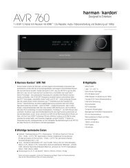
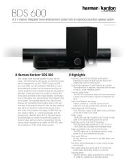
0 Power On Button<br />
1 Not active<br />
2 IR Transmitter Window<br />
3 Power Off Button<br />
4 Mute<br />
5 Input Selectors<br />
6 6-Channel Direct Input<br />
7 Volume Up/Down<br />
8 HD Mode Selector<br />
9 Speaker Select/Setup<br />
A OK Button<br />
B Delay/Status Button<br />
C Memory/Angle Button<br />
D Clear Button<br />
E Preset Up/Down<br />
F RDS Select/Info Button<br />
G Playlist<br />
H A-B<br />
I DTS Neo:6 Mode Selector<br />
J Stereo Mode Selector<br />
K Logic 7 Selector<br />
L Dim Button<br />
M Transport Buttons<br />
N Skip Up/Down Buttons (DWN)/(UP)<br />
O Night Mode<br />
P DTS Digital Mode Selector<br />
Q Dolby Mode Selector<br />
R Repeat<br />
S Random<br />
T Tone Mode/Progressive Scan/Interlaced<br />
Button<br />
U Tuning Up/Down<br />
V Direct Button<br />
W Tuner Mode/Zoom<br />
X Numeric Keys<br />
Y Digital Select/Audio Mode<br />
Z Navigation Buttons<br />
a Channel Select /Disc Menu Button<br />
b V.OFF/Test Button<br />
c Surround Mode Selector/Program Down/<br />
Subtitle Button<br />
d Sleep/Program Up/Audio Select Button<br />
e Title<br />
f AM/FM Tuner Select<br />
g <strong>AVR</strong> Selector
Remote Control Functions, common for <strong>AVR</strong> <strong>142</strong> and a HK DVD Player<br />
IMPORTANT NOTE: The combined <strong>AVR</strong> and DVD<br />
remote has some buttons that perform different<br />
functions. If you press the <strong>AVR</strong> Button g, one set<br />
of functions is active, identical to the functions for<br />
buttons CD, Tape, Video 1/2/3. If you press the DVD/<br />
HDMI1 Button 5, some of the buttons change<br />
their function as indicated above the button itself,<br />
and explained below. Refer to the function table for<br />
an overview of functions in both modes. NoTE that<br />
pressing the HDMI1 and DVD buttons 5 activate<br />
the alternative commands as seen in the function<br />
list on page 7. The DVD functions work with harman/<br />
kardon DVD players only.<br />
0 Power On Button: Press this button to turn on<br />
the power to the <strong>AVR</strong> or the DVD selected by pressing<br />
either the <strong>AVR</strong> or the DVD/HDMI1 Button g or<br />
5.<br />
1 This indicator is not active.<br />
2 IR Transmitter Window: Point this window<br />
towards the <strong>AVR</strong> when pressing buttons on the remote<br />
to make certain that infrared commands are properly<br />
received.<br />
3 Power Off Button: Press this button to place<br />
the <strong>AVR</strong> or a selected device unit in the standby mode.<br />
If held for more than 3 seconds, both the <strong>AVR</strong> and the<br />
DVD switch to standby.<br />
4 Mute: Press this button to momentarily silence<br />
the <strong>AVR</strong> or TV set being controlled, depending on<br />
which device has been selected.<br />
5 Input Selectors: Pressing one of these buttons<br />
will perform three actions at the same time. first, if<br />
the <strong>AVR</strong> is not turned on, this will power up the unit.<br />
Next, it will select the source shown on the button as<br />
the input to the <strong>AVR</strong>. finally, the DVD/HDMI1 button<br />
will switch the double-function remote buttons to<br />
their DVD functions. After pressing the DVD/HDMI1<br />
button, you must press the <strong>AVR</strong> Selector button<br />
g again to operate all the <strong>AVR</strong>’s functions with the<br />
remote. Note that pressing the DVD button switches<br />
on boTH the <strong>AVR</strong> and the DVD, whereas pressing the<br />
<strong>AVR</strong> button just switches on the <strong>AVR</strong>.<br />
6 6-Channel Direct Input: Press this button to<br />
select the component connected to the 6-Channel<br />
Direct Input N as the audio. Note that when you<br />
wish to use the six Channel Direct Input in conjunction<br />
with a video source, you must first select the video<br />
source by pressing one of the Input Selectors 5.<br />
Then press this button to choose the 6-Channel<br />
Direct Input N as the audio source.<br />
7 Volume Up/Down: Press these buttons to raise<br />
or lower the system volume.<br />
8 HD Mode Selector (DVD): This function is<br />
active with harman/kardon DVD players only.<br />
9 Speaker Select/Setup: Press this button<br />
to begin the process of configuring the <strong>AVR</strong>’s bass<br />
Management system for use with the type of speakers<br />
used in your system. once the button has been<br />
pressed, use the KL buttons Z to select the<br />
channel you wish to set up. Press the OK button A<br />
and then select the speaker type (see page 12 for more<br />
information.)<br />
for DVD: Press this button to use the DVD’s on-screen<br />
menu system to adjust the player’s configuration<br />
settings. Note that the Info Button 6 must be<br />
pressed to access the DVD’s Information menu to<br />
obtain detailed disc information, and to configure the<br />
playback mode of the disc.<br />
A OK Button: This button is used to enter settings<br />
into the <strong>AVR</strong>’s memory. It is also used in the setup<br />
procedures for delay time, speaker configuration and<br />
channel output level adjustment.<br />
B Delay/Status Button: Press this button to<br />
begin the process for setting the delay times used<br />
by the <strong>AVR</strong> when processing surround sound. After<br />
pressing this button, the delay times are entered by<br />
pressing the OK button A and then using the KL<br />
buttons Z to change the setting. Press the set<br />
button again to complete the process (see page 14 for<br />
more information).<br />
for DVD: Press while a disc is playing to view banner<br />
display. Use the ARRoW buttons to move through<br />
the different features in the banner Display. When<br />
a symbol is highlighted, press oK on the remote to<br />
select it.<br />
C Memory/Angle Button: Press this button to<br />
enter a radio station into the <strong>AVR</strong>’s preset memory.<br />
Two underline indicators will flash at the right side<br />
of the Main Information Display F, you then<br />
have five seconds to enter a preset memory location<br />
using the Numeric Keys X. (see page 20 for more<br />
information.)<br />
for DVD: Press to access various camera angles on a<br />
DVD (If the DVD contains multiple camera angles) or<br />
to rotate JPEG images.<br />
D Clear Button: Press this button to clear incorrect<br />
entries when using the remote to directly enter a radio<br />
station’s frequency.<br />
E Preset Up/Down: When the tuner is in use,<br />
press these buttons to scroll through the stations<br />
programmed into the <strong>AVR</strong>’s memory. When CD or DVD<br />
is selected using the Input Selector button 5,<br />
these buttons may function as slow fwd/Rev (DVD) or<br />
”+10” (CD).<br />
F RDS Select/Info (DVD) Button: Press this<br />
button to display the various messages that are part of<br />
the RDs data system of the <strong>AVR</strong>’s tuner. (see page 20<br />
for more information on RDs).<br />
for DVD: Press for detailed informations on the disc<br />
playing (Video/Audio bit rate, Movie aspect ratio and<br />
others), and for current player settings made. Note<br />
that the unit doesn’t react on any transport button<br />
as long as the info menu is displayed. Press again to<br />
remove information from screen.<br />
G Playlist (DVD): Press this button to change the<br />
playback order of the disc.<br />
H A-B (DVD): Press to select section A-b and to<br />
play repeatedly.<br />
I DTS Neo:6 Mode Selector: Pressing this<br />
selector button cycles the <strong>AVR</strong> through the various DTs<br />
Neo:6 modes, which extract a five-channel surround<br />
field from two-channel program material (from PCM<br />
source or analog input signal). The first press selects<br />
the last DTs Neo:6 surround mode that was in use, and<br />
each subsequent press selects the next mode in the<br />
following order:<br />
REMoTE CoNTRol fUNCTIoNs<br />
5<br />
ENGLISH
Remote Control Functions, common for <strong>AVR</strong> <strong>142</strong> and a HK DVD Player<br />
J Stereo Mode Selector: Press this button to<br />
select a stereo playback mode. When the button<br />
is pressed so that DSp SURR OFF appears in<br />
the Main Information Display F, the <strong>AVR</strong> will<br />
operate in a bypass mode with true fully analog,<br />
two-channel left/right stereo mode with no surround<br />
processing or bass management as opposed to other<br />
modes where digital processing is used. When the<br />
button is pressed so that SURROUND OFF appears<br />
in the Main Information Display F, you may<br />
enjoy a two-channel presentation of the sound along<br />
with the benefits of bass management. When the<br />
button is pressed so that 5 CH STEREO appears,<br />
the stereo signal is routed to all five speakers, if<br />
installed.(see page 13 for more information on stereo<br />
playback modes).<br />
K Logic 7 Selector: Press this button to select one<br />
of the available logic 7 surround modes. (see page 16<br />
for the available logic 7 options).<br />
L Dim Button: Press this button to activate the<br />
Dimmer function, which reduces the brightness of<br />
the front panel display, or turn it off entirely. The first<br />
press of the button shows the default state, which<br />
is full brightness by indicating VFD FUll in the<br />
Main Information Display F. Press the button<br />
again within five seconds to reduce the brightness by<br />
50%, as indicated by VFD HalF. Press the button<br />
again within five seconds and the main display will go<br />
completely dark. Note that this setting is temporary;<br />
the display will always return to full brightness when<br />
the <strong>AVR</strong> is turned on. In addition,both the Power<br />
Indicator 2 and the blue accent lighting inside the<br />
volume control will always remain at full brightness<br />
regardless of the setting. This is to remind you that the<br />
<strong>AVR</strong> is still turned on.<br />
M Transport Buttons: These buttons operate the<br />
DVD player.<br />
N Skip Up/Down Buttons (DVD):<br />
(DWN): Press to go to beginning of current track. Press<br />
again quickly to go to beginning of previous track.<br />
After pressing the PAUSE button, each press of this<br />
button will move the image in reverse frame by frame.<br />
(UP): Press to go to beginning of next track. After<br />
pressing the PAUSE button, each press of this button<br />
will move the image forwards frame by frame.<br />
O Night Mode: Press this button to activate the<br />
Night mode. This mode is available only with Dolby<br />
Digital encoded digital sources, and it preserves dialog<br />
(center channel) intelligibilty at low volume levels<br />
(see page 14 for more information).<br />
6 REMoTE CoNTRol fUNCTIoNs<br />
P DTS Digital Mode Selector: When a DTs<br />
source is in use the <strong>AVR</strong> will select the appropriate<br />
mode automatically and no other mode will be<br />
available. Pressing this button will display the mode<br />
currently selected by the <strong>AVR</strong>´s decoder, depending on<br />
the surround material played and the speaker setting.<br />
Q Dolby Mode Selector: This button is used to<br />
select one of the available Dolby surround processing<br />
modes. Each press of this button will select one of<br />
the Dolby Pro logic II modes, Dolby 3 stereo or Dolby<br />
Digital. Note that the Dolby Digital mode is only<br />
available with a digital input selected and the other<br />
modes only as long as a Dolby Digital source is not<br />
playing.<br />
R Repeat (DVD): Each press of this button<br />
changes the playback mode to repeat a chapter or<br />
track or the entire disc. A repeat icon will appear in the<br />
upper right corner of the screen indicating the current<br />
repeat mode. If the Player Information screen is active,<br />
the changes will be displayed on screen.<br />
S Random (DVD): Press for RANDoM playback in<br />
random order.<br />
T Tone Mode/Progressive Scan/Interlaced<br />
Button: Pressing this button enables or disables the<br />
bass and Treble tone controls. When the button is<br />
pressed so that the words TONE IN appear in the<br />
Main Information Display F, the settings of<br />
the Bass and Treble controls will affect the output<br />
signals. When the button is pressed so that the words<br />
TONE OUT appear in the Main Information<br />
Display F, the output signal will be “flat,” without<br />
any bass or treble alteration.<br />
for DVD: Press this button to change the resolution<br />
of the Component Video output between standard<br />
definition and progressive definition (PAl interlaced<br />
and PAl progressive; NTsC interlaced and NTsC<br />
progressive).<br />
The new setting will become effective after quitting<br />
the setup menu.<br />
U Tuning Up/Down: When the tuner is in use,<br />
these buttons will tune up or down through the<br />
selected frequency band. If the Tuner Mode button<br />
W has been pressed or the Band button 8 on the<br />
front panel was held pressed so that aUTO appears<br />
in the Main Information Display F, pressing<br />
either of the buttons will cause the tuner to seek the<br />
next station with acceptable signal strength for quality<br />
reception. When the maNUal appears in the Main<br />
Information Display F, pressing these buttons<br />
will tune stations in single-step increments. (see page<br />
20 for more information).<br />
V Direct Button: Press this button when the<br />
tuner is in use to start the sequence for direct entry<br />
of a station’s frequency. After pressing the button<br />
simply press the proper Numeric Keys X to select<br />
a station (see page 20 for more information on the<br />
tuner).<br />
W Tuner Mode/Zoom: Press this button when<br />
the tuner is in use to select between automatic tuning<br />
and manual tuning. When the button is pressed<br />
so maNUal appears in the Main Information<br />
Display F, pressing the Tuning buttons U7<br />
will move the frequency up or down in single-step<br />
increments. When the fM band is in use and aUTO<br />
appears in the Main Information Display F,<br />
pressing this button will change to monaural reception<br />
making even week stations audible. (see page 20 for<br />
more information.)<br />
When a DVD or VCD is playing, press this button to<br />
zoom the picture so that it is enlarged. There are 4<br />
steps to the zoom function, each progressively larger.<br />
Press through each of the zoom stages to return to a<br />
normal picture.<br />
X Numeric Keys: These buttons serve as a tenbutton<br />
numeric keypad to enter tuner preset positions.<br />
for DVD play you may enter track numbers directly,<br />
followed by oK to go to the track.<br />
Y Digital Select/Audio Mode: Press this button<br />
to assign one of the digital inputs 4G9L to a<br />
source. (see page 10 for more information on using<br />
digital inputs.) Audio Mode: When operating the<br />
DVD, press this button to switch between Audio<br />
Modes.<br />
Z Navigation Buttons: These are multi-purpose<br />
buttons. They will be used most frequently to select<br />
a surround mode. These buttons are also used to<br />
increase or decrease output levels when configuring<br />
the unit, to select speaker configuration or to select the<br />
digital inputs.<br />
a Channel Select /Disc Menu Button: This<br />
button is used to start the process of setting the <strong>AVR</strong>’s<br />
output levels with an external source. once this button<br />
is pressed, use the KL buttons Z to select the<br />
channel being adjusted, then press the OK button<br />
A, followed by the KL buttons again, to change<br />
the level setting. (see page 19 for more information.)<br />
DVD Disc Menu: Displays the actual DVD Disc Menu<br />
on the TV screen in play mode. When playing discs<br />
with JPEG images, pressing this button will access the<br />
thumbnails.<br />
b V.OFF/Test Button: Press to turn off video<br />
output of a DVD-player for improved performance<br />
from audio-only discs. Press again to restore video<br />
output.<br />
Tone: Press this button to begin the sequence used<br />
to calibrate the <strong>AVR</strong>’s output levels. (see page 14 for<br />
more information on calibrating the <strong>AVR</strong>).
Remote Control Functions, common for <strong>AVR</strong> <strong>142</strong> and a HK DVD Player<br />
c Surround Mode Selector/Program Down/<br />
Subtitle Button: Press this button to begin the<br />
process of changing the surround mode. After the<br />
button has been pressed, use the KL buttons Z<br />
to select the desired surround mode. (see page 16 for<br />
more information).<br />
When a DVD is playing, press to select a subtitle<br />
language or to turn subtitles off.<br />
Note: Due to the variations in how DVD discs are<br />
authored, the subtitle languages selected with the<br />
subtitle button may not accurately reflect the actual<br />
languages available on the disc. It is recommended<br />
that subtitles be selected using the disc’s menu.<br />
d Sleep/Program Up/Audio Select Button:<br />
Press this button to place the unit in the sleep mode.<br />
After the time shown in the display, the <strong>AVR</strong> will<br />
automatically go into the standby mode. Each press<br />
of the button changes the time until turn-off in the<br />
following order:<br />
Hold the button pressed for two seconds to turn off the<br />
sleep mode setting.<br />
DVD: Press to access various audio languages on a DVD<br />
(If the DVD contains multiple audio streams).<br />
e Title: When a disc is playing, press to make the<br />
DVD-player go back to the first section of the disc. If<br />
you are playing a DVD-Audio disc that contains other<br />
formats the DVD is capable of playing, such as linear<br />
PCM or Dolby Digital 5.1, pressing this button may<br />
enable you to switch playback from one audio format<br />
to another.<br />
f AM/FM Tuner Select: Press this button to select<br />
the <strong>AVR</strong>’s tuner as the listening choice. Pressing this<br />
button when the tuner is in use will select between<br />
the AM and fM bands.<br />
g <strong>AVR</strong> Selector: Pressing this button will switch<br />
the remote so that it will operate the <strong>AVR</strong>’s functions.<br />
If the <strong>AVR</strong> is in the standby mode, it will also turn the<br />
<strong>AVR</strong> on.<br />
Function List<br />
HK <strong>AVR</strong> Remote Command<br />
HK DVD Remote Command<br />
Button Name<br />
<strong>AVR</strong>/TAPE/CD/AUX/VID1/VID2/VID3/HDMI2/HDMI3 DVD/HDMI1<br />
Power ON Power on Power on<br />
Power OFF Power off (press and release) Power off (press and release)<br />
Power off (press and hold) Power off (press and hold)<br />
Mute Mute Mute(<strong>AVR</strong>)<br />
<strong>AVR</strong> <strong>AVR</strong> Power on <strong>AVR</strong>(<strong>AVR</strong>)<br />
DVD DVD DVD(<strong>AVR</strong>)<br />
VID1 VID 1 VID 1(<strong>AVR</strong>)<br />
HDMI1 HDMI 1 HDMI 1(<strong>AVR</strong>)<br />
AM/FM AM/fM AM/fM(<strong>AVR</strong>)<br />
CD CD CD(<strong>AVR</strong>)<br />
VID2 VID 2 VID 2(<strong>AVR</strong>)<br />
HDMI2 HDMI 2 HDMI 2(<strong>AVR</strong>)<br />
AUX AUX AUX(<strong>AVR</strong>)<br />
TAPE TAPE TAPE(<strong>AVR</strong>)<br />
VID3 VID 3 VID 3(<strong>AVR</strong>)<br />
HDMI3 HDMI 3 HDMI 3(<strong>AVR</strong>)<br />
SLEEP / AUDIO sleep Audio<br />
TITLE Title<br />
6CH 6CH 6CH(<strong>AVR</strong>)<br />
VOL Up Vol Up Vol Up(<strong>AVR</strong>)<br />
SURR. / SUBT. surround Mode subtitle<br />
TEST / V.OFF Test Tone Video off<br />
HD-M HD Mode<br />
VOL Down Vol Down Vol Down(<strong>AVR</strong>)<br />
CH. / DISC MENU Channel select Disc Menu<br />
SPKR / SETUP speaker select setup<br />
Level+/Up level+/Up Up<br />
Left M left left<br />
OK sET Enter<br />
Right N Right Right<br />
Level-/Down level-/Down Down<br />
DIGITAL / AUDIO MODE Digital select Audio Mode<br />
DELAY / STATUS Delay status<br />
1 1 1<br />
2 2 2<br />
3 3 3<br />
4 4 4<br />
5 5 5<br />
6 6 6<br />
7 7 7<br />
8 8 8<br />
TUN-M / ZOOM Tuner Mode Zoom<br />
9 9 9<br />
0 0 0<br />
MEM / ANGLE Memory Angle<br />
TUNING Up Tuning Up<br />
DIRECT Direct Tuning<br />
CLEAR Clear Clear<br />
PRESET Up Preset Up slow Up<br />
TUNING Down Tuning Down<br />
TONE / P/I Tone Mode P/I<br />
RDS / INFO RDs Info<br />
PRESET Down Preset Down slow Down<br />
RANDOM Random Play<br />
REPEAT Repeat Play<br />
A-B A-b Repeat Play<br />
PLAYLIST Playlist<br />
DOLBY SUR Dolby surround Dolby surround(<strong>AVR</strong>)<br />
DTS SUR DTs surround DTs surround(<strong>AVR</strong>)<br />
DTS NEO:6 DTs NEo:6 DTs NEo:6(<strong>AVR</strong>)<br />
NIGHT Night Mode Night(<strong>AVR</strong>)<br />
LOGIC 7 logic7 logic7(<strong>AVR</strong>)<br />
STEREO stereo stereo(<strong>AVR</strong>)<br />
SKIP DOWN skip Down(DVD) skip Down<br />
SKIP UP skip Up(DVD) skip Up<br />
DIM Dimmer Dimmer<br />
Rew(G) Rew(DVD) Rew<br />
Play(B) Play(DVD) Play<br />
FF(H) ff(DVD) ff<br />
Open/Close open/Close(DVD) open/Close<br />
Stop stop(DVD) stop<br />
Pause Pause(DVD) Pause<br />
REMoTE CoNTRol fUNCTIoNs<br />
7<br />
ENGLISH
<strong>AVR</strong> Audio/Video Receiver<br />
Front Panel Controls<br />
8<br />
<strong>AVR</strong> <strong>142</strong><br />
fRoNT PANEl CoNTRols<br />
1 2 � 6 C 7 8 9 A<br />
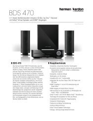
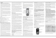
0 Main Power Switch: Press this button to apply<br />
power to the <strong>AVR</strong>. When the switch is pressed in, the<br />
unit is placed in a standby mode, as indicated by the<br />
orange lED 2. This button MUsT be pressed in to<br />
operate the unit. To turn the unit off completely and<br />
prevent the use of the remote control, this switch<br />
should be pressed until it pops out from the front<br />
panel so that the word “off” may be read at the top of<br />
the switch.<br />
NOTE: This switch is normally left in the “oN” position.<br />
1 System Power Control: When the Main Power<br />
Switch 0 is “oN,” press this button to turn on the<br />
<strong>AVR</strong>; press it again to turn the unit off (to standby).<br />
Note that the Power Indicator 2 will turn blue<br />
when the unit is on.<br />
2 Power Indicator: This lED will be illuminated in<br />
orange when the unit is in the standby mode to signal<br />
that the unit is ready to be turned on. When the unit is<br />
in operation, the indicator will turn blue.<br />
3 Headphone Jack: This jack may be used to listen<br />
to the <strong>AVR</strong>’s output through a pair of headphones.<br />
be certain that the headphones have a standard 6.3<br />
mm stereo phone plug. Note that the speakers will<br />
automatically be turned off when the headphones are<br />
connected.<br />
4 Digital Optical 3 Input: Connect the optical<br />
digital audio output of an audio or video product to<br />
this jack.<br />
5 Aux input stereo minijack: Connect this<br />
minijack to any audio source, typically MP3 players or<br />
portable CD players. An analog headphone output jack<br />
or line level out jack may be used.<br />
6 Surround Mode Group Selector: Press this<br />
button to select the top-level group of surround<br />
modes. Each press of the button will select a major<br />
mode grouping in the following order:<br />
Dolby Modes > DTs Digital Modes > DsP Modes ><br />
stereo Modes > logic 7 Modes<br />
F E D<br />
once the button is pressed so that the name of the<br />
desired surround mode group appears in the Lower<br />
Display Line F, press the Surround Mode<br />
Selector C to cycle through the individual modes<br />
available. for example, press this button to select<br />
Dolby modes, and then press the Surround Mode<br />
Selector C to choose from the various mode<br />
options.<br />
7 Tuning Selector: Press the left side of the<br />
button to tune lower frequency stations and the right<br />
side of the button to tune higher frequency stations.<br />
When a station with a strong signal is reached,<br />
maNUal TUNED or aUTO TUNED will appear<br />
in the Main Information Display F (see page 20<br />
for more information on tuning stations).<br />
8 Tuner Band Selector: Pressing this button will<br />
automatically switch the <strong>AVR</strong> to the Tuner mode.<br />
Pressing it again will switch between the AM and fM<br />
frequency bands, holding it pressed for some seconds<br />
will switch between stereo and mono receiving and<br />
between automatic and manual tuning mode (see<br />
page 20 for more information on the tuner).<br />
9 Preset Stations Selector: Press this button to<br />
scroll up or down through the list of stations that have<br />
been entered into the preset memory. (see page 20 for<br />
more information on tuner programming.)<br />
A Input Source Selector: Press this button to<br />
change the input by scrolling through the list of input<br />
sources.<br />
B RDS Select Button: Press this button to display<br />
the various messages that are part of the RDs data<br />
system of the <strong>AVR</strong>’s tuner. (see page 20 for more<br />
information on RDs).<br />
C Surround Mode Selector: Press this button<br />
to select from among the available surround mode<br />
options for the mode group selected. The specific<br />
modes will vary based on the number of speakers<br />
available, the mode group and if the input source is<br />
digital or analog. for example, press the Surround<br />
Mode Group Selector 6 to select a mode grouping<br />
3<br />
B 4 G 5 H<br />
such as Dolby or logic 7, and then press this button to<br />
see the mode choices available. for more information<br />
on mode selection, see page 13.<br />
D Volume Control: Turn this knob clockwise to<br />
increase the volume, counterclockwise to decrease the<br />
volume. If the <strong>AVR</strong> is muted, adjusting volume control<br />
will automatically release the unit from the silenced<br />
condition.<br />
E Remote Sensor Window: The sensor behind<br />
this window receives infrared signals from the remote<br />
control. Aim the remote at this area and do not<br />
block or cover it unless an external remote sensor is<br />
installed.<br />
F Main Information Display: This display delivers<br />
messages and status indications to help you operate<br />
the receiver.<br />
G Digital Coax 3 Input: This jack is normally used<br />
for connection to the output of portable digital audio<br />
devices, video game consoles or other products that<br />
have a coax digital jack.<br />
H Video 3 Input Jacks: These audio/video jacks<br />
may be used for temporary connection to video games<br />
or portable audio/video products such as camcorders<br />
and portable audio players.
Rear Panel Connections<br />
�<br />
�<br />
�<br />
�<br />
�<br />
�<br />
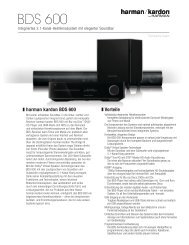
0 Tape Inputs: Connect these jacks to the PLAY/<br />
OUT jacks of an audio recorder.<br />
1 Tape Outputs: Connect these jacks to the<br />
RECORD/INPUT jacks of an audio recorder.<br />
2 Video 1 Audio Inputs: Connect these jacks to<br />
the PLAY/OUT audio jacks on a TV or other video<br />
source.<br />
3 AM Antenna: Connect the AM loop antenna<br />
supplied with the receiver to these terminals. If an<br />
external AM antenna is used, make connections to<br />
the AM and GND terminals in accordance with the<br />
instructions supplied with the antenna.<br />
4 Video 1 Audio Outputs: Connect these jacks to<br />
the RECORD/INPUT audio jacks on a VCR or any other<br />
Audio recorder.<br />
5 DVD Audio Inputs: Connect these jacks to the<br />
analog audio jacks on a DVD or other video source.<br />
6 FM Antenna: Connect the supplied indoor or an<br />
optional external fM antenna to this terminal.<br />
7 CD Inputs: Connect these jacks to the analog<br />
output of a compact disc player or CD changer.<br />
8 Video 1 Component Video Inputs: Connect<br />
the y/Pr/Pb component video outputs of an HDTV settop<br />
convertor, satellite receiver, or other video source<br />
device with component video outputs to these jacks.<br />
9 Coaxial Digital Inputs: Connect the coax digital<br />
output from a DVD player, HDTV receiver, lD player, MD<br />
player or CD player to these jacks. The signal may be<br />
either a Dolby Digital signal, DTs signal or a standard<br />
PCM digital source.<br />
Do not connect the Rf digital output of an lD player to<br />
these jacks.<br />
A Subwoofer Output: Connect this jack to the<br />
line-level input of a powered subwoofer. If an external<br />
subwoofer amplifier is used, connect this jack to the<br />
subwoofer amplifier input.<br />
�<br />
� � � � � � � �<br />
�<br />
�<br />
� � � �<br />
� �<br />
� � � �<br />
�<br />
�<br />
B Video Monitor Output: Connect these jacks to<br />
the composite input of a TV monitor or video projector<br />
to view the output of any video source selected by the<br />
receiver’s video switcher.<br />
C HDMI Inputs: Connect the HDMI output of video<br />
sources such as a DVD player, set-top box or HDTV<br />
tuner to either of these three jacks.<br />
� HDMI Output: Connect this jack to the HDMI<br />
input on a compatible HDMI-equipped video display.<br />
E Monitor Component Video Outputs: Connect<br />
these outputs to the component video inputs of a<br />
video projector or monitor. When a source connected<br />
to one of the two Component Video Inputs 8F<br />
is selected the signal will be sent to these jacks.<br />
F Video 2 Component Video Inputs: Connect<br />
the y/Pr/Pb component video outputs of a DVD player<br />
to these jacks.<br />
Note: All component inputs/outputs can be used for<br />
RGb signals too, in the same way as described for the<br />
y/Pr/Pb signals, then connected to the jacks with the<br />
corresponding color.<br />
RGb connection is not possible if the source outputs a<br />
separate sync signal (see page 11).<br />
G AC Power Cord: Connect the AC plug to an<br />
unswitched AC wall output.<br />
H DVD Video Inputs: Connect these jacks to the<br />
composite output jacks on a DVD player or other video<br />
source.<br />
I Video 1 Video Outputs: Connect these jacks to<br />
the RECORD/INPUT composite jack on a VCR.<br />
J Video 2 Audio Inputs: Connect these jacks to the<br />
PLAY/OUT audio jacks on a VCR or other video source.<br />
K Video 2 Video Inputs: Connect these jacks to the<br />
PLAY/OUT composite jacks on a second VCR or other<br />
video source.<br />
�<br />
�<br />
<strong>AVR</strong> <strong>142</strong>/230<br />
L Optical Digital Inputs: Connect the optical<br />
digital output from a DVD player, HDTV receiver, lD<br />
player, MD player or CD player to these jacks. The<br />
signal may be either a Dolby Digital signal, a DTs<br />
signal or a standard PCM digital source.<br />
M Video 1 Video Inputs: Connect these jacks to<br />
the PLAY/OUT composite jacks on a TV or other video<br />
source.<br />
N 6-Channel Direct Inputs: These jacks are used<br />
for connection to source devices such as DVD-Audio or<br />
sACD players with discrete analog outputs.<br />
� Digital Audio Output: Connect this jack to the<br />
matching digital input connector on a digital recorder.<br />
��� Front/Center Speaker Outputs: Connect<br />
these outputs to the matching + or – terminals on<br />
your front/center speakers. When making speaker<br />
connections, always make certain to maintain correct<br />
polarity by connecting the red (+) terminals on the<br />
<strong>AVR</strong> to the red (+) terminals on the speaker and<br />
the black (–) terminals on the <strong>AVR</strong> to the black (–)<br />
terminals on the speakers. (see page 12 for more<br />
information on speaker polarity.)<br />
�� Surround Speaker Outputs: Connect these<br />
outputs to the matching + or – terminals on your left<br />
and right surround speakers. When making speaker<br />
connections always make certain to maintain correct<br />
polarity by connecting the red (+) terminals on the<br />
<strong>AVR</strong> to the red (+) terminals on the speakers and<br />
the black (–) terminals on the <strong>AVR</strong> to the black (–)<br />
terminals on the speakers. see page 12 for more<br />
information on speaker polarity.<br />
REAR PANEl CoNNECTIoNs<br />
9<br />
ENGLISH
Installation and Connections<br />
After unpacking the unit, and placing it on a solid<br />
surface capable of supporting its weight, you will<br />
need to make the connections to your audio and video<br />
equipment.<br />
Audio Equipment Connections<br />
We recommend that you use high-quality interconnect<br />
cables when making connections to source equipment<br />
and recorders to preserve the integrity of the signals.<br />
When making connections to audio source equipment<br />
or speakers it is always a good practice to unplug<br />
the unit from the AC wall outlet. This prevents any<br />
possibility of accidentally sending audio or transient<br />
signals to the speakers that may damage them.<br />
Important Note: In order to clearly identify all<br />
connectors and simplify nstallation, as per the new<br />
EIA/CEA-863 standard, all connections are colour<br />
coded as follows:<br />
for speakers and Audio In/outputs: White (left,<br />
speakers front) and Red (Right, speakers front).<br />
for speakers: Green (Center), blue (left surround) and<br />
Grey (Right surround).<br />
for Audio output: Purple (subwoofer).<br />
for Composite Video In/outputs: yellow.<br />
for Digital Audio In/outputs: orange.<br />
1. Connect the analog output of a CD player to the CD<br />
inputs 7.<br />
NOTE: When the CD player has both fixed and variable<br />
audio outputs it is best to use the fixed output unless<br />
you find that the input to the receiver is so low that the<br />
sound is noisy, or so high that the signal is distorted.<br />
2. Connect the analog Play/out jacks of a cassette<br />
deck, MD, CD-R or other audio recorder to the<br />
Tape Input jacks 0. Connect the analog Record/<br />
In jacks on the recorder to the Tape Output jacks<br />
1 on the <strong>AVR</strong>.<br />
3. Connect the output of any digital sources to<br />
the appropriate input connections on the <strong>AVR</strong><br />
rear panel. Note that the Optical and Coaxial<br />
digital inputs L94G may be used with<br />
a Dolby Digital or DTs source or the output of a<br />
conventional CD, MD or lD player’s PCM (s/P-DIf)<br />
output.<br />
4. Assemble the AM loop Antenna supplied with the<br />
unit as shown below. Connect it to the AM and<br />
GND screw terminals 3.<br />
10 INsTAllATIoN AND CoNNECTIoNs<br />
5. Connect the supplied fM antenna to the FM<br />
(75 ohm) connection 6. The fM antenna may<br />
be an external roof antenna, an inside powered<br />
or wire lead antenna or a connection from a cable<br />
system. Note that if the antenna or connection<br />
uses 300-ohm twin-lead cable, you must use<br />
a 300-ohm-to-75-ohm adapter to make the<br />
connection.<br />
6. Connect the front, center and surround speaker<br />
outputs to the respective speakers.<br />
To assure that all the audio signals are carried to<br />
your speakers without loss of clarity or resolution,<br />
we suggest that you use high-quality speaker cable.<br />
Many brands of cable are available and the choice of<br />
cable may be influenced by the distance between your<br />
speakers and the receiver, the type of speakers you use,<br />
personal preferences and other factors. your dealer or<br />
installer is a valuable resource to consult in selecting<br />
the proper cable.<br />
Regardless of the brand of cable selected, we<br />
recommend that you use a cable constructed of fine,<br />
multistrand copper with an area greater than 2 mm2 .<br />
Cable with an area of 1.5 mm2 may be used for short<br />
runs of less than 4 m. We do not recommend that you<br />
use cables with an area less than 1mm2 due to the<br />
power loss and degradation in per for mance that will<br />
occur.<br />
When connecting wires to the speakers, be certain<br />
to observe proper polarity. Remember to connect the<br />
“negative” or “black” wire to the same terminal on both<br />
the receiver and the speaker. similarly, the “positive” or<br />
“red” wire should be connected to like terminals on the<br />
<strong>AVR</strong> and speaker.<br />
NOTE: While most speaker manufacturers adhere<br />
to an industry convention of using black terminals<br />
for negative and red ones for positive, some<br />
manufacturers may vary from this configuration.<br />
To assure proper phase and optimal performance,<br />
consult the identification plate on your speaker or<br />
the speaker’s manual to verify polarity. If you do not<br />
know the polarity of your speaker, ask your dealer<br />
for advice before proceeding, or consult the speaker’s<br />
manufacturer.<br />
We also recommend that the length of cable used to<br />
connect speaker pairs be identical. for example, use<br />
the same length piece of cable to connect the frontleft<br />
and front-right or surround-left and surround-right<br />
speakers, even if the speakers are a different distance<br />
from the <strong>AVR</strong>.<br />
7. Connections to a subwoofer are normally made via<br />
a line level audio connection from the Subwoofer<br />
Output A to the line-level input of a subwoofer<br />
with a built-in amplifier. When a passive<br />
subwoofer is used, the connection first goes to a<br />
power amplifier, which will be connected to one or<br />
more subwoofer speakers.<br />
If you are using a powered subwoofer that does<br />
not have line-level input connections, follow<br />
the instructions furnished with the speaker for<br />
connection information.<br />
Note: speaker sets with two front satellites and<br />
a passive subwoofer must be connected to the<br />
front speaker outputs only rather than to the<br />
Subwoofer Output A.<br />
8. If an external multi-channel audio source with<br />
5.1 outputs such as an external digital processor/<br />
decoder, DVD-Audio or sACD player is used,<br />
connect the outputs of that device to the<br />
6-Channel Direct Inputs N.<br />
Video Equipment Connections<br />
Video equipment is connected in the same manner<br />
as audio components. Again, the use of high-quality<br />
interconnect cables is recommended to preserve signal<br />
quality.<br />
1. Connect a VCR’s audio and video Play/out jacks to<br />
the Video 2 In jacks JK on the rear panel. The<br />
Audio and Video Record/In jacks on the VCR should<br />
be connected to the Video 1 Out jacks 4I<br />
on the <strong>AVR</strong>.<br />
2. Although any video device may be connected to<br />
these jacks, we recommend connecting your TV to<br />
the Video 1 Audio/Video Input Jacks 2M so<br />
that you may take advantage of the fact that the<br />
remote control is preprogrammed with TV product<br />
codes for the Video 1 device.<br />
for the same reason, we recommend connecting<br />
your video recorder, cable TV converter or satellite<br />
receiver to the Video 2 Audio/Video Input<br />
Jacks JK.<br />
3. Connect the analog audio and video outputs of a<br />
DVD to the DVD jacks 5C. This is valid only<br />
if your DVD player does not have a HDMI output.<br />
If a HDMI output is available on the DVD player,<br />
connect it to the HDMI Inputs C. Please note<br />
that these Inputs are Video only. Audio must be<br />
connected separately.<br />
4. Connect the digital audio outputs of a CD, MD or<br />
DVD player, satellite receiver, cable box or HDTV<br />
converter to the appropriate Optical or Coaxial<br />
Digital Inputs 9L4G.<br />
Remember that the DVD source defaults to the<br />
Coaxial 1 Digital Input 9. All other sources<br />
default to their analog inputs, although any source<br />
may be assigned to any digital audio input on the<br />
receiver.
Installation and Connections<br />
5. Connect the Composite Monitor Output B<br />
jacks on the receiver to the composite input of your<br />
television monitor or video projector.<br />
6. If your DVD player and monitor both have<br />
component video connections, connect the<br />
component outputs of the DVD player to the<br />
Video 1 Component Video Inputs 8. Note<br />
that even when component video connections are<br />
used the audio connections must still be made to<br />
either the analog DVD Audio Inputs 5 or any<br />
of the Coaxial or Optical Digital Input jacks<br />
9L.<br />
7. If another component video device is available,<br />
connect it to the Video 2 Component Video<br />
Input jacks F. The audio connections for this<br />
device should be made to either the Video 2<br />
Input jacks J or any of the Coaxial or Optical<br />
Digital Input jacks 9L.<br />
8. If the component video inputs are used, connect<br />
the Component Video Output E to the<br />
component video inputs of your TV, projector or<br />
display device.<br />
9. If you have a camcorder, video game or other audio/<br />
video device that is connected to the <strong>AVR</strong> on a<br />
temporary, rather than permanent basis, connect<br />
the audio, video and digital audio outputs of that<br />
device to the Front Panel Inputs 4GH.<br />
A device connected to the Video 3 jacks H is<br />
selected as the Video 3 input, and connected to<br />
the digital jacks 4G it is selected as "optical<br />
3" or "Coaxial 3" input. (see page 14 for more<br />
information on input configuration.)<br />
10. Connect the <strong>AVR</strong> to your video display using one of<br />
the following connections, even if you will also use<br />
an HDMI connection:<br />
• If your video display has component<br />
video inputs (y/Pr/Pb), connect the<br />
ComponentVideo Output K.<br />
• If your display does not have component video<br />
inputs, connect the Video Monitor Output<br />
B (Composite) on the <strong>AVR</strong> to the matching<br />
input on your display. only one connection is<br />
needed.<br />
Video Connection Notes:<br />
• y/Pr/Pb Component, RGb, or Composite video<br />
signals may only be viewed in their native formats<br />
and will not be converted to the other formats.<br />
• All component inputs/outputs can be used for RGb<br />
signals too, in the same way as described for the<br />
y/Pr/Pb signals, then connected to the jacks with<br />
the corresponding color. but this is only correct<br />
as long as only the three RGb video signals are<br />
output by the video source, with a sync signal in<br />
the "G" signal only, without any sync signal output<br />
separately by the source.<br />
HDMI Connections<br />
HDMI is the abbreviation for High-Definition<br />
Multimedia Interface, which is quickly becoming the<br />
standard connection point between advanced video/<br />
audio source products and displays, particularly<br />
for high-definition video signals. HDMI is a digital<br />
connection, eliminating the need to convert signals<br />
back and forth from digital to analog.<br />
some source or display components in your system<br />
may use DVI (Digital Video Interface) for digital video<br />
connections. DVI carries the same digital video signals<br />
as HDMI but uses a larger connector and does not<br />
transport audio or control signals. In most cases,<br />
you may mix and match DVI and HDMI digital video<br />
connections by using optional connector adapters.<br />
Note, however, that some DVI-equipped video displays<br />
are not compatible with the HDCP copy protection<br />
coding that is increasingly carried with signals<br />
connected via HDMI. If you have an HDMI source and a<br />
DVI-equipped display, you may occasionally be unable<br />
to view a program if the display does not include HDCP.<br />
This is not the fault of the <strong>AVR</strong> or your source; it simply<br />
indicates that the video display is not compatible.<br />
The <strong>AVR</strong> <strong>142</strong> is equipped for HDMI switching, which<br />
means that it is able to select either of the three HDMI<br />
inputs as the source that feeds your system’s video<br />
display. This preserves the digital signal in its original<br />
form by passing it directly through from source to<br />
display. However, this also means that the <strong>AVR</strong> does<br />
not have access to the signal and thus it is not able to<br />
add menus or on-screen messages to HDMI signals, or<br />
to process the audio that may be part of the signal in<br />
an HDMI connection.<br />
Therefore, the following connections are required<br />
when the <strong>AVR</strong> is used with HDMI sources:<br />
• Connect the HDMI output of a source to either of<br />
the HDMI Inputs C.<br />
• Connect the HDMI Output � of the <strong>AVR</strong> to an<br />
HDMI input on your display.<br />
• Connect either an optical or coaxial digital audio<br />
output from the source to the <strong>AVR</strong>. The default<br />
connections are Coaxial 2 9 for a source<br />
connected to HDMI 1 C and Optical 2 L for a<br />
source connected to HDMI 2 �. you may use any<br />
digital or analog audio source in conjunction with<br />
the HDMI inputs, but if it varies from the default<br />
you must make a change to the input’s setting, as<br />
shown on page 18.<br />
• Even when HDMI inputs are used, it is important<br />
to make sure that a component or composite<br />
video connection is made between the <strong>AVR</strong> and<br />
your display. This is needed to view both the<br />
setup menus and onscreen messages, and to<br />
view other (non-HDMI) video sources. The <strong>AVR</strong><br />
does not convert analog video signals to HDMI.<br />
• All component inputs/outputs can be used for RGb<br />
signals too, in the same way as described for the<br />
y/Pr/Pb signals, then connected to the jacks with<br />
the corresponding color. but this is only correct<br />
as long as only the three RGb video signals are<br />
output by the video source, with a sync signal in<br />
the "G" signal only, without any sync signal output<br />
separately by the source.<br />
INsTAllATIoN AND CoNNECTIoNs<br />
11<br />
ENGLISH
System Configuration<br />
once the speakers have been placed in the room<br />
and connected, the remaining steps are to program<br />
the system configuration memories. With the <strong>AVR</strong><br />
two kind of memories are used, those associated<br />
individually with the input selected, e.g. surround<br />
modes, and others working independently from any<br />
input selected like speaker output levels, or delay<br />
times used by the surround sound processor.<br />
First Turn On<br />
you are now ready to power up the <strong>AVR</strong> to begin these<br />
final adjustments.<br />
1. Plug the Power Cable G into an un switched<br />
AC outlet.<br />
2. Press the Main Power Switch 0 in until it<br />
latches and the word “off” on the top of the switch<br />
disappears inside the front panel. Note that the<br />
Power Indicator 2 will turn orange, indicating<br />
that the unit is in the standby mode.<br />
3. Remove the protective plastic film from the frontpanel<br />
lens. If left in place, the film may affect the<br />
performance of your remote control.<br />
4. Install the three supplied AAA batteries in the<br />
remote as shown. be certain to follow the (+) and<br />
(–) polarity indicators that are on the bottom of<br />
the battery compartment.<br />
5. Turn the <strong>AVR</strong> on either by pressing the System<br />
Power Control 1 or the Input Source<br />
Selector A on the front panel, or via the remote<br />
by pressing the <strong>AVR</strong> Selector g or any of the<br />
Input Selectors 5 on the remote. The Power<br />
Indicator 2 will turn blue to confirm that the<br />
unit is on, and the Main Information Display<br />
F will also light up.<br />
NOTE: After pressing one of the Input Selector<br />
buttons 5 to turn the unit on, press the <strong>AVR</strong><br />
Selector g to have the remote control the <strong>AVR</strong><br />
functions.<br />
12 sysTEM CoNfIGURATIoN<br />
Settings to be Made With Each<br />
Input Used<br />
The <strong>AVR</strong> features an advanced memory system that<br />
enables you to establish different settings for the<br />
speaker configuration, digital input, surround mode,<br />
delay times and output levels for each input source.<br />
This flexibility enables you to custom tailor the way<br />
in which you listen to each source and have the <strong>AVR</strong><br />
memorize them. This means, for example, that you<br />
may associate different surround modes and analog<br />
or digital inputs with different sources, or set different<br />
speaker configurations with the resultant changes<br />
to the bass management system or the use of the<br />
Center speaker. once these settings are made, they<br />
will automatically be recalled when ever you select an<br />
input.<br />
The default settings for the <strong>AVR</strong>, as it is shipped from<br />
the factory, have all inputs set for an analog source<br />
(except for the DVD input, which has the Coaxial<br />
Digital Input 1 9 as the default), with logic 7<br />
Music as the surround mode, all speaker positions set<br />
to "small", and a subwoofer connected. before using<br />
the unit, you will probably want to change these<br />
settings for most inputs so that they are properly<br />
configured to reflect the use of digital or analog inputs,<br />
the type of speakers installed and the surround mode<br />
associated with the input.<br />
Input Setup<br />
The first step in configuring the <strong>AVR</strong> is to select an<br />
input. This may be done by pressing the front panel<br />
Input Source Selector A until the desired input’s<br />
name appears in the Main Information Display<br />
F. The input may also be selected by pressing the<br />
appropriate Input selector on the remote control<br />
5g.<br />
The second step is to associate one of the digital<br />
inputs with the selected input source (if this is needed,<br />
otherwise the selected analog input will remain).<br />
Press the Digital Input Select button Y on<br />
the remote. Within five seconds, make your input<br />
selection using the KL buttons Z on the remote<br />
until the desired digital or analog input is shown in<br />
the Main Infor ma tion Display F. Then press<br />
the OK button A to enter the new digital input<br />
assignment.<br />
After the setting has been made with one input, repeat<br />
as described above with all inputs in use. The digital<br />
input associated with the input selected can also be<br />
changed at any time later and the <strong>AVR</strong>’s memory<br />
system will keep the settings until they are changed<br />
again.<br />
Speaker Setup<br />
This setup tells the <strong>AVR</strong> which type of speakers are in<br />
use. This is important as it adjusts the settings that<br />
determine which speakers receive low frequency<br />
(bass) information and whether a Center speaker<br />
should be used or not, separately for each input<br />
used. for each of these settings use the laRGE<br />
setting if the speakers for a particular position are<br />
traditional full-range loudspeakers that are capable of<br />
reproducing sounds below 100Hz. Use the Small<br />
setting for smaller, frequency-limited satellite speakers<br />
that do not reproduce sounds below 100Hz. Note that<br />
when “small” front (left and right) speakers are used,<br />
a subwoofer is required to reproduce low frequency<br />
sounds. If you are in doubt as to which category<br />
describes your speakers, consult the specifications in<br />
the speakers’ owner’s manual, or ask your dealer.<br />
With the <strong>AVR</strong> turned on, follow these steps to<br />
configure the speakers:<br />
1. Press the Speaker button 9 on the remote.<br />
The words FRONT SpEaKER will appear in<br />
the Main Information Display F.<br />
2. Press the OK button A.<br />
3. Press the KL buttons Z on the remote to select<br />
FRONT laRGE or FRONT Small,<br />
matching the type of speakers you have at the leftfront<br />
and right-front positions, as described by the<br />
definitions shown in preceding section.<br />
When Small is selected, low frequency front<br />
channel sounds will be sent only to the subwoofer<br />
output. Note that if you choose this option and there<br />
is no subwoofer connected, you will not hear any low<br />
frequency sounds from the front channels. This setting<br />
is not available with stereo mode to ensure purest<br />
sound by bypassing the crossovers of the DsP´s.<br />
When laRGE is selected, a full-range output<br />
will be sent to the front left and front right outputs.<br />
Depending on the subwoofer configuration (see<br />
below), the front left and right bass information may<br />
also be directed to a subwoofer.<br />
Important Note: When a speaker set with two front<br />
satellites and a passive subwoofer is used, connected<br />
to the front speaker outputs, the fronts must be set<br />
for laRGE.<br />
4. When you have completed your selection for the front<br />
channels, press the OK button A, and then press<br />
the KL buttons Z on the remote to change<br />
the display to CENTER SpEaKER.
System Configuration<br />
5. Press the OK button A again, and use the KL<br />
buttons Z on the remote to select the option<br />
that best describes your system based on the<br />
Center speaker definitions shown in preceding<br />
section.<br />
When Small is selected, low frequency center<br />
channel sounds will be sent to the fronts, if they are<br />
set for laRGE and sub is turned off. When sub is on,<br />
low frequency center channel sounds will be sent to<br />
the subwoofer only.<br />
When laRGE is selected, a full-range output will be<br />
sent to the center speaker output, and with analog and<br />
digital surround modes (except with the Pro logic II<br />
Music mode) No center channel signal will be sent to<br />
the subwoofer output.<br />
When NONE is selected, no signal will be sent to<br />
the center channel output. The receiver will operate<br />
in a “phantom” center channel mode and center<br />
channel information will be sent to the left and right<br />
front channel outputs and its bass will be sent to<br />
the subwoofer output too as long as sUb l/R+lfE<br />
is selected in the sUbWoofER line in this menu (see<br />
below). This mode is needed if no Center speaker is<br />
used. Note that for the use of logic 7C surround mode<br />
a Center speaker is needed, but logic 7M works well<br />
without a Center too.<br />
6. When you have completed your selection for the<br />
center channel, press the OK button A, and<br />
then press the KL buttons Z on the remote<br />
to change the display to SURR SpEaKER.<br />
7. Press the OK button A again, and then use the<br />
KL buttons Z on the remote to select the<br />
option that best describes your system based<br />
on the surround speaker definitions shown in<br />
preceding section.<br />
When Small is selected, with all digital surround<br />
modes low frequency surround channel sounds will<br />
be sent to the fronts, when sub is turned off, or to the<br />
subwoofer output when sub is on. With the analog<br />
surround modes the rear bass feed depends on the<br />
mode selected and the setting of the sub and front<br />
speakers.<br />
When laRGE is selected, a full-range output will be<br />
sent to the surround channel outputs (with all analog<br />
and digital surround modes), and, except with Hall<br />
and Theater modes, No surround channel bass will be<br />
sent to the subwoofer output.<br />
When NONE is selected, surround sound information<br />
will be split between the front-left and front-right<br />
outputs. Note that for optimal performance when no<br />
surround speakers are in use, the Dolby 3 stereo mode<br />
should be used instead of Dolby Pro logic.<br />
8. When you have completed your selection for the<br />
surround channel, press the OK button A, and<br />
then press the KL buttons Z on the remote<br />
to change the display to S-W SpEaKER.<br />
9. Press the OK button A, and then press the KL<br />
buttons Z on the remote to select the option<br />
that best describes your subwoofer system.<br />
The choices available for the subwoofer position<br />
will depend on the settings for the other speakers,<br />
particularly the front left/right positions.<br />
If the front left/right speakers are set to Small, the<br />
subwoofer will automatically be set to SUB, which is<br />
the “on” position.<br />
If the front left/right speakers are set to laRGE,<br />
three options are available:<br />
• If no subwoofer is connected to the <strong>AVR</strong>, press the<br />
arrow buttons Z so that SUB NONE appears<br />
in the display. When this option is selected, all bass<br />
information will be routed to the front left/right<br />
“main” speakers.<br />
• If a subwoofer is connected to the <strong>AVR</strong>, you have<br />
the option to have the front left/right “main”<br />
speakers reproduce bass frequencies at all times,<br />
and have the subwoofer operate only when<br />
the <strong>AVR</strong> is being used with a digital source that<br />
contains a dedicated low frequency Effects, or<br />
lfE soundtrack. This allows you to use both your<br />
main and subwoofer speakers to take advantage<br />
of the special bass created for certain movies. To<br />
select that option press the arrow buttons Z so<br />
that SUB lFE appears in the display.<br />
• If a subwoofer is connected and you wish to use it<br />
for bass reproduction in conjunction with the main<br />
front left/right speakers, regardless of the type of<br />
program source or surround mode you are listening<br />
to, press the arrow buttons Z so that SUB l/<br />
R+lFE appears in the display. When this option<br />
is selected, a “complete” feed will be sent to the<br />
front left/right “main” speakers, and the subwoofer<br />
will receive the front left and right bass frequencies<br />
under the crossover frequency 80 Hz, additionally<br />
to the lfE soundtrack (see above).<br />
10. When all speaker selections have been made for<br />
the input selected, press the OK button A twice<br />
or simply wait for three seconds until the display<br />
returns to the normal mode.<br />
Surround Setup<br />
once the speaker setup has been completed, the next<br />
setup step is to set the surround mode you wish to use<br />
with each input. since surround modes are a matter of<br />
personal taste, feel free to select any mode you wish –<br />
you may change it later. To make it easier to establish<br />
the initial parameters for the <strong>AVR</strong>, it is best to leave the<br />
default setting of logic 7 Music mode for most analog<br />
inputs and Dolby Digital for inputs connected to digital<br />
sources. In the case of inputs such as a CD Player, Tape<br />
Deck or Tuner, you may wish to set the mode to stereo,<br />
if that is your preferred listening mode for standard<br />
stereo sources, where it is unlikely that surround<br />
encoded material will be used.<br />
To set the surround mode you wish to use with the<br />
input selected, press the Surround Mode Selector<br />
button 6 on the front or cZ on the remote<br />
until the desired surround mode´s name appears in<br />
the Main Information Display F.<br />
Note that Dolby Digital and DTs will only appear as<br />
choices when a digital input has been selected.<br />
After the surround mode setting has been made with<br />
the current input, repeat the setting with all inputs<br />
you will use. The surround mode can also be changed<br />
at any time later, and the <strong>AVR</strong>’s memory system will<br />
keep the settings for the input selected, until they are<br />
changed again.<br />
Configuring the Surround Off<br />
(Stereo) Modes<br />
for superior reproduction of two-channel program<br />
materials, the <strong>AVR</strong> offers two stereo modes: an<br />
analog stereo-Direct mode that bypasses the digital<br />
signal processing circuitry for a completely analog<br />
signal path that preserves the purity of the original<br />
signal, and a digital mode that is capable of providing<br />
bass management for optimal distribution of the<br />
low frequencies between smaller speakers and a<br />
subwoofer.<br />
Stereo-Direct (Bypass) Mode<br />
When the analog stereo-Direct mode is selected<br />
by pressing the Stereo Mode Selector J<br />
until SURROUND OFF appears in the Main<br />
Information Display F the <strong>AVR</strong> will pass the<br />
analog source material directly through to the front left<br />
and right speakers, bypassing the digital processing<br />
circuitry.<br />
In this mode, the front left and right speakers will<br />
automatically be configured as laRGE; it is not<br />
possible to configure these speakers as Small.<br />
sysTEM CoNfIGURATIoN<br />
13<br />
ENGLISH
System Configuration<br />
When the <strong>AVR</strong> is in the stereo bypass mode you may<br />
still configure the subwoofer output so that it is either<br />
turned off, with a full-range signal going to the front<br />
left/right speakers, or you may configure it so that the<br />
subwoofer feed is activated. The factory default setting<br />
is to have the subwoofer turned off for this mode, but<br />
you may change that setting by following these steps:<br />
1. Press the Speaker Button 9.<br />
2. Press the OK button A to activate the<br />
configuration menu.<br />
3. Press the KL buttons Z on the remote to select<br />
the desired option. SUB NONE turns off the<br />
feed to the subwoofer, while SUB turns<br />
it on.<br />
4. When the desired setting has been entered,<br />
press the OK Button A to return to normal<br />
operation.<br />
Stereo-Digital Mode<br />
When the stereo-Direct (bypass) mode is in use<br />
a full range signal is always sent to the front left/<br />
right speakers. by its nature, that option does not<br />
pass the signal through the <strong>AVR</strong>’s digital signal<br />
processing, creating the requirement for full-range<br />
speakers. If your front speakers are bandwidth<br />
limited, “satellite”speakers, we recommend that you<br />
do NoT use the bypass mode, but rather use the<br />
DSp SURROUND OFF mode for stereo listening.<br />
To listen to programs in the two-channel stereo mode<br />
while taking advantage of the bass management<br />
system, press the Stereo Mode Selector J<br />
until SURROUND OFF appears in the Main<br />
Information Display F.<br />
When this mode is in use, the front left/right speakers<br />
and subwoofer may be configured to meet the<br />
requirements of your specific speakers using the steps<br />
shown in the speaker setup section.<br />
Delay Settings<br />
only for the Dolby or DTs modes, you will need to<br />
adjust the delay time setting. Note that the delay time<br />
is not adjustable for any other modes.<br />
Due to the different distances between the listening<br />
position for the front channel speakers and the<br />
surround speakers, the amount of time it takes for<br />
sound to reach your ears from the front or surround<br />
speakers is different. you may compensate for this<br />
difference through the use of the delay settings to<br />
adjust the timing for the specific speaker placement<br />
and acoustic conditions in your listening room or<br />
home theater.<br />
The factory setting is appropriate for most rooms,<br />
but some installations create an uncommon distance<br />
between the front and surround speakers that may<br />
cause the arrival of front channel sounds to become<br />
disconnected from surround channel sounds.<br />
14 sysTEM CoNfIGURATIoN<br />
To resynchronize the front, center and surround<br />
channels, follow these steps:<br />
1. Measure the distance from the listening/viewing<br />
position to the front speakers in meters.<br />
2. Measure the distance from the listening/viewing<br />
position to the surround speakers.<br />
3. Press the Delay Button B.<br />
4. When FRONT l DElaY appears in the Main<br />
Information Display F press the OK Button<br />
A.<br />
5. Press the KL Buttons Z on the remote to enter<br />
the distance from the front left/right speakers to<br />
your listening position. Press the OK Button A<br />
when this is complete.<br />
6. Press the KL Buttons Z on the remote so<br />
that CENTER DElaY appears in the Main<br />
Information Display F and press the OK<br />
Button A (After CENTER DElaY, you will<br />
see FRONT R DElaY).<br />
7. Press the the KL Buttons Z on the remote<br />
to enter the distance from the center speaker to<br />
your listening position. Press the OK Button A<br />
when this is complete.<br />
8. Press the KL Buttons Z on the remote<br />
so that SURR DElaY R and after that<br />
SURR DElaY l appears in the lower Display<br />
line and press the OK Button A.<br />
9. Press the the KL Buttons Z on the remote to<br />
enter the distance from the surround speakers to<br />
your listening position. Press the OK Button A<br />
when this is complete.<br />
10. When all adjustments have been made, the unit<br />
will return to normal operation in five seconds.<br />
Night Mode Settings<br />
The Night mode is a feature of Dolby Digital that uses<br />
special processing to preserve the dynamic range<br />
and full intelligibility of a movie sound track while<br />
reducing the peak level. This prevents abruptly loud<br />
transitions from disturbing others, without reducing<br />
the sonic impact of a digital source. Note that the<br />
Night mode is only available when the Dolby Digital<br />
surround mode is selected.<br />
To adjust the Night mode setting press the Input<br />
Source Selector A on the front or 5 on the<br />
remote and select an input that is associated with a<br />
digital input and the Dolby Digital surround mode.<br />
Next press the Night button O on the remote.<br />
When the button is pressed, the words D-RaNGE<br />
(Dynamic Range) followed by the current setting (MID,<br />
MAX, off) will appear in the Main Information<br />
Display F. Press the KL buttons Z within five<br />
seconds to select the desired setting:<br />
OFF: When OFF is shown in the display, the Night<br />
mode will not function.<br />
mID: When MID is shown in the display, a mild<br />
compression will be applied.<br />
max: When MAX is shown in the display, a more<br />
severe compression algorithm will be applied.<br />
When you want to use the Night mode feature, we<br />
recommend that you select the MID setting as a<br />
starting point and change to the MAX setting later, if<br />
desired.<br />
Output Level Adjustment<br />
output level adjustment is a key part of the<br />
configuration process for any surround sound product.<br />
It is particularly important for a Dolby Digital receiver<br />
such as the <strong>AVR</strong>, as correct outputs will ensure that<br />
you hear sound tracks with the proper directionality<br />
and intensity.<br />
NOTE: listeners are often confused about the<br />
operation of the surround channels. While some<br />
assume that sound should always be coming from<br />
each speaker, most of the time there will be little or no<br />
sound in the surround channels. This is because they<br />
are only used when a movie director or sound mixer<br />
specifically places sound there to create ambiance,<br />
a special effect or to continue action from the front<br />
of the room to the rear. When the output levels are<br />
properly set it is normal for surround speakers to<br />
operate only occasionally. Artificially increasing the<br />
volume to the rear speakers may destroy the illusion of<br />
an enveloping sound field that duplicates the way you<br />
hear sound in a movie theater or concert hall.<br />
IMPORTANT NOTE: The output level can be adjusted<br />
for each digital and analog surround mode separately.<br />
This allows you to compensate for level differences<br />
between speakers, that may also vary with the<br />
surround mode selected, or to increase or decrease the<br />
level of certain speakers intentionally, depending on<br />
the surround mode selected. Note that adjustments<br />
made for any surround mode are effective with all<br />
inputs associated with that surround mode.
System Configuration<br />
before beginning the output level adjustment process,<br />
make certain that all speaker connections have been<br />
properly made. The system volume should be turned<br />
down at first.<br />
for the easiest set-up, follow these steps while seated<br />
in the listening position that will be used most often:<br />
1. Make certain that all speaker positions have been<br />
properly configured for their “large” or “small”<br />
settings (as outlined above).<br />
2. Adjust the volume so that it is at -15, as shown<br />
in the on-screen display or Main Information<br />
Display F.<br />
To adjust and calibrate the output levels, follow these<br />
steps. for accurate calibration, it is a good idea to<br />
make these adjustments while seated in your favorite<br />
listening position. As the adjustment must be made<br />
for each surround mode, it is best to select any input<br />
associated with any Dolby Pro logic II mode, make the<br />
adjustment for that surround mode, then step through<br />
all inputs you´re using (and thus through all surround<br />
modes associated with the inputs) and repeat the<br />
adjustment when any surround mode appears that has<br />
not yet been adjusted.<br />
1. select any input associated with any Dolby<br />
Pro logic II surround mode by pressing the<br />
Input Source Selector A5 until<br />
pRO lOGIC II is shown in the Main<br />
Information Display F.<br />
2. Press the Test button b on the remote. The<br />
words T-T Fl 0DB will appear in the Main<br />
Information Display F.<br />
3. The test noise will immediately begin to circulate<br />
in the speakers in a clockwise rotation, pausing at<br />
each position for two seconds. As the test noise<br />
rotates the speaker positions Fl, C, FR, SR,<br />
Sl (front left, Center, front Right, surround<br />
Right, surround left) will be shown in the Main<br />
Information Display F. Turn up the volume<br />
now until you can hear the noise clearly.<br />
IMPORTANT NOTE: because this test noise will have<br />
a much lower level than normal music, the volume<br />
must be lowered after the adjustment for all channels<br />
is made, bEfoRE you turn the test tone off.<br />
NOTE: This is a good time to verify that the speakers<br />
have been properly connected. As the test noise<br />
circulates, listen to make certain that the sound<br />
comes from the speaker position shown in the Main<br />
Information Display. If the sound from a speaker<br />
location does NoT match the position indicated in<br />
the display, turn the <strong>AVR</strong> off using the Main Power<br />
Switch 0 and check the speaker wiring to make<br />
certain that each speaker is connected to the correct<br />
output terminal.<br />
After checking for speaker placement, let the test noise<br />
circulate again, and listen to see which channels sound<br />
louder than the others. Using the front left speaker as a<br />
reference, press the KL buttons Z on the remote<br />
to bring all speakers to the same volume level. Note<br />
that when one of the KL buttons is pushed, the<br />
test noise circulation will pause on the channel being<br />
adjusted to give you time to make the adjustment.<br />
When you release the button, the circulation will<br />
resume after five seconds.<br />
Continue to adjust the individual speakers until they all<br />
have the same volume. Note that adjustments should<br />
be made with the KL buttons Z on the remote<br />
only, NoT the main volume controls.<br />
When all channels have the same output level,<br />
turn the Volume D7 down to about –40db,<br />
otherwise the listening level may be too high as soon<br />
as the source’s music starts to play. After wards press<br />
the Test button b again to turn the test tone off<br />
and complete the process.<br />
IMPORTANT NOTE: The output level adjustment<br />
made will be effective for the surround mode currently<br />
selected, also when other inputs are selected using<br />
the same surround mode. To adjust the output level<br />
with all other surround modes used, step through all<br />
inputs you´re using by pressing the Source Selector<br />
buttons A on the front panel or the appropriate<br />
Input Selectors 5 on the remote. When the<br />
indicator for any surround mode for which the level<br />
adjustment has not yet been made lights in the<br />
Main Information Display F, repeat the level<br />
adjustment described above. This will also allow you<br />
to compensate level differences between speakers,<br />
that may be different with each surround mode, or<br />
to increase or decrease the level of certain speakers<br />
intentionally, depending on the surround mode<br />
selected.<br />
once the settings outlined on the previous pages have<br />
been made, the <strong>AVR</strong> is ready for operation. While there<br />
are some additional settings to be made, these are<br />
best done after you have had an opportunity to listen<br />
to a variety of sources and different kinds of program<br />
material. In addition, any of the settings made in the<br />
initial configuration of the unit may be changed at any<br />
time. As you add new or different sources or speakers,<br />
or if you wish to change a setting to better reflect<br />
your listening taste, simply follow the instructions for<br />
changing the settings for that parameter as shown<br />
above. Note that any settings changed at any time,<br />
will be stored in memory in the <strong>AVR</strong>, also if it´s turned<br />
off completely, unless reset (see page 22).<br />
Having completed the setup and configuration process<br />
for your <strong>AVR</strong>, you are about to experience the finest in<br />
music and home theater listening. Enjoy!<br />
sysTEM CoNfIGURATIoN<br />
15<br />
ENGLISH
Operation<br />
Basic Operation<br />
once you have completed the setup and configuration<br />
of the <strong>AVR</strong>, it is simple to operate and enjoy. The<br />
following instructions should be followed for you to<br />
maximize your enjoyment of your new receiver:<br />
Turning the <strong>AVR</strong> On or Off<br />
• When using the <strong>AVR</strong> for the first time, you must<br />
press the Main Power Switch 0 on the front<br />
panel to turn the unit on. This places the unit in a<br />
standby mode, as indicated by the orange color<br />
of the Power Indicator 2. once the unit is<br />
in standby, you may begin a listening session<br />
by pressing the System Power Control 1 or<br />
the Source button A on the front panel, or<br />
the <strong>AVR</strong> Selector on the Remote Control g.<br />
Note that the Power Indicator 2 will turn<br />
blue. This will turn the unit on and return it to<br />
the input source that was last used. The unit may<br />
also be turned on from standby by pressing any<br />
of the Source Selector buttons on the remote<br />
5fg.<br />
Note: After pressing the the DVD or HDMI 1 Button<br />
5 to turn the unit on, press the <strong>AVR</strong> Selector g<br />
to have the remote control all of the <strong>AVR</strong> functions.<br />
Please refer to the Remote function list on page 7 for<br />
an overview.<br />
To turn the unit off at the end of a listening session,<br />
simply press the System Power Control 1 on the<br />
front panel or the Power Off Button 3 on the<br />
remote.<br />
When the remote is used to turn the unit “off” it is<br />
actually placing the system in a standby mode, as<br />
indicated by the orange color of the Power Indicator<br />
2.<br />
When away from home for an extended period of time<br />
it is always a good idea to completely turn the unit off<br />
with the front panel Main Power Switch 0.<br />
Note: All preset memories may be lost if the unit is<br />
left turned off with the Main Power Switch 0 for<br />
more than two weeks.<br />
Using the Sleep Timer<br />
• To program the <strong>AVR</strong> for automatic turn-off, press<br />
the Sleep Button d on the remote. Each press<br />
of the button will increase the time before shut<br />
down in the following sequence:<br />
When the programmed sleep time has elapsed, the<br />
unit will automatically turn off (to standby mode).<br />
Note that the front panel display will dim to one half<br />
brightness when the sleep function is programmed.<br />
To cancel the sleep function, press and hold the Sleep<br />
Button d until the information display returns to<br />
normal brightness and the SlEEp OFF message<br />
appears in the Main Information Display F.<br />
16 oPERATIoN<br />
Source Selection<br />
• To select a source, press any of the Source<br />
Selector buttons on the remote 5fg.<br />
Note: After pressing the DVD or HDMI 1 Button<br />
5 you must press the <strong>AVR</strong> Selector g to have<br />
the remote control all of the <strong>AVR</strong> functions.<br />
• The input source may also be changed by pressing<br />
the front-panel Input Source Selector button<br />
A. Each press of the button will move the input<br />
selection through the list of available inputs.<br />
• As the input is changed, the <strong>AVR</strong> will auto matically<br />
switch to the digital input (if selected), surround<br />
mode and speaker configuration that were entered<br />
during the configuration process for that source.<br />
• The front-panel Video 3 Inputs H, Optical<br />
Digital 3 Input 4 or the Coaxial Digital<br />
3 Input G may be used to connect a device<br />
such as a video game or camcorder to your home<br />
entertainment system on a temporary basis.<br />
• As the input source is changed, the new input<br />
name will appear in the Main Information<br />
Display F.<br />
• When a pure audio input (CD, Tuner, Tape, 6/8<br />
Channel Input) is selected, the last video input<br />
used remains routed to the Video Out puts<br />
4I and Video Monitor Output B. This<br />
permits simultaneous viewing and listening to<br />
different sources.<br />
• When a Video source is selected, its audio signal<br />
will be fed to the speakers and the video signal<br />
for that input will be routed to the appropriate<br />
Monitor Output Jack B and will be viewable<br />
on a TV monitor connected to the <strong>AVR</strong>. If a<br />
component video source is connected to the<br />
Video 1 8 or Video 2 F Component<br />
Inputs, it will be routed to the Component<br />
Video Outputs E. Make certain that your TV<br />
is set to the proper input to view the appropriate<br />
video signal (composite or component video).<br />
Controls and Use of Headphones<br />
• Adjust the volume to a comfortable level using<br />
the front panel Volume Control D or remote<br />
Volume Up/Down 7 buttons.<br />
• To temporarily silence all speaker outputs press the<br />
Mute button 4. This will interrupt the output<br />
to all speakers and the headphone jack, but it will<br />
not affect any recording or dubbing that may be<br />
in progress. Press the Mute button 4 again to<br />
return to normal operation.<br />
• During a listening session you may wish to adjust<br />
the Bass Control and Treble Control to suit<br />
your listening tastes or room acoustics.<br />
• To set the output of the <strong>AVR</strong> so that the output is<br />
“flat,” with the Tone controls de-activated, press<br />
the Tone Mode button T once or twice so that<br />
the words TONE OUT appear momentarily in<br />
the Main Information Display F. To return<br />
the tone controls to an active condition, press the<br />
Tone Mode T button once or twice so that<br />
the words TONE IN momentarily appear in the<br />
Main Information Display F.<br />
• To change the bass or Treble Control settings press<br />
the Tone Mode Button T until the word<br />
bass or Treble appear momentarily in the Main<br />
Information Display F. Press the OK Button<br />
A followed by the A/B buttons Z to adjust<br />
the setting. When done, press the Tone Mode<br />
Button T again to exit the Tone Mode Menu.<br />
• for private listening, plug the 6.3 mm stereo<br />
phone plug from a pair of stereo headphones into<br />
the front panel Headphone Jack 3. Note that<br />
when the headphone’s plug is connected, the word<br />
HEaDpHONE will scroll once across the Main<br />
Information Display F and all speakers will<br />
be silenced. When the headphone plug is removed,<br />
the audio feed to the speakers will be restored.<br />
• When the headphones are in use, you may take<br />
advantage of the Dolby Headphone modes to<br />
bring added spaciousness to headphone listening.<br />
Press the Dolby Mode Select Button Q or<br />
the Surround Mode Group Selector 6 to<br />
cycle through the three Dolby Headphone modes<br />
to select the one that you prefer.<br />
Surround Mode Selection<br />
one of the most important features of the <strong>AVR</strong> is<br />
its ability to reproduce a full multichannel surround<br />
sound field from digital sources, analog matrix<br />
surround encoded programs and standard stereo or<br />
even mono programs. In all, a total of fifteen listening<br />
modes are available on the <strong>AVR</strong>.<br />
selection of a surround mode is based on personal<br />
taste, as well as the type of program source material<br />
being used.<br />
for example, motion pictures, CD’s or TV programs<br />
bearing the logo of one of the major surround<br />
encoding processes, such as Dolby surround should<br />
be played in either the Dolby Pro logic II Movie (with<br />
movies) or Music (with music) surround mode or with<br />
the <strong>Harman</strong> <strong>Kardon</strong> exclusive logic 7 Movie Mode, to<br />
create a full range discrete 5.1 channel surround signal<br />
from surround encoded programs with a stereophonic<br />
left and right rear signal, just as it was recorded in real<br />
life (e.g. sound being recorded from left rear side will<br />
be heard from that side only.
Operation<br />
When no rear speakers are in use, the Dolby 3 stereo<br />
mode should be selected with all surround recordings.<br />
Note that when Dolby Digital 2.0 signals (e.g. "D.D.<br />
2.0" tracks from DVD), that are encoded with Dolby<br />
Pro logic information, are received via any digital<br />
input, the Dolby Pro logic II Movie mode will be<br />
selected automatically (in addition to the Dolby<br />
Digital mode) and will decode a full range 5.1 channel<br />
surround sound even from those recordings.<br />
To create wide, enveloping sound field environments<br />
and defined pans and flyovers with all analog stereo<br />
recordings select the Dolby Pro logic II Music mode or<br />
the exclusive <strong>Harman</strong> <strong>Kardon</strong> logic 7 Music mode for a<br />
dramatic improvement in comparison to the Dolby Pro<br />
logic (I) mode of former times.<br />
NOTE: once a program has been encoded with<br />
matrix surround information, it retains the surround<br />
information as long as the program is broadcast in<br />
stereo. Thus, movies with surround sound may be<br />
decoded via any of the analog surround modes such as<br />
Dolby Pro logic II or logic 7, when they are broadcast<br />
via conventional TV stations, cable, pay TV and satellite<br />
transmission. In addition, a growing number of madefor-television<br />
programs, sports broadcasts, radio<br />
dramas and music CDs are also recorded in surround<br />
sound. you may view a list of these programs at the<br />
Dolby laboratories Web site at www.dolby.com.<br />
Even when a program is not listed as carrying<br />
intentional surround information, you may find that<br />
the Dolby Pro logic II, Dolby 3 stereo or logic 7 modes<br />
often deliver enveloping surround presentations<br />
through the use of the natural surround information<br />
present in all stereo recordings.<br />
However, for stereo programs without any surround<br />
information the Theater, Hall and 5CH stereo modes<br />
should be tried (effective particularly with old<br />
”extreme” stereo recordings) and for mono programs,<br />
we suggest that you try the Theater or Hall modes.<br />
Dolby Virtual speaker technology uses a nextgeneration<br />
advanced algorithm to reproduce the<br />
dynamics and surround sound effects of a precisely<br />
placed 5.1-channel speaker system using only front<br />
left and right speakers. In the Reference Mode, the<br />
apparent width of the sound across the front image<br />
is defined by the distance between the two speakers.<br />
The Wide Mode provides a wider, more spacious front<br />
image when the two speakers are close together.<br />
The Dolby Surround Button Q switches between<br />
Dolby Pl II (Movie, Music or Game), Dolby Pro logic,<br />
Dolby 3 stereo, 2 speaker Mode/Dolby Vs Ref, 3<br />
speaker Mode/Dolby Vs Ref, 2 speaker Mode/Dolby<br />
Vs Wide, 3 speaker Mode/Dolby Vs Wide, 4 speaker<br />
Mode/Dolby Vs Wide, 5 speaker Mode/Dolby Vs Wide.<br />
When selecting 2, 3, 4 and 5 speaker Modes, please<br />
wait about two seconds for the display to show which<br />
Dolby Virtual speaker function is active.<br />
surround modes are selected using either the front<br />
panel controls or the remote. To select a surround<br />
mode from the front panel, press the Surround<br />
Mode Group Selector Button 6 to scroll<br />
through the list of available surround groups (for<br />
example, any Dolby mode or logic 7 mode). Next<br />
press the Surround Mode Selector Button C<br />
to choose the specific mode within the desired<br />
group (for example, within the Dolby mode group<br />
the options are Dolby Pro logic, Dolby Pro logic<br />
II Music, Dolby Pro logic II Movies and Dolby 3<br />
stereo). To select a surround mode using the remote,<br />
press any of the surround mode selector buttons<br />
IJKPQc until the desired mode<br />
appears. As you press the buttons, the surround mode<br />
name will appear in the Main Information Display<br />
F. Note that any time a surround mode is changed<br />
it remains associated with the input just selected until<br />
another choice is made.<br />
NOTE: The name of each surround Mode will scroll<br />
through the Main Information Display F while<br />
the modes are being selected. To avoid exiting from<br />
the surround mode selection process, be certain to<br />
push the KL buttons Z while a mode name is<br />
still visible.<br />
Note that the Dolby Digital or DTs modes may<br />
only be selected when a digital input is in use. In<br />
addition, when a digital source is present, the <strong>AVR</strong> will<br />
automatically select and switch to the correct mode<br />
(Dolby Digital or DTs), regardless of the mode that<br />
has been previously selected. for more information on<br />
selecting digital sources, see the following section of<br />
this manual.<br />
To listen to a program in traditional two channel<br />
stereo, using the front left and front right speakers<br />
only (plus the subwoofer if installed and configured),<br />
follow the instructions shown above for using the<br />
remote until SURR OFF appears in the Main<br />
Information Display F.<br />
Digital Audio Playback<br />
Digital audio is a major advancement over older<br />
analog matrix surround systems. It delivers five<br />
discrete channels: left front, center, right front, left<br />
surround and right surround. Each channel reproduces<br />
full frequency range (20Hz to 20kHz) and offers<br />
dramatically improved dynamic range and significant<br />
improvements to signal-to-noise ratios. In addition,<br />
digital systems have the capability to deliver an<br />
additional channel that is specifically devoted to low<br />
frequency information. This is the “.1” channel referred<br />
to when you see these systems descibed as “5.1”. The<br />
bass channel is separate from the other channels,<br />
but since it is intentionally bandwidth limited, sound<br />
designers have given it that unique designation.<br />
Dolby Digital<br />
Dolby Digital (originally known as AC-3®) is a standard<br />
part of DVD, and is available on satellite broadcasts<br />
and is a part of the new high- definition television<br />
(HDTV) system.<br />
DTS<br />
DTs is another digital audio system that is capable of<br />
delivering 5.1 audio. Although both DTs and Dolby<br />
Digital are digital, they use different methods of<br />
encoding the signals, and thus they require different<br />
decoding circuits to convert the digital signals back to<br />
analog.<br />
PCM Audio Playback<br />
PCM (Pulse Code Modulation) is the non- compressed<br />
digital audio system used for compact discs, and some<br />
special PCM encoded DVDs. The digital circuits in the<br />
<strong>AVR</strong> are capable of high quality digital-to-analog<br />
decoding, and they may be connected directly to the<br />
digital audio output of your CD/DVD player.<br />
Connections may be made to the Optical or Coaxial<br />
inputs 9L on the rear panel or front panel 4G.<br />
To listen to a PCM digital source, first select the input<br />
for the desired source (e.g., CD) to feed its video signal<br />
(if any) to the TV monitor and to provide its analog<br />
audio signal for recording. Next press the Digital<br />
Select button Y and then use the KL buttons<br />
Z on the remote until the desired choice appears in<br />
the Main Information Display F, then press the<br />
OK button A to confirm the choice.<br />
When a PCM source is playing, a brief message PCM<br />
will appear in the Main Information Display F.<br />
During PCM playback you may select any surround<br />
mode except Dolby Digital or DTs.<br />
oPERATIoN<br />
17<br />
ENGLISH
Operation<br />
Selecting a Digital Source<br />
To utilize either digital mode you must have<br />
properly connected a digital source to the <strong>AVR</strong>.<br />
Connect the digital outputs from DVD players, HDTV<br />
receivers, satellite systems or CD players to the<br />
Optical or Coaxial inputs on the rear or front panel<br />
9L4G. In order to provide a backup signal<br />
and a source for analog stereo recording, the analog<br />
outputs provided on digital source equipment should<br />
also be connected to their appropriate inputs on the<br />
<strong>AVR</strong> rear panel (e.g., connect the analog stereo audio<br />
output from a DVD to the DVD inputs 5 on the rear<br />
panel when you connect the source’s digital outputs).<br />
When playing a digital source such as DVD, first select<br />
its input using the remote or front panel controls<br />
as outlined in this manual in order to feed its video<br />
signal (if any) to the TV monitor and to provide its<br />
analog audio signal for recording. When the digital<br />
input appropriate with the DVD player is not selected<br />
automatically (due to the input settings made earlier<br />
during the system configuration, see page 12), select<br />
the digital source by pressing the Digital Input<br />
Selector button Y and then using the KL<br />
buttons Z on the remote to choose any of the<br />
OpTICal (OpT) or COaxIal (COax)<br />
inputs, as they appear in the Main Information<br />
Display F. When the digital source is playing,<br />
the <strong>AVR</strong> will automatically detect whether it is<br />
a multichannel Dolby Digital, DTs source or a<br />
conventional PCM signal, which is the standard output<br />
from CD players.<br />
Digital Status<br />
When a digital source is playing, the <strong>AVR</strong> senses<br />
the type of bitstream data that is present. Using<br />
this information, the correct surround mode will<br />
automatically be selected. for example, DTs bitstreams<br />
will cause the unit to switch to DTs decoding, and<br />
Dolby Digital bitstreams will enable Dolby Digital<br />
decoding. When the unit senses PCM data, from CDs<br />
and some music DVDs or certain tracks on normal<br />
DVDs, it will allow the appropriate surround mode to<br />
be selected manually.<br />
When a digital source is playing, the <strong>AVR</strong> will display<br />
a variety of messages to indicate the type of bitstream<br />
received. These messages will appear shortly after an<br />
input or surround mode is changed, and will remain<br />
in the Main Information Display F for about<br />
five seconds before the display returns to the normal<br />
surround mode indication.<br />
18 oPERATIoN<br />
Surround Mode Types<br />
for Dolby Digital and DTs sources, a three digit<br />
indication will appear, showing the number of<br />
channels present in the data. An example of this type<br />
of display is 3/2/.1.<br />
The first number indicates how many discrete front<br />
channel signals are present.<br />
• A 3 tells you that separate front left, center<br />
and front right signals are available. This will<br />
be displayed for Dolby Digital 5.1 and DTs 5.1<br />
programs.<br />
• A 2 tells you that separate front left and right<br />
signals are available, but there is no discrete<br />
center channel signal. This will be displayed for<br />
Dolby Digital bitstreams that have stereo program<br />
material.<br />
• A 1 tells you that there is only a mono channel<br />
available in the Dolby Digital bitstream.<br />
The middle number indicates how many discrete<br />
surround channel signals are present.<br />
• A 2 tells you that separate surround left and right<br />
signals are available. This will be displayed for<br />
Dolby Digital 5.1 and DTs 5.1 programs.<br />
• A 1 tells you that there is only a single, surround<br />
encoded surround channel. This will appear<br />
for Dolby Digital bitstreams that have matrix<br />
encoding.<br />
• A 0 indicates that there is no surround channel<br />
information. This will be displayed for twochannel<br />
stereo programs.<br />
The last number indicates if there is a discrete low<br />
frequency Effects (lfE) channel. This is the “.1” in the<br />
common abbreviation of “5.1” sound and it is a special<br />
channel that contains only bass frequencies.<br />
• A .1 tells you that an lfE channel is present. This<br />
will be displayed for Dolby Digital 5.1 and DTs 5.1<br />
programs, as available.<br />
• A 0 indicates that there is no lfE channel<br />
information available. However, even when there<br />
is no dedicated lfE channel, low frequency sound<br />
will be present at the subwoofer output when the<br />
speaker configuration is set to show the presence<br />
of a subwoofer.<br />
An UNlOCK message may appear in the Lower<br />
Display Line F. This is your indication that the<br />
digital audio data stream has been interrupted or is<br />
no longer present. When that occurs, the unit’s digital<br />
signal processor has no signal to lock onto, and is<br />
thus “unlocked”. you may see this message when a<br />
DVD is first started until the stream is playing and<br />
the processor determines which mode to apply; or<br />
any time the data stream is stopped or paused, such<br />
as when the menus of some discs are displayed or<br />
when the player is switching between the different<br />
sections of a disc. you may also see the message when<br />
a satellite receiver, cable set-top or HDTV tuner is in<br />
use if the digital audio is temporarily interrupted when<br />
channels are changed or when a cable box switches<br />
from a channel with a digital data stream to a channel<br />
with analog audio only. The UNlOCK message is<br />
normal, and does not indicate any problem with your<br />
receiver. Rather, it tells you that the incoming data has<br />
simply been paused or is not present for a variety of<br />
possible reasons.<br />
When Dolby Digital 3/2/.1 or DTs 3/2/.1 signals are<br />
being played, the <strong>AVR</strong> will automatically switch to the<br />
proper surround mode, and no other processing may<br />
be selected. When a Dolby Digital signal with a 3/1/0<br />
or 2/0/0 signal is detected you may select any of the<br />
Dolby surround modes.<br />
It is always a good idea to check the readout for the<br />
channel data to make certain that it matches the audio<br />
logo information shown on the back of a DVD package.<br />
In some cases you will see an indication for “2/0/0”<br />
even when the disc contains a full 5.1, or 3/2/.1 signal.<br />
When this happens, check the audio output settings<br />
for your DVD player or the audio menu selections for<br />
the specific disc being played to make certain that the<br />
player is sending the correct signal to the <strong>AVR</strong>.
Operation<br />
Night Mode<br />
A special feature of Dolby Digital is the Night mode,<br />
which enables Dolby Digital input sources to be played<br />
back with full digital intelligibility while reducing the<br />
maximum peak level and lifting the low levels by 1/4<br />
to 1/3. This prevents abruptly loud transitions from<br />
disturbing others without reducing the impact of the<br />
digital source. The Night mode is available only when<br />
Dolby Digital mode is selected.<br />
The Night mode may be engaged when a Dolby Digital<br />
DVD is playing by pressing the Night button O<br />
on the remote. Next, press the KL buttons Z<br />
to select either the middle range or full compression<br />
versions of the Night mode. To turn the Night mode<br />
off, press the KL buttons Z until the message<br />
in the lower third of the video display and the Main<br />
Information Display F reads D-RaNGE OFF.<br />
The Night mode may also be selected to always be<br />
on at either level of compression as soon as the Dolby<br />
Digital mode is turned on using the options in the<br />
Night Mode settings. see above for information on<br />
using this option.<br />
IMPORTANT NOTES ON DIGITAL PLAYBACK:<br />
1. When the digital playback source is stopped, or<br />
in a pause, fast forward or chapter search mode,<br />
the digital audio data will momentarily stop. This<br />
is normal and does not indicate a problem with<br />
either the <strong>AVR</strong> or the source machine. The <strong>AVR</strong> will<br />
return to digital playback as soon as the data is<br />
available and when the machine is in a standard<br />
play mode.<br />
2. Although the <strong>AVR</strong> will decode virtually all DVD<br />
movies, CDs and HDTV sources, it is possible that<br />
some future digital sources may not be compatible<br />
with the <strong>AVR</strong>.<br />
3. Note that not all digitally encoded programs<br />
and not all audio tracks on a DVD contain full<br />
5.1-channel audio. Consult the program guide that<br />
accompanies the DVD to determine which type of<br />
audio has been recorded on the disc. The <strong>AVR</strong> will<br />
automatically sense the type of digital surround<br />
encoding used and adjust to accommodate it.<br />
4. When a Dolby Digital or DTs source is playing, you<br />
normally may not be able to select some of the<br />
analog surround modes such as Dolby Pro logic II,<br />
Dolby 3 stereo, Hall, Theater, 5CH stereo or logic<br />
7, except with special audio tracks (see indication<br />
”Dolby Digital” on page 17) or data format selected<br />
(see ”PCM Audio Playback” on page 17).<br />
5. When a Dolby Digital or DTs source is playing, it<br />
is not possible to make an analog recording using<br />
the Tape 1 or Video 1 4 record outputs, if<br />
the source is connected to any digital input of<br />
the <strong>AVR</strong> only. but the analog two channel signal<br />
of that source, the ”Downmix” to stereo or Dolby<br />
surround, can be recorded by connecting its<br />
analog audio outputs to the appropriate analog<br />
inputs (e.g. DVD) of the <strong>AVR</strong>, even if the digital<br />
input of the <strong>AVR</strong> remains selected. Additionally,<br />
the digital signals will be passed through to the<br />
Digital Audio Output �.<br />
Tape Recording<br />
In normal operation, the audio or video source<br />
selected for listening through the <strong>AVR</strong> is sent to the<br />
record outputs. This means that any program you are<br />
watching or listening to may be recorded simply by<br />
placing machines connected to the outputs for Tape<br />
Outputs 1 or Video 1 Outputs 4I in the<br />
record mode.<br />
Output Level Trim Adjustment<br />
Normal output level adjustment for the <strong>AVR</strong> is<br />
established using the test tone, as outlined on page<br />
14. In some cases, however, it may be desirable to<br />
adjust the output levels using program material such<br />
as a test disc, or a selection you are familiar with.<br />
Additionally, the output level for the subwoofer can<br />
only be adjusted using this procedure.<br />
To adjust the output levels using program material,<br />
first select the surround mode for which you want<br />
to trim the speakers (see NoTE below) by selecting<br />
the appropriate input, associated with the desired<br />
surround mode, start your program material source<br />
and set the reference volume for the front left and front<br />
right channels using the Volume Control D7.<br />
once the reference level has been set, press the<br />
Channel Select button a and note that<br />
FRONT l lEVEl will appear in the Main<br />
Information Display F for five seconds. To change<br />
the level, first press the OK button A, and then use<br />
the KL buttons Z to raise or lower the level.<br />
Do NoT use the volume control, as this will alter the<br />
reference setting.<br />
once the change has been made, press the OK button<br />
A and then press the KL buttons Z to select<br />
the next output channel location that you wish to<br />
adjust. To adjust the subwoofer level, press the KL<br />
buttons Z until WOOFER lEVEl appears in<br />
the Main Information Display F (only available<br />
if the subwoofer was selected during the speaker<br />
configuration, page 12).<br />
Press the OK button A when the name of the<br />
desired channel appears in the Main Information<br />
Display F and on-screen display, and follow the<br />
instructions shown above to adjust the level.<br />
Repeat the procedure as needed until all channels<br />
requiring adjustment have been set. When all<br />
adjustments have been made, press the OK button<br />
A twice. The <strong>AVR</strong> will return to normal operation.<br />
NOTE: The output levels may be separately trimmed<br />
for each digital and analog surround mode. If you wish<br />
to have different trim levels for a specific mode, select<br />
that mode and then follow the instructions in the<br />
steps shown above.<br />
Changing the levels by the trim adjustment as<br />
described above will automatically change the level<br />
settings shown during the output level Adjustment<br />
(see page 14) correspondingly (and vice versa) and<br />
will remain in the <strong>AVR</strong>´s memory system, even<br />
when the unit is turned off. With stereo modes the<br />
adjustment procedure described above is the only way<br />
to trim the output level.<br />
6-Channel Direct Input<br />
The <strong>AVR</strong> is equipped for future expansion through<br />
the use of optional, external adapters for formats that<br />
the <strong>AVR</strong> may not be capable of processing. When<br />
an adapter is connected to the 6-Channel Direct<br />
Input N, you may select it by pressing the 6-Ch<br />
Direct Input Selector 6. The 6-Channel Direct<br />
Input may also be selected by pressing the Input<br />
Source Selector button A on the front panel until<br />
the words 6 CH DIRECT appear in the Main<br />
Information Display F.<br />
Note that when the 6-Channel Direct Input is in use,<br />
you may not select a surround mode, as the external<br />
decoder determines processing. In addition, there is<br />
no signal at the record outputs when the 6-Channel<br />
Direct Input is in use.<br />
Display Brightness<br />
The <strong>AVR</strong>’s front panel Main Information Display<br />
F is set at a default brightness level that is sufficient<br />
for viewing in a normally lit room. However, in<br />
some home theater installations, you may wish to<br />
occasionally lower the brightness of the display, or<br />
turn it off completely.<br />
you can adjust the Display brightness by pressing<br />
the Dim Button L on the remote control. Note<br />
that the blue lighting inside the volume control and<br />
the Power Indicator 2 will remain lit at normal<br />
brightness to remind you that the unit is still turned<br />
on.<br />
oPERATIoN<br />
19<br />
ENGLISH
Operation<br />
Memory Backup<br />
This product is equipped with a memory backup<br />
system that preserves tuner presets and system<br />
configuration information if the unit is turned off<br />
completely, accidentally unplugged or subjected to a<br />
power outage. This memory will last for approximately<br />
1 week, after which time all information must be<br />
reentered.<br />
Tuner Operation<br />
The <strong>AVR</strong>’s tuner is capable of tuning AM, fM and fM<br />
stereo broadcast stations and receiving RDs data.<br />
stations may be tuned manually, or they may be<br />
stored as favorite station presets and recalled from a 30<br />
position memory.<br />
Station Selection<br />
1. Press the AM/FM Tuner Select button f on the<br />
remote to select the tuner as an input. The tuner<br />
may be selected from the front panel by either<br />
pressing the Input Source Selector A until<br />
the tuner is active or by pressing the Tuner Band<br />
Selector 8 at any time.<br />
2. Press the AM/FM Tuner Select button f<br />
or Tuner Band Selector 8 again to switch<br />
between AM and fM so that the desired frequency<br />
band is selected.<br />
3. Press the Tuner Mode button W on the remote<br />
or hold the Band Selector 8 on the front<br />
panel pressed for 3 seconds to select manual or<br />
automatic tuning.<br />
When the button is pressed so that aUTO appears<br />
in the Main Information Display F each press<br />
of the Tuning Selectors 7U will put the tuner<br />
in a scan mode that seeks the next higher or lower<br />
frequency station with acceptable signal strength. An<br />
aUTO ST TUNED indication will momentarily<br />
appear when the station stops at a stereo fM station,<br />
and an aUTO TUNED indication will momentarily<br />
appear when an AM or monaural fM station is tuned.<br />
Press the Tuning buttons again to scan to the next<br />
receivable station.<br />
20 oPERATIoN<br />
When the button is pressed so that maNUal<br />
appears in the Main Information Display F<br />
each tap of the selector will increase or decrease the<br />
frequency by one increment. When the tuner receives<br />
a strong enough signal for adequate reception,<br />
maNUal TUNED will appear in the Main<br />
Information Display F.<br />
4. stations may also be tuned directly by pressing<br />
the Direct button V, and then pressing the<br />
Numeric Keys X that correspond to the<br />
station’s frequency. The desired station will<br />
automatically be tuned after the latest number<br />
is entered. If you press an incorrect button while<br />
entering a direct frequency, press the Clear button<br />
D to start over.<br />
NOTE: When the fM reception of a stereo station is<br />
weak, audio quality will be increased by switching<br />
to Mono mode by pressing the Tuner Mode button<br />
W on the remote or holding the Band Selector<br />
8 on the front panel so that maNUal appears<br />
momentarily in the Main Information Display F<br />
and then goes out.<br />
Preset Tuning<br />
Using the remote, up to 30 stations may be stored in<br />
the <strong>AVR</strong>’s memory for easy recall using the front panel<br />
controls or the remote.<br />
To enter a station into the memory, first tune the<br />
station using the steps outlined above. Then:<br />
1. Press the Memory button C on the remote.<br />
Note that two underscore lines will appear in the<br />
Main Information Display F.<br />
2. Within five seconds, press the Numeric Keys<br />
X corresponding to the location where you wish<br />
to store this station’s frequency. once entered,<br />
the preset number will appear in the Main<br />
Information Display F.<br />
3. Repeat the process after tuning any additional<br />
stations to be preset.<br />
Recalling Preset Stations<br />
• To manually select a station previously entered in<br />
the preset memory, press the Numeric Keys X<br />
that correspond to the desired station’s memory<br />
location.<br />
• To manually tune through the list of stored preset<br />
stations one by one, press the Preset Stations<br />
Selector buttons 9E on the front panel or<br />
remote.<br />
RDS Operation<br />
The <strong>AVR</strong> is equipped with RDs (Radio Data system),<br />
which brings a wide range of information to fM radio.<br />
RDs is a system for transmitting station call signs or<br />
network information, a description of station program<br />
type, text messages about the station or specifics of a<br />
musical selection, and the correct time.<br />
RDS Tuning<br />
When an fM station is tuned in and it contains RDs<br />
data, the <strong>AVR</strong> will automatically display the station’s<br />
call sign or other program service in the Main<br />
Information Display F.<br />
RDS Display Options<br />
The RDs system is capable of transmitting a wide<br />
variety of information in addition to the initial station<br />
call sign that appears when a station is first tuned.<br />
In normal RDs operation the display will indicate<br />
the station name, broadcast network or call letters.<br />
Pressing the RDS button BF enables you to<br />
cycle through the various data types in the following<br />
sequence:<br />
• The station’s call letters (with some private stations<br />
other information too).<br />
• The station’s frequency ( FREQ).<br />
• The Program Type ( pTY).<br />
• A “text” message (Radiotext, RT) containing<br />
special information from the broadcast station.<br />
Note that this message may scroll across the<br />
display to permit messages longer than the eight<br />
positions in the display. Depending on signal<br />
quality, it may take up to 30 seconds for the text<br />
message to appear; in that time, the word TExT<br />
will flash in the Information Display when RT is<br />
selected.<br />
• The current time of day ( CT). Note that it may<br />
take up to two minutes for the time to appear.<br />
In that time the word TImE will flash in<br />
the information display when CT is selected.<br />
Please note that the accuracy of the time data is<br />
dependent on the radio station, not the <strong>AVR</strong>.<br />
some RDs stations may not include some of these<br />
additional features. If the data required for the<br />
selected mode is not being transmitted, the Main<br />
Information Display F will show a NO TYpE,<br />
NO TExT or NO TImE message after the<br />
individual time out.<br />
In any fM mode the RDs function requires a strong<br />
enough signal for proper operation.
Operation<br />
Program Search (PTY)<br />
An important feature of RDs is its capability of<br />
encoding broadcasts with Program Type (pTY) codes<br />
that indicate the type of material being broadcast.<br />
you may search for a specific Program Type (pTY) by<br />
following these steps:<br />
1. Press the RDS button BF until the current<br />
PTy is shown in the Main Information Display<br />
F.<br />
2. While the PTy is shown, press the Preset Up/<br />
Down button 9E or hold them pressed to<br />
scroll through the list of available PTy types. To<br />
simply search for the next station transmitting<br />
any RDs data, use the Preset Up/Down button<br />
9E until RDS ONlY appears in the display.<br />
3. Press any of the Tuning Up/Down buttons<br />
7U. The tuner begins to scan the fM band<br />
upwards or downwards for the first station that<br />
has RDs data that matches the desired selection,<br />
and acceptable signal strength for quality<br />
reception.<br />
4. The tuner will make up to one complete scan<br />
of the entire fM band for the next station that<br />
matches the desired PTy type and has acceptable<br />
reception quality. If no such station is found, the<br />
display will read NONE for some seconds and<br />
the tuner will return to the last fM station in use<br />
before the search.<br />
NOTE: Many stations do not transmit a specific PTy.<br />
The display will show NONE, when such a station is<br />
selected and PTy is active.<br />
NOTE: some stations transmit constant traffic<br />
information. These stations can be found by selecting<br />
TRAffIC. The <strong>AVR</strong> will find the appropriate station,<br />
even if it is not broadcasting traffic information when<br />
the search is made.<br />
oPERATIoN<br />
21<br />
ENGLISH
Troubleshooting Guide<br />
SYMPTOM CAUSE SOLUTION<br />
Unit does not function when Main • No AC Power<br />
• Make certain AC power cord is plugged into a live outlet<br />
Power Switch 0 is pushed<br />
• Check to see if outlet is switch controlled<br />
Display lights, but no sound or picture • Intermittent input connections • Make certain that all input and speaker connections are secure<br />
• Mute is on • Press Mute button 4<br />
• Volume control is down<br />
• Turn up volume control<br />
sound is heard, but front-Panel Display • Display brightness is turned off • follow the instructions in the Display brightness section on page 19 so that<br />
does not light<br />
the display is set to VfD fUll<br />
No sound from any speaker; light around • Amplifier is in protection mode due to • Check speaker-wire connections for shorts at receiver and speaker ends<br />
Power switch 1 is red<br />
possible short<br />
• Amplifier is in protection mode due to<br />
internal problems<br />
• Contact your local <strong>Harman</strong> <strong>Kardon</strong> service depot<br />
No sound from surround or center • Incorrect surround mode<br />
• select a mode other than stereo<br />
speakers<br />
• Incorrect configuration<br />
• Check speaker mode<br />
• stereo or Mono program material • With (analog or digital) Dolby surround modes, the surround decoder may<br />
not create rear-channel information from non-encoded programs<br />
• speakers not properly connected • Check speaker-wire connections or use test tone to verify connections (see<br />
page 14)<br />
Unit does not respond to remote • Weak batteries in remote<br />
• Change remote batteries<br />
commands<br />
• Wrong device selected<br />
• Press the <strong>AVR</strong> selector g<br />
• Remote sensor E is obscured • Make certain front-panel sensor is visible to remote or connect remote sensor<br />
Intermittent buzzing in tuner • local interference<br />
• Move unit or antenna away from computers, fluorescent lights, motors or<br />
other electrical appliances<br />
Digital Audio stops • Digital audio feed paused<br />
• Resume play for DVD<br />
• Check that Digital signal is fed to the Digital Input selected<br />
Processor Reset<br />
In the rare case where the unit’s operation or the<br />
displays seem abnormal, the cause may involve<br />
the erratic operation of the system’s memory or<br />
microprocessor.<br />
To correct this problem, first unplug the unit from the<br />
AC wall outlet and wait at least three minutes. After<br />
the pause, reconnect the AC power cord and check<br />
the unit’s operation. If the system still malfunctions, a<br />
system reset may clear the problem.<br />
Instructions for users on removal and<br />
disposal of used batteries.<br />
Specification of included battery types.<br />
These symbols shown on the product, the packaging or in the manual or separate<br />
information sheet mean that the product itself, as well as the batteries included<br />
or built into the product, should never be thrown away with general household<br />
waste. Take them to suitable collection points, where proper treatment, recycling<br />
and recovery take place, in accordance with national or local legislation, or European<br />
Directives 2002/96/EC and 2006/66/EC.<br />
Correct handling of the product and batteries to be disposed of helps to save<br />
resources and prevents possible negative effects on the environment or human<br />
health.<br />
22 TRoUblEsHooTING GUIDE<br />
To clear the <strong>AVR</strong>’s entire system memory including<br />
tuner presets, output level settings, delay times<br />
and speaker configuration data, first put the unit in<br />
standby by pressing the System Power Control<br />
button 1. Next, press and hold the Surround Mode<br />
button 6 for 5 seconds.<br />
The unit will turn on automatically. Note that once<br />
you have cleared the memory in this manner, it is<br />
necessary to re- establish all system configuration<br />
settings and tuner presets.<br />
NOTE: Resetting the processor will erase any<br />
configuration settings you have made for speakers,<br />
output levels, surround modes and digital input<br />
assignments as well as the tuner presets. After a reset<br />
the unit will be returned to the factory presets, and all<br />
settings for these items must be reentered.<br />
If the system is still operating incorrectly, there may<br />
have been an electronic discharge or severe AC<br />
line interference that has corrupted the memory or<br />
microprocessor.<br />
If these steps do not solve the problem, consult an<br />
authorized <strong>Harman</strong> <strong>Kardon</strong> service depot.<br />
The batteries included with your equipment may be Alkaline, Carbon Zinc/<br />
Manganese or lithium (button cells) type. All types should be disposed of according<br />
to the above instructions.<br />
To remove the batteries from your equipment or remote control, reverse the<br />
procedure described for inserting batteries in the owners Manual.<br />
for products with a built-in battery that lasts for the lifetime of the product, removal<br />
may not be possible for the user. In this case, recycling or recovery centers handle<br />
the dismantling of the product and the removal of the battery. If, for any reason, it<br />
becomes necessary to replace such a battery, this procedure must be performed by<br />
authorized service centers.
Technical Specifications for <strong>AVR</strong> Surround Receiver<br />
Audio Section<br />
stereo Mode<br />
Continuous Average Power (fTC)<br />
40 Watts per channel, 20Hz–20kHz,<br />
@ < 0.07% THD, both channels driven into 8 ohms<br />
five-Channel surround Modes<br />
Power Per Individual Channel, all channels driven simultaneously<br />
front l&R channels:<br />
35 Watts per channel,<br />
@ < 0.07% THD, 20Hz–20kHz into 8 ohms<br />
Center channel:<br />
35 Watts,<br />
@ < 0.07% THD, 20Hz–20kHz into 8 ohms<br />
surround channels:<br />
35 Watts per channel,<br />
@ < 0.07% THD, 20Hz–20kHz into 8 ohms<br />
five-Channel surround Modes<br />
(one channel driven into 6 ohms, 1kHz, @
8500 balboa blvd., Northridge, CA 91329 UsA.<br />
www.harmankardon.com<br />
<strong>Harman</strong> Consumer Group International:<br />
2, Route de Tours, 72500 Château-du-loir, france<br />
© 2009 <strong>Harman</strong> International Industries, Incorporated<br />
Part no. CQX1A1441Z