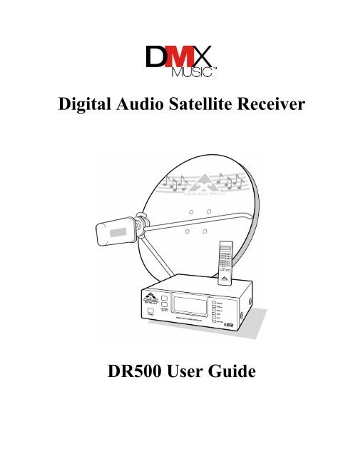
Digital Audio Satellite Receiver DR500 User Guide - Essnashville.com
Digital Audio Satellite Receiver DR500 User Guide - Essnashville.com
Digital Audio Satellite Receiver DR500 User Guide - Essnashville.com

Create successful ePaper yourself
Turn your PDF publications into a flip-book with our unique Google optimized e-Paper software.
<strong>Digital</strong> <strong>Audio</strong> <strong>Satellite</strong> <strong>Receiver</strong><br />
<strong>DR500</strong> <strong>User</strong> <strong>Guide</strong>
NOTICE<br />
This publication and its contents are proprietary to DMX and are intended solely for the contractual use of its<br />
customers for no other purpose than to operate the equipment described herein. This publication and its<br />
contents shall not be used or distributed for any other purpose and/or otherwise <strong>com</strong>municated, disclosed, or<br />
reproduced, in any way whatsoever, without the prior written consent of DMX.<br />
For the proper operation of this equipment and/or all parts thereof, the instructions in this guide must be strictly<br />
and explicitly followed by experienced personnel. All of the contents of this guide must be fully read and<br />
understood prior to operating any of the equipment, or parts thereof. FAILURE TO COMPLETELY READ<br />
AND FULLY UNDERSTAND AND FOLLOW ALL OF THE CONTENTS OF THIS GUIDE PRIOR<br />
TO OPERATING THIS EQUIPMENT, OR PARTS THEREOF, MAY RESULT IN DAMAGE TO THE<br />
EQUIPMENT, OR PARTS THEREOF, AND TO ANY PERSONS INSTALLING AND/OR<br />
OPERATING THE SAME.<br />
DMX does not assume any liability arising out of the application or use of any products, <strong>com</strong>ponent parts,<br />
circuits, software, or firmware described herein. DMX further does not convey any license under its patent,<br />
trademark, copyright, or <strong>com</strong>mon-law rights nor the similar rights of others. DMX further reserves the right to<br />
make any changes in any products, or parts thereof, described herein without notice.<br />
© Copyright 1999 <strong>Digital</strong> Music Express<br />
This equipment has been tested and found to <strong>com</strong>ply with the limits for a Class A digital device, pursuant to<br />
Part 15 of the FCC Rules. These limits are designed to provide reasonable protection against harmful<br />
interference. This equipment generates, uses, and can radiate radio frequency energy and, if not installed and<br />
used in accordance with the instructions, may cause harmful interference to radio <strong>com</strong>munications. However,<br />
there is no guarantee that interference will not occur in a particular installation. If this equipment does cause<br />
harmful interference to radio or television reception, which can be determined by turning the equipment off and<br />
on, the user is encouraged to try to correct the interference by one or more of the following measures:<br />
• Reorient or relocate the receiving antenna.<br />
• Increase the separation between the equipment and receiver.<br />
• Connect the equipment into an outlet on a circuit different from that to which the receiver is<br />
connected.<br />
• Consult the dealer or an experienced radio/TV technician for help.<br />
CAUTION: Any changes or modifications not expressly approved by DMX could void the user’s authority to<br />
operate the equipment.<br />
WARNING<br />
Shock Hazard!<br />
Do Not Open The <strong>DR500</strong> Equipment!<br />
Service Only By DMX!<br />
Gefährliche Spannung!<br />
Öffnen des Gerätes und Service nur durch DMX!<br />
The <strong>DR500</strong> contains no user-serviceable parts. Do not attempt to service this product yourself.<br />
Any attempt to do so will negate any and all warranties.<br />
To reduce the risk of fire or electric shock, do not expose this appliance to rain or moisture.
CAUTION<br />
RISK OF ELECTRIC SHOCK<br />
DO NOT OPEN<br />
CAUTION: To Reduce The Risk Of Electric Shock,<br />
Do Not Remove Cover (Or Back).<br />
No <strong>User</strong>-Serviceable Parts Inside.<br />
Refer Servicing To Qualified Service Personnel.<br />
Précautions: Pour éviter toute décharge électrique, ne pas enlever le couvercle. Les pieces a l’interieur ne sont pas<br />
reparables. Faire appel uniquement á un personnel qualifié.<br />
This symbol is intended to alert the user to the presence of uninsulated<br />
“dangerous voltage” within the product’s enclosure that may be of sufficient<br />
magnitude to constitute a risk of electric shock to persons.<br />
This symbol is intended to alert the user to the presence of important<br />
operating and maintenance (servicing) instructions in the literature<br />
ac<strong>com</strong>panying the appliance.<br />
‘Dolby’ and the ‘Double-D’ symbol are trademarks of Dolby Laboratories Licensing<br />
Corporation. AC-3 digital audio system manufactured under license from Dolby<br />
Laboratories Licensing Corporation.
Introduction<br />
Table of Contents<br />
Important Information .............................................................................................................. ix<br />
Getting Started ......................................................................................................................... ix<br />
Section 1: System Overview and Component Descriptions<br />
System Features .......................................................................................................................12<br />
What is DMX? .........................................................................................................................12<br />
DBS System Overview.............................................................................................................13<br />
<strong>DR500</strong> System Components ....................................................................................................15<br />
<strong>DR500</strong> <strong>Digital</strong> <strong>Audio</strong> <strong>Satellite</strong> <strong>Receiver</strong> ..................................................................15<br />
<strong>DR500</strong> Front Panel ...................................................................................15<br />
<strong>DR500</strong> Back Panel....................................................................................16<br />
DMR Remote Control Units.....................................................................................17<br />
DMR-22 Remote Control .........................................................................18<br />
DMR-28 DMX/DJ Remote Control..........................................................19<br />
Additional <strong>DR500</strong> <strong>Receiver</strong>s....................................................................................................20<br />
Section 2: Installation and Connections<br />
Before You Begin ....................................................................................................................20<br />
<strong>DR500</strong> Shipment Checklist �..............................................................................................21<br />
Choosing a Good Location.......................................................................................................23<br />
Safety Precautions....................................................................................................................23<br />
Connecting the <strong>DR500</strong> to Your <strong>Audio</strong> System ........................................................................24<br />
Connection <strong>Guide</strong>lines .............................................................................................24<br />
Connecting the <strong>DR500</strong> to Your Stereo System ........................................................25<br />
Connecting the <strong>DR500</strong> to Your Monaural System...................................................26<br />
If the <strong>Audio</strong> Equipment Has a Direct <strong>Digital</strong> Coaxial Input.....................................26<br />
Antenna Installation and Alignment.........................................................................................27<br />
Connecting Multiple <strong>Receiver</strong>s to One Antenna......................................................................28<br />
Re<strong>com</strong>mended Equipment .......................................................................................................28<br />
<strong>DR500</strong> (E-4)<br />
Rev. C 10/94
Section 3: Getting Started and Basic Operations<br />
Section Topics............................................................................................................................1<br />
Starting up the <strong>DR500</strong>................................................................................................................3<br />
Turning the <strong>DR500</strong> ON and OFF...............................................................................................4<br />
Basic Operational Information ...................................................................................................4<br />
Correcting Errors........................................................................................................................5<br />
Checking the Clock ....................................................................................................................5<br />
Setting the Volume.....................................................................................................................5<br />
Muting the Volume ....................................................................................................................6<br />
Selecting a Channel....................................................................................................................7<br />
Front Panel Channel Selection ...................................................................................7<br />
Remote Control Channel Selection ............................................................................7<br />
Recalling a Channel ...................................................................................................................8<br />
Scanning Channels .....................................................................................................................8<br />
DMX/DJ Functions ....................................................................................................................8<br />
Section 4: Advanced Operations<br />
Viewing Current <strong>Audio</strong> Information ..........................................................................8<br />
Viewing the Time.......................................................................................................9<br />
Section Topics............................................................................................................................1<br />
Forced Tune Events....................................................................................................................3<br />
Setting Forced Tune Events........................................................................................3<br />
Checking Forced Tune Events....................................................................................4<br />
Clearing Forced Tune Events .....................................................................................4<br />
Local Channel Management.......................................................................................................5<br />
Deleting Authorized Channels....................................................................................5<br />
Adding Authorized Channels .....................................................................................5<br />
Setting the Dynamic Range........................................................................................................6<br />
Checking Dynamic Range Settings............................................................................................7<br />
Clearing the Dynamic Range .....................................................................................................7<br />
Setting the Dynamic Range Global Default ...............................................................................7<br />
Setting the Transponder Frequency............................................................................................8<br />
Checking the Transponder Frequency........................................................................................9<br />
Checking Signal Quality ............................................................................................................9<br />
Front Panel Lockout.................................................................................................................11<br />
Setting the Front Panel Lockout ...............................................................................11<br />
Clearing the Front Panel Lockout.............................................................................11<br />
DMX/DJ Functions ..................................................................................................................11<br />
<strong>DR500</strong> (E-5)<br />
Rev. C 10/94
Checking the <strong>DR500</strong>’s ID Number ..........................................................................11<br />
Checking the <strong>DR500</strong>’s Status...................................................................................12<br />
Section 5: Maintenance and Troubleshooting<br />
Section 6: Specifications<br />
Maintenance ...............................................................................................................................1<br />
Cleaning the <strong>DR500</strong> <strong>Receiver</strong>....................................................................................................1<br />
Troubleshooting Tips .................................................................................................................1<br />
Appendix A: Warranty and Repair Information<br />
Warranty Statement ...................................................................................................................................1<br />
Return Procedures ⎯ DMX Affiliates.......................................................................................................3<br />
Appendix B: <strong>DR500</strong> Reference Sheet<br />
Appendix C: DR501 <strong>User</strong> Manual Addendum<br />
<strong>DR500</strong> (E-6)<br />
Rev. C 10/94
Wel<strong>com</strong>e to the world of premier digital audio service provided by DMX. This guide is your handbook for<br />
using the <strong>DR500</strong> <strong>Digital</strong> <strong>Audio</strong> <strong>Satellite</strong> <strong>Receiver</strong> and the DMR-22 and DMR-28 DMX/DJ remote control<br />
units.<br />
The sections in this guide provide step-by-step instructions for a variety of tasks and activities, including<br />
<strong>DR500</strong> system connections, channel scanning and selection, setting forced tune times and dynamic ranges,<br />
and instantaneous viewing of programming information.<br />
These exciting options, <strong>com</strong>bined with up to 120 available channels delivering <strong>com</strong>mercial-free, CDquality<br />
music, provide you the:<br />
• Variety to select music formats that meet your individual business image and needs<br />
• Flexibility to create tailored music programs for multiple environments, which you can vary by<br />
the hour, day, week, or season<br />
• Ability to maintain <strong>com</strong>plete local control over your music<br />
Important Information<br />
Throughout this guide you will find two symbols designed to help you identify important information.<br />
These symbols are:<br />
The note identifies information for the proper operation of your equipment, including<br />
helpful hints, shortcuts, or important reminders.<br />
The exclamation point identifies information that requires careful attention in<br />
order to prevent equipment damage and/or injury to the operator.<br />
Getting Started<br />
Before you begin using the <strong>DR500</strong> <strong>Receiver</strong>, you need to:<br />
• Install the DMX/DBS receiver and equipment, which is generally done by your local<br />
DMX affiliate or a professional installer.<br />
If your DMX/DBS receiver and equipment have not been installed, refer to Section 2:<br />
Installation.<br />
• Read the appropriate sections of this <strong>User</strong> <strong>Guide</strong> as noted below.<br />
Do not plug in the <strong>DR500</strong> <strong>Receiver</strong> until you have connected the system and read<br />
Section 3: Basic Operations.<br />
If you are new to satellite <strong>com</strong>munications or are unfamiliar with either the <strong>DR500</strong> or the remote control,<br />
you should read the following sections before unpacking or operating this product:<br />
• Section 1 for an overview of the DMX/DBS system and equipment<br />
• Section 2 helps you get started and contains a full set of <strong>DR500</strong> connection procedures<br />
• Section 3 for <strong>DR500</strong> start-up and basic operations<br />
• Section 5 to review maintenance procedures or if you encounter difficulties and need<br />
troubleshooting information<br />
• Other sections as needed<br />
<strong>DR500</strong> (E-7)<br />
Rev. C 10/94
If you are an experienced user familiar with the <strong>DR500</strong> and its remote control, you may wish to review the<br />
following sections before unpacking or operating this product:<br />
• Section 1 for an overview of the DMX/DBS system and equipment<br />
• Section 3 for <strong>DR500</strong> start-up and to review basic operations<br />
• Section 4 for advanced operations<br />
• Appendix E to use the <strong>DR500</strong> Reference Sheet<br />
• Other sections as needed<br />
<strong>DR500</strong> (E-8)<br />
Rev. C 10/94
<strong>DR500</strong> Reference<br />
<strong>DR500</strong> General Functions and Commands<br />
Channel<br />
Recall Press LAST.<br />
Scan Press SCAN.<br />
Select Enter the channel number using the NUMERIC keys.<br />
⎯OR⎯<br />
Use the TUNEÙ or TUNEÚ keys.<br />
Locally Managed Channels<br />
Add Tune to the desired channel.<br />
Press PRESET 940.<br />
Delete Tune to the desired channel.<br />
Press PRESET 950.<br />
Clock<br />
Check Press PRESET 100.<br />
Dynamic Range<br />
Check Tune to the desired channel.<br />
Press PRESET 110.<br />
Clear Press PRESET 510.<br />
Clears all dynamic range settings from memory.<br />
Set Tune to the desired channel.<br />
Press PRESET 910.<br />
Enter the dynamic range code and press STORE.<br />
Global Press PRESET 960.<br />
Enter the dynamic range code and press STORE.<br />
Forced Tune Events<br />
Check Tune to the desired channel.<br />
Press PRESET 130.<br />
Clear Press PRESET 530.<br />
Clears all forced tune event settings from memory.<br />
Set Tune to the desired channel.<br />
Press PRESET 930.<br />
Enter the hour and press STORE.<br />
Signal Quality<br />
Press PRESET 180.<br />
Press any key to clear display.<br />
Transponder Frequency<br />
Check Press PRESET 120.<br />
Set Press PRESET 920.<br />
Enter the transponder frequency and press STORE.<br />
<strong>DR500</strong> (E-9)<br />
Rev. C 10/94
<strong>DR500</strong> Reference<br />
Volume<br />
Set Adjust the volume using the controls on your stereo system.<br />
Mute Press MUTE.<br />
To return to normal volume, press MUTE again.<br />
DMX/DJ View Functions and Commands<br />
<strong>Audio</strong> Info. Press VIEW.<br />
Press MORE to see additional information.<br />
<strong>DR500</strong> Status Press PRESET 150 and press VIEW.<br />
Press MORE to see additional information.<br />
Time Press PRESET 100 and press VIEW.<br />
Unit ID Press PRESET 190 and press VIEW.<br />
<strong>DR500</strong> PRESET Commands and Functions<br />
PRESET 100 Check the <strong>DR500</strong> clock.<br />
PRESET 110 Check the dynamic range for a selected channel.<br />
PRESET 120 Check transponder frequency.<br />
PRESET 130 Check the forced tune event for a selected channel.<br />
PRESET 150 Check status of <strong>DR500</strong>.<br />
PRESET 160 Toggle LNB Power Supply On/Off.<br />
PRESET 180 Check the signal quality.<br />
PRESET 190 Check <strong>DR500</strong> Unit ID Number.<br />
PRESET 310 Toggle Generation of Pink Noise On/Off.<br />
PRESET 510 Clear all dynamic range settings from memory.<br />
PRESET 530 Clear all forced tune event settings from memory.<br />
PRESET 910 Set the dynamic range for a selected channel.<br />
PRESET 920 Set transponder frequency.<br />
PRESET 930 Set the forced tune event for a selected channel.<br />
PRESET 940 Add authorized channels.<br />
PRESET 950 Delete authorized channels.<br />
PRESET 960 Set global dynamic range.<br />
PRESET 970 Front panel lockout.<br />
PRESET 975 Volume control.<br />
<strong>DR500</strong> (E-10)<br />
Rev. C 10/94
Thank you for subscribing to <strong>Digital</strong> Music Express ® ! This section describes the Direct Broadcast <strong>Satellite</strong><br />
(DBS) receiver and equipment that are used to deliver the best in CD-quality music. The equipment<br />
includes:<br />
• <strong>Satellite</strong> dish receiving antenna, low noise block (LNB) amplifier, and connecting cable<br />
• <strong>Digital</strong> <strong>Audio</strong> <strong>Satellite</strong> <strong>Receiver</strong>, Model <strong>DR500</strong><br />
• Remote control device, Model DMR-22 or Model DMR-28 DMX/DJ<br />
<strong>DR500</strong> (E-11)<br />
Rev. C 10/94
System Features<br />
The <strong>DR500</strong> DBS <strong>Satellite</strong> <strong>Receiver</strong> is a digital audio stereo decoder which easily integrates with most<br />
stereo or monaural amplifier systems.<br />
Key system features include:<br />
• Full CD quality 20 kHz stereo<br />
• 120 stereo pairs available on one transponder<br />
• Dolby <strong>Digital</strong> <strong>com</strong>pression<br />
• Storecasting and datacasting capabilities<br />
• <strong>User</strong> and network programmable forced tune events (dayparting)<br />
• Exclusive DMX/DJ IR remote provides artist, album, and title information<br />
• Multi-zone expansion capabilities<br />
• Utilizes a small, one-meter satellite dish in most CONUS locations<br />
• <strong>Digital</strong> audio output, Sony/Philips <strong>Digital</strong> Interface Format (SPDIF)<br />
To fully appreciate the DMX/DBS service, you must have a separate stereo system that can be connected to<br />
the <strong>DR500</strong>. (For information on connecting the system, refer to “Connecting the <strong>DR500</strong> to the <strong>Audio</strong><br />
System” found in Section 2: Installation and Connections.<br />
What is DMX MUSIC?<br />
DMX MUSIC is an innovative music programming service that delivers up<br />
to 120 channels of CD-quality, <strong>com</strong>mercial-free music via satellite<br />
transmission.<br />
To provide you with this unparalleled digital sound service, DMX MUSIC<br />
uses the latest satellite technology to deliver DMX/Direct Broadcast<br />
<strong>Satellite</strong> (DBS) music to your location.<br />
<strong>DR500</strong> (E-12)<br />
Rev. C 10/94
DBS System Overview<br />
Although the use of satellites, satellite dishes, and receivers may seem <strong>com</strong>plex, the DMX/DBS service<br />
uses a highly sophisticated system that makes channel selection and local music programming easier and<br />
simpler than using a VCR. It also allows DMX to deliver music of unprecedented linearity, sonic precision,<br />
and exceptional fidelity.<br />
The DMX/DBS premiere digital audio service uses the following satellite technology:<br />
• <strong>Satellite</strong> Uplink Facility ⎯ transmits music programming to the<br />
satellite through satellite dishes<br />
• <strong>Satellite</strong> ⎯ relays the music programming signals to your satellite dish<br />
antenna<br />
• DBS <strong>Satellite</strong> Dish Antenna ⎯ receives the music programming<br />
transmitted from the satellite and relays it to the <strong>DR500</strong> <strong>Receiver</strong>. Your<br />
satellite dish can be as small as one meter and may be installed in<br />
various places on or around your location. The only constraint is that<br />
the satellite dish must be properly pointed at the satellite with no<br />
obstacles blocking the satellite signal.<br />
<strong>DR500</strong> (E-13)<br />
Rev. C 10/94
Once the DMX music programming is received at your location, your <strong>DR500</strong> <strong>Receiver</strong> and associated<br />
audio <strong>com</strong>ponents take over.<br />
COMSTREAM DR200 <strong>Digital</strong> <strong>Audio</strong> <strong>Receiver</strong> DIGITAL AUDIO<br />
1 2 3<br />
4 5 6<br />
7 8 9<br />
0<br />
• <strong>DR500</strong> <strong>Digital</strong> <strong>Audio</strong> <strong>Satellite</strong> <strong>Receiver</strong> ⎯ receives and decodes the<br />
digital audio programming information and sends it to your stereo<br />
amplifier system<br />
Additional <strong>DR500</strong> receivers provide you with additional<br />
flexibility to create tailored music programs for multiple business<br />
environments that you can vary by the hour. Additional units can<br />
be integrated into your system at any time.<br />
• Remote Control device ⎯ allows you to control and program the<br />
<strong>DR500</strong> <strong>Receiver</strong> and DBS system<br />
There are two available remote control devices: the DMR-22, which is<br />
a basic remote control device, and the DMR-28 DMX/DJ, which<br />
provides additional programming information and functionality.<br />
<strong>DR500</strong> (E-14)<br />
Rev. C 10/94
<strong>DR500</strong> System Components<br />
The <strong>DR500</strong> <strong>Digital</strong> <strong>Audio</strong> <strong>Satellite</strong> <strong>Receiver</strong> is a digital audio stereo decoder that easily integrates with<br />
most stereo or monaural amplifier systems.<br />
<strong>DR500</strong> <strong>Digital</strong> <strong>Audio</strong> <strong>Satellite</strong> <strong>Receiver</strong><br />
The <strong>DR500</strong> is the master receiver that connects to the satellite dish and your stereo or monaural amplifier<br />
system.<br />
<strong>DR500</strong> Front Panel<br />
The front panel of the <strong>DR500</strong> is used to turn the <strong>DR500</strong> on and off and manually select music channels.<br />
The front panel consists of:<br />
• Power selector ⎯ turns the <strong>DR500</strong> on and off<br />
When the <strong>DR500</strong> is Off, a small green light appears on the front panel, indicating<br />
that the <strong>DR500</strong> is able to receive any information from the DMX/DBS National<br />
Authorization Control Center.<br />
• Music channel selectors ⎯ allow you to tune to the next higher Ù or lower Ú channel<br />
If remote channel selection is preferred, use either the DMR-22 or DMR-28 DMX/DJ<br />
Remote Controls.<br />
• Front panel display ⎯ shows the current channel selection as well as other <strong>DR500</strong><br />
information<br />
• Stereo/Mono A/Mono B indicators - illuminates green to indicate either a stereo channel,<br />
or one of two mono subchannels.<br />
• Sync indicator ⎯ illuminates green when the <strong>DR500</strong> <strong>Receiver</strong> has locked onto the<br />
satellite<br />
• Authorized indicator ⎯ illuminates green when you are authorized to receive the current<br />
channel<br />
• LNB PWR ⎯ illuminates green to indicate LNB power is enabled. No illumination<br />
indicates LNB power is disabled. Blinking indicates a problem with the LNB power<br />
supply. (For more information, refer to Section 5: Maintenance and Troubleshooting.)<br />
<strong>DR500</strong> (E-15)<br />
Rev. C 10/94
<strong>DR500</strong> Back Panel<br />
The back panel of the <strong>DR500</strong> has a variety of connectors that are used to link the satellite dish to the<br />
<strong>DR500</strong> and your audio system to the <strong>DR500</strong>.<br />
The back panel consists of:<br />
• Power Input ⎯ attaches the <strong>DR500</strong> to a 120 VAC wall mount supply<br />
• RF IN connector ⎯ attaches the <strong>DR500</strong> <strong>Receiver</strong> to your local satellite dish<br />
• Mono Out connector ⎯ attaches the <strong>DR500</strong> to a monaural receiver or amplifier<br />
• Stereo Out connectors ⎯ attaches the <strong>DR500</strong> to a stereo receiver or amplifier. Left is coded<br />
white; right is coded red.<br />
• <strong>Digital</strong> Out connector (standard Sony/Philips <strong>Digital</strong> Interface Format [SPDIF] coaxial output;<br />
coded black) ⎯ attaches the <strong>DR500</strong> to a digital input of audio equipment that has a coaxial digital<br />
input.<br />
• Data/Control connector ⎯ for PC control and diagnostics<br />
• Serial ID number/bar code label — lists the serial number for this unit<br />
<strong>DR500</strong> (E-16)<br />
Rev. C 10/94
DMR Remote Control Units<br />
To select music channels remotely, you can use either the DMR-22 or DMR-28 DMX/DJ remote control<br />
units. Both remote control models have the following features:<br />
• Individual channel selection keys that allow you to move through the authorized channels one<br />
channel at a time either up or down<br />
• Preset channel selection key that allows you to enter special music programming information<br />
• Scan key that allows you to step through each authorized channel, each playing for five<br />
seconds<br />
• Mute function that allows you to turn the audio on and off<br />
• Last channel recall function that allows you to return to the previously selected channel<br />
To use either remote control unit, point it toward your <strong>DR500</strong> <strong>Receiver</strong> and press the appropriate keys. The<br />
remote control units can be used at distances of up to 10 meters (32 feet) while you are directly in front of<br />
and in a straight line to the <strong>DR500</strong> <strong>Receiver</strong>.<br />
Communication between the remote control and <strong>DR500</strong> will be impaired if there are obstructions blocking<br />
the transmission or if the remote control is not directed straight at the <strong>DR500</strong>. If the remote control fails to<br />
operate, refer to Section 5: Maintenance and Troubleshooting.<br />
<strong>DR500</strong> (E-17)<br />
Rev. C 10/94
DMR-22 Remote Control<br />
The DMR-22 remote control unit is described below.<br />
Turns the DR200<br />
on and off<br />
Tune to any<br />
channel<br />
Recalls your last<br />
channel selection<br />
Mutes the audio<br />
MUSIC<br />
POWER ID STORE PRESET<br />
1 2 3<br />
4<br />
7 8 9<br />
TV<br />
5<br />
0<br />
6<br />
LAST<br />
MUTE VOL VOL<br />
TUNE<br />
TUNE<br />
SCAN<br />
Use with the<br />
number keys to<br />
store a preset<br />
entry<br />
Use to enter<br />
special settings<br />
Tunes to the next<br />
higher authorized<br />
channel<br />
Tunes to the next<br />
lower authorized<br />
channel<br />
Steps through<br />
your authorized<br />
channels (each<br />
plays for five<br />
seconds)<br />
Turns the<br />
volume up<br />
Turns the<br />
volume down<br />
Only the keys indicated operate the <strong>DR500</strong> <strong>Receiver</strong>. The<br />
other remote control keys have no <strong>DR500</strong>-associated<br />
functions.<br />
<strong>DR500</strong> (E-18)<br />
Rev. C 10/94
DMR-28 DMX/DJ Remote Control<br />
In addition to the basic features, the DMX/DJ provides instant viewing of the following information for<br />
each music selection:<br />
• Title • Album • Composer<br />
• Artist • Record label • Album ID number<br />
The DMX/DJ also displays <strong>DR500</strong> operation information, help messages, and low battery indication. The<br />
DMX/DJ remote control is described below.<br />
Selects DMX<br />
mode for<br />
DR200 control<br />
Turns the DR200<br />
on and off<br />
Music ID (future use)<br />
Tunes to any<br />
authorized channel,<br />
and up to ten preset<br />
channels<br />
Mutes the audio<br />
MODE TITLE<br />
CABLE<br />
POWER BUY SLEEP FAVORITE<br />
POWER<br />
MENU<br />
1<br />
4<br />
DMX<br />
5<br />
7 8 9<br />
0<br />
VIEW<br />
ID STORE PRESET<br />
SELECT DISPLAY<br />
TV SCAN<br />
2 3 TUNE<br />
MUTE VOL VOL<br />
6<br />
MORE<br />
TUNE<br />
LAST<br />
DMX/DJ LCD display<br />
shows operations, DMX<br />
program information, help<br />
messages, and low<br />
battery indicator<br />
Use with the number keys<br />
to store a preset entry<br />
Retrieves DMX program<br />
title and other information<br />
Scrolls through additional<br />
DMX program information<br />
Use with the number keys<br />
to enter preset <strong>com</strong>mands<br />
Steps through your<br />
authorized channels (each<br />
plays for five seconds)<br />
Tunes to the next higher<br />
authorized channel<br />
Tunes to the next lower<br />
authorized channel<br />
Recalls your last channel<br />
selection<br />
Turns the volume up<br />
Turns the volume down<br />
The DMX/DJ must be in DMX mode (press the DMX key) to<br />
enter <strong>com</strong>mands and operate the <strong>DR500</strong> <strong>Receiver</strong>. When the<br />
DMX/DJ is in DMX mode, DMX appears in the remote's<br />
display.<br />
The volume control keys on the remote control may be<br />
inactive or off. To make these keys active, press PRESET<br />
975.<br />
Only keys indicated operate the <strong>DR500</strong>. Other keys have no<br />
<strong>DR500</strong>-associated functions.<br />
<strong>DR500</strong> (E-19)<br />
Rev. C 10/94
Additional <strong>DR500</strong> <strong>Receiver</strong>s<br />
Additional <strong>DR500</strong> receivers can be added to your system at any time. Each receiver allows you to select<br />
and play one different DMX music channel on a separate audio system. This provides additional stereo<br />
music channels to cover other locations or zones.<br />
Two or more <strong>DR500</strong> <strong>Receiver</strong>s may be connected to one antenna to provide<br />
different music channels via separate audio systems. For additional information<br />
regarding the connection of multiple receivers to one antenna, refer to Section 2.<br />
<strong>DR500</strong> (E-20)<br />
Rev. C 10/94
This section helps you set up and connect your <strong>DR500</strong> system. It provides:<br />
• <strong>DR500</strong> shipment checklist<br />
• Tips on selecting the best location for your system<br />
• Step-by-step instructions for connecting the <strong>DR500</strong> <strong>Receiver</strong> to your audio system<br />
Before You Begin<br />
Before you begin using your <strong>DR500</strong>, it is assumed that the DMX/DBS receiving equipment has been<br />
professionally installed, which includes:<br />
• Setting up the satellite dish and its LNB, correctly positioning<br />
the dish so that it is pointed at the satellite, and connecting it to<br />
the <strong>DR500</strong> <strong>Receiver</strong> (For additional information, refer to<br />
Appendices B and C.)<br />
• Placing batteries in the remote control unit to allow remote<br />
control operation<br />
<strong>DR500</strong> (E-21)<br />
Rev. C 10/94
<strong>DR500</strong> Shipment Checklist �<br />
The <strong>DR500</strong> and its <strong>com</strong>ponents are shipped in custom-designed, reinforced cardboard cartons. To ensure<br />
that the system is protected during opening, use a cutting tool that extends less than ½ inch into the carton.<br />
Keep the carton and original packaging to return a unit for repair, in the unlikely<br />
event of a failure.<br />
After the carton is opened, carefully remove the <strong>DR500</strong> and all system <strong>com</strong>ponents and check the<br />
following items:<br />
� Visually inspect the system to ensure that no physical damage has occurred during<br />
shipping.<br />
� Verify that all standard items were received. Standard items include:<br />
• One <strong>DR500</strong> <strong>Digital</strong> <strong>Audio</strong> <strong>Satellite</strong> <strong>Receiver</strong><br />
• One Wall Mount Power Supply<br />
• One stereo cable (RCA plug type, approximately one meter long)<br />
• This <strong>User</strong> <strong>Guide</strong><br />
<strong>DR500</strong> (E-22)<br />
Rev. C 10/94
Choosing a Good Location<br />
There are a few items to consider when selecting a location for your <strong>DR500</strong> <strong>Receiver</strong>. Observe the<br />
following Safety Precautions:<br />
Safety Precautions<br />
Carefully read and follow all safety, use, and operating instructions before<br />
operating the <strong>DR500</strong>. Heed all warnings and cautions contained in this<br />
<strong>User</strong> <strong>Guide</strong>. Retain these safety, use, and operating instructions for future<br />
reference.<br />
FOLLOW STARTUP PROCEDURE<br />
Do not plug in the <strong>DR500</strong> <strong>Receiver</strong> until you have connected the system and read Section 3: Basic<br />
Operations.<br />
PROVIDE A SAFE LOCATION<br />
Place the <strong>DR500</strong> on a stable surface of sufficient size and strength, where it will not be jarred, hit, or<br />
pushed off its surface. Ensure that all cables and cords are out of the way and will not be tripped over, as<br />
this could cause personal injury or serious damage to the <strong>DR500</strong>.<br />
AVOID WATER AND MOISTURE<br />
Do not expose the <strong>DR500</strong> to any liquids, which are often found in flower vases, coffee cups, rain from<br />
open windows, etc. If the <strong>DR500</strong> is exposed to any liquid, contact your DMX affiliate, as serious damage<br />
could occur to the <strong>DR500</strong> or its <strong>com</strong>ponents.<br />
AVOID HEAT, HUMIDITY, AND DUST<br />
To avoid internal damage, the <strong>DR500</strong> should be placed away from all heat sources, including radiators,<br />
heater ducts, etc., out of direct sunlight, and away from high humidity, excessive dust, or mechanical<br />
vibrations, that can cause damage to internal parts.<br />
PROVIDE ADEQUATE VENTILATION<br />
To avoid overheating, place the <strong>DR500</strong> on a smooth, hard surface that has 2" of clearance around the unit<br />
and adequate air circulation. If the <strong>DR500</strong> is placed in a closed area, such as a bookcase or rack, ensure<br />
that proper ventilation is provided.<br />
Never place the <strong>DR500</strong> on a soft surface, such as a rug, sofa, or bed, that would obstruct the required air<br />
flow into the <strong>DR500</strong> ventilation slots.<br />
USE CORRECT POWER SOURCE<br />
Operate the wall mount power supply for the <strong>DR500</strong> from a 120 V, 60 Hz outlet only. Take care not to<br />
overload wall outlets or extension cords, as this increases the risk of fire or electrical shock.<br />
ROUTE POWER CORDS SAFELY<br />
Route power cords so they are not walked on or pinched. Pay particular attention to cords and connections<br />
at the plugs, receptacles (such as power strips), and the point where they exit from the <strong>DR500</strong> and attach to<br />
other equipment. Do not place any items on or against power cords.<br />
USE APPROVED ATTACHMENTS ONLY<br />
Use only DMX-approved attachments with the <strong>DR500</strong> <strong>Receiver</strong>..<br />
<strong>DR500</strong> (E-23)<br />
Rev. C 10/94
Connecting the <strong>DR500</strong> to Your <strong>Audio</strong> System<br />
If your <strong>DR500</strong> system has not been professionally installed, if you have disconnected your <strong>DR500</strong><br />
<strong>Receiver</strong>, or if you are adding a <strong>com</strong>ponent, refer to the following steps and diagrams to help you connect<br />
your system.<br />
If you have questions or need assistance connecting any <strong>com</strong>ponents to your <strong>DR500</strong>, please contact your<br />
DMX MUSIC Affiliate Sales Support team.<br />
To connect multiple <strong>DR500</strong> <strong>Receiver</strong>s to one antenna, refer to Appendix D.<br />
Connection <strong>Guide</strong>lines<br />
It is important that you follow these guidelines when making any <strong>DR500</strong> system connection:<br />
• Do not plug the <strong>Receiver</strong> into an AC outlet until all connections have<br />
been made and you have read the Startup procedures in Section 3:<br />
Basic Operations.<br />
• Turn the audio system amplifier OFF and the volume <strong>com</strong>pletely<br />
down.<br />
• Connections should be finger-tight only; never use pliers or a wrench.<br />
• The <strong>DR500</strong> <strong>Receiver</strong> wall mount power supply is not polarized, and<br />
any orientation on the wall or power strip is acceptable. When<br />
mounting to a standard dual outlet, a screw is provided to prevent<br />
accidental removal of the wall mount power supply.<br />
• The <strong>DR500</strong> <strong>Receiver</strong> should not be plugged into an AC socket like<br />
those found on the rear of audio amplifiers.<br />
• Once the <strong>DR500</strong> is connected, turned on, and receiving the satellite<br />
signal, it should remain plugged in to an unswitched (on) AC outlet so<br />
that it can receive any programming updates, authorization <strong>com</strong>mands,<br />
and information from the DMX/DBS National Authorization Control<br />
Center.<br />
If the <strong>DR500</strong> will not be used for extended periods of time, it should<br />
be turned off using the front panel power switch only. It should not be<br />
unplugged nor have its AC power turned off.<br />
<strong>DR500</strong> (E-24)<br />
Rev. C 10/94
Connecting the <strong>DR500</strong> to Your Stereo System<br />
To connect the <strong>DR500</strong> to a stereo system, refer to the figure below and the following instructions.<br />
1. Make sure the stereo amplifier is OFF and the volume is turned <strong>com</strong>pletely down.<br />
2. Connect the RCA stereo cables to the L(eft) and R(ight) STEREO jacks on the back<br />
of the <strong>DR500</strong>.<br />
3. Connect the other end of the RCA cables to any high-level input on your stereo<br />
equipment EXCEPT the phonograph input.<br />
Remember to match left and right channels.<br />
Do not connect the RCA cables from the <strong>DR500</strong> to the PHONO input of audio<br />
equipment. Any line level input such as AUX, CD, DAT, TAPE, VIDEO, or<br />
VCR can be used for the <strong>DR500</strong> output.<br />
4. Plug the <strong>DR500</strong> into an AC outlet.<br />
5. Continue on to Section 3: Basic Operations.<br />
<strong>DR500</strong> (E-25)<br />
Rev. C 10/94
Connecting the <strong>DR500</strong> to Your Monaural System<br />
To connect the <strong>DR500</strong> to a monaural system, refer to the figure below and the following instructions.<br />
1. Make sure<br />
the monaural amplifier is OFF and the volume is turned <strong>com</strong>pletely down.<br />
2. Connect an RCA cable to the MONO jack on the back of the <strong>DR500</strong>.<br />
3. Connect the other end of the RCA cable to any available input on the monaural<br />
equipment EXCEPT the phonograph input.<br />
Do not connect the RCA cables from the <strong>DR500</strong> to the PHONO input of<br />
audio equipment. Any line level input such as AUX, CD, DAT, TAPE,<br />
VIDEO, or VCR can be used for the <strong>DR500</strong> output.<br />
4. Plug the <strong>DR500</strong> into an AC outlet.<br />
5. Continue on to Section 3: Basic Operations.<br />
If the <strong>Audio</strong> Equipment Has a Direct <strong>Digital</strong> Coaxial Input<br />
To connect the <strong>DR500</strong> to audio equipment with direct digital input, refer to the figure below and<br />
the following instructions.<br />
Connect a shielded RCA cable (not provided) from the DIGITAL OUT connector on the <strong>DR500</strong><br />
to the coaxial DIGITAL INPUT connector on the audio equipment. (See your stereo manual for<br />
specific requirements.) The default output format is un<strong>com</strong>pressed PCM; it may optionally be<br />
configured as Dolby <strong>Digital</strong>.<br />
<strong>DR500</strong> (E-26)<br />
Rev. C 10/94
Antenna Installation and Alignment<br />
It is re<strong>com</strong>mended that the <strong>Satellite</strong> dish antenna be installed by your local DMX Affiliate. It is imperative<br />
that the dish be securely and safely mounted, and pointed accurately at the <strong>Satellite</strong>. Brief instructions are<br />
presented here for <strong>com</strong>pleteness.<br />
<strong>Satellite</strong> Dish Installer: Ground the RF input cable to the building grounding system as close as possible<br />
to the point of building entry. Refer to the National Electric Code (NEC) Article 820-40.<br />
The following steps describe the process to properly set up, position, and connect the antenna using the<br />
<strong>DR500</strong> <strong>Receiver</strong>:<br />
1. Determine the proper block converter and feed horn polarity adjustment for your<br />
area.<br />
2. Assemble the satellite dish antenna.<br />
3. Locate the antenna in an area with an unobstructed line of sight to the satellite<br />
coordinates (azimuth and elevation) for your area.<br />
For information relating to satellite location and coordinates, antenna alignment, and<br />
signal acquisition, contact your DMX affiliate.<br />
4. Pre-position the antenna to the correct azimuth and elevation coordinates by using a<br />
<strong>com</strong>pass and inclinometer.<br />
5. Pre-position the LNB to the indicated polarity setting.<br />
6. Locate the <strong>DR500</strong> <strong>Receiver</strong> within visual range of the antenna.<br />
7. Connect a 75 ohm coaxial cable (RG-6, typical) from the output of the LNB to the<br />
<strong>Receiver</strong> RF IN connector.<br />
8. Connect 120 VAC power to the <strong>DR500</strong> <strong>Receiver</strong> – do not turn it on.<br />
Improvise a temporary sun shade over the <strong>DR500</strong> front panel as the LED displays may be<br />
difficult to read in direct sunlight.<br />
9. Place the receiver in signal strength mode by depressing the power, channel up, and<br />
channel down buttons simultaneously. Alternatively, this may be done with the<br />
remote control using Preset 180.<br />
− The display reads nL, signifying it is not locked.<br />
– Channel 1 flashes on the front panel display indicating the receiver is muted<br />
– AUTH LED is Off unless the receiver is already authorized<br />
– SYNC LED is Off and remains so until the satellite is acquired<br />
The signal strength level numbers are preceded by a minus sign (-) to differentiate them from<br />
a music channel number. Signal Quality readings vary from -00 (the strongest level) to<br />
approximately -80 (weakest level) before losing the satellite lock nL.<br />
Rock the dish slowly from side to side and up/down around the nominal position. When the<br />
<strong>Satellite</strong> has been located, the display will read out a negative number representing signal<br />
strength and the Sync light will illuminate. Carefully move the dish to maximize signal, at<br />
which time the readout will be the least negative (closest to zero). Tighten the bolts and<br />
check that signal strength has not been disturbed by tightening the bolts.<br />
<strong>DR500</strong> (E-27)<br />
Rev. C 10/94
Connecting Multiple <strong>Receiver</strong>s to One Antenna<br />
Multiple <strong>DR500</strong> <strong>Receiver</strong>s can be connected to one antenna. However, to avoid damage to either the antenna LNB and<br />
<strong>DR500</strong> <strong>Receiver</strong>, the following items must be used:<br />
• Correct splitter(s)<br />
• Proper line amplifiers<br />
Line amplifiers may be required when using a signal splitter and/or when long coaxial cable runs<br />
are required from antenna to receiver. All splitters and line amplifiers should be rated for satellite<br />
IF processing with a minimum bandwidth of 950 MHz to 1450 MHz.<br />
Since power is delivered to the LNB and line amplifier by the <strong>DR500</strong> <strong>Receiver</strong> (18 VDC via RF IN connector), splitters<br />
should have one DC power passing port. All other ports must block DC or have equivalent circuitry that only permits<br />
one of the <strong>DR500</strong> <strong>Receiver</strong>s to power the LNB. Never connect via power passing splitters. Additionally, the receivers<br />
not delivering power to the LNB should have their LNB power output switched OFF using Preset 160. Failure to do so<br />
may result in severe damage to the antenna LNB and the <strong>DR500</strong> <strong>Receiver</strong>s<br />
The line amplifier should be inserted just prior to the input of the splitter (not after the antenna LNB). For<br />
best performance line amplifiers are typically inserted every 150 feet.<br />
Re<strong>com</strong>mended Equipment<br />
The following equipment is re<strong>com</strong>mended when multiple receivers are connected to one antenna:<br />
• High frequency splitters<br />
− QINTAR HFS-2 and HFS-4. Two and four port splitters that pass power from one<br />
port.<br />
− QINTAR HFS-2WB and HFS-4WB. Two and four port 5 to 2050 MHz wide band<br />
splitters with a built in zener diode circuit to protect DC return back to the <strong>DR500</strong><br />
<strong>Receiver</strong>. These splitters can be used in installations requiring power passing to only<br />
one port.<br />
• In-line satellite amplifier<br />
− QINTAR LA-2050. This line amplifier has a bandwidth of 10 to 2050 MHz. It is<br />
typically powered by the <strong>DR500</strong> <strong>Receiver</strong> 18 VDC power.<br />
• Coaxial Cable<br />
− For short runs, under 150 feet, use a 75 ohm RG-59 coaxial cable.<br />
− For cable runs over 150 feet, use higher quality RG-6 or RG-11 cable to minimize<br />
antenna signal loss and amplifier requirements.<br />
<strong>DR500</strong> (E-28)<br />
Rev. C 10/94
The <strong>DR500</strong> advanced features give you the power and flexibility to create tailored musical programs.<br />
These advanced functions include:<br />
• Forced tune programming ⎯ a channel is automatically selected and played at a specific<br />
time<br />
• Adding and deleting authorized channels<br />
• Setting the dynamic range of a particular channel or all channels ⎯ useful when DMX<br />
selections are playing in a noisy environment<br />
Section Topics<br />
This section describes the advanced functions and operation of the <strong>DR500</strong> and remote control. Advanced<br />
functions include:<br />
• Setting, checking, and clearing forced tune events<br />
• Local channel management<br />
• Setting and checking the Dynamic Range for individual channels and as a global default<br />
• Setting and checking transponder frequency<br />
• Setting and clearing the front panel lockout<br />
• DMX/DJ functions<br />
Many of these features can be programmed and controlled by the DMX DBS National Authorization<br />
Center. When you turn on your <strong>DR500</strong> and call for authorization, talk to your DMX affiliate about this<br />
service.<br />
<strong>DR500</strong> (E-29)<br />
Rev. C 10/94
Forced Tune Events<br />
Forced Tune Events allow you to easily specify at what hour a particular channel will be played. Although<br />
forced tune events sound simple, they’re actually a powerful function that provides you with a wide range<br />
of musical programming flexibility and creativity, along with local manageability.<br />
Setting Forced Tune Events<br />
The <strong>DR500</strong> allows you to program and store up to six forced tune events per day. These forced tune events<br />
can be programmed for one channel or spread across a maximum of six channels.<br />
To set a forced tune event:<br />
1. Tune to the desired channel.<br />
2. Press:<br />
PRESET 9 3 0<br />
The front panel displays two flashing zeros, indicating that the <strong>DR500</strong> is ready for<br />
you to enter the hour to tune in this channel.<br />
You specify forced tune events for the hour, on the hour (10, 11, etc.). You cannot<br />
specify a portion of an hour, such as 10:15 a.m. If you need a forced tune event to<br />
play at a specific hour and minute, contact the DMX/DBS National Authorization<br />
Control Center who will program the event for you.<br />
3. Enter the hour in 24-hour format then press STORE.<br />
For example, 8:00 p.m. would be entered as 20.<br />
# # STORE<br />
If there are less than six forced tune events programmed, the new event will be stored in memory. At the<br />
designated time, the <strong>DR500</strong> will automatically tune to the programmed channel.<br />
If you exceed the six forced tune events maximum, the <strong>DR500</strong> front panel displays FUL (full) indicating<br />
the memory is full. When FUL displays, the <strong>DR500</strong> memory must be cleared before any forced tune events<br />
can be entered. Refer to Clearing Forced Tune Events for this procedure.<br />
Pressing PRESET while entering a forced tune event exits the procedure and returns to the current<br />
channel.<br />
Checking Forced Tune Events<br />
To check the forced tune event settings for a channel:<br />
If two forced tune events are inadvertently scheduled for the same<br />
time period, the event that was set first will play.<br />
1. Tune to the desired channel.<br />
2. Press:<br />
PRESET 1 3 0<br />
<strong>DR500</strong> (E-30)<br />
Rev. C 10/94
If the current channel has no programmed forced tune events, the front panel displays three flashing<br />
dashes.<br />
⎯ ⎯ ⎯<br />
If the current channel has any programmed forced tune events, the time of the event (in 24-hour time)<br />
displays on the front panel as a flashing two-digit number. If more than one event is programmed for the<br />
channel, the front panel will scroll through all programmed events, displaying each for five seconds.<br />
Once all the forced tune events have been displayed, the front panel returns to the current channel.<br />
Clearing Forced Tune Events<br />
The <strong>DR500</strong> allows you to program and store up to six forced tune events. These forced tune events can be<br />
programmed for one channel or spread across a maximum of six channels.<br />
If you have exceeded the six forced tune events maximum, the <strong>DR500</strong> front panel displays FUL indicating<br />
the memory is full. When FUL displays, the <strong>DR500</strong> memory must be <strong>com</strong>pletely cleared before new<br />
forced tune events can be entered. To clear the <strong>DR500</strong> memory press:<br />
PRESET 5 3 0<br />
The front panel will momentarily display CLr (clear) as the <strong>DR500</strong> clears all forced tune events from<br />
memory. When the <strong>DR500</strong> has finished clearing all settings, the current channel displays.<br />
<strong>DR500</strong> (E-31)<br />
Rev. C 10/94
Local Channel Management<br />
The <strong>DR500</strong> allows you to locally manage the channels authorized to you through DMX/DBS National<br />
Authorization Control Center. From your location, you can temporarily delete an authorized channel so<br />
that it cannot be played for a specific time in your location. Then, when you decide the timing is right, you<br />
can add the authorized channel into your format again.<br />
Deleting Authorized Channels<br />
The <strong>DR500</strong> gives you local control to delete channels from your list of authorized channels. To locally<br />
delete an authorized channel:<br />
1. Tune to the desired channel.<br />
2. Press:<br />
PRESET 9 5 0<br />
The front panel flashes dEL (delete) as the <strong>DR500</strong> marks the channel as locally deleted. In addition:<br />
• Authorization LED remains ON as this a locally deleted channel<br />
• <strong>Audio</strong> is muted for that locally deleted channel<br />
• dEL flashes on the <strong>DR500</strong> display when this channel is selected<br />
Adding Authorized Channels<br />
Just as you can locally delete an authorized channel from your local channel listing, you can also add the<br />
channels back to the list. To do this:<br />
1. Tune to the desired channel.<br />
2. Press:<br />
PRESET 9 4 0<br />
The front panel momentarily displays Add as the <strong>DR500</strong> adds the authorizes channel. In addition:<br />
• Channel you added is displayed<br />
• Authorization LED remains ON<br />
• <strong>Audio</strong> is broadcast from that locally added channel<br />
You locally manage only channels authorized by your DMX affiliate. To add<br />
authorized channels to your local listing, contact your DMX affiliate.<br />
<strong>DR500</strong> (E-32)<br />
Rev. C 10/94
Setting the Dynamic Range<br />
The <strong>DR500</strong> <strong>Receiver</strong> is shipped with all 120 channels set at full CD-quality (90 dB dynamic range). To<br />
meet your individual music needs, you have the capability of setting a different dynamic range for up to 10<br />
channels, or setting all channels to a global dynamic range default. Changing the dynamic range setting<br />
may provide a more uniform volume, or loudness, throughout your musical program. To set the dynamic<br />
range for a channel:<br />
1. Tune to the desired channel.<br />
2. Press:<br />
PRESET 9 1 0<br />
The front panel flashes the current dynamic range code for this channel. The range<br />
codes are:<br />
Front Panel<br />
Code<br />
Remote Control<br />
Code<br />
Dynamic Range<br />
Settings<br />
00 00 Full CD-quality (90 dB)<br />
01 01 80 dB range<br />
02 02 60 dB range<br />
03 03 40 dB range<br />
3. Enter the dynamic range code. Press the appropriate number (or use the TUNEÙ and<br />
TUNEÚ buttons to make your selection), then press STORE.<br />
# STORE<br />
If there are less than 10 Dynamic Range settings programmed, the new setting will be stored in memory.<br />
The <strong>DR500</strong> will automatically implement the selected dynamic range when the specified channel is tuned.<br />
If you have exceeded the 10-channel maximum, the <strong>DR500</strong> front panel displays FUL indicating the<br />
memory is full. When FUL displays, the <strong>DR500</strong> memory must be <strong>com</strong>pletely cleared before additional<br />
Dynamic Range settings can be entered. Refer to Clearing the Dynamic Range for this procedure. Pressing<br />
PRESET while entering a Dynamic Range code exits the procedure and returns the display to the current<br />
channel.<br />
Dynamic range settings specified for individual channels will override, or take<br />
precedence over, global dynamic range default settings.<br />
<strong>DR500</strong> (E-33)<br />
Rev. C 10/94
Checking Dynamic Range Settings<br />
To check the dynamic range for a specific channel:<br />
1. Tune to the desired channel.<br />
2. Press:<br />
PRESET 1 1 0<br />
The front panel flashes the current dynamic range code (00-03) for this channel. If a specific dynamic<br />
range has not been set, the front panel displays a flashing three-digit number representing the global default<br />
for that channel.<br />
Clearing the Dynamic Range<br />
The <strong>DR500</strong> allows you to program and store up to 10 channels with specific dynamic range settings. If you<br />
have exceeded the 10-channel maximum, the <strong>DR500</strong> front panel displays FUL indicating the memory is<br />
full. When FUL displays, the <strong>DR500</strong> memory must be cleared before additional dynamic range settings<br />
can be entered. To clear the <strong>DR500</strong> memory, press:<br />
PRESET 5 1 0<br />
The front panel will momentarily display CLr as the <strong>DR500</strong> clears all dynamic range settings from<br />
memory. When the <strong>DR500</strong> has finished clearing all settings, the current channel displays.<br />
Setting the Dynamic Range Global Default<br />
To set one dynamic range for all authorized channels:<br />
1. Press:<br />
PRESET 9 6 0<br />
2. Enter the dynamic range code. Press the appropriate number (or use the<br />
TUNEÙ and TUNEÚ buttons to make your selection), then press STORE.<br />
# STORE<br />
All channels are set to the specified dynamic range. To change or clear the global dynamic range default<br />
setting, repeat this procedure.<br />
<strong>DR500</strong> (E-34)<br />
Rev. C 10/94
Setting the Transponder Frequency<br />
The <strong>DR500</strong> is shipped with the transponder frequency saved in memory. It is highly unlikely that this<br />
frequency will have to be changed and should only be done upon instructions from your DMX affiliate. In<br />
the event that a new transponder frequency must be entered, follow these procedures:<br />
1. Press:<br />
PRESET 9 2 0<br />
The transponder frequency in MHz displays as a flashing three-digit code on the<br />
front panel. The transponder frequency codes and their corresponding frequencies are<br />
shown below.<br />
MHz Front Panel Codes Transponder Frequency<br />
950 to 999 950 MHz to 999 MHz<br />
000 to 450 1000 MHz to 1450 MHz<br />
2. Enter the transponder frequency using the <strong>DR500</strong> front panel codes. (For example,<br />
you enter a frequency of 1249 MHz using the code 249.) Press the appropriate<br />
number, then press STORE.<br />
# # # STORE<br />
The new transponder frequency will be stored in memory.<br />
Pressing PRESET while entering a Transponder Frequency code exits the procedure and returns to the<br />
current channel.<br />
Be careful to enter the correct frequency. The <strong>DR500</strong> will not operate if the<br />
Transponder Frequency is incorrect.<br />
<strong>DR500</strong> (E-35)<br />
Rev. C 10/94
Checking the Transponder Frequency<br />
To check the current transponder frequency, press:<br />
PRESET 1 2 0<br />
The front panel flashes the current Transponder Frequency MHz code.<br />
Checking Signal Quality<br />
The quality of the in<strong>com</strong>ing signal can be checked using the following procedures:<br />
1. Ensure that the <strong>DR500</strong> has acquired the signal ⎯ the sync indicator on the front<br />
panel will be lit.<br />
2. Press:<br />
PRESET 1 8 0<br />
– The front panel displays SS (signal strength) and then displays a dash<br />
followed by a two-digit number from 00 to 99 indicating the strength of the<br />
in<strong>com</strong>ing signal.<br />
⎯ # #<br />
The display is updated approximately twice per second. Your display may<br />
not change if the signal quality is constant.<br />
– If the <strong>DR500</strong> is not locked, nL displays on the front panel.<br />
Unlike most other <strong>DR500</strong> functions, the signal quality indicator does not automatically clear from the<br />
display. To clear the display, press any key on the remote control or the <strong>DR500</strong> front panel.<br />
<strong>DR500</strong> (E-36)<br />
Rev. C 10/94
The following table shows the <strong>DR500</strong> codes and their corresponding Eb/No levels.<br />
A code of -00, with a corresponding Eb/No level of 17 dB or greater, is the highest signal quality. A code<br />
of -68, with corresponding Eb/No levels of 5 dB or lower, is a very weak signal strength.<br />
<strong>DR500</strong> Display Code Eb/No Signal Strength<br />
-00 to -01 17 + dB<br />
-02 16 dB<br />
-04 15 dB<br />
-06 14 dB<br />
-09 13 dB<br />
-14 12 dB<br />
-20 11 dB<br />
-27 10 dB<br />
-35 09 dB<br />
-44 08 dB<br />
-52 07 dB<br />
-61 06 dB<br />
-68 05 dB<br />
-75 04 dB<br />
-80 03 dB<br />
nL not locked<br />
<strong>DR500</strong> (E-37)<br />
Rev. C 10/94
Front Panel Lockout<br />
Setting the Front Panel Lockout<br />
The <strong>DR500</strong> allows you to inhibit, or lockout, any <strong>com</strong>mand entries. To do this press:<br />
PRESET 9 7 0<br />
The front panel displays LOC indicating that the front panel has been locked. When the front panel has<br />
been locked, both the front panel and the remote control will be non-functional. The only <strong>com</strong>mand that<br />
will be accepted by the <strong>DR500</strong> is the <strong>com</strong>mand to clear the front panel lockout.<br />
Clearing the Front Panel Lockout<br />
To clear the front panel lockout, press:<br />
PRESET 9 7 0 STORE<br />
The front panel lockout <strong>com</strong>mand will be cleared and the <strong>DR500</strong> will receive all <strong>com</strong>mands through the<br />
front panel and be fully functional again.<br />
DMX/DJ Functions<br />
Checking the <strong>DR500</strong>’s ID Number<br />
Every <strong>DR500</strong> <strong>Receiver</strong> has a specific identification (ID) number which is located on the back of the<br />
<strong>DR500</strong>. To check the <strong>DR500</strong>’s ID number using the DMX/DJ, press:<br />
PRESET 1 9 0 VIEW<br />
The ten-digit ID number displays in the following format:<br />
• ID NUMBER 123-4567-890<br />
<strong>DR500</strong> (E-38)<br />
Rev. C 10/94
Checking the <strong>DR500</strong>’s Status<br />
You can periodically check the status of the <strong>DR500</strong> using the DMX/DJ.<br />
1. To check the status, press:<br />
PRESET 1 5 0 VIEW<br />
The DMX/DJ displays a variety of status messages.<br />
2. To move through the screens of information, press MORE on the DMX/DJ.<br />
MORE<br />
The <strong>DR500</strong> status messages are presented in the following tables.<br />
DMX/DJ General Status<br />
Messages<br />
Status Message Description<br />
SIG STRENGTH: ## Displays the Eb/No signal strength. For a listing of signal<br />
strength codes, refer to Signal Quality.<br />
USER DELETED: ## Displays the number of authorized channels that the user<br />
locally deleted.<br />
USER DYN RNG: ## Displays the number of channels that have a dynamic<br />
range setting.<br />
USER FORCED TN: ## Displays the number of programmed forced tune events.<br />
FREQ: ##kHz Displays the RF frequency.<br />
<strong>DR500</strong> V#.## Displays the current <strong>DR500</strong> software version.<br />
<strong>DR500</strong> (E-39)<br />
Rev. C 10/94
Front Panel Status<br />
Code<br />
DMX/DJ Status<br />
Message<br />
Individual Error Messages<br />
<strong>DR500</strong> Status<br />
000 System OK <strong>DR500</strong> is working properly<br />
001 System PLL Phased locked loop error<br />
002 System LNB Power to the low noise block (LNB) is<br />
shorted<br />
004 System NV Nonvolatile memory errors<br />
003 System PLL<br />
System LNB<br />
005 System PLL<br />
System NV<br />
006 System LNB<br />
System NV<br />
007 System PLL<br />
System LNB<br />
System NV<br />
Combined Error Messages<br />
Phased locked loop error and power to the<br />
low noise block (LNB) is shorted<br />
Phased locked loop error and nonvolatile<br />
memory errors<br />
Power to the low noise block (LNB) is<br />
shorted and nonvolatile memory errors<br />
All system errors are detected<br />
For additional information about <strong>DR500</strong> status messages, refer to Section 5: Maintenance and<br />
Troubleshooting.<br />
Maintenance<br />
The <strong>DR500</strong> <strong>Receiver</strong> and remote controls are designed to deliver years of maintenance-free, CD-quality<br />
music. The only maintenance you may need to perform is cleaning your <strong>DR500</strong> <strong>Receiver</strong> and replacing<br />
batteries in your remote control.<br />
Cleaning the <strong>DR500</strong> <strong>Receiver</strong><br />
Before cleaning the <strong>DR500</strong>, unplug it from the wall outlet. Clean the cabinet, panel, and controls with a<br />
soft cloth lightly moistened with water.<br />
Do not use any type of abrasive pads, scouring powders, liquid cleaners, aerosol cleaners, or solvents such<br />
as alcohol or benzene.<br />
<strong>DR500</strong> (E-40)<br />
Rev. C 10/94
Troubleshooting Tips<br />
The troubleshooting tips found on the following pages were designed to help you diagnose and correct<br />
minor problems in the unlikely event that you experience difficulties with your DBS <strong>DR500</strong> system.<br />
Possible problems, arranged alphabetically, are followed by solutions that should help you to troubleshoot<br />
any DBS <strong>DR500</strong> difficulties.<br />
If you try all the suggested solutions and nothing works, call your DMX affiliate, as they are equipped to<br />
diagnose and correct your DBS system and <strong>DR500</strong> <strong>Receiver</strong> problems.<br />
Problem Possible Causes Solutions<br />
Authorized indicator is<br />
NOT lit green<br />
<strong>DR500</strong> <strong>Receiver</strong> does<br />
not work<br />
<strong>DR500</strong> <strong>Receiver</strong><br />
shows a distinct<br />
change in operation or<br />
is not operating<br />
normally<br />
LNB PWR Indicator<br />
Flashing<br />
Music stops briefly or<br />
is distorted<br />
You are not authorized to receive the current<br />
channel.<br />
Tune to an authorized channel. Contact<br />
your DMX affiliate if you wish to receive<br />
the music channel.<br />
<strong>DR500</strong> is not plugged in. Check that the <strong>DR500</strong> is plugged into an<br />
AC power outlet.<br />
The AC outlet is off. Turn the AC outlet on.<br />
The AC outlet is not working. Switch the <strong>DR500</strong> power cord to another<br />
outlet. Have a professional electrician<br />
check the outlet.<br />
The AC outlet is not providing the required<br />
power. (You may be experiencing a power<br />
brown out in your area.)<br />
The DBS system is not correctly installed, the<br />
satellite dish antenna is not pointed at the<br />
satellite.<br />
Operate the <strong>DR500</strong> from a 120 V, 60 Hz<br />
outlet only. Have a professional electrician<br />
check the outlet.<br />
Check the DBS system for proper<br />
operation and that the satellite dish is in<br />
the correct position (refer to Section 1).<br />
The <strong>DR500</strong> may need to be serviced. Unplug the receiver from the wall outlet.<br />
Wait 30 seconds. Plug the <strong>DR500</strong> back<br />
into the outlet. Check the <strong>DR500</strong>’s<br />
performance. If the <strong>DR500</strong> still performs<br />
poorly, contact your DMX affiliate.<br />
The cable connecting the <strong>DR500</strong> to the satellite<br />
dish is shorted.<br />
Disconnect the cable from the unit and<br />
wait 30 seconds. If the Fault light turns<br />
off, replace the cable. If the Fault light<br />
flashes, contact your DMX affiliate.<br />
There is a problem with the satellite dish LNB. Contact your DMX affiliate.<br />
The audio signal for the particular music<br />
channel was temporarily interrupted by a<br />
technical problem.<br />
Poor satellite signal quality sometimes due to<br />
sunspots or inclement weather.<br />
The <strong>DR500</strong> was subjected to excessive<br />
vibration or movement.<br />
Select another music channel or wait for<br />
the music to begin again.<br />
Wait for the music to begin again. If this is<br />
a frequently re-occuring problem, contact<br />
your DMX affiliate.<br />
Ensure that the <strong>DR500</strong> is in an appropriate<br />
location away from vibration or movement<br />
that may cause the music to stop<br />
momentarily.<br />
<strong>DR500</strong> (E-41)<br />
Rev. C 10/94
Problem Possible Causes Solutions<br />
No sound The stereo is turned off or the volume is turned<br />
down.<br />
No sound from one<br />
speaker<br />
Remote control does<br />
not operate the <strong>DR500</strong><br />
Turn on the stereo and adjust the volume.<br />
The <strong>DR500</strong> <strong>Receiver</strong> volume is turned down. Turn the volume up on the <strong>DR500</strong><br />
<strong>Receiver</strong>.<br />
The Mute function is selected. To return to normal volume, press MUTE<br />
on your remote control.<br />
You are not authorized to receive the current<br />
channel.<br />
The <strong>DR500</strong> and stereo connectors are not<br />
correctly attached.<br />
Balance is incorrectly set or stereo/speaker<br />
connections are not correctly adjusted.<br />
The remote control is not pointed at the<br />
<strong>DR500</strong>.<br />
Tune to an authorized channel (refer to<br />
Section 3). Contact your DMX affiliate if<br />
you wish to receive the music channel.<br />
Check all <strong>DR500</strong> and stereo connections.<br />
Adjust the balance controls on your stereo<br />
and check all connectors.<br />
Point the remote control directly at the<br />
<strong>DR500</strong>. Ensure that there are no obstacles<br />
between the <strong>DR500</strong> and the remote control<br />
unit.<br />
The remote control is too far from the <strong>DR500</strong>. Move to within 10 meters of the <strong>DR500</strong>.<br />
The path between the <strong>DR500</strong> and remote<br />
control is obstructed.<br />
The DMX/DJ mode is not set to the correct<br />
mode.<br />
Remove the obstruction, point the remote<br />
control directly at the <strong>DR500</strong>.<br />
Ensure that the DMX/DJ mode is set<br />
correctly. You will see DMX appear on<br />
the DMX/DJ display (refer to Section 1).<br />
Front panel lockout is set. Unlock the front panel (refer to Section 4).<br />
The remote control batteries are run down. Replace all remote control batteries.<br />
Remote control is broken. Check that the remote control is<br />
functioning properly by performing the<br />
procedure for viewing the time on the<br />
DMX/DJ.<br />
<strong>DR500</strong> (E-42)<br />
Rev. C 10/94
Problem Possible Causes Solutions<br />
Remote control<br />
operates erratically<br />
Sync indicator is not lit<br />
green<br />
Volume control does<br />
not work<br />
The remote control is exposed to direct, bright<br />
sunlight or florescent lighting. This exposure<br />
may interfere with the remote control signal<br />
and not allow the remote and <strong>DR500</strong> to<br />
<strong>com</strong>municate.<br />
Protect the remote control from the direct<br />
light exposure.<br />
Remote control is broken. Check that the remote control is<br />
functioning properly by performing the<br />
procedure for viewing the time on the<br />
DMX/DJ.<br />
Poor satellite signal quality sometimes due to<br />
sunspots, rain, or other inclement weather.<br />
The <strong>DR500</strong> <strong>Receiver</strong> has not locked onto the<br />
satellite.<br />
Power to the low noise block (LNB) amplifier<br />
is shorted or set to OFF.<br />
Power is disconnected to the low noise block<br />
(LNB) amplifier.<br />
Wait for the weather to clear.<br />
Check the alignment of the satellite dish<br />
(refer to Section 1). Unplug the receiver<br />
from the wall outlet. Wait 30 seconds.<br />
Plug the <strong>DR500</strong> back into the outlet.<br />
Check the <strong>DR500</strong>’s performance. If the<br />
<strong>DR500</strong> still performs poorly, contact your<br />
DMX affiliate.<br />
Check LNB PWR indicator. If it is not<br />
illuminated, power to the LNB is OFF.<br />
This may be normal for multiple receiver<br />
installations provided signal from a single<br />
LNB. Contact your DMX affiliate before<br />
switching LNB to ON.<br />
Check the cable.<br />
Volume control keys are off. Turn the volume control keys on, use<br />
PRESET 975.<br />
<strong>DR500</strong> (E-43)<br />
Rev. C 10/94
Compression: Dolby <strong>Digital</strong><br />
Sampling Rate: 44.1 kHz<br />
<strong>Audio</strong> Specifications*<br />
Frequency Response: 20.0 Hz to 20.0 kHz ±1.0 dB<br />
Dynamic Range: >90 dB<br />
Harmonic Distortion: < 0.015% typical, 0.05% maximum<br />
Output Level 0-2 V rms (maximum)<br />
Tuner Specifications*<br />
Input Frequency: 950 to 1450 MHz<br />
Input Dynamic Range: -20 dBm to -65 dBm<br />
LNB Power: 250 milliamps max 18 VDC ±10%<br />
LNB Frequency Drift: ±5 MHz<br />
<strong>Audio</strong> Threshold: 5.1 dB Eb/No for 10 -5 BER<br />
General Specifications*<br />
Power Supply: 100-130 VAC, 60 Hz<br />
Power Consumption: 20 Watts maximum<br />
Operating Temperature: 0° to 40° C<br />
Operating Humidity: 0 to 95% noncondensing<br />
Regulatory Certifications: UL 1409; CSA-C22.2 No. 1-M90; FCC Part 15B, Class B<br />
Dimensions: 8.25” Wide, 2.7”High, 8” Deep<br />
Weight: 2.25 lbs<br />
*Design and specifications are subject to change without notice.<br />
<strong>DR500</strong> (E-44)<br />
Rev. C 10/94
Warranty Statement<br />
DMX warrants that its products are free from defects in material and workmanship at the time<br />
of shipment and that they conform to applicable specifications. In no event will DMX be<br />
liable for consequential misuse or damages.<br />
The DMX <strong>DR500</strong> is warranted against any above-mentioned defects that appear within one<br />
year of shipping date.<br />
Should it be necessary to make a claim against this warranty, the buyer shall first notify<br />
DMX’s Customer Service Department to define the nature of the problem. When returning<br />
products, please be aware of the following:<br />
1. Products returned to DMX, whether for upgrade, warranted or out-ofwarranty<br />
repair work, or maintenance, must <strong>com</strong>ply with the DMX<br />
Return Procedures (located on the next two pages).<br />
2. Products shall be forwarded to DMX, transportation prepaid.<br />
3. Products returned to DMX freight collect or without a Return Material<br />
Authorization (RMA) number will NOT be accepted.<br />
4. DMX shall not accept any responsibility for returned products that are<br />
improperly packaged and/or damaged in shipment. If possible, please use<br />
original shipping and packaging materials.<br />
5. Original product identification markings and labels must not have been<br />
removed, defaced, or altered. Further, to preserve the warranty, the<br />
product should not be subjected to abuse, improper installation or<br />
application, alteration, accident, or negligence in use, storage,<br />
transportation, or handling.<br />
6. Any returned product shall be <strong>com</strong>pletely evaluated in an attempt to<br />
duplicate the problem so that appropriate corrective action and repair<br />
may be <strong>com</strong>pleted. Following repair, the product shall be thoroughly<br />
tested for <strong>com</strong>pliance with appropriate specifications. This process will<br />
be handled in an expedient and prompt manner but may be subject to<br />
available labor and material resources.<br />
The DMX warranty, as stated herein, is in lieu of all other warranties,<br />
expressed, implied, or statutory.<br />
For further information, please contact<br />
DMX Customer Service at<br />
(800) 700-4412<br />
<strong>DR500</strong> (E-45)<br />
Rev. C 10/94
Return Procedures ⎯<br />
DMX Affiliates<br />
Follow these return procedures if you are a DMX affiliate who has purchased the <strong>DR500</strong> receiver in question<br />
and determined that the problem is specifically <strong>DR500</strong>-equipment related.<br />
If it is necessary to return a product for repair, the following procedures must be followed:<br />
1. Contact Affiliate Sales Equipment Support team at (206) 329-1401 and ask to speak with<br />
Andrew McCullough or JJ Williams.<br />
2. Should it be necessary to return a product to DMX for any reason, you will be issued a<br />
return material authorization (RMA) number. To issue an RMA number, we will need the<br />
product’s serial number and model number.<br />
You will need to include a <strong>com</strong>plete description of the problem, the operating conditions<br />
which caused the problem, and any circumstances that may have led to the problem. This<br />
information is essential for DMX repair technicians to reproduce, diagnose, and correct<br />
the problem. In addition, include your contact person’s name and phone number in the<br />
event a DMX representative needs to contact you.<br />
4. Include a purchase order for any out-of-warranty repair work being performed. DMX will<br />
begin repair work after a PO is received.<br />
5. Reference the RMA number on all paperwork that ac<strong>com</strong>panies the equipment, and write<br />
the RMA number clearly on the outside of the shipping container.<br />
6. Ship your module and power supply only (no accessories such as remote controls) in the<br />
original shipping packaging or equivalent, prepaid, to the address provided by DMX<br />
Customer Service.<br />
All equipment upgrade and repair requests will be <strong>com</strong>pletely evaluated and the required<br />
work performed in an expedient and prompt manner. The equipment will then be<br />
thoroughly tested for <strong>com</strong>pliance with appropriate specifications.<br />
<strong>DR500</strong> (E-46)<br />
Rev. C 10/94
Appendix C<br />
DR501 <strong>User</strong> Manual Addendum<br />
We’ve added a powerful, new message marketing tool in the DR501 receiver that helps you<br />
maximize the moment of contact with customers in your location. Message marketing educates<br />
customers on product and service offerings to influence increased purchases, to provide quality<br />
customer service, and to improve your business’ <strong>com</strong>munications with customers.<br />
The DR501 receiver delivers a <strong>com</strong>plete music and marketing system for your business success.<br />
The <strong>com</strong>bined power of using music and message marketing reinforces <strong>com</strong>pany image,<br />
enhances branding, and increases advertising exposure while entertaining customers.<br />
Contact your local DMX MUSIC sales office to find out more about this capability.<br />
Technical Installation Information<br />
The DR501 has all the functionality of the <strong>DR500</strong>, with the new capability of message playback.<br />
DMX MUSIC controls messaging functionality via our <strong>Satellite</strong> Operations Center.<br />
To support the DR501’s message marketing functionality, one locally controlled preset <strong>com</strong>mand<br />
has been added as described below.<br />
Preset 450<br />
This Preset toggles the analog music output level between 1VRMS and 2VRMS. The default<br />
output level (as shipped from the factory) for the DR501 is 1VRMS max music level. Please note<br />
that the <strong>DR500</strong> had a max output level of 2VRMS. The DR501 default output level is lower than<br />
the <strong>DR500</strong>; this is to allow for a higher volume output when messages play.<br />
This reduction of the output level allows headroom for boosting the volume of messages over the<br />
music level. The amount of boost is controlled by the <strong>Satellite</strong> Operations Center at DMX MUSIC.<br />
If messages are to be played on the DR501, it is re<strong>com</strong>mended that the default of 1VRMS<br />
max level NOT be changed.<br />
If it be<strong>com</strong>es necessary to change the default max output level of the DR501 using the remote<br />
control may do it. Enter Preset 450; the display will indicate either “OL1” or “OL2”. The display<br />
indicates what the receiver output level has been changed to. The volume change should be<br />
audible, and get louder when changed to OL2 and softer when changed to OL1.<br />
It is re<strong>com</strong>mended that DR501s using message marketing have their front panels locked.<br />
<strong>DR500</strong> (E-47)<br />
Rev. C 10/94