
You also want an ePaper? Increase the reach of your titles
YUMPU automatically turns print PDFs into web optimized ePapers that Google loves.
HOW TO MOD YOUR LOGITECH G27<br />
STEP-BY-STEP DIRECTIONS<br />
VERSION FOR EVALUATION ONLY<br />
Hi there! First of all, let’s introduce Daniel our electronic engineer. He’ll show you the<br />
whole procedure to boost up <strong>your</strong> G27 in 76 steps.<br />
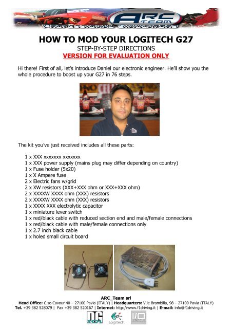
The kit you’ve just received includes all these parts:<br />
1 x XXX xxxxxxx xxxxxxx<br />
1 x XXX power supply (mains plug may differ depending on country)<br />
1 x Fuse holder (5x20)<br />
1 x X Ampere fuse<br />
2 x Electric fans w/grid<br />
2 x XW resistors (XXX+XXX ohm or XXX+XXX ohm)<br />
2 x XXXXW XXXX ohm (XXX) resistors<br />
2 x XXXXW XXXX ohm (XXX) resistors<br />
1 x XXXX XXX electrolytic capacitor<br />
1 x miniature lever switch<br />
1 x red/black cable with reduced section end and male/female connections<br />
1 x red/black cable with male/female connections only<br />
1 x 2.7 inch black cable<br />
1 x holed small circuit board<br />
<strong>ARC</strong>_<strong>Team</strong> srl<br />
Head Office: C.so Cavour 40 – 27100 Pavia (ITALY) | Headquarters: V.le Brambilla, 98 – 27100 Pavia (ITALY)<br />
Tel. +39 382 528079 | Fax +39 382 520167 | Internet: http://www.f1driving.it | E-mail: info@f1driving.it
Tools needed for getting the job done right:<br />
1. Soldering station with small tip (sharp pointed is preferred)<br />
2. Battery operated drill (with some bits)<br />
3. Battery operated screwdriver (you might use the drill for both)<br />
4. Hot glue gun<br />
5. Tin solder wire<br />
6. Pair of electrician’s scissors<br />
7. Regular mill bastard file<br />
8. Diagonal nippers<br />
9. Electronics pliers<br />
10. Phillips screwdriver<br />
11. Flat screwdriver<br />
12. Solder sucker<br />
13. Insulating tape<br />
<strong>ARC</strong>_<strong>Team</strong> srl<br />
Head Office: C.so Cavour 40 – 27100 Pavia (ITALY) | Headquarters: V.le Brambilla, 98 – 27100 Pavia (ITALY)<br />
Tel. +39 382 528079 | Fax +39 382 520167 | Internet: http://www.f1driving.it | E-mail: info@f1driving.it
Step #1<br />
Remove the six front wheel screws by<br />
a 4mm Allen key or the battery<br />
screwdriver (better and faster) with<br />
the appropriate bit.<br />
Step #2<br />
Remove the two screws on the gear<br />
switch board using the Phillips<br />
screwdriver.<br />
Take care to not pull off the wires which<br />
are connected to the wheel.<br />
Step #3<br />
Disconnect the board connector<br />
using the pliers or by hand.<br />
DON’T DISCONNECT PULLING<br />
THE WIRES!<br />
Now you can put aside the<br />
steering wheel.<br />
Let’s getting started!<br />
<strong>ARC</strong>_<strong>Team</strong> srl<br />
Head Office: C.so Cavour 40 – 27100 Pavia (ITALY) | Headquarters: V.le Brambilla, 98 – 27100 Pavia (ITALY)<br />
Tel. +39 382 528079 | Fax +39 382 520167 | Internet: http://www.f1driving.it | E-mail: info@f1driving.it
Step #4<br />
Remove the three screws which<br />
hold the gear shifter using the<br />
Phillips screwdriver or by the<br />
battery screwdriver (better and<br />
faster) with the appropriate Phillips<br />
bit.<br />
Step #5<br />
Just pull the gear shifter and remove it<br />
carefully taking care to not pull off the<br />
white connector.<br />
Step #6<br />
Turn the G27 upside down<br />
and remove the eight<br />
screws with the Phillips<br />
screwdriver, in picture are<br />
shown the screws position.<br />
<strong>ARC</strong>_<strong>Team</strong> srl<br />
Head Office: C.so Cavour 40 – 27100 Pavia (ITALY) | Headquarters: V.le Brambilla, 98 – 27100 Pavia (ITALY)<br />
Tel. +39 382 528079 | Fax +39 382 520167 | Internet: http://www.f1driving.it | E-mail: info@f1driving.it
Step #7<br />
Remove the top cover, then<br />
with a thin permanent<br />
marker draw on it the<br />
perimeters of the two square<br />
holes for the fans applying<br />
the sizes in picture.<br />
Step #8<br />
Pick up the battery drill and with a 13/64”<br />
(5mm) bit make a series of holes close to<br />
each other as much as you can all along the<br />
drawn perimeter keeping the holes inside<br />
the lines.<br />
Step #9<br />
At job done you should get a<br />
situation similar to this picture, now<br />
using the drill again with the same<br />
bit, break the links between the<br />
holes by tilting the drill back and<br />
forth in the holes.<br />
<strong>ARC</strong>_<strong>Team</strong> srl<br />
Head Office: C.so Cavour 40 – 27100 Pavia (ITALY) | Headquarters: V.le Brambilla, 98 – 27100 Pavia (ITALY)<br />
Tel. +39 382 528079 | Fax +39 382 520167 | Internet: http://www.f1driving.it | E-mail: info@f1driving.it
Step #10<br />
Now pick up the bastard file and<br />
make a filing job all around the<br />
square holes making them<br />
smooth and straight taking care<br />
to not go further the line bounds.<br />
Step #11<br />
Once having gotten the squares smooth<br />
try to insert the fans in.<br />
If you have correctly carried out the<br />
previous steps they won’t fit and that’s<br />
right, now use the file slightly till they fit<br />
in the holes as just they don’t fall<br />
through. The picture gives you an idea of<br />
how you should get the job.<br />
Step #12<br />
Remove the fans and turn the cover on<br />
its inner side, using the battery drill with<br />
a 17/64” (6.5mm) bit (up to 23/64”<br />
recommended) make a hole in the<br />
position shown in picture.<br />
<strong>ARC</strong>_<strong>Team</strong> srl<br />
Head Office: C.so Cavour 40 – 27100 Pavia (ITALY) | Headquarters: V.le Brambilla, 98 – 27100 Pavia (ITALY)<br />
Tel. +39 382 528079 | Fax +39 382 520167 | Internet: http://www.f1driving.it | E-mail: info@f1driving.it
Step #13<br />
Now enlarge the hole with<br />
a 33/64” (13mm) bit using<br />
the battery drill VERY<br />
SLOWLY or turn it by hand.<br />
This is the hole for the fuse<br />
holder.<br />
Step #14<br />
Using the battery<br />
drill with a 17/64”<br />
(6.5mm) bit make<br />
a hole in the<br />
position shown in<br />
picture.<br />
This is the hole for<br />
the lever switch.<br />
Step #15<br />
Remove the two screws shown in<br />
picture with the Phillips<br />
screwdriver.<br />
<strong>ARC</strong>_<strong>Team</strong> srl<br />
Head Office: C.so Cavour 40 – 27100 Pavia (ITALY) | Headquarters: V.le Brambilla, 98 – 27100 Pavia (ITALY)<br />
Tel. +39 382 528079 | Fax +39 382 520167 | Internet: http://www.f1driving.it | E-mail: info@f1driving.it
Step #16<br />
The two plastic “fins” (pointed<br />
by the arrows) must be<br />
removed.<br />
That’s an important device, it<br />
ensures the correct air flow<br />
while the two fans are working.<br />
Step #17<br />
Pick up the electrician’s<br />
scissors and cut the<br />
both ends of the fins.<br />
Step #18<br />
Pick up the nippers and cut a triangle shape on the fin<br />
side support as shown in pictures, the first cut at the<br />
base of the fin, the second just over the first one with<br />
the nippers rotated by 180° (shown in second<br />
picture).<br />
<strong>ARC</strong>_<strong>Team</strong> srl<br />
Head Office: C.so Cavour 40 – 27100 Pavia (ITALY) | Headquarters: V.le Brambilla, 98 – 27100 Pavia (ITALY)<br />
Tel. +39 382 528079 | Fax +39 382 520167 | Internet: http://www.f1driving.it | E-mail: info@f1driving.it
Step #19<br />
Make the same<br />
operation on the other<br />
support and the other<br />
fin.<br />
Step #20<br />
Now remove the fins by<br />
bending back and forth till<br />
they come off.<br />
Step #21<br />
Reassemble the front grid with its screws<br />
and now you can see that openings have<br />
turned in a real functioning air vents.<br />
Cool, eh?<br />
<strong>ARC</strong>_<strong>Team</strong> srl<br />
Head Office: C.so Cavour 40 – 27100 Pavia (ITALY) | Headquarters: V.le Brambilla, 98 – 27100 Pavia (ITALY)<br />
Tel. +39 382 528079 | Fax +39 382 520167 | Internet: http://www.f1driving.it | E-mail: info@f1driving.it
Step #22<br />
Pick up the fuse holder + nut,<br />
put it in its hole and tight it up<br />
using a 14mm spanner or<br />
pliers.<br />
DON’T TIGHT THE NUT TOO<br />
MUCH, THERE’S THE RISK TO<br />
GET IT BROKEN!<br />
Step #23<br />
Pick up the lever switch, unscrew the top nut and<br />
remove the teeth lock washer, leave on the plain<br />
washer and the bottom nut (1 st picture), put the<br />
switch in its hole and hold it by fingers correctly<br />
oriented (2 nd picture).<br />
<strong>ARC</strong>_<strong>Team</strong> srl<br />
Head Office: C.so Cavour 40 – 27100 Pavia (ITALY) | Headquarters: V.le Brambilla, 98 – 27100 Pavia (ITALY)<br />
Tel. +39 382 528079 | Fax +39 382 520167 | Internet: http://www.f1driving.it | E-mail: info@f1driving.it
Step #24<br />
Put the teeth lock washer on and then the nut,<br />
tight it up using an 8mm spanner.<br />
Step #25<br />
Pick up the fuse and the fuse socket, put them<br />
together then insert in the fuse holder.<br />
Step #26<br />
Lock the fuse socket screwing it up with the flat screwdriver.<br />
After this step the job gets more complex and requires more<br />
and more accuracy.<br />
Let’s go ahead!<br />
<strong>ARC</strong>_<strong>Team</strong> srl<br />
Head Office: C.so Cavour 40 – 27100 Pavia (ITALY) | Headquarters: V.le Brambilla, 98 – 27100 Pavia (ITALY)<br />
Tel. +39 382 528079 | Fax +39 382 520167 | Internet: http://www.f1driving.it | E-mail: info@f1driving.it
Step #27<br />
Now let’s focus on the electronic section.<br />
Disconnect all the connectors on the main<br />
board using the pliers or by hand.<br />
DON’T DISCONNECT PULLING THE WIRES!<br />
Step #28<br />
Remove the four screws (red spots in picture) by<br />
the Phillips screwdriver.<br />
Step #29<br />
Picture and text available after<br />
having purchased the kit.<br />
<strong>ARC</strong>_<strong>Team</strong> srl<br />
Head Office: C.so Cavour 40 – 27100 Pavia (ITALY) | Headquarters: V.le Brambilla, 98 – 27100 Pavia (ITALY)<br />
Tel. +39 382 528079 | Fax +39 382 520167 | Internet: http://www.f1driving.it | E-mail: info@f1driving.it
Step #30<br />
Picture and text available after<br />
having purchased the kit.<br />
Step #31<br />
Picture and text available after having<br />
purchased the kit.<br />
Step #32<br />
Picture and text available after having<br />
purchased the kit.<br />
<strong>ARC</strong>_<strong>Team</strong> srl<br />
Head Office: C.so Cavour 40 – 27100 Pavia (ITALY) | Headquarters: V.le Brambilla, 98 – 27100 Pavia (ITALY)<br />
Tel. +39 382 528079 | Fax +39 382 520167 | Internet: http://www.f1driving.it | E-mail: info@f1driving.it
Step #33<br />
Pictures and text available after having<br />
purchased the kit.<br />
Step #34<br />
Picture and text available after having<br />
purchased the kit.<br />
<strong>ARC</strong>_<strong>Team</strong> srl<br />
Head Office: C.so Cavour 40 – 27100 Pavia (ITALY) | Headquarters: V.le Brambilla, 98 – 27100 Pavia (ITALY)<br />
Tel. +39 382 528079 | Fax +39 382 520167 | Internet: http://www.f1driving.it | E-mail: info@f1driving.it
Step #35<br />
Picture and text available after<br />
having purchased the kit.<br />
Step #36<br />
Picture and text available after<br />
having purchased the kit.<br />
Step #37<br />
Picture and text available after<br />
having purchased the kit.<br />
<strong>ARC</strong>_<strong>Team</strong> srl<br />
Head Office: C.so Cavour 40 – 27100 Pavia (ITALY) | Headquarters: V.le Brambilla, 98 – 27100 Pavia (ITALY)<br />
Tel. +39 382 528079 | Fax +39 382 520167 | Internet: http://www.f1driving.it | E-mail: info@f1driving.it
Step #38<br />
Pick up the cable shown<br />
in picture (reduced<br />
section on one end).<br />
Step #39<br />
Pictures and text available after having<br />
purchased the kit.<br />
Step #40<br />
Picture and text available after having<br />
purchased the kit.<br />
<strong>ARC</strong>_<strong>Team</strong> srl<br />
Head Office: C.so Cavour 40 – 27100 Pavia (ITALY) | Headquarters: V.le Brambilla, 98 – 27100 Pavia (ITALY)<br />
Tel. +39 382 528079 | Fax +39 382 520167 | Internet: http://www.f1driving.it | E-mail: info@f1driving.it
Step #41<br />
Picture and text available after having<br />
purchased the kit.<br />
Step #42<br />
Picture and text available after having purchased the<br />
kit.<br />
Step #43<br />
Picture and text available after<br />
having purchased the kit.<br />
<strong>ARC</strong>_<strong>Team</strong> srl<br />
Head Office: C.so Cavour 40 – 27100 Pavia (ITALY) | Headquarters: V.le Brambilla, 98 – 27100 Pavia (ITALY)<br />
Tel. +39 382 528079 | Fax +39 382 520167 | Internet: http://www.f1driving.it | E-mail: info@f1driving.it
Step #44<br />
Pictures and text available after having<br />
purchased the kit.<br />
Step #45<br />
Now pick up the housing cover, it’s time to<br />
fix the fans appropriately.<br />
Mount it back on the wheel base as shown<br />
(no need to screw it up), this procedure is<br />
for placing correctly the fans in depth of the<br />
holes as just enough to not touch the motors<br />
and the upper corners of the electronic<br />
board once mounted back.<br />
Step #46<br />
Insert the fans in the holes<br />
keeping the wires side facing the<br />
front of the cover (hub hole).<br />
THE FAN WITH THE INSERT<br />
CONNECTOR ON THE BLACK WIRE<br />
MUST BE MOUNTED ON THE<br />
SWITCH/FUSE SIDE.<br />
The correct depth of the fans<br />
should be about as shown, try to<br />
find it out by looking through the air vents you opened in the past steps (cool, eh?).<br />
<strong>ARC</strong>_<strong>Team</strong> srl<br />
Head Office: C.so Cavour 40 – 27100 Pavia (ITALY) | Headquarters: V.le Brambilla, 98 – 27100 Pavia (ITALY)<br />
Tel. +39 382 528079 | Fax +39 382 520167 | Internet: http://www.f1driving.it | E-mail: info@f1driving.it
Step #47<br />
Remove the cover from the<br />
base, holding the fans in<br />
position by hand get them<br />
blocked using the hot glue<br />
gun all around their<br />
perimeter.<br />
Step #48<br />
Once the glue has cooled down<br />
enough get started to make<br />
electric connections.<br />
Cut the wires at a convenient<br />
size and solder the black wire of<br />
the left fan together with the red<br />
one of the right fan (connection<br />
in series) as shown in picture,<br />
then fix down the wire with a<br />
drop of hot glue.<br />
<strong>ARC</strong>_<strong>Team</strong> srl<br />
Head Office: C.so Cavour 40 – 27100 Pavia (ITALY) | Headquarters: V.le Brambilla, 98 – 27100 Pavia (ITALY)<br />
Tel. +39 382 528079 | Fax +39 382 520167 | Internet: http://www.f1driving.it | E-mail: info@f1driving.it
Step #49<br />
Pick up the two XX resistors,<br />
they might be XXX + XXX ohm<br />
or XXX + XXX ohm.<br />
Pictures and full text available<br />
after having purchased the kit.<br />
Step #50<br />
Cut the red wire of the left fan long enough to<br />
get<br />
Picture and full text available after having<br />
purchased the kit.<br />
Step #51<br />
Solder the red wire<br />
previously cut to the other<br />
end<br />
Picture and full text<br />
available after having<br />
purchased the kit.<br />
<strong>ARC</strong>_<strong>Team</strong> srl<br />
Head Office: C.so Cavour 40 – 27100 Pavia (ITALY) | Headquarters: V.le Brambilla, 98 – 27100 Pavia (ITALY)<br />
Tel. +39 382 528079 | Fax +39 382 520167 | Internet: http://www.f1driving.it | E-mail: info@f1driving.it
Step #52<br />
Fix down the red fans wires with a drop of<br />
hot glue approximately in the spots shown<br />
in the pictures highlighted by red arrow.<br />
Picture and full text available after having<br />
purchased the kit.<br />
Step #53<br />
Cut and put two stripes of<br />
insulating tape close to the<br />
Picture and full text available after<br />
having purchased the kit.<br />
Step #54<br />
Pick up the 2.7 inch black<br />
wire.<br />
<strong>ARC</strong>_<strong>Team</strong> srl<br />
Head Office: C.so Cavour 40 – 27100 Pavia (ITALY) | Headquarters: V.le Brambilla, 98 – 27100 Pavia (ITALY)<br />
Tel. +39 382 528079 | Fax +39 382 520167 | Internet: http://www.f1driving.it | E-mail: info@f1driving.it
Step #55<br />
Solder the black wire as shown in<br />
picture, one end to the side<br />
contact of the fuse holder and the<br />
other end to the side contact of<br />
the switch.<br />
Get it well shaped bending it on<br />
the base.<br />
Step #56<br />
Pick up the cable<br />
shown in picture<br />
(red/black with<br />
male and female<br />
connectors).<br />
Step #57<br />
Solder the male<br />
connector wire to the<br />
bottom contact of the<br />
fuse holder.<br />
<strong>ARC</strong>_<strong>Team</strong> srl<br />
Head Office: C.so Cavour 40 – 27100 Pavia (ITALY) | Headquarters: V.le Brambilla, 98 – 27100 Pavia (ITALY)<br />
Tel. +39 382 528079 | Fax +39 382 520167 | Internet: http://www.f1driving.it | E-mail: info@f1driving.it
Step #58<br />
Solder the female connector<br />
wire to the centre pin of the<br />
switch together with the red<br />
wire of the fans (as shown in<br />
picture).<br />
Step #59<br />
Reassemble the main board in place<br />
screwing it up and reconnect all the<br />
connectors<br />
Full picture and text available after<br />
having purchased the kit.<br />
Step #60<br />
Pick up this thin black wire disconnecting it<br />
from the fan (the one beside the fuse/switch).<br />
<strong>ARC</strong>_<strong>Team</strong> srl<br />
Head Office: C.so Cavour 40 – 27100 Pavia (ITALY) | Headquarters: V.le Brambilla, 98 – 27100 Pavia (ITALY)<br />
Tel. +39 382 528079 | Fax +39 382 520167 | Internet: http://www.f1driving.it | E-mail: info@f1driving.it
Step #61<br />
Solder it together with the black wire of<br />
Picture and full text available after having<br />
purchased the kit.<br />
Step #62<br />
Locate the supply socket on the wheel base<br />
and especially its black wire, it’s placed in the<br />
low left corner.<br />
Step #63<br />
Solder the two black wires together with the<br />
black wire on the supply socket.<br />
The original wire won’t come off while<br />
soldering because the copper is folded in the<br />
pin hole.<br />
<strong>ARC</strong>_<strong>Team</strong> srl<br />
Head Office: C.so Cavour 40 – 27100 Pavia (ITALY) | Headquarters: V.le Brambilla, 98 – 27100 Pavia (ITALY)<br />
Tel. +39 382 528079 | Fax +39 382 520167 | Internet: http://www.f1driving.it | E-mail: info@f1driving.it
Step #64<br />
Pick up the nippers and cut the screw side<br />
support as shown in the red circle.<br />
You need<br />
Picture and full text available after having<br />
purchased the kit.<br />
Step #65<br />
Full text available after having purchased<br />
the kit.<br />
Step #66<br />
Picture and text available after having purchased<br />
the kit.<br />
<strong>ARC</strong>_<strong>Team</strong> srl<br />
Head Office: C.so Cavour 40 – 27100 Pavia (ITALY) | Headquarters: V.le Brambilla, 98 – 27100 Pavia (ITALY)<br />
Tel. +39 382 528079 | Fax +39 382 520167 | Internet: http://www.f1driving.it | E-mail: info@f1driving.it
Step #67<br />
Full picture and text available after having<br />
purchased the kit.<br />
Step #68<br />
Lean the wheel base on the table with<br />
the hub facing down.<br />
Pick up the housing cover and<br />
reconnect the insert connector of the<br />
black fan wire.<br />
Step #69<br />
Connect the insert male<br />
connector from the main<br />
board to the female one<br />
on the cover.<br />
<strong>ARC</strong>_<strong>Team</strong> srl<br />
Head Office: C.so Cavour 40 – 27100 Pavia (ITALY) | Headquarters: V.le Brambilla, 98 – 27100 Pavia (ITALY)<br />
Tel. +39 382 528079 | Fax +39 382 520167 | Internet: http://www.f1driving.it | E-mail: info@f1driving.it
Step #70<br />
Make the same on the<br />
other connector, the<br />
female from the main<br />
board to the male on the<br />
cover.<br />
Step #71<br />
Now carefully close the housing taking care of every wire,<br />
arrange well keeping them beside the motor.<br />
Full picture available after having purchased the kit.<br />
Step #72<br />
If each cable and wire is well set the housing cover<br />
gets closed by itself with no force applied.<br />
Now turn the G27 upside down and lock all the eight<br />
screws back in place.<br />
<strong>ARC</strong>_<strong>Team</strong> srl<br />
Head Office: C.so Cavour 40 – 27100 Pavia (ITALY) | Headquarters: V.le Brambilla, 98 – 27100 Pavia (ITALY)<br />
Tel. +39 382 528079 | Fax +39 382 520167 | Internet: http://www.f1driving.it | E-mail: info@f1driving.it
Step #73<br />
Lock the gear-shifter with the Phillips<br />
screwdriver or the battery screwdriver<br />
with Phillips bit (better).<br />
Step #74<br />
Reconnect the gear switch<br />
board connector and lock it back<br />
in place with the two screws<br />
using the Phillips screwdriver.<br />
<strong>ARC</strong>_<strong>Team</strong> srl<br />
Head Office: C.so Cavour 40 – 27100 Pavia (ITALY) | Headquarters: V.le Brambilla, 98 – 27100 Pavia (ITALY)<br />
Tel. +39 382 528079 | Fax +39 382 520167 | Internet: http://www.f1driving.it | E-mail: info@f1driving.it
Step #75<br />
Lock the steering wheel with its<br />
screws using a 4mm Allen key or the<br />
battery screwdriver (better and faster)<br />
with the appropriate bit.<br />
Step #76<br />
Now connect the plug of the<br />
new power supply to the<br />
steering wheel in the same<br />
way you would do before<br />
with the old one, arrange the<br />
cable in the groove (it’s just<br />
a bit bigger but it does fit)<br />
then the other plug in the<br />
mains socket and last the<br />
usb connector to <strong>your</strong> PC.<br />
YOU GOT IT!<br />
ENJOY YOUR NEW G27-E BY <strong>ARC</strong>_TEAM<br />
<strong>ARC</strong>_<strong>Team</strong> srl<br />
Head Office: C.so Cavour 40 – 27100 Pavia (ITALY) | Headquarters: V.le Brambilla, 98 – 27100 Pavia (ITALY)<br />
Tel. +39 382 528079 | Fax +39 382 520167 | Internet: http://www.f1driving.it | E-mail: info@f1driving.it