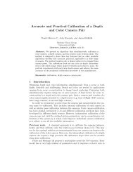
Accurate, Dense, and Robust Multiview Stereopsis - Department of ...
Accurate, Dense, and Robust Multiview Stereopsis - Department of ...
Accurate, Dense, and Robust Multiview Stereopsis - Department of ...

Create successful ePaper yourself
Turn your PDF publications into a flip-book with our unique Google optimized e-Paper software.
1366 IEEE TRANSACTIONS ON PATTERN ANALYSIS AND MACHINE INTELLIGENCE, VOL. 32, NO. 8, AUGUST 2010<br />
Fig. 5. (a) Given an existing patch, an expansion procedure is performed<br />
to generate new ones for the neighboring empty image cells in its visible<br />
images. The expansion procedure is not performed for an image cell<br />
(b) if there already exists a neighboring patch reconstructed there or<br />
(c) if there is a depth discontinuity when viewed from the camera. See<br />
text for more details.<br />
becomes a reference <strong>and</strong> the patch optimization fails.<br />
However, this does not prevent the procedure starting<br />
from another image without artifacts, which will succeed. 6<br />
3.2 Expansion<br />
The goal <strong>of</strong> the expansion step is to reconstruct at least one<br />
patch in every image cell Ciðx; yÞ, <strong>and</strong> we repeat taking<br />
existing patches <strong>and</strong> generating new ones in nearby empty<br />
spaces. More concretely, given a patch p, we first identify a<br />
set <strong>of</strong> neighboring image cells CðpÞ satisfying certain criteria,<br />
then perform a patch expansion procedure for each one <strong>of</strong><br />
these, as detailed in the following sections.<br />
3.2.1 Identifying Cells for Expansion<br />
Given a patch p, we initialize CðpÞ by collecting the<br />
neighboring image cells in its each visible image:<br />
CðpÞ ¼fCiðx 0 ;y 0 Þjp 2 Qiðx; yÞ; jx x 0 jþjy y 0 j¼1g:<br />
First, the expansion is unnecessary if a patch has already<br />
been reconstructed there. Concretely, if an image cell<br />
Ciðx 0 ;y 0 Þ2CðpÞ contains a patch p 0 , which is a neighbor <strong>of</strong><br />
p, Ciðx 0 ;y 0 Þ is removed from the set CðpÞ, where a pair <strong>of</strong><br />
patches p <strong>and</strong> p 0 are defined to be neighbors if<br />
jðcðpÞ cðp 0 ÞÞ nðpÞj þ jðcðpÞ cðp 0 ÞÞ nðp 0 Þj < 2 1: ð8Þ<br />
1 is the distance corresponding to an image displacement<br />
<strong>of</strong> 1 pixels in the reference image RðpÞ at the depth <strong>of</strong> the<br />
centers <strong>of</strong> cðpÞ <strong>and</strong> cðp 0 Þ. Second, even when no patch has<br />
been reconstructed, the expansion procedure is unnecessary<br />
for an image cell if there is a depth discontinuity viewed<br />
from the corresponding camera (see an example in Fig. 5). 7<br />
Since it is, in practice, difficult to judge the presence <strong>of</strong><br />
depth discontinuities before actually reconstructing a surface,<br />
we simply judge that the expansion is unnecessary due<br />
to a depth discontinuity if Q i ðx 0 ;y 0 Þ is not empty: If Ciðx 0 ;y 0 Þ<br />
already contains a patch whose photometric discrepancy<br />
score associated with Ii is better than the threshold<br />
defined in (2).<br />
6. Of course, this relatively simple procedure may not be perfect <strong>and</strong><br />
may yield mistakes, but we also have a filtering step described in Section 3.3<br />
to h<strong>and</strong>le such errors.<br />
7. This second selection criteria is for computational efficiency, <strong>and</strong> can<br />
be removed for simplicity because the filtering step can remove erroneous<br />
patches possibly caused by bad expansion procedure.<br />
Fig. 6. Patch expansion algorithm. The expansion <strong>and</strong> the filtering<br />
procedure is iterated n ð¼ 3Þ times to make patches dense <strong>and</strong> remove<br />
outliers.<br />
3.2.2 Expansion Procedure<br />
For each collected image cell Ciðx; yÞ in CðpÞ, the following<br />
expansion procedure is performed to generate a new patch p 0 :<br />
We first initialize nðp 0 Þ, Rðp 0 Þ, <strong>and</strong> V ðp 0 Þ by the corresponding<br />
values <strong>of</strong> p. cðp 0 Þ is, in turn, initialized as the point<br />
where the viewing ray passing through the center <strong>of</strong> Ciðx; yÞ<br />
intersects the plane containing the patch p. After computing<br />
V ðp 0 Þ from V ðpÞ by using (2), we refine cðp 0 Þ <strong>and</strong> nðp 0 Þ by<br />
the optimization procedure described in Section 2.3. During<br />
the optimization, cðp 0 Þ is constrained to lie on a ray such<br />
that its image projection in Ii does not change in order to<br />
make sure that the patch always projects inside the image<br />
cell Ciðx; yÞ. After the optimization, we add to V ðp 0 Þ a set <strong>of</strong><br />
images in which the patch should be visible according to a<br />
depth-map test, where a depth value is computed for each<br />
image cell instead <strong>of</strong> a pixel, then update V ðp 0 Þ according<br />
to (2). It is important to add visible images obtained from<br />
the depth-map test to V ðp 0 Þ instead <strong>of</strong> replacing the whole<br />
set, because some matches (<strong>and</strong> thus the corresponding<br />
depth map information) may be incorrect at this point. Due<br />
to this update rule, the visibility information associated<br />
with reconstructed patches becomes inconsistent with each<br />
other, a fact that is used in the following filtering step to<br />
reject erroneous patches. Finally, if jV ðp 0 Þj , we accept<br />
the patch as a success <strong>and</strong> update Qiðx; yÞ <strong>and</strong> Q i ðx; yÞ for<br />
its visible images. Note that, as in the initial feature<br />
matching step, is set to 0.6 <strong>and</strong> 0.3, before <strong>and</strong> after the<br />
optimization, respectively, but we loosen (increase) both<br />
values by 0.2 after each expansion/filtering iteration in<br />
order to h<strong>and</strong>le challenging (homogeneous or relatively<br />
texture-less) regions in the latter iterations. The overall<br />
algorithm description is given in Fig. 6. Note that when<br />
segmentation information is available, we simply ignore<br />
image cells in the background during initial feature<br />
matching <strong>and</strong> the expansion procedure, which guarantees<br />
that no patches are reconstructed in the background. The<br />
bounding volume information is not used to filter out<br />
erroneous patches in our experiments, although it would<br />
not be difficult to do so.