Lesson 1-4: Structured Cabling Systems
Lesson 1-4: Structured Cabling Systems
Lesson 1-4: Structured Cabling Systems

You also want an ePaper? Increase the reach of your titles
YUMPU automatically turns print PDFs into web optimized ePapers that Google loves.
Unit 1: Internetworking Overview<br />
<strong>Lesson</strong> 1-4: <strong>Structured</strong> <strong>Cabling</strong> <strong>Systems</strong><br />
At a Glance<br />
What You Will Learn<br />
This lesson describes both physical and logical organization of networks.<br />
Topologies described include bus, ring, star, and hybrid. This unit also<br />
covers TIA/EIA 568 structured cabling standards, which govern the<br />
installation of local area networks. In order to design, install,<br />
troubleshoot, and maintain networks, administrators must have a solid<br />
understanding of these topologies and cabling standards.<br />
After completing this lesson, you will be able to:<br />
• Identify and describe the elements that are recommended for<br />
structured cabling networks.<br />
• Diagram bus, star, ring, and hybrid topologies.<br />
• Compare and contrast the advantages and disadvantages of bus, star,<br />
ring, and hybrid topologies.<br />
• Select the appropriate topology for a particular set of network<br />
requirements.<br />
• Create a questionnaire for an administrator to use when planning or<br />
expanding a network.<br />
• Select and estimate the cost of cabling for a given network.<br />
ST0025803A<br />
89
Tech Talk<br />
90<br />
<strong>Lesson</strong> 1-4: <strong>Structured</strong> <strong>Cabling</strong> <strong>Systems</strong><br />
• Active Hub⎯Type of hub that monitors, amplifies, and regenerates<br />
signals. Signals are strengthened in active hubs. The opposite of a<br />
passive hub.<br />
• Attenuation⎯The weakening of a signal as it travels over connection<br />
media; also referred to as signal degradation.<br />
• Bus Topology⎯Network topology where computer devices are<br />
connected in a row to a continuous length of cable segment. Each end<br />
of the cable segment must be terminated by means of a terminating<br />
resistor.<br />
• Logical Topology⎯Logical topology describes the actual path of data<br />
signals through a network. It does not refer to the physical layout of<br />
the network.<br />
• Passive Hub⎯Type of hub that does not take an active role in<br />
maintaining, processing, or regenerating signals. A passive hub serves<br />
only as a physical connection point for computer devices. The opposite<br />
of active hub.<br />
• Patch Panel⎯ Connection point located in a secure closet and used to<br />
terminate the horizontal and vertical cables.<br />
• Physical Topology⎯The attributes and physical setup, not logical<br />
topology, of a network. Physical topology describes the physical<br />
connections and arrangement of the internetworking devices.<br />
• Redundancy⎯Networking redundancy refers to the additional<br />
equipment or measures taken to ensure continuous operation of a<br />
network. One example is having an extra server available in case one<br />
goes down.<br />
• Ring Topology⎯Closed network with no beginning or end point.<br />
Computer devices are all connected to one main cable segment in a<br />
continuous fashion. Termination devices are not necessary. All<br />
computers have equal access to the network.<br />
• Star Topology⎯Topology that uses point-to-point wiring. There is a<br />
central hub, which receives and transmits signals over the network.<br />
Each computer device is connected to a hub, not directly to the other<br />
computers.<br />
• Terminator⎯Device connected at the end of each wire segment in bus<br />
networks. Terminators absorb transmission signals, which prevent<br />
them from bouncing back and causing interference.<br />
ST0025803A Internetworking Fundamentals
Unit 1: Internetworking Overview<br />
Elements of <strong>Structured</strong> <strong>Cabling</strong> <strong>Systems</strong><br />
When computer networks were first designed, future expansion and/or<br />
upgrading needs were not anticipated. Original networks were small,<br />
often as few as two or three computers and a printer connected together in<br />
the same office. Existing equipment was cabled together in a somewhat<br />
haphazard manner and networks that went beyond single-site locations<br />
were neither envisioned nor planned for. There was no need for cabling<br />
and networking standards.<br />
As networks grew, and became common, it became apparent to vendors<br />
that standards needed to be implemented to provide interoperability.<br />
Initial structured cabling standards were vendor specific, for example,<br />
Token Ring networks by IBM and Ethernet networks by Digital<br />
Equipment Corporation. These standards were adequate at that time<br />
since networks still did not extend beyond single-site office locations and it<br />
was common to have equipment from only one vendor.<br />
As networks expanded to include several offices and buildings,<br />
corporations became more dependent upon networking to conduct everyday<br />
business transactions. This created interoperability issues; one location<br />
may have IBM equipment, another Compaq, and so on. The inability to<br />
network with other locations became an economic issue. Also, vendor<br />
specific standards made worldwide internetworking nearly impossible.<br />
The need for permanent, interoperable, industry-wide structured cabling<br />
standards become necessary for a global economy.<br />
In the early 90s, the Telecommunications Industry Association/Electronic<br />
Industries Association (TIA/EIA) developed industry-wide,<br />
internetworking, structured cabling standards. The TIA/EIA 568-<br />
standard, which you learned about in the <strong>Cabling</strong> lesson, attempts to make<br />
the installation of computer networks as efficient and consistent as the<br />
installation of telephone systems. The 568 standard breaks down the<br />
installation of wiring within a building into manageable pieces and governs<br />
wiring specifications for 10BASE-T, 100BASE-TX, 100BASE-T4, 100VG-<br />
AnyLAN, LocalTalk, Token Ring 4 and 16 Mb/s, and FDDI.<br />
When designing or expanding networks, system administrators use current<br />
TIA/EIA 568 cabling specifications as a guide. This helps ensure both<br />
backward and forward compatibility for networks. Backward/forward<br />
compatibility means that new equipment functions with already existing<br />
networking devices and also takes into account future expansion<br />
requirements.<br />
ST0025803A<br />
91
92<br />
<strong>Lesson</strong> 1-4: <strong>Structured</strong> <strong>Cabling</strong> <strong>Systems</strong><br />
<strong>Structured</strong> cabling specification 568 makes recommendations for the<br />
following basic elements of networks:<br />
• Building Entrance Requirements⎯Specifications for the point at<br />
which outside cabling enters a building.<br />
• Equipment Room⎯Storage area for the more expensive, complex<br />
equipment, often the existing telecommunications closets.<br />
• Backbone <strong>Cabling</strong>⎯<strong>Cabling</strong> (often referred to as vertical) that<br />
carries the signals from equipment room to equipment room, between<br />
floors, and to and from the building entrance connections.<br />
• Horizontal <strong>Cabling</strong>⎯Transmission media that carries signals from a<br />
same floor equipment room to the various work areas.<br />
• Work Area⎯Any area where the computer workstations, printers, etc.<br />
are located, typically office space.<br />
Building Entrance Requirements<br />
The building entrance requirements are simply the specifications for the<br />
point at which the cabling enters a building. The specifications include<br />
recommendations for the type of connecting and surge protection devices.<br />
The standard also specifies the placement of the cabling used to connect<br />
the inside wiring to other buildings.<br />
Equipment Room<br />
The equipment room is typically the existing telecommunications closet. It<br />
can be any secure storage area where the communications racks, cables,<br />
and other more expensive hardware devices, such as patch panels, hubs,<br />
switches, and routers are located.<br />
A locked equipment room helps prevent the theft of equipment and data<br />
security and also helps prevent accidental damage from untrained<br />
individuals.<br />
The TIA/EIA 568 standards recommend that the equipment room be<br />
located in the middle of the office space, if possible. In this way, the cables<br />
that run from the equipment room to the work areas can be approximately<br />
the same lengths, and at the same time adhere to the maximum length<br />
standards. This helps ensure reliable transmission of data.<br />
ST0025803A Internetworking Fundamentals
Unit 1: Internetworking Overview<br />
Backbone <strong>Cabling</strong><br />
Backbone cabling is the wiring that runs vertically between floors and/or<br />
between equipment rooms. Backbone cabling provides the<br />
interconnections between equipment rooms and the building entrance site,<br />
including cross-connects, patch cords, and terminators. Backbone cabling<br />
can also extend between buildings.<br />
When planning a network it is a good idea to double or even triple the<br />
length of backbone cable that is needed for installation. This provides for<br />
expansion and the ability to run redundant connections.<br />
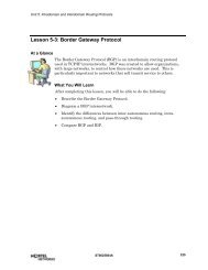
Backbone <strong>Cabling</strong> Connects Equipment Rooms<br />
ST0025803A<br />
Backbone<br />
Cable<br />
Backbon<br />
eCable Cable Type<br />
Limit Depends on<br />
Patch Cable<br />
6 Meter Limit<br />
The wiring used for backbone cabling may be either copper or fiber optic.<br />
Recommended backbone cable maximum distance limitations include:<br />
• Voice grade 100 ohm UTP 800 meter limitation<br />
• STP data grade 150 ohm 90 meter limitation<br />
• Multimode 62.5/125µm fiber 2,000 meter limitation<br />
• Patch cable 3 - 6 meter limitation<br />
93
94<br />
<strong>Lesson</strong> 1-4: <strong>Structured</strong> <strong>Cabling</strong> <strong>Systems</strong><br />
When using copper wire for backbone cabling, avoid sources of high level<br />
electromagnetic or radio frequency interference (EMI/RFI). Fiber optic<br />
cable, although more expensive, has distinct advantages over copper since<br />
it can be run in locations such as elevator shafts or alongside power lines<br />
with no EMI/RFI affects. Since backbone cabling is stationary and there is<br />
less of it used, spending more money per unit length for high-speed<br />
backbone fiber optic cable is often the best choice. Recently, the price of<br />
fiber optic cable was reduced making this the current backbone cable of<br />
choice.<br />
Horizontal <strong>Cabling</strong><br />
Horizontal cable is the physical media that runs from the wall jack at the<br />
workstation outlet to the termination in the equipment room. It also<br />
includes the cable run from the wall outlet to the workstation, and the<br />
cable in equipment closets that connects hubs, switches, and so on. These<br />
short pieces of cable are called patch cords or patch cable. There is a 3meter<br />
limit from the wall jack to the workstation and a 6-meter limit<br />
between equipment in the telecommunications closet.<br />
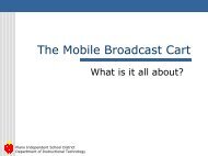
Horizontal <strong>Cabling</strong><br />
Horizontal<br />
Horizonta<br />
Cable<br />
lCable<br />
90 Meter Limit<br />
Patch Cable<br />
3 Meter Limit<br />
Patch<br />
Cables<br />
Most often, horizontal cable is routed directly from the wiring closet to the<br />
workstation, without splices, cable junctures, or taps. By eliminating<br />
splices, cable junctures and/or taps, the potential for faulty connections<br />
and electrical noise is reduced. Although not necessary, it is recommended<br />
that horizontal cabling be rated for category 5 use.<br />
ST0025803A Internetworking Fundamentals
Unit 1: Internetworking Overview<br />
Maximum transmission speeds for horizontal cable are:<br />
• Category 3 up to 16 MHz<br />
• Category 4 up to 20 MHz<br />
• Category 5 up to 100 MHz<br />
Maximum recommended distance limitation for horizontal cable:<br />
• 100 meters total<br />
• Maximum of 3 meters from wall jack to workstation<br />
• Maximum of 6 meters in the telecommunications closet<br />
• Maximum of 90 meters from telecommunications closet to wall jack<br />
Cable lengths from the computer workstation running to the hub in the<br />
equipment room may not exceed 100 meters, including the patch cable.<br />
The distance from the closet to the workstation should not exceed 90<br />
meters. This leaves only 10 meters. It is strongly recommended that less<br />
than 3 meters be used for workstation-to-wall-outlet patch cable and less<br />
than 6 meters for patch cable in the wiring closet. The wall jack outlet<br />
must have a minimum of two ports, one for voice grade transmissions and<br />
one for data grade transmissions. Recommended horizontal cabling<br />
includes:<br />
• 4-pair 100 ohm UTP<br />
• 2-pair 150 ohm STP<br />
• 2 fiber 62.5/125µm optical<br />
When installing horizontal cable, it is important to avoid any sources of<br />
electromagnetic interference (EMI), such as elevator motors, portable<br />
heaters, electrical wiring, air conditioning, metal beams, and walls.<br />
Horizontal cable may be run under carpets, along ceiling tiles, over beams<br />
or frames, through wiring trays, through firewalls, or even as conduit back<br />
to the wiring closet. Cable lengths should be tested after installation and<br />
before equipment is attached.<br />
Fiber optic cable is not subject to the same distance limitations, nor is it<br />
subject to EMI/RFI, however it is fragile and expensive and should only be<br />
installed by qualified technicians.<br />
ST0025803A<br />
95
96<br />
Work Area<br />
<strong>Lesson</strong> 1-4: <strong>Structured</strong> <strong>Cabling</strong> <strong>Systems</strong><br />
The work area components include the computers, telephones, patch<br />
cables, adapters, and so on. Workstations are connected to the wall outlet<br />
by patch cables.<br />
It is recommended that one wall jack be for category 5 wiring, and a second<br />
jack for UTP category 5, STP cable, or fiber optic cable. A network planned<br />
for future expansion often has six outlets. It is specified that category 5<br />
cable be terminated with an 8-pin, RJ-45 wall jack; STP to a 4-position<br />
shielded token ring connector, and, fiber optic to a SCFOC/2.5 duplex<br />
connector. We will discuss these connectors later in the course.<br />
Check Your Understanding<br />
♦ Why are industry-wide, interoperable internetworking standards<br />
for cables important?<br />
♦ List the elements of the TIA/EIA 568 structured cabling<br />
specification recommendations.<br />
♦ What are building entrance requirements?<br />
♦ Describe an equipment room/wiring closet.<br />
♦ Fiber optic cabling is more expensive and more difficult to install<br />
than copper cabling. Why might a network administrator choose<br />
fiber optic cabling for backbone wiring?<br />
♦ Name several sources of EMI.<br />
♦ Wiring that runs from the equipment closet to the individual<br />
workstations is called what?<br />
ST0025803A Internetworking Fundamentals
Unit 1: Internetworking Overview<br />
Network Topologies<br />
♦ Wiring that runs from the equipment closet on one floor to the<br />
equipment closet on other floors and to the building entrance point<br />
is called what?<br />
♦ What is a work area? What are the recommendations for maximum<br />
cable lengths and wall jack outlets.<br />
Networking “physical” topology is simply where the workstations and cable<br />
are physically placed. The “logical” topology is not where the devices are<br />
physically positioned, it is the actual path the data signal takes when<br />
transmitted. You can see where workstations are located, but you cannot<br />
see the route taken by the data. When planning a reliable network,<br />
administrators must consider several factors prior to selecting the physical<br />
and logical topology. Such factors include, ease of maintenance and<br />
management, cost, traffic, security, reliability, and redundancy. There are<br />
several topology choices, including bus, ring, star, and hybrid topology.<br />
Bus Topology<br />
When computers were first networked together, they were simply<br />
connected to one cable segment in a series. This physical setup is called<br />
bus topology. In bus topology, data signals travel the entire length of the<br />
cable from device to device. Each end of the cable is terminated, thus<br />
preventing signal bounce back. Data signals are transmitted to the entire<br />
network and devices can send data at any time. Small networks do well<br />
with this topology, but problems increase significantly when the network<br />
becomes too large.<br />
ST0025803A<br />
97
98<br />
Bus Topology<br />
Terminator<br />
Terminator<br />
Bus topology advantages:<br />
• Inexpensive to maintain<br />
• Requires less cable<br />
• Does not require extensive training<br />
• Good choice for small networks<br />
Bus topology disadvantages:<br />
<strong>Lesson</strong> 1-4: <strong>Structured</strong> <strong>Cabling</strong> <strong>Systems</strong><br />
• Difficult to isolate malfunctions because of series connections<br />
• When one device fails, all devices fail<br />
• Heavy traffic causes considerable slowdowns and network crashes<br />
Bus topology requires less cable than other topologies since it is a<br />
continuous series and not a point-to-point network. This keeps the costs<br />
down. Extending bus topology is accomplished by joining two cable<br />
segments with a connector or by adding repeaters. This can create<br />
transmission delays and errors. Technically speaking, bus networks are<br />
easy to use and understand and do not require extensive training. As<br />
networks grow, the excess traffic can slow the network or cause it to crash.<br />
All of these factors made it an excellent topology choice for small workplace<br />
and home networks in the prelimary stages of networking.<br />
ST0025803A Internetworking Fundamentals
Unit 1: Internetworking Overview<br />
Bus Topology Extended with Repeater<br />
Terminator<br />
with ground<br />
ST0025803A<br />
Transceiver<br />
Transceiver<br />
cable<br />
Repeater<br />
Troubleshooting bus topology is complicated because it is difficult to isolate<br />
problems. When one device malfunctions, that device can cause an entire<br />
network to fail. Expansion also creates problems. When making<br />
modifications to the network, the entire network must be disabled. Bus<br />
topology can make maintenance and troubleshooting challenging because it<br />
is difficult to isolate problems. This, in effect, cancels the inexpensive<br />
advantage. Although the easiest and least expensive, bus topology is not<br />
practical in large, multi-room, multi-floor, multi-building installations<br />
where frequent interruptions in service might be necessary and could<br />
cause considerable problems.<br />
Of the various topology schemes, it uses the least amount of cable, because<br />
it is a continuous and not a point-to-point topology. If you are looking for a<br />
small inexpensive, easy to understand network, bus topology may be the<br />
answer.<br />
Ring Topology<br />
Like bus topology, all computer devices are connected to the same cable<br />
segment. However, it is one continuous connection with no beginning or<br />
end point. Termination is not required. The signal flows in only one<br />
direction in ring topology and each device in the ring receives the signal<br />
and examines it. If the transmission is not intended for that device, the<br />
signal is regenerated and passed on to the next device in the ring.<br />
Ring topology advantages:<br />
• Provides equal access for all devices on the ring<br />
• Easier to manage and maintain than bus topology<br />
99
100<br />
• Very reliable<br />
• Handles high volume traffic well<br />
Ring topology disadvantages:<br />
• Difficult to isolate malfunctions<br />
• Expansion of network disrupts services for all<br />
<strong>Lesson</strong> 1-4: <strong>Structured</strong> <strong>Cabling</strong> <strong>Systems</strong><br />
Each device has equal access to the network and is guaranteed access<br />
at regular intervals. This is important in a business where regular<br />
movement of data is essential, such as checks or other banking<br />
transactions.<br />
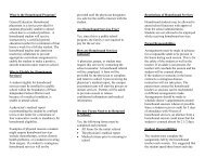
Ring Topology<br />
A<br />
Data<br />
Data<br />
Hub<br />
B<br />
Cable<br />
D<br />
In ring topology, a token travels from computer to computer until it<br />
reaches a node waiting to transmit data. The data then attaches to the<br />
token and is delivered to the receiving device. The token then continues<br />
around the ring looking for another device waiting to send data.<br />
Ring topology is easier to manage and maintain than bus topology, is more<br />
reliable than a bus, and it handles traffic well. On the negative side, it<br />
does require more cabling than a bus, especially if the computer devices<br />
are far apart. Expansion of a ring network disrupts data transmission for<br />
all.<br />
If your network has high traffic, and you are looking for a reliable network<br />
where each workstation has equal access, ring topology may be the answer.<br />
Token Ring and Fiber Distributed Data Interface (FDDI) networks use<br />
token passing ring topologies.<br />
Data<br />
Data<br />
ST0025803A Internetworking Fundamentals<br />
C
Unit 1: Internetworking Overview<br />
Star Topology<br />
Star topology is a point-to-point architectural design where all computer<br />
devices are connected to a central hub, through which all data signals must<br />
travel. There are both active and passive hubs. Passive hubs send data<br />
without amplification; active hubs amplify data signals.<br />
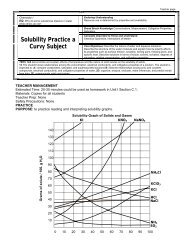
Star Topology<br />
A<br />
Data<br />
B<br />
Hub<br />
Star topology advantages:<br />
• Easy to install and upgrade<br />
Data<br />
• Easier to manage and maintain that bus and ring topologies<br />
• Central hub makes troubleshooting easy<br />
Star topology disadvantages:<br />
• Hub failure causes entire network to go down<br />
• More expensive for cabling<br />
In star networks, the logical transmittal of data is similar to bus topology<br />
but only one computer can transmit data at a time. The physical<br />
topologies are quite different. The physical hub of the star acts to logically<br />
connect all devices as if to a single cable segment. Star is the easiest<br />
topology to install, upgrade, and manage.<br />
ST0025803A<br />
D<br />
C<br />
101
102<br />
<strong>Lesson</strong> 1-4: <strong>Structured</strong> <strong>Cabling</strong> <strong>Systems</strong><br />
Computer devices are attached directly to central hubs via patch cable.<br />
Each patch cable connects to a port on the hub. Small hubs usually have 4,<br />
8, or 16 ports. Larger hubs may have up to 512 ports. <strong>Cabling</strong> is more<br />
expensive than for other topologies since each device must be connected<br />
directly to the hub<br />
When a device on a star topology network fails, it does not disrupt the<br />
other computer devices. Similarly, if you add a new device, service to other<br />
nodes continues uninterrupted. However, if the hub fails, the entire<br />
network goes down. 10BASE-T is one of the most popular star topology<br />
networks.<br />
Hybrid Network Topology<br />
Hybrid topology is any combination of bus, star, and ring topology, for<br />
example, a star-bus configuration. With a star-bus network, several hubs<br />
can be connected on a bus segment to several star topology segments.<br />
Hybrid Topology<br />
10BaseT<br />
LAN<br />
Router<br />
Switch<br />
Internet<br />
Token<br />
Ring<br />
10BaseT<br />
LAN<br />
More often than not, hybrid topology is commonplace in large networks<br />
because it is allows combining subnetworks, each employing the least<br />
expensive, most efficient topology.<br />
ST0025803A Internetworking Fundamentals
Unit 1: Internetworking Overview<br />
Check Your Understanding<br />
♦ List several factors an administrator must consider when planning<br />
a network.<br />
♦ Why must cable segments on a bus network be terminated?<br />
♦ What are some advantages of bus topology?<br />
♦ What is one major disadvantage of star topology?<br />
ST0025803A<br />
103
104<br />
Try It Out<br />
Network Topologies<br />
<strong>Lesson</strong> 1-4: <strong>Structured</strong> <strong>Cabling</strong> <strong>Systems</strong><br />
In the connectivity lesson, you diagramed all the devices and workstations<br />
connected to your network. When administrators design network<br />
topologies, they often use software applications to illustrate the topology.<br />
Using a computer, generate designs for four different network topologies,<br />
bus, ring, star, and hybrid topologies. Print out your networks and save in<br />
your portfolio.<br />
Materials Needed<br />
• Word processing application (e.g., MS Word)<br />
• Network diagram from <strong>Lesson</strong> 2<br />
• Actual network design from your instructor<br />
Open a word processing application. Directions shown here are for<br />
Microsoft Word 6.0. (If you use another word processing application, check<br />
with your instructor for vendor specific directions.)<br />
1. In the toolbar, click View. Scroll down to Toolbars and check Drawing.<br />
2. The following drawing toolbar will appear on the screen.<br />
3. Diagram and label a bus topology with at least five nodes.<br />
ST0025803A Internetworking Fundamentals
Unit 1: Internetworking Overview<br />
4. Highlight the Text box on the Drawing toolbar.<br />
5. Move the pointer to where you want to draw a box, which will represent<br />
the computers. The pointer changes to a crosshair. Hold down the left<br />
mouse button and drag to create the box. For each computer device in<br />
your diagram, draw a textbox.<br />
6. To move the textbox, bring the pointer to the edge of the box until it<br />
changes to a cross with arrows. Hold down the Shift key and move the<br />
box so it is where you want to place the computer.<br />
7. You can size the text box by bringing the pointer to the edge or corner<br />
of the box until the pointer turns to a two-sided arrow. Hold down the<br />
left mouse button and size your text box.<br />
8. Highlight the Line button on the Drawing toolbar.<br />
9. Draw in lines to connect the computer devices. Use the lines to create a<br />
bus topology. Label the diagram Bus Topology.<br />
10. Print your bus topology diagram and place it in your portfolio.<br />
11. Create three more diagrams. One for star, one for ring, and one for a<br />
hybrid topology. Put them in your portfolio.<br />
12. Contact your school’s network administrator and ask what type of<br />
network topology the school uses.<br />
13. Which type of topology does your school network use?<br />
14. Using the hand drawn diagram you created for the connectivity lesson,<br />
and the information you received from the school network<br />
administrator, create a computer diagram of how your school may be<br />
wired.<br />
15. Obtain the actual topology documentation for your school’s network<br />
from your teacher.<br />
16. Re-create the diagram to accurately reflect your school’s topology.<br />
ST0025803A<br />
105
106<br />
Rubric: Suggested Evaluation Criteria and Weightings<br />
<strong>Lesson</strong> 1-4: <strong>Structured</strong> <strong>Cabling</strong> <strong>Systems</strong><br />
Criteria % Your Score<br />
Active engagement 15<br />
Accurate computer diagram of a bus, star, ring,<br />
and hybrid topology.<br />
Labeled diagrams placed in portfolio 10<br />
Diagram of your school’s network topology 15<br />
TOTAL 100<br />
ST0025803A Internetworking Fundamentals<br />
60
Unit 1: Internetworking Overview<br />
Stretch Yourself<br />
Star Network<br />
In this lesson, you learned the different types of wiring topology for<br />
networks. You have to be connected to the network in order to transmit<br />
data. In the connectivity lesson, you installed a NIC. In this activity, you<br />
will design a star and bus network topology and experience what happens<br />
when a network connection is broken.<br />
Materials Needed<br />
• Cables<br />
• Networking equipment, e.g. a hub and several computers<br />
• Computer file enabled for sharing<br />
Star Network<br />
Work in groups of four and set up a star network.<br />
1. Verify that all four nodes are securely connected to the hub in a star<br />
format.<br />
2. Check the NIC connection on each workstation to be sure there is a<br />
secure connection. Have your instructor check your star network.<br />
3. Use one of the nodes as a server and the other three nodes as clients.<br />
Your instructor will tell you which computer will serve as the server<br />
and which will be the clients.<br />
4. Clients should access a folder from the server. Make sure that you are<br />
able to access and use the shared folder as specified by your instructor.<br />
5. Leave the folder open and remove the NIC connection from the server.<br />
♦ Record in the space below what happens.<br />
Answer: The connection will fail.<br />
♦ Explain why this happened. Are the other devices able to stay<br />
connected? Why?<br />
Answer: The computers are not longer connected together.<br />
6. Reconnect the computer to the network.<br />
♦ Are you still connected to the shared file?<br />
ST0025803A<br />
107
108<br />
Rubric: Suggested Evaluation Criteria and Weightings<br />
<strong>Lesson</strong> 1-4: <strong>Structured</strong> <strong>Cabling</strong> <strong>Systems</strong><br />
Criteria % Your Score<br />
Participation and teamwork 15<br />
Detailed notes of what happened when<br />
disconnected from the network<br />
Thoughtful analysis and comparison of bus and<br />
star networks<br />
Understanding of the OSI model and its<br />
relationship to this network activity<br />
TOTAL 100<br />
ST0025803A Internetworking Fundamentals<br />
25<br />
30<br />
30
Unit 1: Internetworking Overview<br />
Network Wizards<br />
Network Design<br />
Materials Needed<br />
• Spreadsheet application<br />
• Drawing application<br />
• Cable cost analysis prepared for Stretch Yourself, <strong>Lesson</strong> 3<br />
Work with a partner to create a list of questions you should ask a client<br />
who has hired you to build a network. The client wants to know which<br />
type of cable you plan to use and why, how much the cable will cost, and<br />
why you selected the particular topology. The client also wants you to<br />
submit a proposal that defends your choice of cabling and network design.<br />
After you create your questionnaire, role-play with your partner. One of<br />
you will assume the role of client, and the other the role of the network<br />
designer. The client will answer all the questions for a fictitious company<br />
of his/her choice. The network designer will record all of the answers.<br />
When the questionnaire is complete, you will both analyze the<br />
requirements and determine the appropriate topology. Create a computer<br />
diagram of the proposed network for the client. Prepare a spreadsheet that<br />
shows a cost analysis of the cable needed to complete the job. The cost<br />
analysis should include the type of cable, length of cable, cost of each type<br />
of cable, and the total cable cost. Use the cost information you gathered in<br />
the cabling lesson.<br />
Submit a proposal to the client indicating the suggested network topology.<br />
Include a summary to convince the client that this is the best, most cost<br />
efficient design for her/his needs. Your proposal must also defend your<br />
cable choices. Attach the computer diagram and cable cost analysis<br />
spreadsheet to your proposal.<br />
ST0025803A<br />
109
Summary<br />
110<br />
Rubric: Suggested Evaluation Criteria and Weightings<br />
<strong>Lesson</strong> 1-4: <strong>Structured</strong> <strong>Cabling</strong> <strong>Systems</strong><br />
Criteria % Your Score<br />
On time delivery of client proposal 10<br />
Computer diagram of proposed network 10<br />
Completeness of questionnaire 20<br />
Accurate analysis of client needs 20<br />
Accuracy and completeness of cable cost analysis<br />
spreadsheet<br />
Content and quality of client proposal 30<br />
TOTAL 100<br />
In this lesson, you learned the following:<br />
• To identify and describe the elements that are recommended for<br />
structured cabling networks.<br />
• To diagram bus, star, ring, and hybrid topologies.<br />
• To compare and contrast the advantages and disadvantages of bus,<br />
star, ring, and hybrid topologies.<br />
• To select the appropriate topology for a particular set of network<br />
requirements.<br />
• To create a questionnaire for an administrator to use when planning or<br />
expanding a network.<br />
• To select and estimate the cost of cabling for a given network.<br />
ST0025803A Internetworking Fundamentals<br />
10
Unit 1: Internetworking Overview<br />
Review Questions Name___________________<br />
<strong>Lesson</strong> 1-4: <strong>Structured</strong> <strong>Cabling</strong> <strong>Systems</strong><br />
Part A<br />
1. When planning a network, an administrator must<br />
a. Anticipate the potential for future growth.<br />
b. Take an inventory of existing hardware and software.<br />
c. Determine the needs of the organization.<br />
d. Determine the best physical and logical topology.<br />
e. All of the above.<br />
2. <strong>Cabling</strong> that carries the signals from equipment room to equipment<br />
room, between floors and the building entrance cabling.<br />
a. Patch cable<br />
b. Backbone cable<br />
c. Horizontal cable<br />
d. All of the above<br />
3. What is the office space where computers are located called?<br />
a. Work area<br />
b. Equipment room<br />
c. Building entrance<br />
d. Horizontal cabling room<br />
e. Backbone cabling room<br />
ST0025803A<br />
111
112<br />
<strong>Lesson</strong> 1-4: <strong>Structured</strong> <strong>Cabling</strong> <strong>Systems</strong><br />
4. The cabling that carries the signals from the equipment room to the<br />
various work areas.<br />
a. Workstation cabling<br />
b. Patch cabling<br />
c. Horizontal cabling<br />
d. Backbone cabling<br />
5. Electromagnetic interference is not a problem for which cable?<br />
a. Category 5 UTP<br />
b. STP cable<br />
c. Coaxial cable<br />
d. Fiber optic cable<br />
6. List five networking elements covered by the TIA/EIA 568 standards.<br />
Part B<br />
1. Diagram a bus network topology.<br />
2. Diagram a star network topology.<br />
3. Diagram a ring network topology.<br />
Part C<br />
1. List the advantages and disadvantages of bus network topology.<br />
2. List the advantages and disadvantages of star topology.<br />
3. List the advantages and disadvantages of ring topology.<br />
ST0025803A Internetworking Fundamentals
Unit 1: Internetworking Overview<br />
Part D<br />
1. You have been asked to create a network for five computers. Low cost<br />
is important and it is unlikely that the network will expand. Which<br />
network topology would you recommend and why?<br />
2. Which topology would you recommend for a network that will be<br />
reconfigured frequently, must be very reliable, and is easy to<br />
troubleshoot without bringing down the entire network? Why?<br />
3. You are designing a network for an automobile factory. There are lots<br />
of motors and fluorescent lights. Cost is not a factor. Each of the<br />
workstations must have equal access to the network. Which topology<br />
would you choose? Why?<br />
4. Refer to question number 3. Which type of cable would you recommend<br />
for this network? Why?<br />
ST0025803A<br />
113
Scoring<br />
Rubric: Suggested Evaluation Criteria and Weightings<br />
114<br />
<strong>Lesson</strong> 1-4: <strong>Structured</strong> <strong>Cabling</strong> <strong>Systems</strong><br />
Criteria % Your Score<br />
Part A: Identify and describe the elements that are<br />
recommended for structured cabling networks<br />
Part B: Diagram and explain bus, star, ring, and hybrid<br />
topologies.<br />
Part C: Compare and contrast the advantages and<br />
disadvantages of bus, star, ring, and hybrid topologies.<br />
Part D: Select the appropriate topology for a particular set of<br />
network requirements<br />
TOTAL 100<br />
Try It Out Diagram and explain bus, star, ring, and hybrid<br />
topologies.<br />
ST0025803A Internetworking Fundamentals<br />
25<br />
25<br />
25<br />
25<br />
100<br />
Stretch Yourself 100<br />
Network Wizards Questionnaire and estimate 100<br />
FINAL TOTAL 400<br />
References<br />
Aschermann, Robert (1998). MCSE Networking Essentials for Dummies.<br />
IDG Books Worldwide, Inc. Foster City, California.<br />
Bert, Glen (1998). MCSE Networking Essentials: Next Generation<br />
Training Second Edition. New Riders Publishing Indianapolis, Indiana.<br />
Carol, J. T. & Love, R.D. (1995). Dedicated Token Ring. In The Token<br />
Ring Consortium Report [Online]. University of New Hamphsire<br />
InterOperability Labs. Available:<br />
www.iol.unh.edu/consortiums/tokenring/MACs_n_PHYs/Fall95/Special_Feature.ht<br />
ml. [1999, April 30].<br />
Chellis, James; Perkins, Charles; & Strebe, Matthew (1997). MCSE<br />
Networking Essentials Study Guide. Sybex Inc., Alameda, California.<br />
Derfler, Jr., Frank J., & Freed, L. (1998). How Networks Work, Fourth<br />
Edition. Macmillan Computer Publishing/Que Corporation, Indianapolis,<br />
Indiana.
Unit 1: Internetworking Overview<br />
Hayden, Matt. (1998). Sam's Teach Yourself Networking in 24 Hours.<br />
Sam's Publishing, Indianapolis, Indiana.<br />
HDS Network <strong>Systems</strong>, Inc. (1996). IEEE 802.3 Ethernet type. In HDS<br />
@workStation System Administrator’s Guide [Online]. Available:<br />
www.rzu.unizh.ch/nw/lwp/xhds/hdsdocs/netOS20/htmlsysadmin [1999, May 13].<br />
Lantronix. (1999). Ethernet Tutorial. In Technology Tutorials [Online].<br />
Available: www.lantronix.com/technology/tutorials [1999, April 20].<br />
Lindsay, S., Rosenblum, D. & Walleigh, W. (1998). Token Ring Switching.<br />
In Technology [Online]. 3Com Corporation. Available:<br />
www.3com.com/nsc/500603.ntml [1999, April 30].<br />
Lowe, Doug. (1998). Networking for Dummies. Third Edition. IDG Books<br />
Worldwide, Inc., Foster City, California.<br />
Microsoft Corporation (1998). Dictionary of Computer Terms, Microsoft<br />
Press, Redmond, Washington.<br />
Nortel Networks (1998). Internetworking Fundamentals: Student Guide.<br />
Bay Networks Inc. Billerica, Massachusetts.<br />
Palmer, Michael J. (1998) Hands-On Networking Essentials with Projects,<br />
Course Technology, Inc. Cambridge, Massachusetts.<br />
Spurgeon, Charles E. (1997). Practical Networking With Ethernet,<br />
International Thomson Computer Press, Boston, Massachusetts.<br />
Spurgeon, Charles. (1993-1995). Quick Reference Guide to Ethernet<br />
[Online]. University of Texas Office of Telecommunications. Available:<br />
www.ots.utexas.edu/ethernet/descript-10quickref.html [1999, April 20].<br />
ST0025803A<br />
115
116<br />
<strong>Lesson</strong> 1-4: <strong>Structured</strong> <strong>Cabling</strong> <strong>Systems</strong><br />
ST0025803A Internetworking Fundamentals