Using FEMM software tool - Università di Padova
Using FEMM software tool - Università di Padova
Using FEMM software tool - Università di Padova

Create successful ePaper yourself
Turn your PDF publications into a flip-book with our unique Google optimized e-Paper software.
<strong>Using</strong> <strong>FEMM</strong> <strong>software</strong> <strong>tool</strong><br />
Electric Drive Laboratory<br />
May 10, 2006<br />
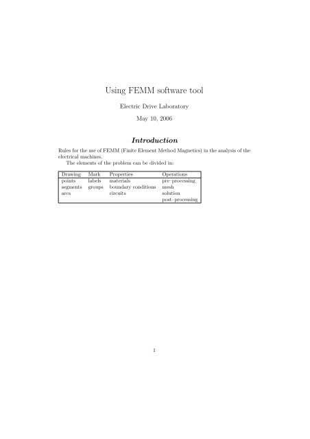
Introduction<br />
Rules for the use of <strong>FEMM</strong> (Finite Element Method Magnetics) in the analysis of the<br />
electrical machines.<br />
The elements of the problem can be <strong>di</strong>vided in:<br />
Drawing Mark Properties Operations<br />
points labels materials pre–processing<br />
segments groups boundary con<strong>di</strong>tions mesh<br />
arcs circuits solution<br />
post–processing<br />
1
Nicola Bianchi <strong>Using</strong> <strong>FEMM</strong><br />
Part I<br />
Simple examples<br />
1 A first example: the electromagnetic actuator<br />
Let us consider the electromagnetic actuator of Fig. 1. It includes a fixed iron yoke<br />
around which a coil is wound, and an iron plate. When the coil carries current, the<br />
iron yoke attracts the iron plate, due to the magnetic pressure on its surface.<br />
Neglecting the end effects, the simulation is carried out by assuming a planar<br />
symmetry. This is that all the magnetic fields are repeated equal for each section of<br />
the electromagnetic actuator. Then an unitary length is assumed, that is, Lstk=1 m.<br />
1.1 Problem setting<br />
Figure 1: Sketch of the electromagnetic actuator<br />
The first step is to define the problem:<br />
Type: the symmetry is planar,<br />
Units: the unity is millimeter,<br />
Frequency: since this is a magneto–static problem, the frequency is set to be zero,<br />
Depth: a unity length is selected (this corresponds to 1000 mm).<br />
1.2 Drawing<br />
At first all the points of the structure are drawn, as shown in Fig. 2. The points can<br />
be chosen by using the mouse (in this case it is suggested to use the snap to the grid)<br />
or by using the keyboard (press TAB and insert the point coor<strong>di</strong>nates).<br />
2
Nicola Bianchi <strong>Using</strong> <strong>FEMM</strong><br />
Figure 2: Points of the drawing<br />
After drawing the points, they have to be connected by segments. Select two<br />
points at a time by the left bottom of the mouse, so that they are connected together.<br />
Fig. 3 shows the segments that connect the points of Fig. 2.<br />
Figure 3: Segments of the drawing<br />
At this point the drawing of the structure is completed.<br />
1.3 Boundary con<strong>di</strong>tions<br />
In a field problem, the the magnetic fields are required to satisfy suitable con<strong>di</strong>tions<br />
on the boundary of the domain. These con<strong>di</strong>tions are called boundary con<strong>di</strong>tions. In<br />
a two–<strong>di</strong>mensional problem, they are imposed along the segments of the border.<br />
There are four main boundary con<strong>di</strong>tions:<br />
Dirichlet: this con<strong>di</strong>tion prescribes a given value of the magnetic vector potential Az<br />
3
Nicola Bianchi <strong>Using</strong> <strong>FEMM</strong><br />
along a segment. Thus, the flux lines results tangential to this segment. This<br />
con<strong>di</strong>tion is used to confine the field lines into the domain.<br />
Neumann: this con<strong>di</strong>tion imposed the flux density lines to be normal to the selected<br />
segment. This con<strong>di</strong>tion is a natural con<strong>di</strong>tion. This means that it is<br />
automatically satisfied, if other con<strong>di</strong>tions are not assigned.<br />
Perio<strong>di</strong>c: this con<strong>di</strong>tion is assigned to two segments and imposes that the magnetic<br />
vector potential behavior is the same along the two segments, i.e. Az,segment1 =<br />
Az,segment2.<br />
Anti–perio<strong>di</strong>c: this con<strong>di</strong>tion is assigned to two segments and imposes that the<br />
magnetic vector potential behavior is the one opposite to the other along the<br />
two segments, i.e. Az,segment1 = −Az,segment2.<br />
It is worth noticing that the boundary con<strong>di</strong>tions are defined to confine the field<br />
analysis to a given region, reducing the domain as minimum as possible.<br />
In this specific problem, it will be assigned that no flux lines can cross this boundary:<br />
1. A boundary con<strong>di</strong>tion Az = 0 is defined in the problem.<br />
2. The external lines, that is, the segments of the box are selected, using the right<br />
bottom of the mouse.<br />
3. The boundary con<strong>di</strong>tion is assigned.<br />
1.4 Materials<br />
The material of the objects that form the structure have to be defined. They can be<br />
new materials, suitably defined for this analysis, or they can be selected from a given<br />
Material Library. This includes the commonly used materials.<br />
In the example, the materials that are used are Air, Iron and Copper.<br />
A label is defined for each object. Then, the appropriate material is assigned to<br />
the object: Iron is assigned to the two magnetic pieces, Copper is assigned to the two<br />
coil sides, and Air is assigned to the remanent space.<br />
Fig. 4 shows the label of the electromagnetic actuator.<br />
1.5 Mesh<br />
The sub<strong>di</strong>vision of the structure in finite elements is automatic. This process is<br />
commonly called ”to create the mesh”. Each object will be sub<strong>di</strong>vided in small<br />
elements (the finite element), which are triangles in <strong>FEMM</strong>.<br />
It is possible to force the maximum mesh size in each object. The mesh size<br />
refers to the area of the triangle used for this sub<strong>di</strong>vision. The choice of the mesh<br />
size depends on the problem to be analyzed. It is better to refine the parts of the<br />
problem, in which the higher field gra<strong>di</strong>ents are expected.<br />
Fig. 5 shows the final mesh of the electromagnetic actuator.<br />
4
Nicola Bianchi <strong>Using</strong> <strong>FEMM</strong><br />
1.6 Current sources<br />
Figure 4: Labels of the drawing<br />
Figure 5: Mesh of the structure<br />
The current is imposed in the coil sides by defining two current sources, or circuits.<br />
In our example, we define two circuits:<br />
CurrentPos: the positive current, for instance equal to 100 A.<br />
CurrentNeg: the negative current, whose value has to be –100 A.<br />
After their definition, they are assigned to the two coils of the structure, as shown<br />
in Fig. 6.<br />
5
Nicola Bianchi <strong>Using</strong> <strong>FEMM</strong><br />
1.7 Groups<br />
Figure 6: External circuits connected to the coil sides<br />
A group of objects can be defined to belong to the same group, defined by an identification<br />
number. The group can also contain one object only.<br />
The group definition is useful when the automatic analysis is adopted, as will be<br />
shown when the script files are dealt with.<br />
In this example, we define the upper coil side as group 1001, the lower coil side as<br />
group 1002 and the moving keeper as group 10.<br />
1.8 Plot<br />
Once all the steps above have been completed, the problem is ready to be solved. The<br />
problem is analyzed. Then the results can be<br />
At first the flux lines are plotted as shown in Fig. 7. This plot give us a rapid idea<br />
if the problem has been correctly set.<br />
A further visual analysis refers to the flux density map, shown in Fig. 8. This<br />
gives an in<strong>di</strong>cation of the range of flux density values reached in the structure.<br />
2 Use of the LUA script<br />
The purpose of the LUA file is to automatize a series of computations using the<br />
<strong>FEMM</strong> code.<br />
A series of instructions can be written in a unique file (the LUA file) and they are<br />
executed consecutively when the file is read within a <strong>FEMM</strong> e<strong>di</strong>tor or viewer. Often<br />
a FOR loop is implemented, in which one or two parameters are changed.<br />
This kind of programming is useful when several simulations have to be carried<br />
out searching the dependence of the machine performance on one parameter, e.g. the<br />
working frequency, the operating currents, or the geometrical position.<br />
Some examples are given in the following. Further informations and documen-<br />
6
Nicola Bianchi <strong>Using</strong> <strong>FEMM</strong><br />
Figure 7: Flux lines of the solved structure<br />
Figure 8: Flux density map of the solved structure<br />
tation can be found in the chapter ”LUA Scripting Documentation” of the ”<strong>FEMM</strong><br />
User’s Manual” (Press key Help topics in the menu Help of the application.<br />
2.1 Scripts for the Pre–processing<br />
An example is given to mo<strong>di</strong>fy the current of the circuits.<br />
At first we could need to compute the maximum current from the geometrical<br />
data<br />
S_coil = 600 -- (mm2)<br />
k_fill = 0.4<br />
J_max = 6 -- (A/mm2)<br />
I_max = S_coil * J_max<br />
7
Nicola Bianchi <strong>Using</strong> <strong>FEMM</strong><br />
\begin{verbatim}<br />
%<br />
where the text following \verb"--" is a comment.<br />
Then a series of analysis at various currents can be implemented as<br />
follows. Ten simulations are considered with linear variation of the<br />
current:<br />
\begin{verbatim}<br />
N_sim = 10<br />
for n = 1, (N_sim + 1), 1 do<br />
I_coil = I_max * (n - 1) / N_sim<br />
Once the value of the current is computed, the correspond circuits have to be<br />
mo<strong>di</strong>fied. The instructions that have to be used are<br />
mo<strong>di</strong>fycircprop("CurrentPos", 1, I_coil)<br />
mo<strong>di</strong>fycircprop("CurrentPos", 1, -I_coil)<br />
It is also convenient to operate as follows:<br />
1. to open an original <strong>FEMM</strong> file,<br />
2. to mo<strong>di</strong>fy as required,<br />
3. to save in a temporary <strong>FEMM</strong> file, which becomes a copy of the original project<br />
but with the mo<strong>di</strong>fications, and<br />
4. to analyze the temporary <strong>FEMM</strong> file.<br />
In this way, the original file is not mo<strong>di</strong>fied. The LUA code becomes<br />
openfemmfile("electromagnet.fem")<br />
mo<strong>di</strong>fycircprop("CurrentPos", 1, I_coil)<br />
mo<strong>di</strong>fycircprop("CurrentPos", 1, -I_coil)<br />
savefemmfile("tempfile.fem ")<br />
analyse()<br />
A copy of the original project ”electromagnet.fem” to save in the temporary file<br />
”tempfile.fem”, with the mo<strong>di</strong>fications implemented. This allows the original project<br />
to remain unchanged.<br />
The command analyse() start the finite element computation.<br />
8
Nicola Bianchi <strong>Using</strong> <strong>FEMM</strong><br />
2.2 From Pre– to Post–processing<br />
Sometimes there is the needs to transfer one or more data from the pre–processing<br />
to the post–processing. This can be accomplished by write the information in a text<br />
file that will be read when the post–processing will run.<br />
An example of writing (e.g. the value of the current of the coil) in the ”temp.txt”<br />
file is<br />
handle = openfile("temp.txt", "w");<br />
write (handle, I_coil, "\n");<br />
closefile(handle);<br />
Finally, once the problem is analyzed, it is necessary that the solved problem is<br />
processed. Then the last command within the FOR loop of the pre–processing file<br />
is the call to the post–process LUA file. This procedure will be described in the<br />
following subsection. It is called as follows<br />
runpost("postprocess.lua")<br />
All the command that have written in the file ”postprocess.lua” will be executed.<br />
Then the complete ”preprocess.lua” becomes<br />
S_coil = 600 -- (mm2)<br />
k_fill = 0.4<br />
J_max = 6 -- (A/mm2)<br />
I_max = S_coil * J_max<br />
N_sim = 10<br />
for n = 1, (N_sim + 1), 1 do<br />
I_coil = I_max * (n - 1) / N_sim<br />
openfemmfile("electromagnet.fem")<br />
mo<strong>di</strong>fycircprop("CurrentPos", 1, I_coil)<br />
mo<strong>di</strong>fycircprop("CurrentPos", 1, -I_coil)<br />
savefemmfile("tempfile.fem ")<br />
analyse()<br />
handle = openfile("temp.txt", "w");<br />
write (handle, I_coil, "\n");<br />
closefile(handle);<br />
runpost("postprocess.lua")<br />
end<br />
2.3 Post–processing<br />
The post–processing file contains the instructions that have to executed after the field<br />
problem has been solved. This file can be called separately or can be launched by the<br />
pre–processing, for instance when it is included within an analysis loop.<br />
At first, the value of some parameters are assigned, e.g. the z–axis length and the<br />
number of turns of the coil:<br />
9
Nicola Bianchi <strong>Using</strong> <strong>FEMM</strong><br />
-- length (m)<br />
L_z = 0.100<br />
-- number of turns<br />
N_t = 80<br />
The first operation of the post–process is to read the data written in the temporary<br />
file during the pre–processing.<br />
handle = openfile("temp.txt", "r");<br />
I_coil = read (handle, "*n");<br />
closefile(handle);<br />
Then, some operations are executed. The same conventions used in the pre–<br />
processing have to be of course used. Some examples are reported hereafter.<br />
Each operation is <strong>di</strong>vided in two steps:<br />
1. at first, an element (line, object, group) or a set of elements is selected,<br />
2. an operation is executed referring to this element or this set of elements.<br />
In the following example, the line on the top of the moving keeper is selected by<br />
means of the two extremes of the line. Then the computation of the force along the<br />
line is required. Fcx and Fcy are the constant component of the force along the x<br />
and y <strong>di</strong>rections respectively, while Fpx and Fpy are the pulsating force components<br />
along the x and y <strong>di</strong>rections respectively. The latter components are equal to zero in<br />
magneto–static problems.<br />
sete<strong>di</strong>tmode(contour)<br />
selectpoint(-60, -10)<br />
selectpoint( 60, -10)<br />
F_cx, F_px, F_cy, F_py = lineintegral(3)<br />
Alternatively, the moving iron keeper could be selected by means of its group<br />
number 10, and the force components are achieved from the Maxwell stress tensor:<br />
groupselectblock(10)<br />
F_cx = blockintegral(18)<br />
F_cy = blockintegral(19)<br />
F_px = blockintegral(20)<br />
F_py = blockintegral(21)<br />
In the following example, the flux linkage with the coil is computed. The two<br />
coils can be selected by means their group number (1001 and 1002 for the upper<br />
and the lower coil side respectively). The coil side surface is firstly computed. Then<br />
the magnetic potential is integrated over the two surfaces, and the flux linkage is<br />
computed from their <strong>di</strong>fference.<br />
10
Nicola Bianchi <strong>Using</strong> <strong>FEMM</strong><br />
-- surface<br />
groupselectblock(1001)<br />
Sup = blockintegral(5)<br />
clearblock()<br />
-- integral of Az<br />
groupselectblock(1001)<br />
intg_Are_1, intg_Aim_1 = blockintegral(1)<br />
clearblock()<br />
groupselectblock(1002)<br />
intg_Are_2, intg_Aim_2 = blockintegral(1)<br />
clearblock()<br />
-- flux linkage<br />
flux_re_1 = (intg_Are_1 / Sup) * L_z * N_t<br />
flux_im_1 = (intg_Aim_1 / Sup) * L_z * N_t<br />
flux_re_2 = (intg_Are_2 / Sup) * L_z * N_t<br />
flux_im_2 = (intg_Aim_2 / Sup) * L_z * N_t<br />
In order to compute the magnetic energy all the elements of the domain are selected.<br />
No number is specified in the command groupselectblock() so as all blocks<br />
are selected. Then, magnetic energy density, magnetic coenergy density and the product<br />
A · J are integrated.<br />
groupselectblock()<br />
Energy = blockintegral(2)<br />
Coenergy = blockintegral(17)<br />
AJ_intgr = blockintegral(0)<br />
Once the computation is finished, the results have to be stored into a file. The<br />
file ”results.txt” is open to append (note the command ”a”) the results of the computation.<br />
In the example hereafter the values are written on the same row, spaced by<br />
some blank spaces, followed by a line end command (”\n”).<br />
handle = openfile("results.txt", "a")<br />
write(handle,<br />
I_coil, " ",<br />
F_cx, " ",<br />
F_cy, " ",<br />
flux_re_1, " ",<br />
flux_im_1, " ",<br />
flux_re_2, " ",<br />
flux_im_2, " ",<br />
Energy, " ",<br />
Coenergy, " ",<br />
AJ_intgr,<br />
11
Nicola Bianchi <strong>Using</strong> <strong>FEMM</strong><br />
"\n")<br />
closefile(handle)<br />
At last, the view e<strong>di</strong>tor is closed:<br />
exitpost()<br />
3 A second example: a cylindrical actuator<br />
Accor<strong>di</strong>ng to the cylindrical actuator shown in Fig. 3, the pre– and post–processing<br />
files are reported in the following.<br />
The pre–processing is<br />
(a) Pre–processor (b) Post–processor<br />
Figure 9: Actuator<br />
PRE_ATT.LUA<br />
-- Current density is defined<br />
jm=3<br />
handle = openfile("result.txt", "a");<br />
write(handle, jm, " ");<br />
12
Nicola Bianchi <strong>Using</strong> <strong>FEMM</strong><br />
closefile(handle)<br />
-- Loop of simulations varying the air--gap thickness<br />
-- dz is the variation with respect to the initial position<br />
for dz = 0,-0.6,-0.2 do<br />
-- Its value is stored in the result file<br />
handle = openfile("result.txt", "a");<br />
write(handle, dz, " ");<br />
closefile(handle)<br />
-- The actuator structure is loaded<br />
open_femm_file("actuator.fem")<br />
-- The current density is assigned to the coil<br />
mo<strong>di</strong>fymaterial("Copper", 4, jm)<br />
-- Mover (group=1) is selected and moved<br />
selectgroup(1)<br />
move_translate(0, dz)<br />
-- The changed structure is save in a temporary file<br />
save_femm_file("temp.fem")<br />
-- Solving the problem<br />
analyse(1) -- (0) show window<br />
-- (1) hide window<br />
-- Post-processing<br />
runpost("post_att.lua", "-windowhide")<br />
end<br />
The post–processing is<br />
POST_ATT.LUA<br />
-- selection of the line to integrate the flux density<br />
sete<strong>di</strong>tmode(contour)<br />
selectpoint(0,10.5)<br />
selectpoint(3,10.5)<br />
Flux, B_avg = lineintegral(1)<br />
-- unselection<br />
clearcontour()<br />
-- Data storage<br />
handle = openfile("result.txt", "a");<br />
write(handle, Flux, " ",<br />
B_avg, "\n")<br />
closefile(handle)<br />
-- post-processing end<br />
exitpost()<br />
13
Nicola Bianchi <strong>Using</strong> <strong>FEMM</strong><br />
4.1 Mathematic functions<br />
4.2 Vectors<br />
4 Useful functions<br />
sin(x) Sine of x<br />
cos(x) Cosine of x<br />
tan(x) Tangent of x<br />
asin(x) Inverse sine of x [−π/2, π/2], x ɛ [−1, 1]<br />
acos(x) Inverse cosine of x [0, π], x ɛ [−1, 1]<br />
atan(x) Inverse tangent of x [−π/2, π/2]<br />
atan2(x, y) Inverse tangent of x/y [−π, π]<br />
sinh(x) Hyperbolic sine of x<br />
cosh(x) Hyperbolic cosine of x<br />
tanh(x) Hyperbolic tangent of x<br />
esp(x) Exponential e x<br />
log(x) Natural logarithm of x, with x¿0<br />
log10(x) Common (base 10) logarithm of x, with x¿0<br />
pow(x, y) Power x y<br />
sqrt(x) Square root √ x<br />
ceil(x) Round towards plus infinity of x<br />
floor(x) Round towards minus infinity of x<br />
abs(x) Absolute value of x<br />
When a vector of numbers has to be defined, we can use the curly brackets. For<br />
instance, a vector of three number is<br />
Vector = {number1, number2, number3}<br />
The values of the vector are gained by using the squared brackets:<br />
number1 = Vector[1]<br />
number2 = Vector[2]<br />
number3 = Vector[3]<br />
4.3 Indexed variables<br />
Sometimes it is needed to adopt some variables whose name has a common root<br />
followed by a varying number.<br />
For example, CoilSide1 and CoilSide2 that are used in the first example.<br />
These names can be obtained by link the common root CoilSide2 with an index<br />
that assumes the numerical value 1 and 2. The link is achieved as<br />
"CoilSide" .. index<br />
14
Nicola Bianchi <strong>Using</strong> <strong>FEMM</strong><br />
Acknowledgment<br />
This report has been possible thanks to contribution of many students and PhD students<br />
of the Electric Drive Laboratory of the Department of Electrical Engineering,<br />
University of <strong>Padova</strong>, Italy. In particular, the big work of PhD. Eng. Fabio Luise,<br />
PhD. Eng. Giorgio Grezzani, Eng. Diego Bon and Eng. Michele Dai Prè is acknowledged.<br />
Contacts<br />
Prof. Nicola Bianchi, Prof. Silverio Bolognani, Electric Drive Laboratory, Department<br />
of Electrical Engineering, University of <strong>Padova</strong>, Via Gradenigo 6 A <strong>Padova</strong>,<br />
Italy. Phone: +39 049 827 7500, Fax: +39 049 827 7599, email: [bianchi] [bolognani]<br />
@<strong>di</strong>e.unipd.it.<br />
15