4 Final Report - Emits - ESA
4 Final Report - Emits - ESA 4 Final Report - Emits - ESA
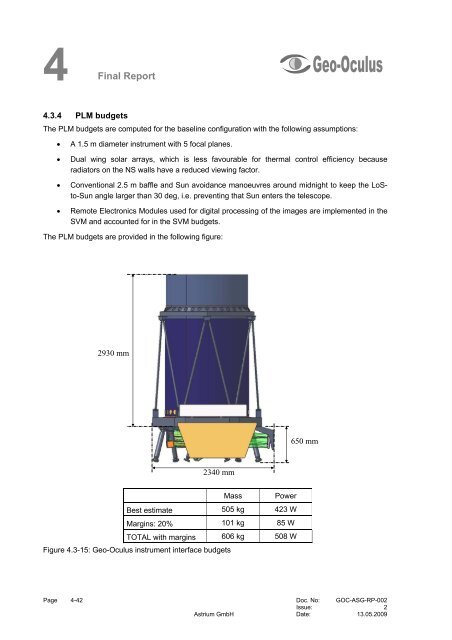
4 Final Report 4.3.4 PLM budgets The PLM budgets are computed for the baseline configuration with the following assumptions: • A 1.5 m diameter instrument with 5 focal planes. • Dual wing solar arrays, which is less favourable for thermal control efficiency because radiators on the NS walls have a reduced viewing factor. • Conventional 2.5 m baffle and Sun avoidance manoeuvres around midnight to keep the LoSto-Sun angle larger than 30 deg, i.e. preventing that Sun enters the telescope. • Remote Electronics Modules used for digital processing of the images are implemented in the SVM and accounted for in the SVM budgets. The PLM budgets are provided in the following figure: 2930 mm 2340 mm Mass Power Best estimate 505 kg 423 W Margins: 20% 101 kg 85 W TOTAL with margins 606 kg 508 W Figure 4.3-15: Geo-Oculus instrument interface budgets 650 mm Page 4-42 Doc. No: GOC-ASG-RP-002 Issue: 2 Astrium GmbH Date: 13.05.2009
4 Final Report 4.4 Line of Sight (LoS) Stabilisation Concepts 4.4.1 LoS stabilisation main issues: microvibrations and post-integration The LoS pointing stability requirements are very stringent for the aspects of the mission involving high resolution imaging. This is particularly the case during PAN imaging for disaster monitoring, since the 20 m resolution over Europe corresponds to 0.28 µrad nadir resolution, and to a lower extent when acquiring full resolution VNIR images (40 m resolution over Europe, 0.56 µrad nadir resolution) for disaster or fire monitoring. Image quality is then highly sensitive to LoS motion over the short integration time (up to ~100 msec) required to meet the moderate SNR requirements. On the contrary, the Marine applications, with a resolution relaxed to 80 m over Europe (i.e. 1.1 µrad nadir), are less sensitive to pointing stability over the image integration time. Nevertheless, since several images need to be post-integrated to reach high SNR requirements, image quality is more sensitive to pointing drifts over the total image acquisition time (several sec). LoS Stabilisation requirements derived from instrument design are summarised in the following table: RPE: Relative Pointing Error (stability over the integration time) RME: Relative Measurement Error (over image acquisition time) PDE: Pointing Drift Error (drift over integration time) 0.15-0.2 µrad peak-to-peak for high frequency jitter (>10 Hz) 0.1 µrad over 5 s max. acquisition time Marine applications: 10 µrad/s Fire/Disaster monitoring: 5 µrad/s Such specifications can not be met without proper management of the LoS pointing stability issue. Depending on the type of disturbances that challenge the LoS stability requirements, and in particular depending on the frequency band affected, different solutions might be proposed for Geo-Oculus : • High frequency perturbations, with period lower than typical integration time (100 msec), i.e. frequency > 10 Hz, require disturbance reduction techniques. Such disturbances are mainly due to microvibrations generated by moving parts (e.g. reaction wheels and cryocoolers). • Medium frequency disturbances (with period in the range of a few sec, corresponding to the time to acquire an image based on accumulation of several shots) require image processing techniques to enable post-integration. Such disturbances are mainly due to solar array flexible mode excitation after slew manoeuvres. • Low frequency disturbances are handled by the AOCS for those observed by the attitude sensors and by ground-based processing (so-called INR, Image Navigation & Registration) for LoS pointing errors due to orbit errors and thermo-elastic distortions between LoS and AOCS reference. Therefore, the LoS stabilisation issues to be addressed are: • Microvibrations: level reduction through careful selection of actuators and identification of potential other disturbances. • Post-integration: Evaluation of the technique to be used to estimate the shift between one image and another one before adding them. Doc. No: GOC-ASG-RP-002 Page 4-43 Issue: 2 Date: 13.05.2009 Astrium GmbH
- Page 7: DL Final Distribution List Report Q
- Page 11 and 12: TOC Final Table of Content Report D
- Page 13 and 14: 1 Final Report 1 Introduction 1.1 S
- Page 15: 1 Final Report [RD 7] Candidate Mis
- Page 18 and 19: 2 Final Report capability of existi
- Page 20 and 21: 2 Final Report Figure 2.3-1: Flood
- Page 22 and 23: 2 Final Report Figure 2.3-3: Algal
- Page 24 and 25: 2 Final Report Figure 2.3-6: Chloro
- Page 26 and 27: 2 Final Report Erosion / Sediment T
- Page 28 and 29: 3 Final Report 3 System Requirement
- Page 30 and 31: 3 Final Report Furthermore, the mis
- Page 32 and 33: 3 Final Report better than 0.5 SSD
- Page 34 and 35: 3 Final Report • Image post integ
- Page 36 and 37: 3 Final Report Table 3.3-1: Baselin
- Page 38 and 39: 3 Final Report Manoeuvre Times and
- Page 40 and 41: 3 Final Report Cloud Amount [%] Num
- Page 42 and 43: 3 Final Report cloud scenes where t
- Page 44 and 45: 4 Final Report Alternative solution
- Page 46 and 47: 4 Final Report The achieved ground
- Page 48 and 49: 4 Final Report board image processi
- Page 50 and 51: 4 Final Report 4.3.3.2 UV-VNIR foca
- Page 52 and 53: 4 Final Report Column decoder 4 out
- Page 54 and 55: 4 Final Report 4.3.3.5 Mechanical a
- Page 56 and 57: 4 Final Report 4.3.3.7 Electrical a
- Page 60 and 61: 4 Final Report 4.4.2 Microvibration
- Page 62 and 63: 4 Final Report Figure 4.4-2: Struct
- Page 64 and 65: 4 Final 4.5 Satellite Report 4.5.1
- Page 66 and 67: 4 Final Report Star Tracker Figure
- Page 68 and 69: 4 Final Report (Spacecraft Computer
- Page 70 and 71: 4 Final Report This is based on a w
- Page 72 and 73: 4 Final Report Reception of the ins
- Page 74 and 75: 4 Final Report Table 4.5-2: Charact
- Page 76 and 77: 4 Final Report Table 4.5-4: Compari
- Page 78 and 79: 4 Final Report Table 4.5-5: EPS fue
- Page 80 and 81: 4 Final Report manoeuvre. It also h
- Page 82 and 83: 4 Final Report Figure 4.5-10: Basel
- Page 84 and 85: 4 Final Report The CPS considered f
- Page 86 and 87: 4 Final Report PPU B* FU XST Page 4
- Page 88 and 89: 4 Final Report Table 4.5-17. EP mas
- Page 90 and 91: 4 Final Report The primary structur
- Page 92 and 93: 4 Final Report Direction MTG Scaled
- Page 94 and 95: 4 Final Report 4.6.1.1 High Level F
- Page 96 and 97: 4 Final Report shorter. As a conseq
- Page 98 and 99: 4 Final Report 4.6.2.4 Cloud Cover
- Page 100 and 101: 4 Final Report management functions
- Page 102 and 103: 4 Final Report 4.6.2.8 Ground Stati
- Page 104 and 105: 5 Final Report based on EUMETSAT im
- Page 107 and 108: A Final Report Annex A Abbreviation
4 <strong>Final</strong><br />
<strong>Report</strong><br />
4.3.4 PLM budgets<br />
The PLM budgets are computed for the baseline configuration with the following assumptions:<br />
• A 1.5 m diameter instrument with 5 focal planes.<br />
• Dual wing solar arrays, which is less favourable for thermal control efficiency because<br />
radiators on the NS walls have a reduced viewing factor.<br />
• Conventional 2.5 m baffle and Sun avoidance manoeuvres around midnight to keep the LoSto-Sun<br />
angle larger than 30 deg, i.e. preventing that Sun enters the telescope.<br />
• Remote Electronics Modules used for digital processing of the images are implemented in the<br />
SVM and accounted for in the SVM budgets.<br />
The PLM budgets are provided in the following figure:<br />
2930 mm<br />
2340 mm<br />
Mass Power<br />
Best estimate 505 kg 423 W<br />
Margins: 20% 101 kg 85 W<br />
TOTAL with margins 606 kg 508 W<br />
Figure 4.3-15: Geo-Oculus instrument interface budgets<br />
650 mm<br />
Page 4-42 Doc. No: GOC-ASG-RP-002<br />
Issue: 2<br />
Astrium GmbH Date: 13.05.2009


