4 Final Report - Emits - ESA
4 Final Report - Emits - ESA 4 Final Report - Emits - ESA
4 Final Report 4.3.3.5 Mechanical architecture The mechanical configuration is driven by the Cassegrain telescope with 1.5 m diameter primary mirror (M1), as shown in Figure 4.3-11). 2931 mm GEO- OCUL US-1 2342 mm Figure 4.3-11: Overall PLM configuration 646 mm 2320 mm GEO-OCULUS-3 The M1 mirror is mounted on the top side of the MIP (Main Interface Plate), whereas the bottom face carries all the focal planes and associated optics. The secondary mirror (M2) is supported by a spider attached to an hexapod structure which also carries the 2.5m long baffle. This configuration minimises the obscuration and provides a high dimensional stability between the M1 & M2, which drives the telescope optical quality. The instrument is interfaced with the SVM through an hexapod allowing high mechanical and thermal decoupling with respect to the platform. 4.3.3.6 Thermal control The thermal control of the instrument is rather simple because Sun illumination of the interior of the telescope, and in particular the M1 mirror, is avoided by a Sun avoidance manoeuvre when the Sunto-LoS angle reaches 30 deg, i.e. +/-2h around midnight at equinoxes. This interrupts the imaging sequence (anyway limited to IR bands during night time). The Geo-Oculus telescope thermal architecture is therefore very classical and based on proven concepts & technology, with a combination of passive and active thermal control. The telescope is protected against Sun and cold space by the baffle and the focal plane & external structures are isolated thanks to MLI. Thermal washers are used to decouple the various assemblies and the whole PLM from the SVM. Active thermal control with heaters & thermistors is used to control telescope temperature, though radiative screens on the back of M1 & M2 mirrors and by direct conductive coupling for other elements. The temperature of the mirror will be very stable during daylight (6h to 18h), when the Sun aspect angle is larger than 90°, i.e. does not illuminate the inner baffle. This corresponds to the phase of UV- Page 4-38 Doc. No: GOC-ASG-RP-002 Issue: 2 Astrium GmbH Date: 13.05.2009
4 Final Report VNIR imaging, where the best accuracy in pointing, defocus and WFE is required. During night time, the illuminated part of the baffle generates a disturbing flux on the mirror, the resulting thermo-elastic deformations which could generate defocus and wave front error (WFE) are minimised thanks to the high conductivity of SiC material. Moreover, the response of the mirror to this smoothly-varying flux is quick thanks to the combined effect of the high SiC conductivity and the low mass-to-area ratio of the mirror. Thermo-elastic distortions experienced during the night time are therefore not affecting high resolution daytime imaging performances. The required radiometric performance implies a temperature stabilised environment for each of the detectors, with the following operational temperatures: 50 K for TIR sensor, 130 K for MWIR and 20°C for UV & VNIR detectors. While the obvious solutions are passive cooling for UV & VNIR, and active cooling for TIR, the MWIR sensor could be in principle controlled with one or the other technique, provided that a sufficient radiating area with full view to cold space can be implemented. This is however not possible for the selected dual wing spacecraft configuration, since solar arrays are in view of possible radiating areas on the north & south walls. The three CMOS detectors and their proximity electronics are cooled by coupling with a small radiating area (0.06 m²) through conventional heat pipes. IR focal planes are housed in cryostats (single stage for MWIR, two stage with intermediate enclosure at 150 K for TIR) and cooled by mechanical cryocoolers. Coolers can be selected among several European products (see Figure 4.3-12), with two candidate technologies, Stirling-cycle coolers or pulse tube coolers. Astrium UK Stirling coolers are proven devices flown on numerous missions. Pulse tube coolers are completing space qualification and should be fully mature for Geo-Oculus. This technology is selected to minimise the number of units (Stirling coolers have to be operated in back-to-back pairs to avoid excessive vibrations) and therefore the mass and complexity. Three redunded coolers are necessary, two Miniature Pulse Tube (one for MWIR and the other for TIR outer enclosure) and a Large Pulse Tube for 50 K TIR enclosure. Manufacturer ASTRIUM-UK ASTRIUM-UK AIR LIQUIDE AIR LIQUIDE Model 50-80 K Miniature Pulse-Tube Large Pulse Tube Cooler (LPTC) Miniature Pulse Tube Cooler (MPTC) Type Stirling cooler Pulse Tube Pulse Tube Pulse Tube Performance 1850 mW à 80 K >> 3 W à 130 K 1400 mW à 80 K >> 2,5 W à 130 K 6 W à 80 K 1300 mW à 80 K Mass 7,3 kg / cooler 6,4 kg / cooler < 8 kg / cooler < 6 kg / cooler Figure 4.3-12: Air Liquide Miniature Pulse Tube Cooler (left) and Astrium UK 50-80 K Stirling cooler (right) Doc. No: GOC-ASG-RP-002 Page 4-39 Issue: 2 Date: 13.05.2009 Astrium GmbH
- Page 7: DL Final Distribution List Report Q
- Page 11 and 12: TOC Final Table of Content Report D
- Page 13 and 14: 1 Final Report 1 Introduction 1.1 S
- Page 15: 1 Final Report [RD 7] Candidate Mis
- Page 18 and 19: 2 Final Report capability of existi
- Page 20 and 21: 2 Final Report Figure 2.3-1: Flood
- Page 22 and 23: 2 Final Report Figure 2.3-3: Algal
- Page 24 and 25: 2 Final Report Figure 2.3-6: Chloro
- Page 26 and 27: 2 Final Report Erosion / Sediment T
- Page 28 and 29: 3 Final Report 3 System Requirement
- Page 30 and 31: 3 Final Report Furthermore, the mis
- Page 32 and 33: 3 Final Report better than 0.5 SSD
- Page 34 and 35: 3 Final Report • Image post integ
- Page 36 and 37: 3 Final Report Table 3.3-1: Baselin
- Page 38 and 39: 3 Final Report Manoeuvre Times and
- Page 40 and 41: 3 Final Report Cloud Amount [%] Num
- Page 42 and 43: 3 Final Report cloud scenes where t
- Page 44 and 45: 4 Final Report Alternative solution
- Page 46 and 47: 4 Final Report The achieved ground
- Page 48 and 49: 4 Final Report board image processi
- Page 50 and 51: 4 Final Report 4.3.3.2 UV-VNIR foca
- Page 52 and 53: 4 Final Report Column decoder 4 out
- Page 56 and 57: 4 Final Report 4.3.3.7 Electrical a
- Page 58 and 59: 4 Final Report 4.3.4 PLM budgets Th
- Page 60 and 61: 4 Final Report 4.4.2 Microvibration
- Page 62 and 63: 4 Final Report Figure 4.4-2: Struct
- Page 64 and 65: 4 Final 4.5 Satellite Report 4.5.1
- Page 66 and 67: 4 Final Report Star Tracker Figure
- Page 68 and 69: 4 Final Report (Spacecraft Computer
- Page 70 and 71: 4 Final Report This is based on a w
- Page 72 and 73: 4 Final Report Reception of the ins
- Page 74 and 75: 4 Final Report Table 4.5-2: Charact
- Page 76 and 77: 4 Final Report Table 4.5-4: Compari
- Page 78 and 79: 4 Final Report Table 4.5-5: EPS fue
- Page 80 and 81: 4 Final Report manoeuvre. It also h
- Page 82 and 83: 4 Final Report Figure 4.5-10: Basel
- Page 84 and 85: 4 Final Report The CPS considered f
- Page 86 and 87: 4 Final Report PPU B* FU XST Page 4
- Page 88 and 89: 4 Final Report Table 4.5-17. EP mas
- Page 90 and 91: 4 Final Report The primary structur
- Page 92 and 93: 4 Final Report Direction MTG Scaled
- Page 94 and 95: 4 Final Report 4.6.1.1 High Level F
- Page 96 and 97: 4 Final Report shorter. As a conseq
- Page 98 and 99: 4 Final Report 4.6.2.4 Cloud Cover
- Page 100 and 101: 4 Final Report management functions
- Page 102 and 103: 4 Final Report 4.6.2.8 Ground Stati
4 <strong>Final</strong><br />
<strong>Report</strong><br />
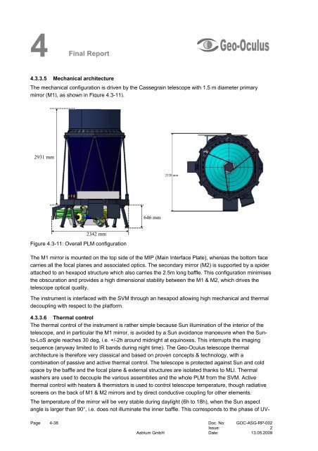
4.3.3.5 Mechanical architecture<br />
The mechanical configuration is driven by the Cassegrain telescope with 1.5 m diameter primary<br />
mirror (M1), as shown in Figure 4.3-11).<br />
2931 mm<br />
GEO-<br />
OCUL<br />
US-1<br />
2342 mm<br />
Figure 4.3-11: Overall PLM configuration<br />
646 mm<br />
2320 mm<br />
GEO-OCULUS-3<br />
The M1 mirror is mounted on the top side of the MIP (Main Interface Plate), whereas the bottom face<br />
carries all the focal planes and associated optics. The secondary mirror (M2) is supported by a spider<br />
attached to an hexapod structure which also carries the 2.5m long baffle. This configuration minimises<br />
the obscuration and provides a high dimensional stability between the M1 & M2, which drives the<br />
telescope optical quality.<br />
The instrument is interfaced with the SVM through an hexapod allowing high mechanical and thermal<br />
decoupling with respect to the platform.<br />
4.3.3.6 Thermal control<br />
The thermal control of the instrument is rather simple because Sun illumination of the interior of the<br />
telescope, and in particular the M1 mirror, is avoided by a Sun avoidance manoeuvre when the Sunto-LoS<br />
angle reaches 30 deg, i.e. +/-2h around midnight at equinoxes. This interrupts the imaging<br />
sequence (anyway limited to IR bands during night time). The Geo-Oculus telescope thermal<br />
architecture is therefore very classical and based on proven concepts & technology, with a<br />
combination of passive and active thermal control. The telescope is protected against Sun and cold<br />
space by the baffle and the focal plane & external structures are isolated thanks to MLI. Thermal<br />
washers are used to decouple the various assemblies and the whole PLM from the SVM. Active<br />
thermal control with heaters & thermistors is used to control telescope temperature, though radiative<br />
screens on the back of M1 & M2 mirrors and by direct conductive coupling for other elements.<br />
The temperature of the mirror will be very stable during daylight (6h to 18h), when the Sun aspect<br />
angle is larger than 90°, i.e. does not illuminate the inner baffle. This corresponds to the phase of UV-<br />
Page 4-38 Doc. No: GOC-ASG-RP-002<br />
Issue: 2<br />
Astrium GmbH Date: 13.05.2009


