Nimbus Compact M NET R32 Installation Manual UK

Create successful ePaper yourself
Turn your PDF publications into a flip-book with our unique Google optimized e-Paper software.
Hydraulic connections<br />
– discharges at high level: e.g. into a metal hopper and<br />
metal downpipe with the end of the discharge pipe<br />
clearly visible or onto a roof capable of withstanding<br />
high-temperature discharges of water and 3 m from<br />
any plastic guttering system that would collect such<br />
discharges.<br />
– The discharge would consist of high-temperature water<br />
and steam. Asphalt, roofing felt and non-metallic rainwater<br />
goods may be damaged by such discharges.<br />
Discharge pipe (D2) characteristics<br />
– The discharge pipe (D2) should be made of metal or<br />
other material with proven capacity to safely withstand<br />
the high temperatures of the water discharged (above<br />
95°), and be clearly and permanently marked to identify<br />
the product and its performance rating.<br />
– The discharge pipe (D2) should be at least one pipe-size<br />
larger than the nominal outlet size of the safety device,<br />
unless its total equivalent hydraulic resistance exceeds<br />
that of a 9 m-long straight pipe, i.e. for discharge pipes<br />
between 9 m and 18 m long, the equivalent resistance<br />
length should be at least two sizes larger than the nominal<br />
outlet size of the safety device; between 18 m and<br />
27 m, it should be at least 3 sizes larger, and so forth;<br />
bends must be taken into account when calculating<br />
the flow resistance.<br />
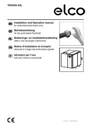
Typical discharge pipe arrangement<br />
1<br />
600 mm<br />
Maximum<br />
2<br />
300 mm<br />
Minimum<br />
4<br />
3<br />
5<br />
6<br />
Fig. 48<br />
1 Safety device (e.g. temperature relief valve)<br />
2 Metal discharge pipe (D1) from the temperature relief<br />
valve to the tundish<br />
3 Tundish<br />
4 Discharge pipe (D2) from the tundish, with continuous<br />
fall. (refer to “Connection of the discharge pipe (D2) to the<br />
tundish” in paragraph Safety device connection, the table<br />
below and the worked example)<br />
5 Fixed grating<br />
6 Trapped gully<br />
Discharge below fixed grating (see figure above).<br />
Sizing of copper discharge pipe (D2) for common temperature<br />
relief valve outlet sizes:<br />
Valve outlet size G1/2<br />
Minimum size of discharge pipe D1<br />
15 mm<br />
Minimum size of discharge pipe D2 from 22 mm<br />
tundish<br />
28 mm<br />
35 mm<br />
Maximum allowed resistance, expressed<br />
as the length of a straight pipe (i.e without<br />
elbows or bends)<br />
Resistance generated by each elbow or bend<br />
Up to 9 m<br />
Up to 18 m<br />
Up to 27 m<br />
0.8 m<br />
1.0 m<br />
1.4 m<br />
Worked example<br />
The example below is for a G½ temperature relief valve with a<br />
discharge pipe (D2) having 4 x 22 mm elbows and a 7 m length<br />
from the tundish to the point of discharge.<br />
– From the above table, the maximum allowed resistance<br />
for a straight length of 22 mm copper discharge pipe<br />
(D2) from a G½ temperature relief valve is: 9.0 m;<br />
– Subtract the resistance for 4 x 22 mm elbows at 0.8 m<br />
each = 3.2 m;<br />
– Therefore, the maximum allowed length amounts to 5.8<br />
m, which is less than the current length of 7 m, so calculate<br />
the next largest size;<br />
– Maximum allowed resistance for a straight length of 28<br />
mm copper discharge pipe (D2) from a G½ temperature<br />
relief valve is: 18 m;<br />
– Subtract the resistance for 4 x 28 mm elbows at 1.0 m<br />
each = 4 m;<br />
– Therefore, the maximum allowed length amounts to: 14 m;<br />
– Since the current length is 7 m, a 28 mm (D2) copper<br />
pipe will do.<br />
a<br />
The outlet from the temperature and pressure<br />
relief valve and expansion relief valve must not<br />
be used for any other purpose. The temperature<br />
and pressure relief valve must not be removed<br />
under any circumstances.<br />
4.2.5 Hydraulic connections<br />
Description<br />
Connection<br />
Type<br />
Connection<br />
Size<br />
T&P discharge Male G 1/2<br />
Safety inlet assembly:<br />
Safety valve Compression D 15<br />
Exp. vessel inlet Famale 3/4”<br />
inlet<br />
Cold mains water Compression 22 mm<br />
Cylinder outlet<br />
Compression 23 mm<br />
Expansion vessel Male 3/4 Gas<br />
a<br />
The installer must verify and provide evidence of<br />
conformity with respect to the following regulations:<br />
– The Building Regulations 2010 (S.I. 2010 No.<br />
2214), as amended;<br />
– The Water Supply (Water Fittings) Regulations<br />
1999 (S.I. 1999 No. 1148), as amended.<br />
30 / EN