
You also want an ePaper? Increase the reach of your titles
YUMPU automatically turns print PDFs into web optimized ePapers that Google loves.
Connector Termination/Basic Guidelines<br />
Cable Termination<br />
There are a variety of termination methods for cables. The termination<br />
method utilized depends basically on the system installed,<br />
type of cable used, and type of connector. Using the proper termination<br />
method allows for good mechanical and electrical integrity.<br />
No matter what type of termination you will be performing, the<br />
most important thing to remember is to use the proper tools and<br />
materials for your type of termination. For example, a crimp using<br />
pliers will work, but using a crimp tool and the proper die<br />
designed for your type of cable and connector is better. Using the<br />
proper solder type and the right temperature for solder type connections<br />
will ensure a lasting connection. We will review some<br />
basic termination techniques. This is just to provide some general<br />
guidelines. The termination method may vary somewhat based on<br />
system requirements and connector manufacturer design methods.<br />
Crimp Type Termination<br />
A crimp type connection allows for quick and simple installation<br />
while still maintaining a mechanical and electrical connection fairly<br />
close to a solder type termination. Solid or stranded wire can be<br />
used in this type of termination.<br />
Some of the key points to remember for a good clean connection<br />
are as follows: make sure to use the proper size connector for the<br />
type of cable you are using. Make sure all your cuts and stripping<br />
are clean. Avoid nicks as much as possible. Use the proper crimp<br />
tool; don’t try to improvise with pliers, etc.<br />
The most common crimp method involves two crimps. One is on<br />
the insulation for a stronger mechanical connection and one is on<br />
the conductor or shield for a good electrical connection. A crimp<br />
tool is designed specifically for this type of termination, for the<br />
type of connector you are using. This allows for good connections,<br />
both mechanical and electrical. Using pliers will allow a connection;<br />
however, it may not be a solid mechanical or electrical connection,<br />
and can cause the connector to eventually come loose,<br />
which can cause intermittent problems with the electrical signal.<br />
Technical Reference<br />
Splicing<br />
It is recommended to avoid splicing whenever possible. However,<br />
when splicing of cables becomes necessary, there are several methods<br />
to do this. Splicing can be as simple as twisting conductors<br />
together, soldering, and then taping. Splicing can also be more<br />
elaborate by using a variety of inline connectors and adapters. The<br />
method used is mainly based on the type of system used, the electrical<br />
signal characteristics, and type of cable used. A simple audio<br />
or intercom system can be spliced by just connecting the conductor<br />
together with the twist method. However, a CCTV or high speed<br />
data system will require inline connectors and adapters due to the<br />
construction of the cable as well as to maintain proper impedance,<br />
resistance, and capacitance characteristics for the cable run. If the<br />
location of the splice is outdoor or in underground environments,<br />
it is recommended that a waterproof splice kit be utilized.<br />
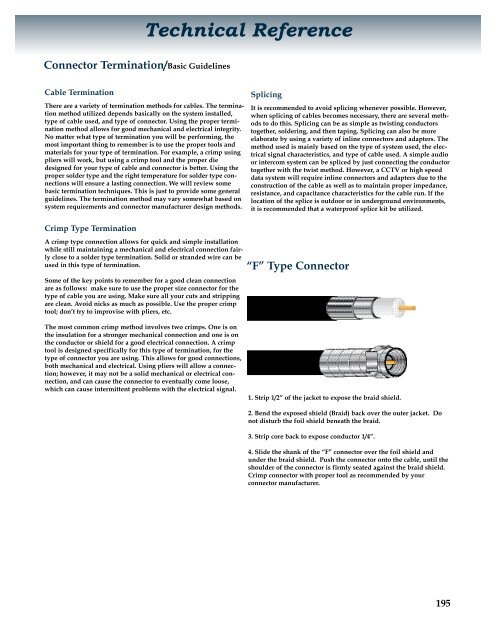
“F” Type Connector<br />
1. Strip 1/2” of the jacket to expose the braid shield.<br />
2. Bend the exposed shield (Braid) back over the outer jacket. Do<br />
not disturb the foil shield beneath the braid.<br />
3. Strip core back to expose conductor 1/4”.<br />
4. Slide the shank of the “F” connector over the foil shield and<br />
under the braid shield. Push the connector onto the cable, until the<br />
shoulder of the connector is firmly seated against the braid shield.<br />
Crimp connector with proper tool as recommended by your<br />
connector manufacturer.<br />
195