
Create successful ePaper yourself
Turn your PDF publications into a flip-book with our unique Google optimized e-Paper software.
Cable Termination Techniques<br />
Cable Termination<br />
There is a variety of termination methods for cable. The termination<br />
method utilized depends basically on the system installed,<br />
type of cable used and type of connector. Using the proper termination<br />
method allows for good mechanical and electrical integrity.<br />
No matter what type of termination you will be performing, the<br />
most important thing is to use the proper tools and materials for<br />
the type of termination. For example, a crimp using pliers will<br />
work, but using a crimp tool and the proper die designed for your<br />
type of cable and connector is better. Using the proper solder type<br />
and the right temperature for solder type connections will ensure a<br />
lasting connection. We will review four basic termination techniques.<br />
This is just to provide some general guidelines. The termination<br />
method may vary somewhat based on system requirements<br />
and connector manufacture design methods.<br />
Termination Types<br />
Solder Type<br />
A solder type connection allows for a strong, solid mechanical and<br />
electrical connection. Clean the connection well. For electrical circuits<br />
you must use a rosin type flux to clean all connections. Do<br />
not use acid flux that is commonly used for plumbing installation.<br />
The acid based flux will cause corrosion and inherently cause<br />
intermittent problems with the electrical signal. The choice of solder<br />
is also important. Using a solder standard 60/40 formula will<br />
meet the majority of your soldering needs. However, lead-free and<br />
high-grade silver solder is available for special applications. Also,<br />
use a soldering iron of the proper wattage. If the soldering iron is<br />
not hot enough, you may not be able heat the connection enough<br />
to get a good solder joint. This may cause what is known as a<br />
"cold" solder joint and can cause intermittent problems like opens<br />
to occur. However, if the soldering iron is too hot, you can cause<br />
damage to the components of the system near the connection. This<br />
can also cause the insulation to possibly melt causing the bare primaries<br />
to make contact with each other resulting in a short.<br />
Crimp Type<br />
A crimp type connection allows for quick and simple installation<br />
while still maintaining a mechanical and electrical connection fairly<br />
close to a solder type termination. Solid or stranded wire can be<br />
used in this type of termination.<br />
Some of the key points to remember for a good clean connection<br />
are as follows:<br />
1. Make sure you use the proper size connector for<br />
the type of cable you are using.<br />
2. Make sure all of your cuts and stripping are clean.<br />
3. Avoid nicks as much as possible.<br />
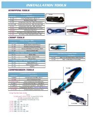
4. Use the proper crimp tool, don’t try to improvise<br />
with pliers, etc.<br />
The most common crimp method involves two crimps, one on the<br />
insulation for a stronger mechanical connection and one on the<br />
conductor or shield for a good electrical connection. A crimp tool is<br />
designed specifically for this type of termination for the type of<br />
connector you are using. This allows for good connections both<br />
mechanical and electrical. Using pliers will allow connection.<br />
However, it may not be a solid mechanical or electrical connection<br />
and can cause the connector to eventually come loose and intermittent<br />
problems with the electrical signal can occur.<br />
194<br />
Technical Reference<br />
Insulation Displacement<br />
This type of termination is usually used in punch down blocks,<br />
wall connectors, and in the back of patch panels. This type of termination<br />
eliminates the need for stripping the conductor<br />
insulation. As the conductor is pushed though the clip, the insulation<br />
is cut into and the metal clip contact makes contact with the<br />
wire.<br />
The best type of wire to use is a solid conductor. If you use a<br />
stranded conductor the force of the termination may allow the clip<br />
to cut some of the strands. Also, stranded wire will "crush" somewhat<br />
which will not allow for a solid connection. However, both<br />
types of conductors are used in various systems.<br />
The connection is made by using a punch down tool. Some patch<br />
panel manufacturers supply a termination cap that terminates several<br />
wires at once without the use of a tool. Some tools will allow<br />
use of different bits for use with various terminations. (i.e. 66<br />
block, 110 block, etc.). Just like the crimping type termination, it is<br />
important to use the correct bit for the type of termination you are<br />
doing.<br />
Direct Connection (Utility Block/ Screw Terminals)<br />
This type of termination has several names. Utility block, barrier<br />
strip, or screw terminals are just a few. This type of termination<br />
can use either solid or stranded conductors. It allows for easy termination<br />
as well as quick changing of wire in the future. The<br />
main point to remember about a screw connection is to strip back<br />
the insulation only to the amount of conductor that will wrap<br />
around the screw and to place the wire in the same direction as the<br />
screw turns when tightening. This will "pull" the wire in tighter as<br />
the screw tightens. If you wrap the wire around the screw opposing<br />
the tightening rotation of the screw, the wire will be pulled<br />
outward and will become unwrapped around the screw.<br />
Splicing<br />
It is recommended to avoid splicing whenever possible, however,<br />
when splicing of cables becomes necessary, there are several methods<br />
to do this. Splicing can be as simple as twisting conductors<br />
together, soldering and then taping. Splicing can also be more<br />
elaborate by using a variety of inline connectors and adapters. The<br />
method used is based on the type of system used, the electrical signal<br />
characteristics, and type of cable used. A simple audio or intercom<br />
system can be spliced by just connecting the conductor together<br />
with the twist method. However, a CCTV or high speed data<br />
system will require inline connectors and adapters due to the construction<br />
of the cable as well as to maintain proper impedance,<br />
resistance, and capacitance characteristics for the cable run. If the<br />
location of the splice is outdoor or in underground environments,<br />
it is recommended that a waterproof splice kit be utilized.