Concrete structures using fabric formwork
Concrete structures using fabric formwork
Concrete structures using fabric formwork

Create successful ePaper yourself
Turn your PDF publications into a flip-book with our unique Google optimized e-Paper software.
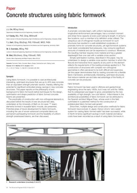
Paper<br />
<strong>Concrete</strong> <strong>structures</strong> <strong>using</strong> <strong>fabric</strong> <strong>formwork</strong><br />
J. J. Orr, MEng (Hons)<br />
Department of Architecture and Civil Engineering, University of Bath<br />
A. P. Darby, BSc, PhD, CEng, MIStructE<br />
Senior Lecturer in Structural Engineering, Dept of Architecture and Civil Engineering, University of Bath<br />
T. J. Ibell, CEng, BSc(Eng), PhD, FIStructE, MICE, FHEA<br />
Professor of Civil Engineering, Department of Architecture and Civil Engineering, University of Bath<br />
M. C. Evernden, MEng, PhD<br />
Lecturer in Structural Engineering, Department of Architecture and Civil Engineering, University of Bath<br />
M. Otlet, BSc(Hons), CEng, FIStructE, FSFE<br />
Director, Atkins Engineering and Major Projects, Atkins UK Ltd<br />
Keywords: Formwork, Fabric, <strong>Concrete</strong>, Beams, Design, Construction work, Testing, Loads<br />
Received: 06/10: Modified: 09/10; Accepted: 10/10<br />
© J. J. Orr, A. P. Darby, T. J. Ibell, M. C. Evernden & M. Otlet<br />
Synopsis<br />
Using <strong>fabric</strong> <strong>formwork</strong>, it is possible to cast architecturally<br />
interesting, optimised <strong>structures</strong> that use up to 40% less concrete<br />
than an equivalent strength prismatic section, thereby offering the<br />
potential for significant embodied energy savings in new concrete<br />
<strong>structures</strong>. This paper reports on the philosophy of and<br />
background to <strong>fabric</strong> <strong>formwork</strong> before techniques for the design,<br />
optimisation and shape prediction of <strong>fabric</strong> formed concrete<br />
beams are presented.<br />
The practicality of construction with non-orthogonal elements is<br />
discussed before the results of new structural test data,<br />
undertaken at the University of Bath on 4m span ‘T’ beam<br />
elements formed in reusable <strong>fabric</strong> moulds, are presented.<br />
Potential areas of future development for <strong>fabric</strong> <strong>formwork</strong>,<br />
including the use of woven advanced composite <strong>fabric</strong>s as<br />
permanent participating <strong>formwork</strong> and the feasibility of uniform<br />
strength prestressed beams, are then discussed.<br />
1 Research undertaken (courtesty C.A.S.T)<br />
20 The Structural Engineer 89 (8) 19 April 2011<br />
Introduction<br />
A prismatic concrete beam, with uniform transverse and<br />
longitudinal reinforcement percentages, has a constant moment<br />
and shear force capacity at every point along its length. In all but a<br />
few locations, such a member is by definition under utilised. The<br />
ubiquitous use of orthogonal moulds as <strong>formwork</strong> for such<br />
<strong>structures</strong> has resulted in a well-established vocabulary of<br />
prismatic forms for concrete <strong>structures</strong>, yet rigid <strong>formwork</strong> systems<br />
must resist considerable fluid pressures, may consume significant<br />
amounts of material and can be expensive to construct. Moreover,<br />
the resulting member requires more material and has a greater<br />
deadweight than one cast with a variable cross-section.<br />
Simple optimisation routines, described in this paper, may be<br />
undertaken to design a variable cross section member in which the<br />
flexural and transverse force capacity at any point on the element<br />
reflects the requirements of the loading envelope applied to it. The<br />
construction of <strong>structures</strong> with complex non-orthogonal<br />
geometries is often perceived to be both difficult and expensive,<br />
yet this paper demonstrates that by casting concrete into a flexible<br />
<strong>fabric</strong> membrane, architecturally interesting, optimised <strong>structures</strong><br />
that reduce material use and take real advantage of the fluidity of<br />
concrete can be produced.<br />
Fabric <strong>formwork</strong><br />
Fabric <strong>formwork</strong> has been used in offshore and geotechnical<br />
engineering since the early 1900s, but it was not until the 1960s<br />
that its widespread use began to grow, precipitated by the new<br />
availability of high strength, low cost <strong>fabric</strong>s1 . Initial interest in the<br />
architectural possibilities of <strong>fabric</strong> <strong>formwork</strong> can be attributed to<br />
the Spanish architect Miguel Fisac, whose work in this field<br />
culminated in a patented method for the construction of<br />
pre<strong>fabric</strong>ated <strong>fabric</strong> formed wall panels2 .<br />
Since then, multiple design and construction methods for <strong>fabric</strong><br />
<strong>formwork</strong> have evolved. In Japan, Kenzo Unno’s ‘zero-waste’<br />
system for casting <strong>fabric</strong> formed walls3 has been successful, while<br />
in North America significant savings in both material and labour<br />
costs have been recorded as a result of <strong>using</strong> <strong>fabric</strong> <strong>formwork</strong> in
2 Identical concrete cast in impermeable (Left) and permeable<br />
(Right) moulds<br />
the construction of columns and footings4 . Additional and ongoing<br />
research5 , led by Professor Mark West at the University of<br />
Manitoba’s Centre for Architectural Structures and Technology<br />
(C.A.S.T), has further considered the architectural possibilities of<br />
<strong>fabric</strong> <strong>formwork</strong> for beams and trusses, in addition to its use for<br />
shells, panels, columns and walls (Fig 1).<br />
Although it has a low embodied energy (of approximately<br />
0.90MJ/kg) 6 concrete is used in vast quantities. In 2008 world<br />
production of cement amounted to approximately 2.8 x 10⁹t7 , with<br />
its manufacture estimated to account for some 3% of all global<br />
CO2 emissions8 , providing further impetus for the design of<br />
optimised <strong>structures</strong>. <strong>Concrete</strong> volume savings in <strong>fabric</strong> formed<br />
beams, when compared to an equivalent strength prismatic<br />
member, of 40% have already been achieved9,10 , illustrating the<br />
potential for <strong>fabric</strong> <strong>formwork</strong> to reduce the embodied energy of<br />
new building <strong>structures</strong>.<br />
Yet <strong>fabric</strong> <strong>formwork</strong> does not simply facilitate reductions in<br />
material use. Forming concrete in a permeable mould allows air<br />
and water to escape from the <strong>formwork</strong> to provide a high quality<br />
surface finish that can be readily distinguished from an identical<br />
concrete cast against an impermeable mould, as illustrated in<br />
Fig 2. Reductions in water:cement ratio towards the external face<br />
of <strong>structures</strong> cast in permeable moulds have been widely<br />
reported 11 and provide a surface zone with improved hardness<br />
12, 13<br />
and reduced porosity 14 . The resulting concrete surface is more<br />
durable than one cast against impermeable <strong>formwork</strong>, with<br />
reductions in carbonation depth, chloride ingress and oxygenation<br />
reported in the literature 11 .<br />
For <strong>structures</strong> where the concrete grade specified is governed<br />
by durability rather than strength concerns, permeable <strong>formwork</strong><br />
offers significant opportunities for embodied energy savings. For<br />
example, a C20 concrete mix cast in permeable <strong>formwork</strong> has<br />
been found to have a lower carbonation depth after 11 months<br />
than a C50 mix cast in conventional <strong>formwork</strong> 12 , with such a<br />
reduction in concrete grade providing embodied energy savings of<br />
approximately 38% 6 – in addition to those savings already<br />
achieved simply by <strong>using</strong> <strong>fabric</strong> <strong>formwork</strong> to cast a structurally<br />
optimised form. Long term cost savings for concrete cast in<br />
permeable moulds have also been reported 15 and arise primarily<br />
from a reduction in maintenance and repair requirements.<br />
Allowing water, but not cement, to drain from the surface zone is<br />
imperative when permeable <strong>formwork</strong> is used, and while Price 11<br />
suggests a maximum pore size of 50μm be specified, much<br />
greater pore sizes have been successfully used by the authors.<br />
The high quality surface finish of concrete cast in <strong>fabric</strong> further<br />
encourages the use of exposed internal concrete surfaces, the<br />
consequence of which is two-fold: extraneous wall and ceiling<br />
coverings can be omitted and the now exposed thermal mass may<br />
properly be used in the provision of thermal comfort.<br />
Design<br />
Fabric<br />
The critical aspect of <strong>fabric</strong> <strong>formwork</strong> for determining shape and<br />
therefore aesthetic is the <strong>fabric</strong> itself. Although almost any woven<br />
<strong>fabric</strong> can be used as <strong>formwork</strong> for <strong>fabric</strong> cast concrete, tensile<br />
3 Anchorage <strong>using</strong> welded end plates<br />
strengths in both warp and weft directions must be sufficient to<br />
hold the wet concrete and a low creep modulus is desirable to limit<br />
<strong>formwork</strong> deformations during casting and curing. The available<br />
literature illustrates the use of a range of <strong>fabric</strong>s as <strong>formwork</strong>,<br />
including hessian 9 and geotextiles 16 , while more recent<br />
experimental work undertaken at the University of Bath has used a<br />
woven polyester <strong>fabric</strong> that has previously been utilised in the<br />
construction of underwater concrete <strong>structures</strong>.<br />
Once a suitable <strong>fabric</strong> has been chosen, a number of methods<br />
are available to determine the final shape of the fluid filled flexible<br />
membrane. Schmitz 17 used an iterative finite element based<br />
procedure to determine the form of <strong>fabric</strong> formed wall panels,<br />
while Veenendaal 18 implemented dynamic relaxation to predict the<br />
final shape of <strong>fabric</strong> formed beams. Empirical relationships<br />
determined by Bailiss 9 provide a less rigorous solution to the same<br />
problem, but have nevertheless been used successfully 10 , while<br />
Foster 19 used a simple step-wise based method to iteratively<br />
determine the shape of the concrete filled <strong>fabric</strong>. The complete<br />
solution, which requires the use of incomplete elliptic integrals, is<br />
given separately by Iosilevskii 20 .<br />
Reinforcement<br />
The reinforcement of variable section members adds some<br />
complexity to the construction process, yet fundamentally does<br />
not differ from an orthogonal structure. The provision of end<br />
anchorage has been seen in previous work10 to be a crucial<br />
consideration and both externally welded steel plates (Fig 3) and<br />
transversely welded internal bars have been used to achieve this.<br />
The provision of transverse reinforcement in a variable section<br />
member simply requires a varying link size, which is easily<br />
achieved but can add cost to the construction process. It is<br />
therefore imperative that any reinforcement specified be used to its<br />
full capacity.<br />
Analysis<br />
Structural design procedures for bending moment shaped beams,<br />
as developed at the University of Bath9,10 , are based on a sectional<br />
approach that aims to satisfy the bending and shear requirements<br />
of the beam at every point along its length. Where open web beam<br />
sections are desired (as discussed later), additional consideration<br />
must be given to the effects of Vierendeel action in the member<br />
(detailed elsewhere21 ).<br />
Flexural strength calculations are undertaken by first dividing the<br />
element into a number of equally spaced sections. By assuming<br />
that the longitudinal steel has yielded, the lever arm distance<br />
required to provide the required moment capacity at each section<br />
is quickly determined by equilibrium, Eq.(1) and Fig 4. This is<br />
repeated at each section along the length of the member to<br />
determine the optimised reinforcement layout for a given loading<br />
envelope.<br />
z =<br />
M<br />
F<br />
Rd<br />
bH ,<br />
...(1)<br />
Where z is the lever arm, M is the applied moment and F b,H the<br />
horizontal component of tension force on the section.<br />
The Structural Engineer 89 (8) 19 April 2011 21
4 Steel reinforced section flexural design basis<br />
5 Construction <strong>using</strong> <strong>fabric</strong><br />
7 Construction <strong>using</strong> the pinch mould<br />
For a beam with just one layer of reinforcement, the resulting<br />
effective depth is then proportional to the bending moment on the<br />
section. In such a situation, the vertical component of force in the<br />
bar will be equal to the applied shear force according to Eq.(2).<br />
This suggests that the inclined longitudinal bar may be used to<br />
provide both flexural and shear force capacity to the section.<br />
V =<br />
dM<br />
= F ,<br />
dx<br />
bv<br />
22 The Structural Engineer 89 (8) 19 April 2011<br />
...(2)<br />
Where V is the shear force, M is the applied moment, x is the<br />
position along the beam.<br />
However, utilising a longitudinal bar to provide vertical force<br />
capacity close to the supports in a simply supported beam<br />
requires the bar to be fully anchored at its ends. The use of<br />
external steel plates to provide such anchorage is an<br />
unsatisfactory solution as it introduces the potential for brittle<br />
failure, exposes the internal reinforcement to corrosion and<br />
increases construction complexity.<br />
Furthermore, for a structure subject to an envelope of loads the<br />
longitudinal reinforcement position will be determined by the<br />
maximum moment on each section. Where a structure is subject<br />
to both point and uniformly distributed loads, it is feasible that the<br />
maximum moment and maximum shear forces on a section will<br />
not originate from the same load case. In such a situation, a bar<br />
placed for moment capacity will then be incorrectly inclined to<br />
provide the desired vertical force, and thus transverse<br />
reinforcement will be required. However, an inclined bar still<br />
6 Construction <strong>using</strong> the keel mould<br />
provides some value of vertical force, which in design may be<br />
added to the shear resistance of the section to reduce its<br />
transverse reinforcement requirements (c.f. BS EN 1992-1-1 22<br />
(cl.6.2.1)).<br />
The assessment of shear capacity in <strong>fabric</strong> formed beams has<br />
previously been undertaken to BS 8110-123, yet the empirical<br />
‘concrete contribution’ of this method is not necessarily applicable<br />
to the design of variable section beams. This assertion is<br />
supported by the available test data 9, 10 , where shear has been<br />
seen to be the predominant failure mode.<br />
The variable angle truss model, as adopted by BS EN 1992-1-<br />
1 22 for sections with transverse reinforcement, considers only the<br />
capacity provided to the member by the reinforcement and thus<br />
avoids a reliance on empirical relationships to determine shear<br />
strength. A yet more attractive approach is found in compression<br />
field theory 24 , which allows the detailed analysis of any cross<br />
section shape to be undertaken. However, this approach is yet to<br />
be taken up by European code writing committees.<br />
Construction<br />
Fabric <strong>formwork</strong> provides a fundamentally simple construction<br />
method and an optimised beam can be formed <strong>using</strong> only a sheet<br />
of <strong>fabric</strong> and modest supporting frame, as illustrated in Fig 5. The<br />
<strong>fabric</strong>, as discussed above, is completely reusable, either for a<br />
repeat element or in an entirely new beam geometry.<br />
More stringent construction control is achieved through the use<br />
of the ‘keel mould’ for the production of pre-cast beams (Fig 6).
8 Pre-cast beam element<br />
10 Load cases and resulting shear and moment envelopes<br />
11 Test loads<br />
Here, the <strong>fabric</strong> is held vertically and secured to a ‘keel’ that has<br />
been pre-cut to the desired longitudinal beam profile. The <strong>fabric</strong> is<br />
then prestressed in two directions before being fixed in position.<br />
Prestressing the <strong>fabric</strong> prevents wrinkling during construction and<br />
minimises the volume of concrete in the tension zone.<br />
The ‘pinch mould’ (Fig 7) may alternatively be used to create<br />
pre-cast beams and trusses with more complex geometries. Using<br />
‘pinch points’ the sheets of <strong>fabric</strong> can be held together during<br />
casting, creating an opening in the resulting element. This is a<br />
potentially important consideration for the provision of building<br />
services, but requires more careful analysis in design, as previously<br />
discussed.<br />
Building services<br />
The aesthetic appeal of variable section members, coupled with a<br />
high quality surface finish and the additional advantages of<br />
exposed thermal mass make <strong>fabric</strong> <strong>formwork</strong> an ideal means by<br />
which architectural, structural and building service requirements<br />
can be integrated.<br />
Using the ‘pinch mould’ construction method, pre-cast variable<br />
section <strong>fabric</strong> formed beams can easily be created with voids in<br />
their mid-span zones (Fig 8). Such sections are rarely used in<br />
conventional reinforced concrete design, yet provide a simple<br />
method for the routing of service ductwork. However, such an<br />
arrangement may detract from the aesthetic appeal of exposed,<br />
<strong>fabric</strong> formed soffits and the provision of services through a raised<br />
floor may be more appropriate (Fig 9). Such an approach holds<br />
additional advantages for the circulation of air exposed to the<br />
concrete slab and allows the building to be easily adapted for<br />
future changes in use.<br />
9 Integration of building services<br />
Costs<br />
Whilst cost savings have been recorded in projects that made use<br />
of <strong>fabric</strong> <strong>formwork</strong> for the construction of columns and footings4 ,<br />
there is limited data available for the construction of more complex<br />
variable section elements. However, Pallet15 suggests that labour<br />
cost savings may be achieved as <strong>formwork</strong> stripping and work<br />
cycle times are improved when concrete is cast in <strong>fabric</strong>. Coupled<br />
with the aforementioned material use reductions, the economic<br />
advantage of <strong>fabric</strong> <strong>formwork</strong> is increasingly apparent.<br />
The construction of complex doubly curved concrete elements<br />
remains entirely feasible <strong>using</strong> well established computed<br />
numerically controlled (CNC) manufacturing processes to produce<br />
steel moulds for use as <strong>formwork</strong>. However, such an approach is<br />
both expensive and time consuming, and is suitable only where<br />
multiple identical elements are desired. Using <strong>fabric</strong> <strong>formwork</strong>, the<br />
creation of multiple ‘one-offs’ from a single sheet of <strong>fabric</strong> is<br />
entirely feasible, and can be undertaken anywhere in the world<br />
<strong>using</strong> simple construction techniques.<br />
Construction examples<br />
Whilst <strong>fabric</strong> <strong>formwork</strong> is increasingly used in North America in the<br />
construction of concrete columns and footings, there are far fewer<br />
examples of beam and slab construction. D’Aponte et al. 25 provide<br />
details of a number of small houses built <strong>using</strong> <strong>fabric</strong> <strong>formwork</strong>,<br />
and construction techniques for such <strong>structures</strong> are being refined<br />
in ongoing work at the Yestermorrow Design School, Vermont26 .<br />
T-beams<br />
Using the sectional analysis method described above, four 8m<br />
span <strong>fabric</strong> formed beams were recently designed at the University<br />
of Bath for use as precast elements in reinforced concrete frame<br />
The Structural Engineer 89 (8) 19 April 2011 23
12 T-beam general arrangement<br />
13 Keel mould table<br />
construction. These four elements were then scaled by 50% to<br />
facilitate structural testing, as described below.<br />
The beams were designed to the envelope of loads summarised<br />
in Fig 10, with additional dead load being applied to account for<br />
the cubic loss in concrete volume that occurs when elements are<br />
scaled linearly (all load partial safety factors are set to 1.00). The<br />
beams were tested in nine-point bending, with the point loads<br />
required to achieve the design moment envelope given in Fig 11<br />
(where a self-weight of 2.7kN/m is assumed).<br />
The four beams had identical external dimensions and varied<br />
only in the arrangement of their transverse and longitudinal<br />
reinforcement, as illustrated in Fig 12. Beams 1 and 2 were<br />
designed without considering the inclination of the longitudinal<br />
tensile steel, while Beams 3 and 4 considered the longitudinal steel<br />
to provide shear capacity at the supports. Beams 1 and 3 were<br />
transversely reinforced with minimum links according to BS EN<br />
1992-1-1 22 while Beams 2 and 4 were provided with links only<br />
where required according to an analysis <strong>using</strong> the modified<br />
compression field theory (cf. Collins et al. 24 ).<br />
A concrete strength of 40MPa and steel yield strength of<br />
500MPa was assumed for design purposes, with the actual<br />
concrete strengths and steel yield strengths at the time of testing<br />
being given in Table 1 and Table 2 respectively.<br />
Construction of the beams was undertaken <strong>using</strong> the keel<br />
mould, as described above and illustrated in Fig 13. A flat face at<br />
the supports was formed <strong>using</strong> a simple steel plate, pushed into<br />
the tensioned <strong>fabric</strong> and screwed to the plywood keel. The<br />
transverse and longitudinal steel reinforcement was bent and cut<br />
to the required shape before being tied together and placed into<br />
the mould, and a minimum cover to the longitudinal steel of 20mm<br />
was achieved <strong>using</strong> plastic spacers. The vertical sides of the top<br />
slab were cast against phenolic plywood that had first been<br />
treated with a release agent. The <strong>fabric</strong> was not treated in any way<br />
and all casts were made in the same mould <strong>using</strong> the same <strong>fabric</strong>,<br />
which was simply brushed down after use.<br />
Compared to an equivalent orthogonal section, and excluding<br />
24 The Structural Engineer 89 (8) 19 April 2011<br />
Test<br />
Face cast<br />
against timber<br />
14 T-beam formed in <strong>fabric</strong><br />
<strong>Concrete</strong><br />
strength at<br />
test (MPa)<br />
Maximum<br />
load, 2P1 +<br />
5P2, (kN)<br />
Table 1 Test result summary, Beams 1-4<br />
Midspan<br />
deflection at<br />
final load<br />
(mm)<br />
Failure mode<br />
Beam 1 42 114 89 Flexure<br />
Beam 2 39 119 86 Flexure<br />
Beam 3 44 115 89 Flexure<br />
Beam 4 33 133 89 Flexure<br />
0.2% proof<br />
stress<br />
3mm bar<br />
630MPa<br />
Yield<br />
stress<br />
Table 2 Measured steel properties at test<br />
10mm<br />
bar<br />
12mm bar<br />
566MPa 576MPa<br />
Face cast<br />
against <strong>fabric</strong><br />
the top slab, the optimised beam profile provides a concrete<br />
material saving of approximately 35%.<br />
The beams were demoulded 3 days after casting and allowed to<br />
cure for at least 20 days prior to testing. Beam 1 is shown in Fig<br />
14, where the disparity in concrete quality between that cast<br />
against plywood and that cast in <strong>fabric</strong> is again apparent.<br />
The beams were tested in the loading frame shown in Fig 15 to<br />
simulate the application of a uniformly distributed load, with the<br />
loads required to achieve the design moment envelope given<br />
previously in Fig 11. The beams were all tested in load control, with<br />
a constant ratio of P1:P2 of 1:2.44 applied up to the maximum<br />
load. The load-displacement response of each beam is<br />
summarised in Fig 16 and apposite test results are given in Table<br />
1. The design failure load of 107kN was marginally exceeded in all<br />
tests, with these relatively small increases accounted for by the<br />
actual yield stress of the bars being higher than that assumed for
15 Test set up<br />
16 Load-displacement test results, Beams 1-4<br />
design (Table 2) and the potential for small errors in the position of<br />
the longitudinal bars. In general the sectional method provides an<br />
accurate technique for determining the moment capacity of the<br />
variable section element.<br />
Beam 1 reached a maximum load of 114kN and after displaying<br />
some ductility the cantilever loads P1 were removed. Beam 1 was<br />
then loaded by the five central point loads at a constant load of<br />
approximately 86kN up to a midspan deflection of 85mm.<br />
Subsequently, load was applied at the mid-span only, with a<br />
constant load of 54kN carried by the section up to its maximum<br />
displacement of 90mm, as shown in Fig 16.<br />
Beams 2, 3 and 4 were tested in a similar manner, but after<br />
achieving ductility at their maximum load capacities (Fig 16) were<br />
loaded by the central point load only. Beam 4 achieved a slightly<br />
higher maximum load than the first three tests, but this increase is<br />
not considered to be significant.<br />
All beams displayed a ductile response, with yielding of the<br />
longitudinal steel leading eventually to compression failures in the<br />
top slab. Cracking of the sections was well distributed (Fig 17) and<br />
no shear failures were recorded, in contrast to tests previously<br />
undertaken at the University of Bath 9,10 in which shear was the<br />
predominant failure mode.<br />
The four beams described above displayed similar loaddeflection<br />
responses, with almost identical cracked and uncracked<br />
stiffnesses recorded. This demonstrates that the two shear design<br />
methods have relatively little effect on the overall member<br />
response, and the sectional design approach may thus be used<br />
with confidence in the design of optimised beam <strong>structures</strong>. In<br />
addition, the keel mould has now been successfully demonstrated<br />
as a feasible construction method for <strong>fabric</strong> formed concrete<br />
<strong>structures</strong>.<br />
The similar load capacities recorded between Beams 1-4 further<br />
suggests that transverse reinforcement design may be<br />
satisfactorily undertaken <strong>using</strong> either BS EN 1992-1-1 22 or the<br />
modified compression field theory. Whilst the beams described<br />
above were designed to fail in flexure, future work will be required<br />
to comprehensively assess the shear behaviour of variable section<br />
members. This will then allow more detailed design guidance to be<br />
provided.<br />
Serviceability<br />
The advantage of a prismatic beam is its constant stiffness prior to<br />
cracking. The variable section beam is inherently more flexible than<br />
its prismatic counterpart and thus the serviceability limit state may<br />
become a concern. For example, in the beams described above,<br />
applying a deflection limit of span/250 reduces the permissible<br />
load capacity by around 30%, as highlighted in Fig 16.<br />
Yet stringent deflection requirements can do little except add<br />
deadweight. Designing a structure to follow the loads applied to it,<br />
without adding unnecessary material is a more sensible -<br />
moreover, sustainable – approach to structural design. For those<br />
situations where stringent deflection criteria are truly important, the<br />
use of prestressed reinforcement provides an ideal solution. With<br />
<strong>fabric</strong> <strong>formwork</strong>, uniform strength prestressed beams (as<br />
described by Guyon27 , where the extreme fibres at every point on<br />
the beam are at their compressive or tensile stress limit, Fig18) are<br />
entirely feasible and display excellent behaviour at the serviceability<br />
limit state. With <strong>fabric</strong> <strong>formwork</strong>, optimised, materially efficient,<br />
aesthetically pleasing <strong>structures</strong> that minimise embodied energy<br />
and encourage the appropriate use of thermal mass are possible.<br />
The construction of such <strong>structures</strong> can now be undertaken <strong>using</strong><br />
a simple, reusable <strong>formwork</strong> system.<br />
The future<br />
The provision of reinforcement to a continually varying cross<br />
section has the potential to add significantly to construction time.<br />
A participating <strong>fabric</strong> system in which a composite <strong>fabric</strong><br />
incorporating carbon fibres acts as both <strong>formwork</strong> and<br />
reinforcement may therefore be advantageous in some situations.<br />
Improvements in three-dimensional weaving capabilities may allow<br />
designers to specify carbon fibre weave directions and densities at<br />
various points along the length of a beam based on the applied<br />
loads. The resulting <strong>formwork</strong> could then simply be filled with<br />
concrete to provide an optimised, composite reinforced structure<br />
The Structural Engineer 89 (8) 19 April 2011 25
17 Typical failure mode<br />
18 Uniform strength prestressed beams<br />
that minimises material use.<br />
There are, however, a number of technical hurdles to clear<br />
before such a method could be used in general construction. In<br />
addition to vandalism and fire protection, an adequate bond<br />
between concrete and reinforcement must be provided for the life<br />
of the structure and the existing architectural merit of <strong>fabric</strong> formed<br />
concrete <strong>structures</strong> must be maintained.<br />
Flexural elements are fundamentally inefficient and it is in the<br />
design of shell <strong>structures</strong> that real material savings may be found.<br />
Using a combination of inexpensive <strong>fabric</strong> as <strong>formwork</strong> and<br />
lightweight, durable, high strength carbon fibre sheets as<br />
reinforcement, medium span shell elements such as those already<br />
produced at C.A.S.T may become a realistic alternative to existing<br />
floor and roof systems, as illustrated in Fig 18.<br />
Conclusions<br />
The design of <strong>fabric</strong> formed concrete <strong>structures</strong> has, to date, been<br />
led primarily by architectural concerns. Work to provide more<br />
complete design guidance for these remarkable <strong>structures</strong> is now<br />
well underway. Fabric formed concrete beams offer significant<br />
advantages for designers, including reductions in material use,<br />
ease of construction and aesthetic appeal. Further advantages<br />
may be gained through the use of prestressed reinforcement,<br />
either steel or fibre reinforced polymers, where improvements in<br />
both serviceability and ultimate limit state behaviour can be<br />
obtained. Additional work is required to investigate the use of<br />
flexible fibre reinforced polymer <strong>fabric</strong>s and grids as both external<br />
participating reinforcement in beam <strong>structures</strong> and as internal<br />
reinforcement in thin-shell elements.<br />
By designing optimised concrete <strong>structures</strong>, significant savings<br />
in material use can be achieved, with concomitant reductions in<br />
both embodied carbon and construction cost. Fabric <strong>formwork</strong> not<br />
only provides a simple means by which such <strong>structures</strong> can be<br />
cast, but by allowing excess pore water to bleed from the surface<br />
of the concrete the resulting element is both durable and beautiful.<br />
Fabric <strong>formwork</strong> thus offers exciting opportunities for engineers<br />
and architects in the move towards a more sustainable<br />
construction industry.<br />
References<br />
1 Lamberton, B.A.: ‘Fabric forms for concrete’, Conc. int., December, 1989, p<br />
58-67<br />
2 Orr, J. J., Darby, A. P., Ibell, T. J.: ‘Innovative concrete <strong>structures</strong> <strong>using</strong> <strong>fabric</strong><br />
<strong>formwork</strong>’, SEMC 2010, Cape Town, South Africa, 4-8 September, 2010<br />
3 West, M.: ‘Kenzo Unno, Fabric Formed Walls’, Winnipeg, University of<br />
Manitoba, Available from<br />
http://www.umanitoba.ca/cast_building/assets/downloads/PDFS/Fabric_For<br />
mwork/Kenzo_Unno _Article.pdf.<br />
4 FabFormIndustries. Fastfoot Commercial Edging Video (online), 2010 [cited<br />
2010 27/05]; Available from: http://www.fabform.com/products/fastfoot/<br />
fastfoot_commercial_edging_video.html<br />
5 West, M., Araya, R.: ‘Fabric <strong>formwork</strong> for concrete <strong>structures</strong> and<br />
architecture’, Int. Conf. Textile Composites and Inflatable Structures,<br />
Barcelona, Spain, 5-7 October, 2009<br />
26 The Structural Engineer 89 (8) 19 April 2011<br />
19 Fabric cast columns supporting <strong>fabric</strong> formed<br />
shells (courtesy C.A.S.T)<br />
6 Hammond, G. P., Jones, C. I.: ‘Embodied energy and carbon in construction<br />
materials’, Proc. Instn Civil Engrs: Energy, 161 (2) p 87-98<br />
7 Van Oss, H. G.: ‘Mineral Commodity Summaries: Cement’, USGS, 2006<br />
8 CDIAC.: Fossil-Fuel CO2 emissions (online), 2005 [cited 2010 30/03];<br />
Available from: http://cdiac.esd.ornl.gov/trends/emis/meth_reg.html<br />
9 Bailiss, J.: ‘Fabric-formed concrete beams: Design and analysis’, MEng<br />
Thesis, Department of Architecture and Civil Engineering, Bath, University of<br />
Bath, 2006<br />
10 Garbett, J.: ‘Bone growth analogy for optimising flexibly fomed concrete<br />
beams’, MEng Thesis, Dept for Architecture and Civil Engineering, Bath,<br />
University of Bath, 2008<br />
11 Price, W. F.: ‘Controlled permeability <strong>formwork</strong>’. London, 2000<br />
12 Price, W .F. and Widdows, S. J.: ‘The effect of permeable <strong>formwork</strong> on the<br />
surface properties of concrete’, Magazine of Conc. Res., 43/155, 1991, p<br />
93-104<br />
13 Serafini, F. L.: ‘Corrosion protection of concrete <strong>using</strong> a controlled<br />
permeability <strong>formwork</strong> (CPF) system’, Corrosion and Corrosion Protection of<br />
Steel in <strong>Concrete</strong>, Sheffield, 1994<br />
14 Kasai, K., et al.: ‘Study on the evaluation of concrete quality prepared with<br />
permeable forms and plywood forms’, Trans. Jpn Conc. Inst, 10/1989, p<br />
59-66<br />
15 Pallet, P.: ‘Introduction to the <strong>formwork</strong>s scene’, <strong>Concrete</strong> Magazine. 1994,<br />
p 11-12<br />
16 West, M., Abdelgar, H. S., Gorski, J.: ‘State of the art report on <strong>fabric</strong><br />
<strong>formwork</strong>’, <strong>Concrete</strong>: Construction’s sustainable option, Sept 4-6, 2007<br />
17 Schmitz, R. P.: ‘Fabric formed concrete’, 17th Analysis and Computation<br />
speciality conference, 2006 Structures Congress, St. Louis, MO, May 18-20,<br />
2006<br />
18 Veenendaal, D.: ‘Evolutionary optimisation of <strong>fabric</strong> formed structural<br />
elements’, Thesis, Civil Engineering and Geosciences, Delft, University of<br />
Delft, 2008<br />
19 Foster, R.: ‘Form finding and analysis of <strong>fabric</strong> formed concrete beams’,<br />
MEng Thesis, Architecture and Civil Engineering, Bath, University of Bath,<br />
2010<br />
20 Iosilevskii, G.: ‘Shape of a soft container under hydrostatic load’, J. App.<br />
Mech., 77/1, 2010, p 3<br />
21 Vierendeel, A.: Longerons en treillis et longerons à arcades. Louvain, Trois<br />
Rois, 1897<br />
22 BS EN 1992-1-1, Eurocode 2: Design of concrete <strong>structures</strong> - Part 1-1:<br />
General rules and rules for buildings. 2004<br />
23 BS 8110-1, Structural use of concrete - Part 1: Code of practice for design<br />
and construction. 1997<br />
24 Collins, M. P., Mitchell, D., Bentz, E. C.: ‘Shear Design of <strong>Concrete</strong><br />
Structures’, The Structural Engineer, 86/10, 2008, p 32-39<br />
25 D’Aponte, E., Lawton, A. and Johnson, R. M.: ‘Fabric Formwork for<br />
Architectural <strong>Concrete</strong> Structures’, 1st Int. Conf. Conc. Techn., Tabriz, Iran,<br />
6-7 November, 2009<br />
26 Yestermorrow Design Build School (accessed, 01/08/10); Available from:<br />
http://www.yestermorrow.org/<br />
27 Guyon, Y.: Prestressed <strong>Concrete</strong>. London, Contractors Record and<br />
Municipal Engineering, 1953<br />
Acknowledgments<br />
The authors gratefully acknowledge the ongoing support of the<br />
Engineering and Physical Sciences Research Council (EPSRC) and<br />
Atkins UK Ltd, and wish to thank the technical staff in the<br />
Department of Architecture and Civil Engineering at the University<br />
of Bath for their assistance in preparing the tests described in this<br />
paper.