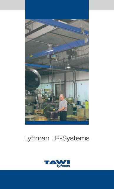
Lyftman LR-Systems
Lyftman LR-Systems
Lyftman LR-Systems

You also want an ePaper? Increase the reach of your titles
YUMPU automatically turns print PDFs into web optimized ePapers that Google loves.
<strong>Lyftman</strong> <strong>LR</strong>-<strong>Systems</strong><br />
<strong>Lyftman</strong>
2<br />
www.TAWI.com<br />
<strong>Lyftman</strong> <strong>LR</strong>-<strong>Systems</strong><br />
Produced from cold rolled, single piece high strength steel:<br />
The result is the reliable and cost effective <strong>LR</strong>120/170 profile.<br />
Self-adjusting joint concept: This design simplifies installation.<br />
Automatic powder-coating line: Ensures highest-quality resistance to corrosion<br />
and long service life (water based powder – a better environmental choice).<br />
Wide range: With the four basic track sizes an optimized combination is<br />
always guaranteed.<br />
Support: Span up to 8 meters between supports for ceiling structures with<br />
infrequent support points.<br />
Choice of material: Choose low gantry weight (aluminium) to reduce applied<br />
forces to the ceiling structure. Use aluminium girders for quick and smooth<br />
manual operation.<br />
Tricks: Use triple gantry solutions for light-weight installations with demands<br />
for a wider girder span.<br />
Swivelling suspensions: The swivelling suspensions are equipped with double<br />
ball couplings with bearing cups of Permaglide type to facilitate installation<br />
and improve operation.<br />
Dependability: The hoist trolley is equipped with double guide rollers for<br />
secure trolley movement in the track. The wheels have lubricated double<br />
sealed ball bearings for smooth, safe and quiet operation.<br />
Personal safety: The <strong>LR</strong>-System range of suspensions include a wide variety<br />
of solutions for maximum operational and personal safety. The rated capacity<br />
of a system is based on handling a load with the specified weight, plus the<br />
weight of the lifting equipment (estimated at max 15% of rated capacity) and<br />
with a hoist speed (impact estimated to max 25% of rated capacity).<br />
NEVER EXCEED the rated capacity!<br />
Personal safety: <strong>Lyftman</strong> <strong>LR</strong>-System is third-party certified by Det Norske<br />
Veritas in compliance with the EC Machine Directive.
m<br />
7<br />
6<br />
5<br />
4<br />
3<br />
2<br />
1<br />
86<br />
12<br />
49<br />
www.TAWI.com<br />
Load diagrams<br />
0<br />
0 10 20 30 40 50 60 70 80 90 100 110 120 130 kg<br />
170<br />
<strong>LR</strong>86 <strong>LR</strong>113<br />
Load diagrams: The SWL (Safe Working Load, x=kg)<br />
is increased when the distance between suspension points<br />
(y=m) is decreased. (Deflection max 1:350.)<br />
<strong>LR</strong>86 <strong>LR</strong>113 <strong>LR</strong>120 <strong>LR</strong>170<br />
Weight: 2,5 kg/m Weight: 5 kg/m Weight: 10 kg/m Weight: 20 kg/m<br />
U80x50x6<br />
19<br />
80<br />
<strong>LR</strong>120F1<br />
200<br />
113<br />
85<br />
KKR80x80x5<br />
15<br />
65<br />
19<br />
80<br />
125<br />
<strong>LR</strong>120F2<br />
<strong>LR</strong>170F1<br />
Weight: 18 kg/m Weight: 19 kg/m Weight: 28 kg/m Weight: 29 kg/m<br />
<strong>LR</strong>170F2<br />
Dimensions. The complete family of profiles is illustrated on page 2. Aluminiumprofiles <strong>LR</strong>86/<strong>LR</strong>113, steel profiles <strong>LR</strong>120/<strong>LR</strong>170,<br />
reinforced profiles <strong>LR</strong>120 F1/F2 and <strong>LR</strong>170 F1/F2.<br />
220<br />
120<br />
m<br />
9<br />
8<br />
7<br />
6<br />
5<br />
4<br />
3<br />
2<br />
1<br />
0<br />
0<br />
U80x50x6<br />
100<br />
200<br />
<strong>LR</strong>120 <strong>LR</strong>170 <strong>LR</strong>120F1 <strong>LR</strong>120F2 <strong>LR</strong>170F1 LF170F2<br />
19<br />
80<br />
25<br />
110<br />
500<br />
500<br />
500<br />
300<br />
400<br />
500<br />
600<br />
700<br />
800<br />
900<br />
170<br />
250<br />
KKR80x80x5<br />
25<br />
110<br />
25<br />
110<br />
1000<br />
1100<br />
1200<br />
1300<br />
1400<br />
1500<br />
1500<br />
1500<br />
1500<br />
3<br />
kg
4<br />
www.TAWI.com<br />
2<br />
Monorail solution in black-out blinds/<br />
window awnings industry.<br />
The steel industry uses <strong>Lyftman</strong> twin<br />
girder crane with motorized trolleys.
A combination of steel and<br />
aluminium profiles.<br />
www.TAWI.com<br />
<strong>LR</strong>-System in aluminium, end-of-line<br />
packaging, food industry.<br />
A monorail system used in the<br />
production of metal parts for<br />
the electronics- and automobile<br />
industries.<br />
5
6<br />
Monorail<br />
www.TAWI.com<br />
The monorail system is a cost effective choice with all the advantages<br />
of the <strong>Lyftman</strong> <strong>LR</strong>-System. The monorail serves a working area along<br />
a straight line with no demand for sideways transportation. The modular<br />
design of the <strong>LR</strong>-System allows for extensions and additions to create<br />
an x-y system anytime. Combine with <strong>LR</strong>-System curves for increased<br />
flexibility, page 14-15.<br />
A steel profile<br />
monorail system<br />
(<strong>LR</strong>120/170) with<br />
I-beam suspensions.<br />
The extension rods<br />
increase in length<br />
to compensate for<br />
the angle of the ceiling<br />
beam.<br />
An aluminium<br />
track with L-shaped<br />
suspension points<br />
installed into the side<br />
of the concrete beam.
Enquiry<br />
Company:<br />
Name:<br />
Tel:<br />
e-mail:<br />
Please send a copy of this page by fax<br />
to receive a complete quotation with<br />
technical specifications.<br />
Fax nr +46 300 189 90<br />
www.TAWI.com<br />
Enquiry, Monorail<br />
Requested c/c distance (N) mm:<br />
Requested max capacity (kg):<br />
Requested length of gantry (L) mm:<br />
Distance between floor and suspension point (P) mm:<br />
Type of carrying structure:<br />
Requested extension (R) mm:<br />
Requested minimum lifting level<br />
(from pallet, workbench etc in mm):<br />
Requested maximum lifting level (height in mm):<br />
Including hoist:<br />
Single/double lifting speed:<br />
Power: 3x400V 50 Hz / Other:<br />
Including VacuEasylift/VacuMove/Levalair:<br />
Monorail (mm)<br />
Profile<br />
type 40 kg 60 kg 80 kg 125 kg 250 kg 500 kg 1000 kg 1500 kg<br />
<strong>LR</strong>86 N max 3750 3200 2900 - - - - -<br />
M 80 80 80 - - - - -<br />
K L/1,5*70+G L/1,5*70+G L/1,5*70+G - - - - -<br />
B 80-300 80-300 80-300 - - - - -<br />
R 150-778 150-778 150-778 - - - - -<br />
<strong>LR</strong>113 N max 6000 5200 4700 3900 - - - -<br />
M 110 110 110 110 - - - -<br />
K L/1,5*70+G L/1,5*70+G L/1,5*70+G L/1,5*70+G - - - -<br />
B 150-500 150-500 150-500 150-500 - - - -<br />
R 200-828 200-828 200-828 200-828 - - - -<br />
<strong>LR</strong>120 N max 8000 8000 7000 6100 4700 2300 - -<br />
M 105 105 105 105 105 220 - -<br />
K L/1,5*70+G L/1,5*70+G L/1,5*70+G L/1,5*70+G L/1,5*70+G L/1,5*70+G - -<br />
B 120-3950 120-3950 120-3950 120-3400 120-1300 120-500 - -<br />
R 285-883 285-883 285-883 285-883 285-883 285-883 - -<br />
<strong>LR</strong>170 N max - - 8000 8000 8000 6300 3300 2300<br />
M - - 110 110 110 110 230 230<br />
K - - L/1,5*70+G L/1,5*70+G L/1,5*70+G L/1,5*70+G L/1,5*70+G L/1,5*70+G<br />
B - - 150-3950 150-3950 150-2500 150-900 150-400 150-250<br />
R - - 285-883 285-883 285-883 285-883 285-883 285-883<br />
The indicated values for “R” are standard values. Other dimensions are available on request.<br />
7
Gantry<br />
8<br />
www.TAWI.com<br />
Single girder cranes<br />
The single girder crane system is the most popular type of industrial<br />
installation. This system covers a rectangular (x-y) working area.<br />
Multiple girders are typically used when the system covers more than<br />
one working station. With multiple girders the complete system can<br />
either be dimensioned to handle the heaviest weight, or buffers/stops<br />
can be used to separate the working areas.<br />
A typical solution for production lines with<br />
several working stations. A separate girder<br />
is installed for each station. There is no<br />
limit to the length of this gantry, 50–60<br />
metres is common.<br />
Working area<br />
Girder<br />
The basic overhead x-y crane system.<br />
Competitive pricing, fast deliveries,<br />
high quality and easy installation is<br />
the secret behind this popular solution.<br />
Working area
Enquiry<br />
Company:<br />
Name:<br />
Tel:<br />
e-mail:<br />
Please send a copy of this page by fax<br />
to receive a complete quotation with<br />
technical specifications.<br />
Fax nr +46 300 189 90<br />
www.TAWI.com<br />
Enquiry, Single girder cranes<br />
Requested c/c distance (N) mm:<br />
Requested max capacity (kg):<br />
Requested length of gantry (L) mm:<br />
Requested length of girder (A) mm:<br />
Distance between floor and suspension point (P) mm:<br />
Type of carrying structure:<br />
Requested extension (R) mm:<br />
Requested minimum lifting level<br />
(from pallet, workbench etc in mm):<br />
Requested maximum lifting level (height in mm):<br />
Number of girders:<br />
Including hoist:<br />
Single/double lifting speed:<br />
Power: 3x400V 50 Hz / Other:<br />
Including VacuEasylift/VacuMove/Levalair:<br />
Single girder cranes (mm)<br />
Profile<br />
type 40 kg 60 kg 80 kg 125 kg 250 kg 500 kg 1000 kg 1500 kg<br />
<strong>LR</strong>86 N max 3750 3200 2900 - - - - -<br />
M 80 80 80 - - - - -<br />
K L/1,5*70+G L/1,5*70+G L/1,5*70+G - - - - -<br />
A max 4000 3400 3000 - - - - -<br />
R 150-778 150-778 150-778 - - - - -<br />
J 150 150 150 - - - - -<br />
G 80 80 80 - - - - -<br />
F L/1,5*70+G L/1,5*70+G L/1,5*70+G - - - - -<br />
B 80-300 80-300 80-300 - - - - -<br />
<strong>LR</strong>113 N max 6000 5200 4700 3900 - - - -<br />
M 110 110 110 110 - - - -<br />
K L/1,5*70+G L/1,5*70+G L/1,5*70+G L/1,5*70+G - - - -<br />
A max 6000 6000 5300 4400 - - - -<br />
R 200-828 200-828 200-828 200-828 - - - -<br />
J 190 190 190 190 - - - -<br />
G 110 110 110 110 - - - -<br />
F L/1,5*70+G L/1,5*70+G L/1,5*70+G L/1,5*70+G - - - -<br />
B 150-500 150-500 150-500 150-500 - - - -<br />
<strong>LR</strong>120 N max 8000 8000 7000 6100 4700 2300 - -<br />
M 105 105 105 105 105 220 - -<br />
K L/1,5*70+G L/1,5*70+G L/1,5*70+G L/1,5*70+G L/1,5*70+G L/1,5*70+G - -<br />
A max 8000 8000 8000 7100 5300 3700 - -<br />
R 285-883 285-883 285-883 285-883 285-883 285-883 - -<br />
J 250 250 250 250 250 250 - -<br />
G 105 105 105 105 105 220 - -<br />
F L/1,5*70+G L/1,5*70+G L/1,5*70+G L/1,5*70+G L/1,5*70+G L/1,5*70+G - -<br />
B 120-3950 120-3950 120-3950 120-3400 120-1300 120-500 - -<br />
<strong>LR</strong>170 N max - - 8000 8000 8000 6300 3300 2300<br />
M - - 110 110 110 110 230 230<br />
K - - L/1,5*70+G L/1,5*70+G L/1,5*70+G L/1,5*70+G L/1,5*70+G L/1,5*70+G<br />
A max - - 8000 8000 8000 7100 3900 2700<br />
R - - 285-883 285-883 285-883 285-883 285-883 285-883<br />
J - - 250 250 250 250 250 250<br />
G - - 110 110 110 110 230 230<br />
F - - L/1,5*70+G L/1,5*70+G L/1,5*70+G L/1,5*70+G L/1,5*70+G L/1,5*70+G<br />
B - - 150-3950 150-3950 150-2500 150-900 150-400 150-250<br />
The indicated values for “R” are standard values. Other dimensions are available on request.<br />
9
10<br />
Twin girder cranes<br />
Increase the performance of your twin girder crane<br />
system with motorized trolleys. When handling loads<br />
up to 1500 kg a safe and smooth operation is easy<br />
to achieve with <strong>Lyftman</strong> <strong>LR</strong>-<strong>Systems</strong>.<br />
www.TAWI.com<br />
A twin girder crane system is the heavy-duty choice. The twin girders<br />
are welded together in a triangular construction to stabilize operation<br />
when handling loads up to 1500 kg. The twin girder crane is optionally<br />
equipped with motorized trolleys to automate the travelling motion<br />
of the girder and/or hoist. The two-speed motorized trolleys can be<br />
equipped with a frequence converter for more options.<br />
<strong>Lyftman</strong> motorized trolleys.<br />
Working area<br />
Working area
Enquiry<br />
Company:<br />
Name:<br />
Tel:<br />
e-mail:<br />
Please send a copy of this page by fax<br />
to receive a complete quotation with<br />
technical specifications.<br />
Fax nr +46 300 189 90<br />
www.TAWI.com<br />
Enquiry, twin girder cranes<br />
Requested c/c distance (N) mm:<br />
Requested max capacity (kg):<br />
Requested length of gantry (L) mm:<br />
Requested length of girder (A) mm:<br />
Distance between floor and suspension point (P) mm:<br />
Type of carrying structure:<br />
Requested extension (R) mm:<br />
Requested minimum lifting level<br />
(from pallet, workbench etc in mm):<br />
Requested maximum lifting level (height in mm):<br />
Number of cranes:<br />
Including hoist:<br />
Single/double lifting speed:<br />
Power: 3x400V 50 Hz / Other:<br />
Powered crane motion:<br />
Powered hoist motion:<br />
Twin girder cranes (mm)<br />
Profile<br />
type 125 kg 250 kg 500 kg 1000 kg 1500 kg<br />
<strong>LR</strong>120 N max 6100 4400 2400 - -<br />
M 400 400 400 - -<br />
K L/1,5*70+G L/1,5*70+G L/1,5*70+G - -<br />
A max 8000 7100 5200 - -<br />
R 285-883 285-883 285-883 - -<br />
J 250 250 250 - -<br />
G 105 105 220 - -<br />
F L/1,5*70+G L/1,5*70+G L/1,5*70+G - -<br />
B 120-2500 120-1500 120-500 - -<br />
<strong>LR</strong>170 N max 8000 8000 6200 3300 2300<br />
M 460 460 460 460 460<br />
K L/1,5*70+G L/1,5*70+G L/1,5*70+G L/1,5*70+G L/1,5*70+G<br />
A max 8000 8000 8000 7400 6100<br />
R 285-883 285-883 285-883 285-883 285-883<br />
J 405-1060 405-1060 405-1060 405-1060 405-1060<br />
G 310 310 310 310 310<br />
F L/1,5*70+G L/1,5*70+G L/1,5*70+G L/1,5*70+G L/1,5*70+G<br />
B 150-3950 150-2400 150-900 150-350 150-200<br />
The indicated values for “R” are standard values. Other dimensions are available on request.<br />
11
Low built <strong>Systems</strong> /<br />
Floor mounted<br />
constructions<br />
Saving important space – the low built<br />
construction.<br />
www.TAWI.com<br />
The low built crane system is a compact solution, designed to allow<br />
a maximum possible vertical hook stroke in areas with low head room.<br />
The special low built construction holds the girder and gantry at the<br />
same level. The low built system can be suspended from free-standing<br />
constructions, as illustrated below, or from the ceiling. A free-standing<br />
construction is flexible and easy to install.<br />
<strong>LR</strong>86/113 aluminium profile system in a low built system.<br />
SWL up to 125 kg. Suitable for light weight goods handling<br />
in all types of production.<br />
Working<br />
area<br />
12<br />
www.tawi.se<br />
<strong>LR</strong>120/170 steel profile system in a lowbuilt<br />
system. SWL up to 1500 kg with reinforced<br />
profiles. The freestanding, portal suspending<br />
construction is an alternative to ceiling and<br />
wall suspension.<br />
Total width<br />
Working<br />
area<br />
Total height
www.TAWI.com<br />
Enquiry, Low built <strong>Systems</strong> / Floor mounted constructions<br />
Enquiry<br />
Company:<br />
Name:<br />
Tel:<br />
e-mail:<br />
Please send a copy of this page by fax<br />
to receive a complete quotation with<br />
technical specifications.<br />
Fax nr +46 300 189 90<br />
Requested c/c distance (N) mm:<br />
Requested max capacity (kg):<br />
Requested length of gantry (L) mm:<br />
Requested length of girder (A) mm:<br />
Total height mm:<br />
Total width mm:<br />
Type of carrying structure: or<br />
Floor mounted construction?<br />
Requested minimum lifting level<br />
(from pallet, workbench etc in mm):<br />
Requested maximum lifting level (height in mm):<br />
Number of girders:<br />
Including hoist:<br />
Single/double lifting speed:<br />
Power: 3x400V 50 Hz / Other:<br />
Including VacuEasylift/VacuMove/Levalair:<br />
Lowbuilt single girder cranes (mm)<br />
Profile<br />
type 40 kg 60 kg 80 kg 125 kg 250 kg 500 kg 1000 kg 1500 kg<br />
<strong>LR</strong>86 N max 3900 3400 3100 - - - - -<br />
M 280 280 280 - - - - -<br />
K L/1,5*70+G L/1,5*70+G L/1,5*70+G - - - - -<br />
C max 4000 3400 3000 - - - - -<br />
R 150-778 150-778 150-778 - - - - -<br />
G 140 140 140 - - - - -<br />
F L/1,5*70+G L/1,5*70+G L/1,5*70+G - - - - -<br />
B 80-300 80-300 80-300 - - - - -<br />
<strong>LR</strong>113 N max 6000 5300 4800 4000 - - - -<br />
M 285 285 285 285 - - - -<br />
K L/1,5*70+G L/1,5*70+G L/1,5*70+G L/1,5*70+G - - - -<br />
C max 6000 6000 5300 4400 - - - -<br />
R 200-828 200-828 200-828 200-828 - - - -<br />
G 170 170 170 170 - - - -<br />
F L/1,5*70+G L/1,5*70+G L/1,5*70+G L/1,5*70+G - - - -<br />
B 150-500 150-500 150-500 150-500 - - - -<br />
<strong>LR</strong>120 N max 8000 8000 7100 6100 4700 2300 - -<br />
M 205 205 205 205 205 205 - -<br />
K L/1,5*70+G L/1,5*70+G L/1,5*70+G L/1,5*70+G L/1,5*70+G L/1,5*70+G - -<br />
C max 6000 6000 6000 6000 5300 3700 - -<br />
R 285-883 285-883 285-883 285-883 285-883 285-883 - -<br />
G 105 105 105 105 105 220 - -<br />
F L/1,5*70+G L/1,5*70+G L/1,5*70+G L/1,5*70+G L/1,5*70+G L/1,5*70+G - -<br />
B 120-3950 120-3950 120-3950 120-3400 120-1300 120-500 - -<br />
<strong>LR</strong>170 N max - - 8000 8000 8000 6300 3300 2300<br />
M - - 110 110 110 110 230 230<br />
K - - L/1,5*70+G L/1,5*70+G L/1,5*70+G L/1,5*70+G L/1,5*70+G L/1,5*70+G<br />
C max - - 6000 6000 6000 6000 3900 2700<br />
R - - 285-883 285-883 285-883 285-883 285-883 285-883<br />
G - - 110 110 110 110 230 230<br />
F - - L/1,5*70+G L/1,5*70+G L/1,5*70+G L/1,5*70+G L/1,5*70+G L/1,5*70+G<br />
B - - 150-3950 150-3950 150-2500 150-900 150-400 150-250<br />
The indicated values for “R” are standard values. Other dimensions are available on request.<br />
13
14<br />
Curves<br />
www.TAWI.com<br />
Curves are a natural step towards the optimal overhead system. With<br />
45 degree angular modules in combination with the family of profiles and<br />
the flexible range of suspensions we can offer a perfect system, every time.<br />
Curves are used to follow a production line through the manufacturing<br />
process and to create a more flexible monorail where single girder cranes<br />
are out of the questions due to obstructions.<br />
Curves (mm)<br />
With our 45 degree modules you can create an overhead<br />
system that follows your production all the way from primary<br />
produce to packing stations.<br />
Profile type r= H= Max Load (kg) I=<br />
<strong>LR</strong>86 800 45° 85 200<br />
<strong>LR</strong>113 800 45° 125 200<br />
<strong>LR</strong>120 800 45° 350 200<br />
P<strong>LR</strong>170 1500 45° 750 200<br />
For info on values “M”, “N”, “K” and “R” se Monorails, page 7.
Enquiry<br />
Company:<br />
Name:<br />
Tel:<br />
e-mail:<br />
Please send a copy of this page by fax<br />
to receive a complete quotation with<br />
technical specifications.<br />
Fax nr +46 300 189 90<br />
www.TAWI.com<br />
Enquiry, curves<br />
Requested c/c distance (N) mm:<br />
Requested max capacity (kg):<br />
Requested length of gantry (L) mm:<br />
Number of curves:<br />
Distance between floor and suspension point (P) mm:<br />
Type of carrying structure:<br />
Requested (R) mm:<br />
Requested minimum lifting level<br />
(from pallet, workbench etc in mm):<br />
Requested maximum lifting level (height in mm):<br />
Including hoist:<br />
Single/double lifting speed:<br />
Power: 3x400V 50 Hz / Other:<br />
Including VacuEasylift/VacuMove/Levalair:<br />
Working area<br />
15
The wall mounted jib crane includes arm and<br />
bracket, 1 pce trolley for lifting equipment, 3 pcs<br />
trolley for air tube with leather strap, end stop, load<br />
signs and 4 pcs bolts.<br />
16<br />
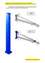
<strong>LR</strong>AV wall jib cranes<br />
<strong>LR</strong>AP column jib cranes<br />
Arm in aluminium<br />
<strong>LR</strong>86 up to 80 kg<br />
Jib arm <strong>LR</strong>AV (mm)<br />
Arm in aluminium<br />
<strong>LR</strong>113 up to 125 kg<br />
Arm Weight<br />
Type Load,kg A C D E F L N profile (kg)<br />
<strong>LR</strong>AV2/80 40-80 2000 577 507 110 150 14 3035 <strong>LR</strong>86 15<br />
<strong>LR</strong>AV3/80 40-80 3000 577 507 110 150 14 3035 <strong>LR</strong>86 19<br />
<strong>LR</strong>AV4/40 40 4000 577 507 110 150 14 3035 <strong>LR</strong>86 22<br />
<strong>LR</strong>AV5/40 40 5000 577 507 110 150 14 3035 <strong>LR</strong>86 27<br />
<strong>LR</strong>AV4/60 60 4000 577 507 110 150 14 3035 <strong>LR</strong>86 23<br />
<strong>LR</strong>AV6/40 40 6000 860 800 150 200 18 3050 <strong>LR</strong>113 65<br />
<strong>LR</strong>AV4/80 80 4000 860 800 150 200 18 3050 <strong>LR</strong>113 55<br />
<strong>LR</strong>AV5/80 80 5000 860 800 150 200 18 3050 <strong>LR</strong>113 60<br />
<strong>LR</strong>AV2/125 125 2000 860 800 150 200 18 3050 <strong>LR</strong>113 45<br />
<strong>LR</strong>AV3/125 125 3000 860 800 150 200 18 3050 <strong>LR</strong>113 50<br />
Column for <strong>LR</strong>AV (mm)<br />
Type For jib arm* B J H J K M<br />
Weight<br />
(kg)<br />
LPM15361 <strong>LR</strong>AV2/80 3610 250 200 20 18 M12 95<br />
LPM15361 <strong>LR</strong>AV3/80 3610 250 200 20 18 M12 95<br />
LPM15361 <strong>LR</strong>AV3-4/40 3610 250 200 20 18 M12 95<br />
LPM15361 <strong>LR</strong>AV5/40 3610 250 200 20 18 M12 95<br />
LPM15361 <strong>LR</strong>AV4/60 3610 250 200 20 18 M12 95<br />
LPM20386 <strong>LR</strong>AV6/40 3860 300 250 20 24 M16 145<br />
LPM20386 <strong>LR</strong>AV4/80 3860 300 250 20 24 M16 145<br />
LPM20386 <strong>LR</strong>AV5/80 3860 300 250 20 24 M16 145<br />
LPM20386 <strong>LR</strong>AV2/125 3860 300 250 20 24 M16 145<br />
LPM20386 <strong>LR</strong>AV3/125 3860 300 250 20 24 M16 145<br />
* The jib crane includes arm and bracket, 1 pce trolley for lifting equipment,<br />
3 pcs trolley for air tube with leather strap, end stop, load signs and 4 pcs bolts.<br />
www.TAWI.com<br />
Manual jib cranes up to 125 kg<br />
<strong>LR</strong>AVL low-built wall jib cranes<br />
<strong>LR</strong>APL low-built column jib cranes<br />
Low-built arm in aluminium<br />
<strong>LR</strong>86 up to 40 kg<br />
Jib arm <strong>LR</strong>AVL (mm)<br />
Type Load, kg A C D E F L N<br />
Arm<br />
profile<br />
<strong>LR</strong>AV2/40L 40 2000 300 232 110 150 Ø14 B-300 <strong>LR</strong>86<br />
<strong>LR</strong>AV3/40L 40 3000 300 232 110 150 Ø14 B-300 <strong>LR</strong>86<br />
<strong>LR</strong>AV3,5/40L 40 3500 300 232 110 150 Ø14 B-300 <strong>LR</strong>86<br />
Column for <strong>LR</strong>AVL (mm)<br />
Type For jib arm* B G H J K M<br />
LPM15361L <strong>LR</strong>AV2/40L Custom made 250 200 20 Ø18 M12<br />
LPM15361L <strong>LR</strong>AV3/40L Custom made 250 200 20 Ø18 M12<br />
LPM15361L <strong>LR</strong>AV3,5/40L Custom made 250 200 20 Ø18 M12<br />
* The jib crane includes arm and bracket, 1 pce trolley for lifting equipment,<br />
3 pcs trolley for air tube with leather strap, end stop, load signs and 4 pcs bolts.<br />
A twin brace is automatically included in<br />
the installation when certain rated SWL’s<br />
are exceeded.
UVM low-built wall jib cranes<br />
UPM low-built column jib cranes<br />
www.TAWI.com<br />
<strong>LR</strong>AVU low-built wall jib cranes<br />
<strong>LR</strong>APU low-built column jib cranes<br />
Low-built arm in steel <strong>LR</strong>120 up to 80 kg Low-built arm in aluminium <strong>LR</strong>113 up to 25 kg<br />
Project planner:<br />
A manually operated jib crane is most effective<br />
when the outer part (2/3) of the arm is used!<br />
Do not over-dimension. No need to push around<br />
excessive weight.<br />
Jib arm UVM (mm) Jib arm <strong>LR</strong>AVU (mm)<br />
Type Load, kg A C D E F L N<br />
Arm<br />
profile<br />
UVM2/80 80 2000 521 416 150 200 Ø18 B-185 <strong>LR</strong>120<br />
UVM3/80 80 3000 521 416 150 200 Ø18 B-185 <strong>LR</strong>120<br />
UVM4/60 60 4000 521 416 150 200 Ø18 B-185 <strong>LR</strong>120<br />
Column for UVM (mm)<br />
Type For jib arm* B G H J K M<br />
LPM15361U UVM2/80 Custom made 300 250 20 Ø24 M16<br />
LPM15361U UVM3/80 Custom made 300 250 20 Ø24 M16<br />
LPM15361U UVM4/60 Custom made 300 250 20 Ø24 M16<br />
* The jib crane includes arm and bracket, 1 pce trolley for lifting equipment,<br />
3 pcs trolley for air tube with leather strap, end stop, load signs and 4 pcs bolts.<br />
If the area to be covered is large, consider a crane<br />
system instead of a jib crane.<br />
The rated capacity of a system is based on<br />
handling a load with the specified weight, plus the<br />
weight of the lifting equipment (estimated at max<br />
15% of rated capacity) and with a hoist speed<br />
(impact estimated to max 25% of rated capacity).<br />
NEVER EXCEED the rated capacity!<br />
Type Load, kg A C D E F L N<br />
Arm<br />
profile<br />
<strong>LR</strong>AVU2/25 25 2000 441 341 110 150 Ø14 B-165 <strong>LR</strong>113<br />
<strong>LR</strong>AVU3/25 25 3000 441 341 110 150 Ø14 B-165 <strong>LR</strong>113<br />
Column for <strong>LR</strong>AVU (mm)<br />
Type For jib arm* B G H J K M<br />
LPM15361A <strong>LR</strong>AVU2/25 Custom made 250 200 20 Ø18 M12<br />
LPM15361A <strong>LR</strong>AVU3/25 Custom made 250 200 20 Ø18 M12<br />
* The jib crane includes arm and bracket, 1 pce trolley for lifting equipment,<br />
3 pcs trolley for air tube with leather strap, end stop, load signs and 4 pcs bolts.<br />
17
Max capacity<br />
18<br />
Nominel length<br />
Arm S<br />
Actual length<br />
Consol type<br />
www.TAWI.com<br />
Manual column jib cranes up to 1000 kg<br />
Total height<br />
Type<br />
Column jib crane, radius of action 300°<br />
Under arm height<br />
Column jib cranes <strong>LR</strong>P, C-profile<br />
Overall dimensions (mm)<br />
(kg) (m) (mm) H (m) (mm) G L M N ∆ (kg) (kg)<br />
63 4 4056 A 3 <strong>LR</strong>P4/63 2496 220 34 125 585 12 124 18<br />
5 5056 A 3 <strong>LR</strong>P5/63 2496 220 34 125 645 12 137 18<br />
6 6056 B 3 <strong>LR</strong>P6/63 2496 255 34 125 730 12 185 28<br />
7 7056 B 3 <strong>LR</strong>P7/63 2496 255 34 125 790 12 195 28<br />
125 2 2056 A 3 <strong>LR</strong>P2/125 2496 220 34 125 525 12 98 18<br />
3 3056 A 3 <strong>LR</strong>P3/125 2496 220 34 125 585 12 111 18<br />
4 4056 B 3 <strong>LR</strong>P4/125 2496 255 34 125 610 12 156 28<br />
5 5056 B 3 <strong>LR</strong>P5/125 2496 255 34 125 670 12 169 28<br />
6 6066 C 3.5 <strong>LR</strong>P6/125 2738 310 34 125 800 17 253 34<br />
7 7066 C 3.5 <strong>LR</strong>P7/125 2738 310 34 125 860 17 268 34<br />
250 2 2056 B 3 <strong>LR</strong>P2/250 2496 255 34 125 550 12 130 28<br />
3 3056 B 3 <strong>LR</strong>P3/250 2496 255 34 125 610 12 143 28<br />
4 4066 C 3.5 <strong>LR</strong>P4/250 2738 310 34 125 680 17 223 34<br />
5 5066 C 3.5 <strong>LR</strong>P5/250 2738 310 34 125 740 17 238 34<br />
6 6066 D 3.5 <strong>LR</strong>P6/250 2738 360 40 140 850 17 381 51<br />
7 7066 D 3.5 <strong>LR</strong>P7/250 2738 360 40 140 910 17 407 51<br />
500 2 2066 C 3.5 <strong>LR</strong>P2/500 2738 310 34 250 745 17 193 34<br />
3 3066 C 3.5 <strong>LR</strong>P3/500 2738 310 34 250 805 17 208 34<br />
4 4066 D 3.5 <strong>LR</strong>P4/500 2738 360 34 250 850 17 292 51<br />
5 5066 D 3.5 <strong>LR</strong>P5/500 2738 360 34 250 910 17 308 51<br />
6 6076 E 4 <strong>LR</strong>P6/500 2980 415 40 140 860 20 576 73<br />
7 7076 E 4 <strong>LR</strong>P7/500 2980 415 40 140 920 20 606 73<br />
1000 2 2066 D 3.5 <strong>LR</strong>P2/1000 2738 360 50 300 830 17 272 51<br />
3 3066 D 3.5 <strong>LR</strong>P3/1000 2738 360 50 300 890 17 342 51<br />
4 4076 E 4 <strong>LR</strong>P4/1000 2980 415 50 300 900 20 518 73<br />
5 5076 E 4 <strong>LR</strong>P5/1000 2980 415 50 300 960 20 547 73<br />
6 6076 F 4 <strong>LR</strong>P6/1000 2980 480 50 300 1140 20 721 100<br />
7 7076 F 4 <strong>LR</strong>P7/1000 2980 480 50 300 1200 20 754 100<br />
Crane<br />
Column per m.<br />
For other versions and<br />
types of crane, and for<br />
hoists; please contact<br />
TAWI (info@tawi.se).
Max capacity<br />
Nominel length<br />
Arm S<br />
Actual length<br />
Consol type<br />
Type<br />
www.TAWI.com<br />
Manual wall jib cranes up to 1000 kg<br />
Wall jib crane, radius of action 180°/270°<br />
Wall jib cranes <strong>LR</strong>V, C-profile<br />
Overall dimensions (mm)<br />
(kg) (m) (mm) A B C D E F Ø (kg)<br />
63 4 4056 A <strong>LR</strong>V4/63 170 552 644 200 594 150 15 74<br />
5 5056 A <strong>LR</strong>V5/63 170 552 644 200 594 150 15 87<br />
6 6056 B <strong>LR</strong>V6/63 170 552 644 200 594 150 15 100<br />
7 7056 B <strong>LR</strong>V7/63 170 552 644 200 594 150 15 113<br />
125 2 2056 A <strong>LR</strong>V2/125 170 552 644 200 594 150 15 48<br />
3 3056 A <strong>LR</strong>V3/125 170 552 644 200 594 150 15 61<br />
4 4056 B <strong>LR</strong>V4/125 170 552 644 200 594 150 15 74<br />
5 5056 B <strong>LR</strong>V5/125 170 552 644 200 594 150 15 87<br />
6 6066 C <strong>LR</strong>V6/125 210 820 930 250 870 190 22 135<br />
7 7066 C <strong>LR</strong>V7/500 210 820 930 250 870 190 22 150<br />
250 2 2056 B <strong>LR</strong>V2/250 170 552 644 200 594 150 15 48<br />
3 3056 B <strong>LR</strong>V3/250 170 552 644 200 594 150 15 61<br />
4 4066 C <strong>LR</strong>V4/250 210 820 930 250 870 190 22 105<br />
5 5066 C <strong>LR</strong>V5/250 210 820 930 250 870 190 22 120<br />
6 6066 D <strong>LR</strong>V6/250 210 820 930 250 870 190 22 202<br />
7 7066 D <strong>LR</strong>V7/250 210 820 930 250 870 190 22 228<br />
500 2 2066 C <strong>LR</strong>V2/500 210 820 930 250 870 190 22 75<br />
3 3066 C <strong>LR</strong>V3/500 210 820 930 250 870 190 22 90<br />
4 4066 D <strong>LR</strong>V4/500 210 820 930 250 870 190 22 113<br />
5 5066 D <strong>LR</strong>V5/500 210 820 930 250 870 190 22 129<br />
6 6076 E <strong>LR</strong>V6/500 255 1100 1240 300 1160 220 34 270<br />
7 7076 E <strong>LR</strong>V7/500 255 1100 1240 300 1160 220 34 300<br />
1000 2 2066 D <strong>LR</strong>V2/1000 210 820 930 250 870 190 22 93<br />
3 3066 D <strong>LR</strong>V3/1000 210 820 930 250 870 190 22 163<br />
4 4076 E <strong>LR</strong>V4/1000 255 1100 1240 300 1160 220 34 212<br />
5 5076 E <strong>LR</strong>V5/1000 255 1100 1240 300 1160 220 34 241<br />
6 6076 F <strong>LR</strong>V6/1000 255 1100 1240 300 1160 220 34 298<br />
7 7076 F <strong>LR</strong>V7/1000 255 1100 1240 300 1160 220 34 331<br />
Weight<br />
For other versions and<br />
types of crane, and for<br />
hoists; please contact<br />
TAWI (info@tawi.se).<br />
19
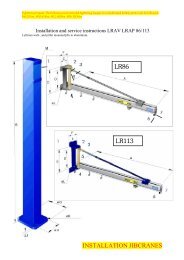
1. Bracket for concrete beam holds<br />
the square steel tube which is support<br />
point for a U-suspension.<br />
20<br />
www.TAWI.com<br />
Suspensions<br />
The <strong>LR</strong>-System has very rugged suspension mountings of universal<br />
type which permit various possibilities, for example suspension in steel<br />
beams, concrete ceilings and concrete beams. The universal beam<br />
suspension is designed to deal with a wide range of beam flange widths.<br />
In a corresponding manner the beam clamping washers can be used with<br />
varying flange thickness.<br />
Ceiling attachments are available for both fixed and free suspensions.<br />
The freely suspended mountings are provided with double ball couplings<br />
with bearing cups of Permaglide type. The bearing principle combined<br />
with the <strong>LR</strong>-System travelling crab concept, gives a uniquely light manual<br />
operation of the crane.<br />
2. Example of a suspension for curved<br />
concrete beams. The bracket supports<br />
the steel tube to which a U-suspension<br />
is attached.<br />
3. A freely suspended beam can be<br />
clamped to hold a U-suspension<br />
support point. No drilling required!
4. I-beam suspension, extended<br />
version. No modifications to<br />
supporting structures necessary.<br />
7. A U-suspension in a freestanding<br />
construction.<br />
www.TAWI.com<br />
5. Solution for low headroom; a steel<br />
support is installed into the side of<br />
the concrete beam.<br />
8. Ceiling suspension mounted<br />
directly into the cement ceiling.<br />
6. Solution for low headroom; a steel<br />
support is installed into the side of the<br />
curved concrete beam and supported<br />
at the lowest part of the beam.<br />
9. Extensions and struts are used to<br />
reach the desired level of suspension<br />
for the lifting equipment.<br />
21
1. 21100/B* (<strong>LR</strong>120)<br />
71100/B* (<strong>LR</strong>170)<br />
Beam suspension, short.<br />
5. 21800-100/B* (<strong>LR</strong>120)<br />
71800-100/B* (<strong>LR</strong>170)<br />
Ceiling suspension,<br />
100 mm extension.<br />
9. 21900-300 (<strong>LR</strong>120)<br />
71900-300 (<strong>LR</strong>170)<br />
21900-600 (<strong>LR</strong>120)<br />
71900-600 (<strong>LR</strong>170)<br />
U-suspension,<br />
300/600 mm extension.<br />
13. 25100 (<strong>LR</strong>120)<br />
75100 (<strong>LR</strong>170)<br />
Crane suspension.<br />
22<br />
2. 21700-100/B* (<strong>LR</strong>120)<br />
71700-100/B* (<strong>LR</strong>170)<br />
Beam suspension,<br />
100 mm extension.<br />
6. 21800-300/B* (<strong>LR</strong>120)<br />
71800-300/B* (<strong>LR</strong>170)<br />
21800-600/B* (<strong>LR</strong>120)<br />
71800-600/B* (<strong>LR</strong>170)<br />
Ceiling suspension,<br />
300/600 mm extension.<br />
10. 22100 (<strong>LR</strong>120)<br />
72100 (<strong>LR</strong>170)<br />
Trolley for lifting equipment.<br />
14. 23300 (<strong>LR</strong>120)<br />
73300 (<strong>LR</strong>170)<br />
End piece.<br />
*B indicates larger cc-distance between suspending bolts.<br />
www.TAWI.com<br />
Assembly parts, steel program<br />
3. 21700 -300/B* (<strong>LR</strong>120)<br />
71700 -300/B* (<strong>LR</strong>170)<br />
21700 -600/B* (<strong>LR</strong>120)<br />
71700 -600/B* (<strong>LR</strong>170)<br />
Beam suspension,<br />
300/600 mm extension.<br />
7. 21300 (<strong>LR</strong>120)<br />
71300 (<strong>LR</strong>170)<br />
U-suspension, short.<br />
11. 22200 (<strong>LR</strong>120)<br />
72200 (<strong>LR</strong>170)<br />
Trolley for lifting equipment.<br />
15. 23100 (<strong>LR</strong>120)<br />
73100 (<strong>LR</strong>170)<br />
Self-adjusting joint.<br />
4. 21200/B* (<strong>LR</strong>120)<br />
71200/B* (<strong>LR</strong>170)<br />
Ceiling suspension, short.<br />
8. 21900-100 (<strong>LR</strong>120)<br />
71900-100 (<strong>LR</strong>170)<br />
U-suspension,<br />
100 mm extension.<br />
12. 24300 (<strong>LR</strong>120)<br />
74300 (<strong>LR</strong>170)<br />
Cable trolley.
1. 81100/B* (<strong>LR</strong>86)<br />
31100/B* (<strong>LR</strong>113)<br />
Beam suspension, short.<br />
5. 81800-100/B* (<strong>LR</strong>86)<br />
31800-100/B* (<strong>LR</strong>113)<br />
Ceiling suspension,<br />
extension 100 mm.<br />
9. 81900-300 (<strong>LR</strong>86)<br />
31900-300 (<strong>LR</strong>113)<br />
81900-600 (<strong>LR</strong>86)<br />
31900-600 (<strong>LR</strong>113)<br />
U-suspension,<br />
extension 300/600 mm.<br />
13. 85100 (<strong>LR</strong>86)<br />
35100 (<strong>LR</strong>113)<br />
Crane suspension.<br />
2. 81700-100/B* (<strong>LR</strong>86)<br />
31700-100/B* (<strong>LR</strong>113)<br />
Beam suspension,<br />
extension 100 mm.<br />
6. 81800-300/B* (<strong>LR</strong>86)<br />
31800-300/B* (<strong>LR</strong>113)<br />
81800-600/B* (<strong>LR</strong>86)<br />
31800-600/B* (<strong>LR</strong>113)<br />
Ceiling suspension,<br />
extension 300/600 mm.<br />
10. 82100 (<strong>LR</strong>86)<br />
Trolley for lifting equipment.<br />
14. 83300 (<strong>LR</strong>86)<br />
33300 (<strong>LR</strong>113)<br />
End piece.<br />
*B indicates larger cc-distance between suspending bolts.<br />
www.TAWI.com<br />
Assembly parts, aluminium program<br />
3. 81700-300/B* (<strong>LR</strong>86)<br />
31700-300/B* (<strong>LR</strong>113)<br />
81700-600/B* (<strong>LR</strong>86)<br />
31700-600/B* (<strong>LR</strong>113)<br />
Beam suspension,<br />
extension 300/600 mm.<br />
7. 81300 (<strong>LR</strong>86)<br />
31300 (<strong>LR</strong>113)<br />
U-suspension, short.<br />
11. 32100 (<strong>LR</strong>113)<br />
Trolley for lifting equipment.<br />
15. 83100 (<strong>LR</strong>86)<br />
33100 (<strong>LR</strong>113)<br />
Self-adjusting joint.<br />
4. 81200/B* (<strong>LR</strong>86)<br />
31200/B* (<strong>LR</strong>113)<br />
Ceiling suspension, short.<br />
8. 81900-100 (<strong>LR</strong>86)<br />
31900-100 (<strong>LR</strong>113)<br />
U-suspension,<br />
extension 100 mm.<br />
12. 84300 (<strong>LR</strong>86)<br />
34300 (<strong>LR</strong>113)<br />
Cable trolleys.<br />
23
TH80<br />
TAWILift<br />
TAWI AB<br />
Transportgatan 1<br />
Box 10205<br />
434 23 KUNGSBACKA<br />
SWEDEN<br />
Tel +46 300 185 00<br />
Fax +46 300 189 90<br />
www.TAWI.com<br />
VacuEasylift, VacuMove,<br />
Levalair, VacuMyggan, VacuMyggen<br />
<strong>Lyftman</strong><br />
Bergtorpsvägen 43A<br />
183 64 TÄBY<br />
SWEDEN<br />
Tel +46 8 446 48 50<br />
Fax +46 8 446 48 55<br />
info@tawi.com<br />
www.tawi.com<br />
VacuCobra<br />
Protema<br />
UK 0510 – NY