

Three Track Thickness Gauge For Soft Strip ... - Vollmer America
Three Track Thickness Gauge For Soft Strip ... - Vollmer America
Three Track Thickness Gauge For Soft Strip ... - Vollmer America

Create successful ePaper yourself
Turn your PDF publications into a flip-book with our unique Google optimized e-Paper software.
<strong>Three</strong> <strong>Track</strong><br />
<strong>Thickness</strong> <strong>Gauge</strong><br />
<strong>For</strong> <strong>Soft</strong> <strong>Strip</strong><br />
Operating- & Service Instructions<br />
3f-E1 erstellt am 2.7.2001 geprüft am freigegeben am Bemerkungen<br />
Rev.01 Seiten: Name: Rietdorf Name: Name:
measuring - controlling - recording - automation - documentation<br />
G G G<br />
G<br />
G<br />
Content.................................................................................................. Page<br />
Safety Precautions, please read carefully! ................................................... 3<br />
Intended use of this machine ......................................................................... 3<br />
Spares .............................................................................................................. 3<br />
Design and Function ...................................................................................... 4<br />
VMF amplifier .................................................................................... 6<br />
Nominal size setting ........................................................................... 6<br />
Measurement head adjustment...................................................................... 8<br />
Alignment............................................................................................ 8<br />
Passline height .................................................................................... 8<br />
Measurement tracks............................................................................ 8<br />
Measurement load............................................................................... 9<br />
Measurement ................................................................................................ 10<br />
Calibration......................................................................................... 10<br />
Nominal size and tolerance limits ................................................... 11<br />
Measurement start and end .............................................................. 11<br />
Note.................................................................................................... 11<br />
Important note: ................................................................................. 11<br />
Pneumatics.................................................................................................... 12<br />
Maintenance ................................................................................................. 13<br />
Measurement rollers and guide roller ............................................. 13<br />
Measurement traverse ...................................................................... 13<br />
Transducers .................................................................................................. 13<br />
Trouble shooting .......................................................................................... 14<br />
If the gauge measures wrong ........................................................... 14<br />
If the gauge marks the strip ? ........................................................... 14<br />
Repairs .......................................................................................................... 15<br />
Transducer / Hard metal pin ............................................................ 15<br />
Measurement roller replacement ..................................................... 16<br />
Note.................................................................................................... 16<br />
Subject to change without prior notice<br />
2 3-<strong>Track</strong> <strong>Thickness</strong> <strong>Gauge</strong> Operating and Service Instructions<br />
3f-E1
FRIEDRICH VOLLMER Feinmeßgerätebau GmbH D-58093 Hagen/Germany Verbandsstraße 60 ( 0049 2334 / 507-0 Fax .. /53015<br />
3f-E1<br />
Safety Precautions, please read carefully!<br />
This gauge is meant to be used exclusively as a fix mounted component of<br />
a strip processing machine. The strip processing machine must not be started<br />
up until a written statement was made that the entire machine (into which<br />
the gauge is installed) is in accordance with the regulations of the EG-Maschinenrichtlinie<br />
89/392/EWG.<br />
The gauge manufacturer points out, that this includes the installation of an<br />
appropriate protection device. The protection device has to be made in such<br />
a way that the gauge operator does not face any hazard by the running or by<br />
the possibly breaking strip.<br />
Nobody is allowed close to the gauge as long as the mill's strip tension is on.<br />
This manual has to be handed to the machine operator, and one copy must<br />
be permanently available to operator and service personnel.<br />
Nobody is allowed to work on or with the gauge, before he has read and<br />
understood this manual. Feel free to call the <strong>Vollmer</strong> company in case of<br />
any questions (phone +49 2334 507 0).<br />
Hands or fingers which are put into the vertical guide behind the gauge or<br />
into the slidebase below the gauge, might get caught and heavily injured if<br />
the gauge head moves up/down or is traversed.<br />
The pneumatically operated guide rollers might cause injuries on hands and<br />
fingers. Under certain conditions, the guide rollers might close the gap unexpectedly.<br />
Therefore the pneumatic system must be depressurized before<br />
anybody starts to work on this gauge.<br />
The gauge head might get hot. Therefore check the temperature before touching<br />
the gauge head.<br />
Intended use of this machine<br />
This gauge must be used exclusively for the measurement of cold Lithium<br />
strip at a maximum speed of 30 meters per minute. The strip may be between<br />
100 and 250 mm wide and up to 300 microns thick. The gauge must<br />
be firmly installed in its intended position and electrically, electronically<br />
and pneumatically connected as intended by the <strong>Vollmer</strong> company. Any<br />
alteration might cause severe damage or injury.<br />
Spares<br />
Please order spares referring to the part number and drawing number of the<br />
enclosed documentation drawings. To speed up our work, please do also<br />
state the Project number which is written as P-Nr. on the identity plate of<br />
the gauge.<br />
Operating and Service Instructions 3-<strong>Track</strong> <strong>Thickness</strong> <strong>Gauge</strong><br />
We care about<br />
your Health.<br />
Please follow<br />
the safety<br />
precautions.<br />
Especially if<br />
you have many<br />
years of professional<br />
experience,<br />
you will be a<br />
3
P<br />
measuring - controlling - recording - automation - documentation<br />
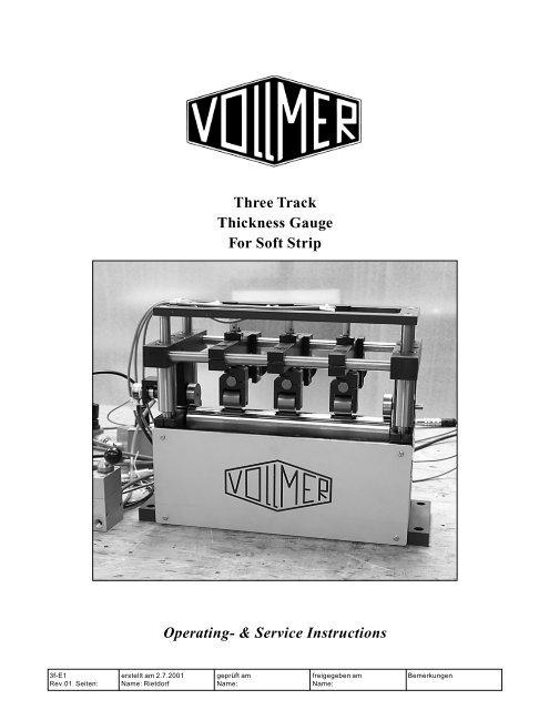
Design and Function<br />
This 3-track-gauge is designed to measure the thickness of strip with a soft<br />
surface simultaneously on three tracks.<br />
The strip, e.g. lithium, passes the gauge supported by the guide roller U.<br />
From the top side - above the guide roller - three measurement rollers M run<br />
on the strip. Each measurement roller is installed on a measurement lever L<br />
which can rotate around a bearing B when the roller runs over a "bump" or<br />
when it goes up or down due to strip thickness alterations. The up and down<br />
motion of each measurement lever is measured by an individual LVDT transducer<br />
T and indicated by an individual VMF measurement amplifier.<br />
The measuring traverse V can be lifted pneumatically, to ease the feeding<br />
of the strip end through the gauge. During calibrating and measuring, the<br />
weight of the measuring traverse is carried by two side rollers E. One of<br />
them drives rotary pulse encoder P so that the thickness data can be linked<br />
to their strip length position.<br />
The <strong>Vollmer</strong> 3-<strong>Track</strong> <strong>Thickness</strong> <strong>Gauge</strong> is designed to measure soft strip. The letters<br />
are explained in the text.<br />
4 3-<strong>Track</strong> <strong>Thickness</strong> <strong>Gauge</strong> Operating and Service Instructions<br />
M<br />
T<br />
V<br />
U<br />
E<br />
3f-E1
FRIEDRICH VOLLMER Feinmeßgerätebau GmbH D-58093 Hagen/Germany Verbandsstraße 60 ( 0049 2334 / 507-0 Fax .. /53015<br />
3f-E1<br />
V<br />
U<br />
Weight W can be adjusted to alter the measurement load which the measurement roll<br />
puts on the strip.<br />
At its rear end, each transducer has a differential transformer. The movable<br />
core of this transformer is connected to the measurement tip which is resting<br />
on the measurement lever. In this way any movement of the measurement<br />
roller is measured inductively.<br />
All changes within each of the three transducers are passed to a VMF measurement<br />
amplifier, where they are subtracted from the nominal value (if<br />
one was is set). The amplifier indicates a measurement result as deviation<br />
from zero, i.e. the difference to the nominal size. Nominal size is set electronically<br />
by a thumb when decade switch for each measurement track.<br />
The three measurement rollers can be shifted laterally, so that they can measure<br />
the strip thickness on any desired distance to the strip edge.<br />
Amplifier measurement data can be used as signal for controlling and for<br />
quality control documentation according to ISO 9000. It is available on two<br />
analog voltage outputs.<br />
Operating and Service Instructions 3-<strong>Track</strong> <strong>Thickness</strong> <strong>Gauge</strong><br />
M<br />
L<br />
W<br />
E<br />
5
measuring - controlling - recording - automation - documentation<br />
FS4<br />
VMF amplifier<br />
The gauge is always installed with one VMF measurement amplifier for<br />
each measurement track. The measurement amplifier continuously indicates<br />
the difference between measured strip thickness and selected nominal size.<br />
The amplifier in detail is described in a separate manual.<br />
The operator can select the resolution of the analogue indicator by the measurement<br />
range selector MB. Full deflection can indicate from 1000 microns<br />
(.030 ") down to 10 microns (.0003"). The zero potentiometer NP allows to<br />
eliminate small deviations of the gauge zero.<br />
Nominal size setting<br />
Nominal size is set for each track by the thumb wheel decade switch FS4<br />
below the amplifier. The nominal size selector FS4 shows the selected nominal<br />
size in microns (or in steps of 0.0001", depending on the FS4 type).<br />
MB NP<br />
I/O C1<br />
Measurement amplifier cabinet of the <strong>Vollmer</strong> 3-<strong>Track</strong> <strong>Thickness</strong> <strong>Gauge</strong>: Thumb wheel<br />
decade switch D for nominal size setting in thousandth inches; main Power switch O/<br />
I ; Calibration roller drive on/off C1 and calibration roller drive speed selector C2.<br />
6 3-<strong>Track</strong> <strong>Thickness</strong> <strong>Gauge</strong> Operating and Service Instructions<br />
C2<br />
3f-E1
FRIEDRICH VOLLMER Feinmeßgerätebau GmbH D-58093 Hagen/Germany Verbandsstraße 60 ( 0049 2334 / 507-0 Fax .. /53015<br />
3f-E1<br />
If the required material thickness - e.g. 200 µm - is entered as nominal size<br />
and if the measurement is 202 µm, the amplifier will indicate +2 µm.<br />
So it is possible to stay within the highest sensitivity range of the indicator<br />
no matter of the material thickness. In this range the full deflection of the<br />
indicator covers a range of +/-10 microns.<br />
Operating and Service Instructions 3-<strong>Track</strong> <strong>Thickness</strong> <strong>Gauge</strong><br />
7
measuring - controlling - recording - automation - documentation<br />
Measurement head adjustment<br />
Alignment<br />
When the gauge is installed into an inspection line, installation height and<br />
levelling of the gauge are derived from the inspection table. If the gauge<br />
was removed from its position, take care to reinstall the gauge's base angular<br />
to the passline and parallel to roll axes in the mill.<br />
Passline height<br />
The gauge should be installed at such height that the lower guide roller touch<br />
the strip without lifting it considerably. The height is correct if the guide<br />
roller is permanently driven by the passing strip.<br />
J<br />
K<br />
Measurement<br />
tracks<br />
The Allen bolts J in the front<br />
end of each measurement<br />
arm installation clamp the<br />
measurement arms to the<br />
front side rod. To alter the<br />
measurement track, loosen<br />
bolt J, shift the measurement<br />
arm to desired<br />
position and clamp it there.<br />
At their rear ends, the measurement<br />
arms can slide free<br />
on the rear side rod.<br />
The measurement arms are<br />
clamped at the front end, but<br />
have a slide bushing at the rear<br />
end. The measurement load<br />
weights are fastened each with<br />
a grub screw K.<br />
8 3-<strong>Track</strong> <strong>Thickness</strong> <strong>Gauge</strong> Operating and Service Instructions<br />
3f-E1
FRIEDRICH VOLLMER Feinmeßgerätebau GmbH D-58093 Hagen/Germany Verbandsstraße 60 ( 0049 2334 / 507-0 Fax .. /53015<br />
3f-E1<br />
Measurement load<br />
The weight of the measurement lever and the pressure of the transducer's<br />
measurement spring push the transducer measurement roller down on the<br />
strip. The more load is resting on the measurement roller, the better it will<br />
follow the strip surface. Limit for that load is the hardness of the strip surface.<br />
Reduce the measurement load when the gauge marks the strip. Measuring<br />
very thin strip might as well require a reduced measurement load.<br />
Increase the measurement load when the amplifier indicates sudden peaks<br />
during a measurement. This shows that the measurement roller is bouncing<br />
on the strip surface.<br />
<strong>For</strong> measurement load adjustment loosen the grub screw K and shift the<br />
weight:<br />
- increase load by shifting towards the rear side of the gauge<br />
- decrease load by shifting towards the front side of the gauge<br />
Shift all the three weights and tighten the grub screw J in the desired position.<br />
Operating and Service Instructions 3-<strong>Track</strong> <strong>Thickness</strong> <strong>Gauge</strong><br />
9
measuring - controlling - recording - automation - documentation<br />
V<br />
Measurement<br />
Calibration<br />
The transducers measure zero, when the measurement roller is resting on<br />
the guide roller. However, there are always imperfections in roundness and<br />
eccentricity. To eliminate those as far as possible, calibration is done on<br />
rotating rollers, and of course without a strip in the gauge.<br />
<strong>For</strong> calibration, the calibration drive motor CD is pneumatically lifted so<br />
that it drives the guide roller U. The lifting is actuated by a manually operated<br />
pneumatic valve ("Calibration") . The switch C1 (see page 6) starts the<br />
motor and the selector knob C2 controls the drive speed.<br />
When the calibration motor drives the guide roller, the measurement traverse<br />
is lowered by means of the second manually operated pneumatic valve ("Measuring<br />
Traverse"). The traverse is lowered so that the measurement rollers<br />
come down onto the guide roller.<br />
Set nominal size to zero on each measurement arm. Then select the highest<br />
sensitivity range on each of the VMF amplifiers (metric: ±10µm or inches:<br />
± 0,3 thousandth ", see selector MB on page 6). Then use the NP potentiometer<br />
to adjust the indicator needle so that it is deviated to + and to - for the<br />
same amount, i.e. that it swings symmetrically around zero. The swinging<br />
is caused by the form imperfections mentioned above. When the adjustment<br />
is finished, lower the calibration motor and switch it off. Then check<br />
the gauge for zero.<br />
Zero checking should be performed regularly. Lift the measuring traverse<br />
and lower it a few times and check, if zero returns. If so, measurement can<br />
begin, if not, check the entire gauge.<br />
10 3-<strong>Track</strong> <strong>Thickness</strong> <strong>Gauge</strong> Operating and Service Instructions<br />
CD<br />
U<br />
3f-E1
FRIEDRICH VOLLMER Feinmeßgerätebau GmbH D-58093 Hagen/Germany Verbandsstraße 60 ( 0049 2334 / 507-0 Fax .. /53015<br />
3f-E1<br />
Nominal size and tolerance limits<br />
After the zero check, nominal strip thickness and width are set mechanically<br />
(by fine adjustment/micrometer) or electronically by the optional FS4<br />
thumb wheel switch.<br />
The upper and lower tolerance limits in microns can either be entered into<br />
the electronic classifier 2S or 4S (optional item, see separate instructions)<br />
or into the VMF 2000 amplifier (optional item, see separate instructions).<br />
Measurement start and end<br />
Set the strip thickness nominal size for each track by<br />
the thumb wheel decade switch FS4 below the amplifier<br />
(the FS4 shows the nominal size in microns or in<br />
steps of 0.0001", depending on the FS4 type).<br />
Then lift the measurement traverse so that the strip<br />
end can be fed through the gauge.<br />
Lower the measurement traverse after the strip was<br />
inserted and when it is firmly guided before and behind<br />
the gauge.<br />
Note<br />
The strip must nor run under<br />
the two side rollers (see pages<br />
4/5). They need to roll directly<br />
on the lower guide roller.<br />
Now the three VMF amplifiers<br />
indicate the strip thickness<br />
deviation from nominal<br />
size. The weight of the<br />
measuring traverse is carried<br />
by the two side rollers<br />
E. This allows to<br />
measure with a very low<br />
measurement load and in<br />
addition it eliminates possible<br />
errors due to temperature<br />
extension.<br />
Important note:<br />
Always lift the measurement<br />
rollers and guide the strip end<br />
through the gauge carefully.<br />
<strong>Strip</strong> tension must not be<br />
switched off and the strip end<br />
must not pass the gauge unattended<br />
as it may cause serious<br />
damage.<br />
Operating and Service Instructions 3-<strong>Track</strong> <strong>Thickness</strong> <strong>Gauge</strong><br />
E<br />
.<br />
11
measuring - controlling - recording - automation - documentation<br />
Pneumatics<br />
PM PL<br />
The gauge has two pneumatic circuits. The must be fed with dry compressed<br />
air of about 3 bar (45 PSI).<br />
The working pressure measuring traverse circuit is controlled by valve PM.<br />
The traverse is lifted by a pressure of about 0,2 bar (1,5 PSI). The pressure<br />
is correct, when the traverse lifts quickly and travels up to its limit stop<br />
without stopping before. The pressure is too high when the traverse hits its<br />
upper limit stop unnecessary hard. Each cylinder has adjustable chokes for<br />
the "down" motion as well as for the "up" motion.<br />
Valve PL controls the working pressure to lift the calibration motor. Factory<br />
setting is 0,8 bar (12 PSI). The optimum working pressure is set in the<br />
same way as described in the previous paragraph. The cylinder has got chokes<br />
to set the optimum speed at a given pressure.<br />
A manually operated valve for each circuit opens/shuts the actual working<br />
flow of compressed air.<br />
12 3-<strong>Track</strong> <strong>Thickness</strong> <strong>Gauge</strong> Operating and Service Instructions<br />
3f-E1
FRIEDRICH VOLLMER Feinmeßgerätebau GmbH D-58093 Hagen/Germany Verbandsstraße 60 ( 0049 2334 / 507-0 Fax .. /53015<br />
3f-E1<br />
Maintenance<br />
The thickness gauge does not need much maintenance. Only the measurement<br />
rollers and the guide roller are subject to wear. The entire gauge needs<br />
to be cleaned regularly in order to avoid dirt deposits which might block<br />
movable parts.<br />
Measurement rollers and guide roller<br />
l Clearance?<br />
The rollers have to move freely. They may have only little axial clearance<br />
and the measurement rollers must not have any obvious radial clearance.<br />
Blocking rolls mark the strip.<br />
ð Replace defective rollers (if the roller's surface is OK, replace only the<br />
bearings)<br />
l Deposits on the surface?<br />
If dirt deposits have accumulated on the the rollers, they cannot run smooth<br />
on the strip and might mark the strip.<br />
ð clean rollers regularly (if necessary), replace defective rollers (rework<br />
if possible)<br />
Measurement traverse<br />
l Easy movable?<br />
The traverse must go up and down to its mechanical limit stops without<br />
stopping under way. It might get stuck because of major dirt deposits in<br />
the gauge mechanics, or if - after a long time of operation - the ball guides<br />
are worn. This would cause measurement errors.<br />
ð Clean the gauge, call <strong>Vollmer</strong> for repair if the ball guides are worn<br />
Transducers<br />
l Ram easy movable ?<br />
The transducer rams must be easy to be pushed in and spring back immediately.<br />
l Measurement tips worn or damaged?<br />
If the calibration or the zero point are unstable, remove the transducer<br />
and check the measurement tips:<br />
l Ball dirty or worn?<br />
The ball at the end of the measurement ram must be clean, crowned and<br />
polished to achieve accurate measurement results. Worn balls with flat<br />
spots or broken out chromium skin may cause measurement errors.<br />
ð Replace transducer tip<br />
l Hard metal pin dirty, worn or damaged ?<br />
The hard metal pin adjacent to the transducer ball must be crowned and<br />
polished to achieve accurate measurement results. Worn balls with flat<br />
spots or broken out chromium skin may cause measurement errors.<br />
ð Replace hard metal pin screw.<br />
Operating and Service Instructions 3-<strong>Track</strong> <strong>Thickness</strong> <strong>Gauge</strong><br />
13
measuring - controlling - recording - automation - documentation<br />
Trouble shooting<br />
If the gauge measures wrong<br />
l Wrong point remeasured ?<br />
Cross profile strip thickness varies in many cases. If the gauge is checked,<br />
strip thickness must be measured in the same distance from the edge as<br />
the transducers have measured.<br />
ð check the strip thickness at correct edge distance<br />
l Transducers dirty ?<br />
In a very dirty environment, the rams of transducers sometimes get too<br />
sticky, so that they do not shut completely. If the gauge is then set to<br />
zero, the indication of a following measurement is too low. After cleaning<br />
the transducer ram should slide easy in its bushing or bearing for a<br />
quite long period of time.<br />
ð increase cleaning frequency<br />
l Transducers clamped too hard?<br />
If the clamp screws in the C-frame are clamped too hard, they possibly<br />
distort the transducer housing which increases the friction in the ram<br />
guiding.<br />
ð loosen the clamp screw and re-tighten them with moderate force<br />
l <strong>Gauge</strong> zero not constant?<br />
If the measurement ball at the tip of the transducer ram is loose, then the<br />
indication is incorrect.<br />
ð fasten it<br />
l Indication too low?<br />
If the transducers are not clamped tight enough in the measurement traverse,<br />
they might be shifted in their bore. <strong>Gauge</strong> zero is then shifted too.<br />
l Additional check for gauges with decade switch (type FS3/FS4): If a<br />
new transducer was installed, the adjustment of the measurement amplifier<br />
to the nominal size selector has to be checked by a slip gauge. Set the<br />
gauge to 0 and insert 500 micron slip gauge. Then set the decade switch<br />
to 500 and check, if the gauge measures zero. If not,<br />
ð make a coarse adjustment by the sensitivity potentiometer on the X3 or<br />
X2 input (whichever is in use) at the back of the VMF 3/11 or 3/22 amplifier.<br />
<strong>For</strong> fine adjustment to the nominal size selector switch, use the<br />
X9 sensitivity potentiometer (see the VMF manual for details).<br />
l Measurement load too high ?<br />
ð reduce it<br />
l Roller surface defective ?<br />
ð replace roller with bearings<br />
If the gauge marks the strip ?<br />
l Roller blocked ?<br />
ð Replace roller. If the roller surface is not damaged, replace only the bearings.<br />
14 3-<strong>Track</strong> <strong>Thickness</strong> <strong>Gauge</strong> Operating and Service Instructions<br />
3f-E1
FRIEDRICH VOLLMER Feinmeßgerätebau GmbH D-58093 Hagen/Germany Verbandsstraße 60 ( 0049 2334 / 507-0 Fax .. /53015<br />
3f-E1<br />
Repairs<br />
Transducer / Hard metal pin<br />
MA<br />
TC<br />
FC<br />
The transducers T can easily be removed from their clamping bores in the<br />
measurement arms MA. Loosen the clamp screw TC and pull the transducer<br />
off the clamping fixture. When inserting the transducer, it needs to be set<br />
back into the same clamping fixture. If a new transducer is installed, or if a<br />
old transducer gets connected to another than its original VMF input, the<br />
amplifier requires new sensitivity adjustment (see amplifier manual).<br />
Check the hard metal pin HP for dirt or wear before inserting the transducer.<br />
The surface has to be crowned and smooth. Replace the hard metal pin it<br />
if the surface is damaged. Loosen the clamp screw HC and then unscrew the<br />
hard metal pin. Insert a new HP and clamp it. Readjust the transducer position<br />
afterwards. It is helpful to remove the measurement roller fixture for<br />
this work (see following page). Put a drop of oil on top of HP to reduce<br />
friction.<br />
Insert the transducer while it is connected to the amplifier. Clamp it where<br />
the amplifier indicates zero. Eliminate minor deviations by the zero point<br />
potentiometer.<br />
Then check the strip thickness gauge with a slip gauge e.g. 500 µm. If the<br />
error exceeds the tolerance limit, check the VMF adjustment to the nominal<br />
size selector and the transducer measurement tips.<br />
Operating and Service Instructions 3-<strong>Track</strong> <strong>Thickness</strong> <strong>Gauge</strong><br />
T<br />
15
W<br />
PR<br />
measuring - controlling - recording - automation - documentation<br />
Measurement roller replacement<br />
If only the measurement roller needs to be replaced, leave the fixture MF<br />
untouched and remove the roller as described in the following paragraph. If<br />
you want to remove the fixture see the subsequent paragraphs.<br />
Without fixture removal: Put a cloth (as a cushion) between the roller U<br />
and the roller M. Unscrew the Allen bolts PR on both sides of the axle and<br />
take out roller. The roller bearings are held in place by a snap ring and may<br />
be pushed out after that ring was removed.<br />
HC<br />
M<br />
L<br />
With fixture removal: The<br />
measurement roller fixture<br />
MF is clamped to the measurement<br />
lever L by clamp<br />
screw FC (see previous<br />
page).<br />
Loosen the screw FC and<br />
pull the fixture MF of the<br />
measurement lever.<br />
Note<br />
Do not damage the transducer<br />
by bending its rod when<br />
pushing the fixture MF back<br />
into position.<br />
Once the fixture is removed,<br />
the pin screw HP is easily<br />
accessible for cleaning or<br />
replacement.<br />
Loosen the two pin screws<br />
PR (one on each side) and<br />
take the roller off the fixture.<br />
Re-insert a new roller.<br />
Do not overtighten the<br />
small PR pin screws.<br />
Push the transducer rod up<br />
for a few millimetres and<br />
then put the measurement<br />
roller fixture back MF onto<br />
the measurement lever L.<br />
At this point, the clamping screws HC and PR need to be tightened, but not<br />
the clamp screw FC. Move the fixture back and forth until you have found<br />
the highest point of the guide roller (indicated by the VMF. Before tightening<br />
FC in this position, the roller still needs to be aligned. Align the roller<br />
by pushing the weight W up while the screw FC is loose. This will align the<br />
measurement roller parallel to the guide roller. Now tighten FC carefully.<br />
Finally the transducer zero needs to be readjusted.<br />
16 3-<strong>Track</strong> <strong>Thickness</strong> <strong>Gauge</strong> Operating and Service Instructions<br />
MF<br />
HP<br />
3f-E1


