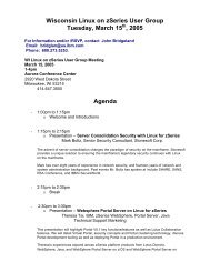
- Page 1:
z/VM CP Commands and Utilities Refe
- Page 4 and 5:
Note! Before using this information
- Page 6 and 7:
iv z/VM: CP Commands and Utilities
- Page 8 and 9:
vi z/VM: CP Commands and Utilities
- Page 10 and 11:
viii z/VM: CP Commands and Utilitie
- Page 12 and 13:
x z/VM: CP Commands and Utilities R
- Page 14 and 15:
xii z/VM: CP Commands and Utilities
- Page 16 and 17:
xiv z/VM: CP Commands and Utilities
- Page 18 and 19:
xvi z/VM: CP Commands and Utilities
- Page 20 and 21:
v Send your comments by electronic
- Page 22 and 23:
SCSI FCP Disk Support The CP comman
- Page 24 and 25:
e specified in the system configura
- Page 26 and 27:
xxiv z/VM: CP Commands and Utilitie
- Page 28 and 29:
Introduction Command Structure When
- Page 30 and 31:
Introduction The minimum acceptable
- Page 32 and 33:
Introduction Syntax Diagram Convent
- Page 34 and 35:
Introduction Table 2. Privilege Cla
- Page 36 and 37:
Introduction System Operator’s Co
- Page 38 and 39:
ASTERISK (*) ASTERISK (*) ►► *
- Page 40 and 41:
#CP 14 z/VM: CP Commands and Utilit
- Page 42 and 43:
ACTIVATE ISLINK ACTIVATE ISLINK ►
- Page 44 and 45:
ASSOCIATE EXIT ASSOCIATE EXIT ►
- Page 46 and 47:
ASSOCIATE EXIT 20 z/VM: CP Commands
- Page 48 and 49:
ASSOCIATE EXIT HCP6704E Missing tok
- Page 50 and 51:
ASSOCIATE MESSAGES / MSGS Usage Not
- Page 52 and 53:
ATTACH ATTACH ►► ATTach rdev ld
- Page 54 and 55:
ATTACH 28 z/VM: CP Commands and Uti
- Page 56 and 57:
| | | | | | ATTACH Usage Notes 30 z
- Page 58 and 59:
| | | ATTACH Responses 32 z/VM: CP
- Page 60 and 61:
ATTACH been attached to either the
- Page 62 and 63:
| | | | ATTACH HCP1104E DASD rdev h
- Page 64 and 65:
| | | | | | | | | AUTOLOG AUTOLOG
- Page 66 and 67:
AUTOLOG Responses 10. Users defined
- Page 68 and 69:
BACKSPACE/BACKWARD BACKSPACE/BACKWA
- Page 70 and 71:
BACKSPACE/BACKWARD HCP418E {rdev|vd
- Page 72 and 73:
BEGIN Messages HCP002E Invalid oper
- Page 74 and 75:
CHANGE Options for Reader, Printer,
- Page 76 and 77:
CHANGE Options 50 z/VM: CP Commands
- Page 78 and 79:
CHANGE 52 z/VM: CP Commands and Uti
- Page 80 and 81:
CHANGE TO userid indicates the user
- Page 82 and 83:
CHANGE Messages HCP002E Invalid ope
- Page 84 and 85:
CLOSE CLOSE ►► Close Notes: CON
- Page 86 and 87:
CLOSE Options 60 z/VM: CP Commands
- Page 88 and 89:
CLOSE HOld NOHold controls the user
- Page 90 and 91:
CLOSE available for processing. You
- Page 92 and 93:
CLOSE SEQ sss identifies the sequen
- Page 94 and 95:
CLOSE HCP1551E value is an invalid
- Page 96 and 97:
COMMANDS Messages diag1,2 ... are t
- Page 98 and 99:
COMMIT Messages rdev Cache fast wri
- Page 100 and 101:
COUPLE COUPLE ►► COUPLE Authori
- Page 102 and 103:
COUPLE Messages is the normal respo
- Page 104 and 105:
CP CP ►► CP Authorization Purpo
- Page 106 and 107:
CPACCESS Usage Notes 80 z/VM: CP Co
- Page 108 and 109:
CPACCESS HCP102E DASD vdev forced R
- Page 110 and 111:
CPCACHE Usage Notes Responses Messa
- Page 112 and 113:
CPHX Messages Response 2: If your u
- Page 114 and 115:
CPLISTFILE CPLISTFILE ►► CPLIST
- Page 116 and 117:
CPLISTFILE Usage Notes Responses IS
- Page 118 and 119:
CPRELEASE CPRELEASE ►► CPRELeas
- Page 120 and 121:
CPTRAP CPTRAP Purpose Messages CP d
- Page 122 and 123:
CPTYPE Usage Notes Responses Messag
- Page 124 and 125:
CPU Usage Notes Responses Messages
- Page 126 and 127:
CPVLOAD HCP6704E Missing token at e
- Page 128 and 129:
CPXLOAD (RECFM F) and a logical rec
- Page 130 and 131:
CPXLOAD Responses 3. The customer-w
- Page 132 and 133:
CPXLOAD HCP2772E Relocatable addres
- Page 134 and 135:
CPXUNLOAD Responses Messages them.
- Page 136 and 137:
DEACTIVE ISLINK DEACTIVE ISLINK ►
- Page 138 and 139:
DEDICATE Responses Messages If a pr
- Page 140 and 141:
DEFINE HCP092E Device vdev not defi
- Page 142 and 143:
DEFINE HCP6005E Option option is no
- Page 144 and 145:
DEFINE HCP6847E You may not define
- Page 146 and 147:
DEFINE ALIAS Usage Notes 120 z/VM:
- Page 148 and 149:
DEFINE CFLINK DEFINE CFLINK ►►
- Page 150 and 151:
DEFINE CHPID / PATH DEFINE CHPID /
- Page 152 and 153:
DEFINE CHPID / PATH Case 3: (1) SHA
- Page 154 and 155:
DEFINE CHPID / PATH 128 z/VM: CP Co
- Page 156 and 157:
DEFINE CHPID / PATH 130 z/VM: CP Co
- Page 158 and 159:
DEFINE CHPID / PATH Responses 5. To
- Page 160 and 161:
DEFINE COMMAND / CMD DEFINE COMMAND
- Page 162 and 163:
DEFINE COMMAND / CMD manager (ESM)
- Page 164 and 165:
DEFINE COMMAND / CMD Responses 9. T
- Page 166 and 167:
DEFINE CONSOLE DEFINE CONSOLE ►
- Page 168 and 169:
DEFINE CPOWNED Usage Notes Response
- Page 170 and 171:
DEFINE CPU Responses 4. When a virt
- Page 172 and 173:
DEFINE CRYPTO Examples Responses Me
- Page 174 and 175:
DEFINE CTCA Usage Notes Responses 1
- Page 176 and 177:
DEFINE CU / CNTLUNIT Operands 150 z
- Page 178 and 179:
DEFINE CU / CNTLUNIT 152 z/VM: CP C
- Page 180 and 181:
DEFINE CU / CNTLUNIT Responses 3. F
- Page 182 and 183:
DEFINE DEVICE / IODEVICE Authorizat
- Page 184 and 185:
DEFINE DEVICE / IODEVICE 158 z/VM:
- Page 186 and 187:
DEFINE DIAGNOSE DEFINE DIAGNOSE ►
- Page 188 and 189:
DEFINE DIAGNOSE Usage Notes 162 z/V
- Page 190 and 191:
DEFINE DIAGNOSE query diagnose 18c
- Page 192 and 193:
DEFINE EXIT Usage Notes Examples 3.
- Page 194 and 195:
DEFINE GRAF DEFINE GRAF ►► DEFi
- Page 196 and 197:
DEFINE LAN 170 z/VM: CP Commands an
- Page 198 and 199:
DEFINE LAN Responses Response 1: LA
- Page 200 and 201:
DEFINE MDISK DEFINE MDISK ►► DE
- Page 202 and 203:
DEFINE NIC DEFINE NIC ►► DEFine
- Page 204 and 205:
DEFINE MSGPROC DEFINE MSGPROC ►
- Page 206 and 207:
DEFINE MSGPROC 180 z/VM: CP Command
- Page 208 and 209:
DEFINE (Spooling Device) 2540P spec
- Page 210 and 211:
DEFINE (Spooling Device) Examples R
- Page 212 and 213:
DEFINE STORAGE .size is the size of
- Page 214 and 215:
DEFINE STORAGE Response 3: (when CO
- Page 216 and 217:
DEFINE (Temporary Disk) DEFINE (Tem
- Page 218 and 219:
DEFINE TIMEZONE DEFINE TIMEZONE ►
- Page 220 and 221:
DEFINE VECTOR DEFINE VECTOR ►►
- Page 222 and 223:
DEFINE (Virtual Device) DEFINE (Vir
- Page 224 and 225:
DEFINE (Virtual Disk in Storage) DE
- Page 226 and 227:
DEFINE VSWITCH DEFINE VSWITCH ►
- Page 228 and 229:
DEFINE VSWITCH Usage Notes 202 z/VM
- Page 230 and 231:
DEFINE VSWITCH Examples Responses M
- Page 232 and 233:
DEFSEG If other pages in the segmen
- Page 234 and 235:
DEFSEG Usage Notes 208 z/VM: CP Com
- Page 236 and 237:
DEFSEG Examples Messages HCP002E In
- Page 238 and 239:
DEFSYS DEFSYS ►► ► DEFSYS PAR
- Page 240 and 241:
DEFSYS Options 214 z/VM: CP Command
- Page 242 and 243:
DEFSYS Examples Messages 13. If you
- Page 244 and 245:
DELETE CHPID / PATH DELETE CHPID /
- Page 246 and 247:
DELETE CHPID / PATH HCP6806E Dynami
- Page 248 and 249:
DELETE CU / CNTLUNIT Responses Mess
- Page 250 and 251:
DELETE DEVICE / IODEVICE Usage Note
- Page 252 and 253:
DELETE EDEVICE DELETE EDEVICE ►
- Page 254 and 255:
DELETE RDEVICE DELETE RDEVICE ►
- Page 256 and 257:
DESTAGE DESTAGE ►► DESTAGE Auth
- Page 258 and 259:
DETACH DETACH Purpose Usage Notes M
- Page 260 and 261:
| | | DETACH HCP6324I An unexpected
- Page 262 and 263:
DETACH CFLINK Messages HCP020E User
- Page 264 and 265:
DETACH CPU STORAGE CLEARED - SYSTEM
- Page 266 and 267:
DETACH CRYPTO Messages Response 2:
- Page 268 and 269:
DETACH LAN Responses 2. DETACH LAN
- Page 270 and 271:
DETACH MSGPROC DETACH MSGPROC ►
- Page 272 and 273:
DETACH (Real Device) Usage Notes 24
- Page 274 and 275:
DETACH (Real Device) OSA Open Syste
- Page 276 and 277:
DETACH VECTOR DETACH VECTOR ►►
- Page 278 and 279:
DETACH (Virtual Device) DETACH (Vir
- Page 280 and 281:
DETACH (Virtual Device) is the resp
- Page 282 and 283:
DETACH XSTORE DETACH XSTORE Authori
- Page 284 and 285:
DIAL DIAL ►► Dial Authorization
- Page 286 and 287:
DIAL Messages HCP011E Invalid devic
- Page 288 and 289:
DISABLE (Device) Usage Notes Respon
- Page 290 and 291:
DISABLE COMMAND / CMD Usage Notes R
- Page 292 and 293:
DISABLE DIAGNOSE DISABLE DIAGNOSE
- Page 294 and 295:
DISABLE DIAGNOSE Messages HCP002E I
- Page 296 and 297:
DISABLE EXITS Responses Messages 7.
- Page 298 and 299:
DISABLE HCD Responses Note that onc
- Page 300 and 301:
DISASSOCIATE DISASSOCIATE ►► DI
- Page 302 and 303:
DISASSOCIATE Messages query cplangl
- Page 304 and 305:
DISCARD PINNED Messages If the orig
- Page 306 and 307:
DISCONNECT Responses 6. If your ins
- Page 308 and 309:
DISPLAY DISPLAY Purpose Usage Notes
- Page 310 and 311:
DISPLAY Messages can enter the DISP
- Page 312 and 313:
DISPLAY ACCESS LIST DISPLAY ACCESS
- Page 314 and 315:
DISPLAY CRYPTO DOMAIN INDEX DISPLAY
- Page 316 and 317:
DISPLAY Guest Storage (ESA/XC) acce
- Page 318 and 319:
DISPLAY Guest Storage (ESA/XC) 292
- Page 320 and 321:
DISPLAY Guest Storage (ESA/XC) Resp
- Page 322 and 323:
DISPLAY Guest Storage (ESA/390) DIS
- Page 324 and 325:
DISPLAY Guest Storage (ESA/390) 298
- Page 326 and 327:
DISPLAY Guest Storage (ESA/390) Usa
- Page 328 and 329:
DISPLAY Guest Storage (ESA/390) For
- Page 330 and 331:
DISPLAY Guest Storage (z/Architectu
- Page 332 and 333:
DISPLAY Guest Storage (z/Architectu
- Page 334 and 335:
DISPLAY Guest Storage (z/Architectu
- Page 336 and 337:
DISPLAY Guest Storage (z/Architectu
- Page 338 and 339:
DISPLAY Guest Storage (z/Architectu
- Page 340 and 341:
DISPLAY Host Storage at the address
- Page 342 and 343:
DISPLAY Host Storage Response 4: Hh
- Page 344 and 345:
DISPLAY Linkage Stack ED-ADDR The l
- Page 346 and 347:
DISPLAY Linkage Stack PSW PC-NUM nn
- Page 348 and 349:
DISPLAY PREFIX DISPLAY PREFIX ►
- Page 350 and 351:
DISPLAY PSW Responses v bits 0-31 a
- Page 352 and 353:
DISPLAY PSWG DISPLAY PSWG ►► No
- Page 354 and 355:
DISPLAY Registers DISPLAY Registers
- Page 356 and 357:
DISPLAY Registers Usage Notes Respo
- Page 358 and 359:
DISPLAY Registers The content of ea
- Page 360 and 361:
DISPLAY SCHIB DISPLAY SCHIB ►►
- Page 362 and 363:
DISPLAY SCHIB 336 z/VM: CP Commands
- Page 364 and 365:
DISPLAY Vector VP 338 z/VM: CP Comm
- Page 366 and 367:
DISPLAY Vector Vxn = ZERO (IN-USE B
- Page 368 and 369:
DRAIN (Disk) Usage Notes Responses
- Page 370 and 371:
DRAIN UR Usage Notes Responses 1. U
- Page 372 and 373:
DRAIN UR Continued: CL c typ You re
- Page 374 and 375:
DRAIN UR IMAGE imagelib specifies t
- Page 376 and 377:
DRAIN UR HCP413E Command processing
- Page 378 and 379:
DUMP 3. You can assign a dumpid to
- Page 380 and 381:
DUMP Messages R03F1AB40 00000000 00
- Page 382 and 383:
DUMP ACCESS LIST 356 z/VM: CP Comma
- Page 384 and 385:
DUMP Guest Storage (ESA/XC) DUMP Gu
- Page 386 and 387:
DUMP Guest Storage (ESA/XC) 360 z/V
- Page 388 and 389:
DUMP Guest Storage (ESA/XC) Usage N
- Page 390 and 391:
DUMP Guest Storage (ESA/XC) Respons
- Page 392 and 393:
DUMP Guest Storage (ESA/390) DUMP G
- Page 394 and 395:
DUMP Guest Storage (ESA/390) 368 z/
- Page 396 and 397:
DUMP Guest Storage (ESA/390) Usage
- Page 398 and 399:
DUMP Guest Storage (ESA/390) Respon
- Page 400 and 401:
DUMP Guest Storage (ESA/390) If you
- Page 402 and 403:
DUMP Guest Storage (z/Architecture)
- Page 404 and 405:
DUMP Guest Storage (z/Architecture)
- Page 406 and 407:
DUMP Guest Storage (z/Architecture)
- Page 408 and 409:
DUMP Guest Storage (z/Architecture)
- Page 410 and 411:
DUMP Host Storage DUMP Host Storage
- Page 412 and 413:
DUMP Host Storage Usage Notes Respo
- Page 414 and 415:
DUMP Host Storage Command complete
- Page 416 and 417:
DUMP LKS Responses 6. For more info
- Page 418 and 419:
DUMP LKS ED-ADDR U ET SI RFS NES PK
- Page 420 and 421:
DUMP PREFIX DUMP PREFIX ►► DUmp
- Page 422 and 423:
DUMP PSW Responses When the DUMP PS
- Page 424 and 425:
DUMP PSWG DUMP PSWG ►► DUmp Not
- Page 426 and 427:
DUMP Registers DUMP Registers ►
- Page 428 and 429:
DUMP Registers Usage Notes Response
- Page 430 and 431:
DUMP Registers Dump Register ECR nn
- Page 432 and 433:
DUMP SCHIB DUMP SCHIB ►► DUmp N
- Page 434 and 435:
DUMP SCHIB 408 z/VM: CP Commands an
- Page 436 and 437:
DUMP Vector 410 z/VM: CP Commands a
- Page 438 and 439:
DUMP Vector The vector section size
- Page 440 and 441:
DUPLEX 414 z/VM: CP Commands and Ut
- Page 442 and 443:
DUPLEX 416 z/VM: CP Commands and Ut
- Page 444 and 445:
DUPLEX Sometimes a cache storage su
- Page 446 and 447:
DUPLEX srdev is the real device num
- Page 448 and 449:
DUPLEX Messages prdev The associate
- Page 450 and 451:
ENABLE (Device) ENABLE (Device) ►
- Page 452 and 453:
ENABLE COMMAND / CMD ENABLE COMMAND
- Page 454 and 455:
ENABLE COMMAND / CMD v Invalid subc
- Page 456 and 457:
ENABLE DIAGNOSE Responses Messages
- Page 458 and 459:
ENABLE EXITS Responses Messages not
- Page 460 and 461:
EXTERNAL Usage Notes Messages HCP00
- Page 462 and 463:
FLASHCOPY Examples Responses Messag
- Page 464 and 465:
FLUSH FLUSH ►► Flush Notes: Aut
- Page 466 and 467:
FLUSH Messages Note: CP itself does
- Page 468 and 469:
FORCE Usage Notes Responses 1. FORC
- Page 470 and 471:
FORCE Messages interval is the amou
- Page 472 and 473:
FORWARD Messages RECS nnnM identifi
- Page 474 and 475:
FREE PRINTER/PUNCH FREE PRINTER/PUN
- Page 476 and 477:
GIVE GIVE Authorization Purpose Usa
- Page 478 and 479:
GIVE (Real Device) GIVE (Real Devic
- Page 480 and 481:
GIVE (Real Device) Responses 5. The
- Page 482 and 483:
GIVE (Virtual Device) Responses RET
- Page 484 and 485:
HALT HALT ►► HALT Authorization
- Page 486 and 487:
HOLD LOGON HOLD LOGON ►► HOld A
- Page 488 and 489:
HOLD PRINTER/PUNCH Messages 5. When
- Page 490 and 491:
HYPERSWAP Usage Notes 464 z/VM: CP
- Page 492 and 493:
HYPERSWAP Messages HCP002E Invalid
- Page 494 and 495:
INDICATE ACTIVE INDICATE ACTIVE ►
- Page 496 and 497:
INDICATE I/O INDICATE I/O ►► IN
- Page 498 and 499:
INDICATE LOAD Responses Response 1:
- Page 500 and 501:
INDICATE LOAD E2 474 z/VM: CP Comma
- Page 502 and 503:
INDICATE NSS 476 z/VM: CP Commands
- Page 504 and 505:
INDICATE PAGING INDICATE PAGING ►
- Page 506 and 507:
INDICATE QUEUES INDICATE QUEUES ►
- Page 508 and 509:
INDICATE QUEUES AP indicates that t
- Page 510 and 511:
INDICATE SPACES INDICATE SPACES ►
- Page 512 and 513:
INDICATE SPACES Messages 486 z/VM:
- Page 514 and 515:
INDICATE USER INDICATE USER ►►
- Page 516 and 517:
INDICATE USER Table 10. Storage Uni
- Page 518 and 519:
INDICATE USER If your virtual machi
- Page 520 and 521:
INDICATE USER 494 z/VM: CP Commands
- Page 522 and 523:
INDICATE USER 496 z/VM: CP Commands
- Page 524 and 525:
INDICATE USER 498 z/VM: CP Commands
- Page 526 and 527:
INDICATE VECTOR 500 z/VM: CP Comman
- Page 528 and 529:
IPL 502 z/VM: CP Commands and Utili
- Page 530 and 531:
IPL Options 504 z/VM: CP Commands a
- Page 532 and 533:
IPL Usage Notes 506 z/VM: CP Comman
- Page 534 and 535:
IPL Messages is issued after the IP
- Page 536 and 537:
| LINK LINK ►► LINK Notes: Auth
- Page 538 and 539:
| | LINK 512 z/VM: CP Commands and
- Page 540 and 541:
LINK Table 11. Linking to a Device
- Page 542 and 543:
LINK If your installation is using
- Page 544 and 545:
LINK HCP153E Device {vdev|range} ex
- Page 546 and 547:
LOADBUF the UCS buffer and the prin
- Page 548 and 549:
LOADBUF Usage Notes Messages specif
- Page 550 and 551:
LOADVFCB LOADVFCB ►► Notes: LOA
- Page 552 and 553:
LOADVFCB Messages 2. If you are run
- Page 554 and 555:
LOCATE CMDBK LOCATE CMDBK ►► LO
- Page 556 and 557:
LOCATE CMDBK Responses Response 1:
- Page 558 and 559:
LOCATE CMDBK Messages HCP002E Inval
- Page 560 and 561:
LOCATE DGNBK Responses Messages 9.
- Page 562 and 563:
LOCATE FILID Responses Messages To
- Page 564 and 565:
LOCATE FRAMETBL Messages If the add
- Page 566 and 567:
LOCATE ICLBK Messages Response 2: T
- Page 568 and 569:
LOCATE LDEV HCP026E Operand missing
- Page 570 and 571:
LOCATE RDEV Messages Note: If there
- Page 572 and 573:
LOCATE SHPBK Messages assignment of
- Page 574 and 575:
LOCATE SNABK Messages locate snabk
- Page 576 and 577:
LOCATE SPFBK Usage Notes Responses
- Page 578 and 579:
LOCATE SPFBK HCP009E Invalid range
- Page 580 and 581:
LOCATE (Storage) 554 z/VM: CP Comma
- Page 582 and 583: LOCATE (Storage) Messages locate cp
- Page 584 and 585: LOCATE SYMBOL Messages HCP002E Inva
- Page 586 and 587: LOCATE VDEV Messages Note: An aster
- Page 588 and 589: LOCATE VMDBK LOCATE VMDBK ►► LO
- Page 590 and 591: LOCATE VSMBK LOCATE VSMBK ►► LO
- Page 592 and 593: LOCATE XITBK Messages Response 2: T
- Page 594 and 595: LOCATEVM 568 z/VM: CP Commands and
- Page 596 and 597: LOCATEVM Messages HCP002E Invalid o
- Page 598 and 599: LOCK Usage Notes 572 z/VM: CP Comma
- Page 600 and 601: LOCK Responses Messages Response 1:
- Page 602 and 603: LOGOFF Responses non-SNA TTY displa
- Page 604 and 605: | LOGON LOGON ►► ► ► BY Not
- Page 606 and 607: | | | LOGON Usage Notes Table 15. S
- Page 608 and 609: LOGON Responses 14. When an ESM suc
- Page 610 and 611: LOGON SYSC identifies the system co
- Page 612 and 613: LOGON Messages HCP003E Invalid opti
- Page 614 and 615: LOGON HCP1502E The directory entry
- Page 616 and 617: MESSAGE HCP2970E The CSE system nam
- Page 618 and 619: MESSAGE ALL userid identifies the u
- Page 620 and 621: MESSAGE (User) Responses 4. For add
- Page 622 and 623: MODIFY CHPID / PATH Usage Notes 596
- Page 624 and 625: MODIFY CHPID / PATH Messages mod ch
- Page 626 and 627: MODIFY COMMAND / CMD 600 z/VM: CP C
- Page 628 and 629: MODIFY COMMAND / CMD Responses 6. O
- Page 630 and 631: MODIFY CU / CNTLUNIT MODIFY CU / CN
- Page 634 and 635: MODIFY CU / CNTLUNIT Responses Mess
- Page 636 and 637: MODIFY DEVICE / IODEVICE MODIFY DEV
- Page 638 and 639: MODIFY DEVICE / IODEVICE Usage Note
- Page 640 and 641: MODIFY DEVICE / IODEVICE HCP6805E T
- Page 642 and 643: MODIFY DIAGNOSE Usage Notes PRIVCLA
- Page 644 and 645: MODIFY EXIT MODIFY EXIT ►► MODi
- Page 646 and 647: MODIFY EXIT Examples Messages 11. F
- Page 648 and 649: MODIFY PRIV_CLASSES Responses Messa
- Page 650 and 651: MONITOR Messages Table 16. Valid Cl
- Page 652 and 653: MONITOR EVENT MONITOR EVENT ►►
- Page 654 and 655: MONITOR EVENT I/O 628 z/VM: CP Comm
- Page 656 and 657: MONITOR EVENT Usage Notes 630 z/VM:
- Page 658 and 659: MONITOR EVENT 632 z/VM: CP Commands
- Page 660 and 661: MONITOR EVENT This response is sent
- Page 662 and 663: MONITOR SAMPLE Operands The sample
- Page 664 and 665: MONITOR SAMPLE Usage Notes USER USE
- Page 666 and 667: MONITOR SAMPLE 1. Any overlapping o
- Page 668 and 669: MONITOR SAMPLE As a result of the M
- Page 670 and 671: MONITOR START/STOP Responses v A vi
- Page 672 and 673: MONITOR START/STOP Messages As a re
- Page 674 and 675: MSGNOH Usage Notes Responses Messag
- Page 676 and 677: ORDER ORDER ►► ORDer Authorizat
- Page 678 and 679: ORDER Spoolid Owning User Originato
- Page 680 and 681: PER PER Authorization Purpose Privi
- Page 682 and 683:
PURGE Usage Notes Responses Reader
- Page 684 and 685:
PURGE IMG PURGE IMG ►► PURge Au
- Page 686 and 687:
PURGE NLS PURGE NLS ►► PURge Au
- Page 688 and 689:
PURGE NSS PURGE NSS ►► PURge Au
- Page 690 and 691:
PURGE NSS HCP1013E An invalid opera
- Page 692 and 693:
PURGE TRFILES Responses Messages 2.
- Page 694 and 695:
QUERY ABEND QUERY ABEND ►► Quer
- Page 696 and 697:
QUERY ACCOUNT QUERY ACCOUNT ►►
- Page 698 and 699:
QUERY ALL Usage Notes Responses SYS
- Page 700 and 701:
QUERY ALL You see responses like th
- Page 702 and 703:
QUERY ALL Responses from Open Syste
- Page 704 and 705:
QUERY ALL v INT REQ, which means th
- Page 706 and 707:
QUERY ALL 680 z/VM: CP Commands and
- Page 708 and 709:
QUERY ALL Category Possible Values
- Page 710 and 711:
QUERY ALL 684 z/VM: CP Commands and
- Page 712 and 713:
QUERY ALLOC QUERY ALLOC ►► Quer
- Page 714 and 715:
QUERY ALLOC Responses displays cyli
- Page 716 and 717:
QUERY ALLOC extent, or the highest
- Page 718 and 719:
QUERY ALLOC 2. Volid and rdev are o
- Page 720 and 721:
QUERY ALLOC Messages HCP013E Confli
- Page 722 and 723:
QUERY CACHE QUERY CACHE ►► Quer
- Page 724 and 725:
QUERY CACHEFW QUERY CACHEFW ►►
- Page 726 and 727:
QUERY CAPABILITY QUERY CAPABILITY
- Page 728 and 729:
QUERY CFLINKS Examples Messages MOD
- Page 730 and 731:
QUERY CHPID QUERY CHPID ►► Quer
- Page 732 and 733:
QUERY CHPID Messages be used to ove
- Page 734 and 735:
QUERY CHPIDS QUERY CHPIDS ►► Qu
- Page 736 and 737:
QUERY CMDLIMIT QUERY CMDLIMIT ►
- Page 738 and 739:
QUERY COMMANDS QUERY COMMANDS ►
- Page 740 and 741:
QUERY CONCOPY QUERY CONCOPY ►►
- Page 742 and 743:
QUERY CONCOPY HCP046E type rdev off
- Page 744 and 745:
QUERY CONFIGMODE Messages To displa
- Page 746 and 747:
QUERY CONTROLLER 720 z/VM: CP Comma
- Page 748 and 749:
QUERY CONV Responses BRIef displays
- Page 750 and 751:
QUERY CONV nnn Specifies the number
- Page 752 and 753:
QUERY CONV Messages Response 14: HC
- Page 754 and 755:
QUERY CPCMDS QUERY CPCMDS ►► Qu
- Page 756 and 757:
QUERY CPCMDS Responses Response 1:
- Page 758 and 759:
QUERY CPCMDS Entry Point shows the
- Page 760 and 761:
QUERY CPCMDS Messages HCP002E Inval
- Page 762 and 763:
QUERY CPDISKS Messages Rdev is the
- Page 764 and 765:
QUERY CPLANGLIST Messages System de
- Page 766 and 767:
QUERY CPLEVEL QUERY CPLEVEL ►►
- Page 768 and 769:
QUERY CPLOAD QUERY CPLOAD ►► Qu
- Page 770 and 771:
QUERY CPOWNED QUERY CPOWNED ►►
- Page 772 and 773:
QUERY CPTRACE QUERY CPTRACE ►►
- Page 774 and 775:
QUERY CPTRACE Messages All TRACE en
- Page 776 and 777:
| | QUERY CPUID QUERY CPUID ►►
- Page 778 and 779:
QUERY CPXLOAD Usage Notes 752 z/VM:
- Page 780 and 781:
QUERY CPXLOAD Notes: 1. Private con
- Page 782 and 783:
QUERY CPXLOAD HCP007E Invalid useri
- Page 784 and 785:
QUERY CRYPTO usable means the proce
- Page 786 and 787:
QUERY CRYPTO Messages RESERVED FOR
- Page 788 and 789:
QUERY CTCA Responses If the system
- Page 790 and 791:
QUERY D8ONECMD QUERY D8ONECMD ►
- Page 792 and 793:
QUERY DASD QUERY DASD ►► Query
- Page 794 and 795:
QUERY DASD Responses Response 1: If
- Page 796 and 797:
QUERY DASD 770 z/VM: CP Commands an
- Page 798 and 799:
QUERY DASD Messages volume operates
- Page 800 and 801:
QUERY DASD RESERVE Messages CP OWNE
- Page 802 and 803:
QUERY DASDFW Messages is suspended
- Page 804 and 805:
QUERY DATEFORMAT Messages If you is
- Page 806 and 807:
QUERY DIAGNOSE Responses Messages X
- Page 808 and 809:
QUERY DUMP Messages PAGES nnnn iden
- Page 810 and 811:
QUERY DUPLEX Messages When CP is ru
- Page 812 and 813:
QUERY DYNAMIC_I/O Responses 5. To p
- Page 814 and 815:
QUERY DYNAMIC_I/O Messages HCP002E
- Page 816 and 817:
QUERY EDEVICE Messages If none of t
- Page 818 and 819:
QUERY EXITS Responses 8. For more i
- Page 820 and 821:
QUERY EXITS Messages HCP002E Invali
- Page 822 and 823:
| | | | | | | | | | | | | | QUERY F
- Page 824 and 825:
QUERY FENCES QUERY FENCES ►► Qu
- Page 826 and 827:
QUERY FILES QUERY FILES ►► Quer
- Page 828 and 829:
QUERY FILES Usage Notes Responses M
- Page 830 and 831:
QUERY FRAMES QUERY FRAMES ►► Qu
- Page 832 and 833:
QUERY GATEWAY QUERY GATEWAY ►►
- Page 834 and 835:
QUERY GRAF QUERY GRAF ►► Query
- Page 836 and 837:
QUERY GRAF response following this
- Page 838 and 839:
QUERY HCD QUERY HCD ►► Query Au
- Page 840 and 841:
QUERY HOLD QUERY HOLD ►► Query
- Page 842 and 843:
QUERY HOTIO QUERY HOTIO ►► Quer
- Page 844 and 845:
QUERY HOTIO q hotio HOTIO ON 0280-0
- Page 846 and 847:
QUERY HSA QUERY HSA ►► Query Au
- Page 848 and 849:
QUERY HYPERSWAP QUERY HYPERSWAP ►
- Page 850 and 851:
QUERY ICLNAME QUERY ICLNAME ►►
- Page 852 and 853:
QUERY IMG QUERY IMG ►► Query Au
- Page 854 and 855:
QUERY IMG Messages TIME identifies
- Page 856 and 857:
QUERY IPLPARMS Messages HCP003E Inv
- Page 858 and 859:
QUERY IOPRIORITY Messages Response
- Page 860 and 861:
QUERY ISLINK Messages HCP002E Inval
- Page 862 and 863:
QUERY LAN QUERY LAN ►► ► Quer
- Page 864 and 865:
QUERY LAN Adapter Owner: SUSE1 NIC:
- Page 866 and 867:
QUERY LAN 840 z/VM: CP Commands and
- Page 868 and 869:
QUERY LDEVS QUERY LDEVS ►► Quer
- Page 870 and 871:
QUERY LDEVS Messages HCP003E Invali
- Page 872 and 873:
QUERY LINES Responses abbreviations
- Page 874 and 875:
QUERY LINKS QUERY LINKS ►► Quer
- Page 876 and 877:
QUERY LKFAC QUERY LKFAC ►► QUER
- Page 878 and 879:
QUERY LKFACR QUERY LKFACR ►► Qu
- Page 880 and 881:
QUERY LOADDEV QUERY LOADDEV ►►
- Page 882 and 883:
QUERY LOGMSG QUERY LOGMSG Authoriza
- Page 884 and 885:
QUERY LOGMSG Responses Messages 2.
- Page 886 and 887:
QUERY LPARS QUERY LPARS ►► Quer
- Page 888 and 889:
QUERY MAXLDEV QUERY MAXLDEV ►►
- Page 890 and 891:
QUERY MAXSPOOL HCP003E Invalid opti
- Page 892 and 893:
QUERY MDCACHE QUERY MDCACHE Authori
- Page 894 and 895:
QUERY MDCACHE becomes available to
- Page 896 and 897:
QUERY MDCACHE HCP003E Invalid optio
- Page 898 and 899:
QUERY MDISK Responses 2. For more i
- Page 900 and 901:
QUERY MITIME QUERY MITIME ►► Qu
- Page 902 and 903:
QUERY MONDATA QUERY MONDATA ►►
- Page 904 and 905:
QUERY MONITOR Examples 878 z/VM: CP
- Page 906 and 907:
QUERY MONITOR Responses Note: To ma
- Page 908 and 909:
QUERY MONITOR MONITOR DOMAIN ENABLE
- Page 910 and 911:
QUERY MONITOR If QUERY MONITOR PART
- Page 912 and 913:
QUERY MONITOR USERS CONNECTED TO *M
- Page 914 and 915:
QUERY NAMES QUERY NAMES ►► Quer
- Page 916 and 917:
QUERY NAMES Messages real (rdev) or
- Page 918 and 919:
QUERY NEW_DEVICES Messages HCP003E
- Page 920 and 921:
QUERY NIC Responses 894 z/VM: CP Co
- Page 922 and 923:
QUERY NIC Messages HCP006E Invalid
- Page 924 and 925:
QUERY NLS Usage Notes Responses COU
- Page 926 and 927:
QUERY NSS QUERY NSS ►► Query No
- Page 928 and 929:
QUERY NSS contains one record for e
- Page 930 and 931:
QUERY NSS This response format is d
- Page 932 and 933:
QUERY NSS 906 z/VM: CP Commands and
- Page 934 and 935:
QUERY NSS Messages userid1 userid2
- Page 936 and 937:
QUERY NVS Messages pppppppp is the
- Page 938 and 939:
QUERY OBSERVER Messages HCP003E Inv
- Page 940 and 941:
QUERY OSA Responses If the system i
- Page 942 and 943:
| | | QUERY PASSWORD QUERY PASSWORD
- Page 944 and 945:
QUERY PATHS QUERY PATHS ►► Quer
- Page 946 and 947:
QUERY PATHS SUBCHOFF device is subc
- Page 948 and 949:
QUERY PAV QUERY PAV ►► Query Au
- Page 950 and 951:
QUERY PENDING COMMANDS QUERY PENDIN
- Page 952 and 953:
QUERY PER QUERY PER Authorization P
- Page 954 and 955:
QUERY PFnn Messages PFnn RETRIEVE B
- Page 956 and 957:
QUERY PINNED Messages rdev is the r
- Page 958 and 959:
QUERY (Printer ID) QUERY (Printer I
- Page 960 and 961:
QUERY PROCESSORS QUERY PROCESSORS
- Page 962 and 963:
QUERY PRODUCT Responses Messages Re
- Page 964 and 965:
QUERY PROMPT HCP6704E Missing token
- Page 966 and 967:
QUERY QIOASSIST QUERY QIOASSIST ►
- Page 968 and 969:
QUERY QUICKDSP QUERY QUICKDSP ►
- Page 970 and 971:
QUERY READER/PRINTER/PUNCH Operands
- Page 972 and 973:
QUERY READER/PRINTER/PUNCH Usage No
- Page 974 and 975:
QUERY READER/PRINTER/PUNCH Response
- Page 976 and 977:
QUERY READER/PRINTER/PUNCH Response
- Page 978 and 979:
QUERY READER/PRINTER/PUNCH ORIGINID
- Page 980 and 981:
QUERY READER/PRINTER/PUNCH Messages
- Page 982 and 983:
QUERY (Real Device) Note: If the de
- Page 984 and 985:
QUERY (Real Device) q 280-285 DASD
- Page 986 and 987:
QUERY (Real Device) q c1-c8 LINE 00
- Page 988 and 989:
QUERY (Real Device) If the tape dri
- Page 990 and 991:
QUERY (Real Device) 964 z/VM: CP Co
- Page 992 and 993:
QUERY (Real Device) 966 z/VM: CP Co
- Page 994 and 995:
QUERY (Real Device) The parts of th
- Page 996 and 997:
QUERY (Real Device) Messages The op
- Page 998 and 999:
QUERY RECORDING QUERY RECORDING ►
- Page 1000 and 1001:
QUERY RESERVED QUERY RESERVED ►
- Page 1002 and 1003:
QUERY RESOURCE QUERY RESOURCE ►
- Page 1004 and 1005:
QUERY RETRIEVE QUERY RETRIEVE ►
- Page 1006 and 1007:
QUERY RSAW QUERY RSAW ►► Query
- Page 1008 and 1009:
QUERY SCMBKS QUERY SCMBKS ►► Qu
- Page 1010 and 1011:
QUERY SCMEASURE QUERY SCMEASURE ►
- Page 1012 and 1013:
QUERY SCREEN QUERY SCREEN ►► Qu
- Page 1014 and 1015:
QUERY SECUSER QUERY SECUSER Authori
- Page 1016 and 1017:
QUERY SECUSER Messages No secondary
- Page 1018 and 1019:
QUERY SET ACNT OFF appears for comp
- Page 1020 and 1021:
QUERY SET RUN ON RUN OFF indicates
- Page 1022 and 1023:
QUERY SHARE QUERY SHARE ►► Quer
- Page 1024 and 1025:
QUERY SHUTDOWNTIME QUERY SHUTDOWNTI
- Page 1026 and 1027:
QUERY SIGNALS QUERY SIGNALS ►►
- Page 1028 and 1029:
QUERY SPACES QUERY SPACES Authoriza
- Page 1030 and 1031:
QUERY SPACES HCP003E Invalid option
- Page 1032 and 1033:
QUERY SRM Usage Notes Responses XST
- Page 1034 and 1035:
QUERY STGEXEMPT QUERY STGEXEMPT ►
- Page 1036 and 1037:
QUERY STGLIMIT QUERY STGLIMIT ►
- Page 1038 and 1039:
QUERY STORAGE/STORE HCP263E Too man
- Page 1040 and 1041:
QUERY SWITCHES QUERY SWITCHES ►
- Page 1042 and 1043:
QUERY SYSOPER QUERY SYSOPER ►►
- Page 1044 and 1045:
QUERY SYSTEM Messages userid vdev x
- Page 1046 and 1047:
QUERY TAG Messages type identifies
- Page 1048 and 1049:
QUERY TAPES Responses QUIesced indi
- Page 1050 and 1051:
QUERY TDISK QUERY TDISK ►► Quer
- Page 1052 and 1053:
QUERY TERMINAL QUERY TERMINAL ►
- Page 1054 and 1055:
QUERY TERMINAL 1028 z/VM: CP Comman
- Page 1056 and 1057:
QUERY THROTTLE QUERY THROTTLE ►
- Page 1058 and 1059:
QUERY TIME QUERY TIME ►► Query
- Page 1060 and 1061:
QUERY TIME Messages current session
- Page 1062 and 1063:
QUERY TIMEZONES Messages The second
- Page 1064 and 1065:
QUERY TOKEN Messages HCP0002E Inval
- Page 1066 and 1067:
QUERY TRACE The following response
- Page 1068 and 1069:
QUERY TRACE Messages ident typename
- Page 1070 and 1071:
QUERY TRFILES QUERY TRFILES ►►
- Page 1072 and 1073:
QUERY TRFILES The following is an e
- Page 1074 and 1075:
QUERY TRSAVE QUERY TRSAVE ►► Qu
- Page 1076 and 1077:
QUERY TRSAVE The following message
- Page 1078 and 1079:
QUERY TRSOURCE QUERY TRSOURCE ►
- Page 1080 and 1081:
QUERY TRSOURCE Response 2 ID TYPE S
- Page 1082 and 1083:
QUERY TRSOURCE ID identifies the tr
- Page 1084 and 1085:
QUERY UCR QUERY UCR ►► Query No
- Page 1086 and 1087:
QUERY UCR Messages RECS identifies
- Page 1088 and 1089:
QUERY UNRESOLVED QUERY UNRESOLVED
- Page 1090 and 1091:
QUERY UR QUERY UR ►► Query Auth
- Page 1092 and 1093:
QUERY UR The second line of the res
- Page 1094 and 1095:
QUERY UR 1068 z/VM: CP Commands and
- Page 1096 and 1097:
QUERY UR The parts of the fourth li
- Page 1098 and 1099:
QUERY UR Messages The options for t
- Page 1100 and 1101:
QUERY USERID Messages userid - {rde
- Page 1102 and 1103:
QUERY USERS Responses 4. If CSE is
- Page 1104 and 1105:
QUERY VDISK QUERY VDISK ►► Quer
- Page 1106 and 1107:
QUERY VECTOR QUERY VECTOR ►► Qu
- Page 1108 and 1109:
QUERY VIRTUAL ALL QUERY VIRTUAL ALL
- Page 1110 and 1111:
QUERY VIRTUAL CONSOLE QUERY VIRTUAL
- Page 1112 and 1113:
QUERY VIRTUAL CONSOLE page. If a fi
- Page 1114 and 1115:
QUERY VIRTUAL CPUS QUERY VIRTUAL CP
- Page 1116 and 1117:
QUERY VIRTUAL CRYPTO QUERY VIRTUAL
- Page 1118 and 1119:
QUERY VIRTUAL CTCA QUERY VIRTUAL CT
- Page 1120 and 1121:
QUERY VIRTUAL DASD nnnnnnn BLK iden
- Page 1122 and 1123:
QUERY (Virtual Device) QUERY (Virtu
- Page 1124 and 1125:
QUERY (Virtual Device) Messages HCP
- Page 1126 and 1127:
QUERY VIRTUAL DUPLEX Messages svdev
- Page 1128 and 1129:
QUERY VIRTUAL FCP QIOASSIST status
- Page 1130 and 1131:
QUERY VIRTUAL GRAF QUERY VIRTUAL GR
- Page 1132 and 1133:
QUERY VIRTUAL GRAF HCP003E Invalid
- Page 1134 and 1135:
QUERY VIRTUAL LINES Messages HCP003
- Page 1136 and 1137:
QUERY VIRTUAL MSGPROC QUERY VIRTUAL
- Page 1138 and 1139:
QUERY VIRTUAL MSGPROC HCP2805E Mess
- Page 1140 and 1141:
QUERY VIRTUAL OSA QDIO ACTIVE indic
- Page 1142 and 1143:
QUERY VIRTUAL PRINTER QUERY VIRTUAL
- Page 1144 and 1145:
QUERY VIRTUAL PRINTER 1118 z/VM: CP
- Page 1146 and 1147:
QUERY VIRTUAL PUNCH QUERY VIRTUAL P
- Page 1148 and 1149:
QUERY VIRTUAL PUNCH Messages CLOSED
- Page 1150 and 1151:
QUERY VIRTUAL READER Messages proce
- Page 1152 and 1153:
QUERY VIRTUAL STORAGE/STORE Message
- Page 1154 and 1155:
QUERY VIRTUAL TAPES QUERY VIRTUAL T
- Page 1156 and 1157:
QUERY VIRTUAL UR QUERY VIRTUAL UR
- Page 1158 and 1159:
QUERY VIRTUAL XSTORAGE/XSTORE QUERY
- Page 1160 and 1161:
QUERY VMDUMP Responses Messages Res
- Page 1162 and 1163:
QUERY VMLAN QUERY VMLAN ►► Quer
- Page 1164 and 1165:
QUERY VMSG/PVMSG QUERY VMSG/PVMSG
- Page 1166 and 1167:
QUERY VSWITCH QUERY VSWITCH ►►
- Page 1168 and 1169:
QUERY VSWITCH Examples a backup dev
- Page 1170 and 1171:
QUERY VSWITCH Responses VSWITCH Con
- Page 1172 and 1173:
QUERY VSWITCH 1146 z/VM: CP Command
- Page 1174 and 1175:
QUERY VSWITCH Messages Options opti
- Page 1176 and 1177:
QUERY VTOD Examples Messages HCP020
- Page 1178 and 1179:
QUERY WRKALLEG Responses Messages 8
- Page 1180 and 1181:
QUERY XSTORAGE/XSTORE Responses Res
- Page 1182 and 1183:
QUERY XSTORAGE/XSTORE Messages STAR
- Page 1184 and 1185:
RECORDING RECORDING ►► Notes: R
- Page 1186 and 1187:
RECORDING HCP007E Invalid userid -
- Page 1188 and 1189:
REDEFINE Messages HCP002E Invalid o
- Page 1190 and 1191:
REFRESH Messages If you enter a REF
- Page 1192 and 1193:
REPEAT Messages RECS nnnM identifie
- Page 1194 and 1195:
RESET RESET ►► RESET Authorizat
- Page 1196 and 1197:
RESET HCP026E Operand missing or in
- Page 1198 and 1199:
RESTART MSGPROC Responses Messages
- Page 1200 and 1201:
RETAIN XSTORAGE/XSTORE Usage Notes
- Page 1202 and 1203:
RETAIN XSTORAGE/XSTORE Messages HCP
- Page 1204 and 1205:
SAVESEG SAVESEG ►► SAVESEG Auth
- Page 1206 and 1207:
SAVESEG HCP440I Saved segment name
- Page 1208 and 1209:
SAVESYS Messages v If neither the o
- Page 1210 and 1211:
SCREEN SCREEN ►► Notes: SCREen
- Page 1212 and 1213:
SCREEN Responses Messages CP sets t
- Page 1214 and 1215:
SEND Examples Messages 2. Use a sen
- Page 1216 and 1217:
SET SET Purpose Usage Notes Use the
- Page 1218 and 1219:
SET ABEND Examples Messages 3. Ther
- Page 1220 and 1221:
SET AUTOPOLL SET AUTOPOLL ►► Se
- Page 1222 and 1223:
SET CACHE Examples Responses 3. The
- Page 1224 and 1225:
SET CACHE the appropriate command r
- Page 1226 and 1227:
SET CACHEFW SET CACHEFW ►► Set
- Page 1228 and 1229:
SET CACHEFW Messages fast write fun
- Page 1230 and 1231:
SET CFLINK HCP1014E A required opti
- Page 1232 and 1233:
SET CMDLIMIT Messages HCP003E Inval
- Page 1234 and 1235:
SET CONCEAL Messages 3. You may not
- Page 1236 and 1237:
SET CONFIGMODE Responses Messages O
- Page 1238 and 1239:
SET CPCHECKING SET CPCHECKING ►
- Page 1240 and 1241:
SET CPLANGUAGE SET CPLANGUAGE ►
- Page 1242 and 1243:
SET CPTRACE SET CPTRACE ►► Set
- Page 1244 and 1245:
SET CPTRACE 1218 z/VM: CP Commands
- Page 1246 and 1247:
SET CPTRACE 1220 z/VM: CP Commands
- Page 1248 and 1249:
SET CPTRACE 1222 z/VM: CP Commands
- Page 1250 and 1251:
SET CPTRACE 1224 z/VM: CP Commands
- Page 1252 and 1253:
SET CPTRACE 1226 z/VM: CP Commands
- Page 1254 and 1255:
SET CPTRACE Usage Notes 1228 z/VM:
- Page 1256 and 1257:
SET CPTRACE Messages HCP002E Invali
- Page 1258 and 1259:
SET CRYPTO SET CRYPTO ►► Set Au
- Page 1260 and 1261:
SET D8ONECMD SET D8ONECMD ►► Se
- Page 1262 and 1263:
SET DASDFW SET DASDFW ►► Set Au
- Page 1264 and 1265:
SET DASDFW Messages Under certain c
- Page 1266 and 1267:
SET DATEFORMAT Messages HCP002E Inv
- Page 1268 and 1269:
SET DEVICES Responses Messages dyna
- Page 1270 and 1271:
SET DUMP Usage Notes Responses 1. T
- Page 1272 and 1273:
SET DUMP HCP847E Maximum system spo
- Page 1274 and 1275:
SET DYNAMIC_I/O Messages HCP026E Op
- Page 1276 and 1277:
| | | SET EDEVICE Usage Notes 1250
- Page 1278 and 1279:
SET EDEVICE Messages To clear an ex
- Page 1280 and 1281:
SET HOTIO SET HOTIO ►► Set Auth
- Page 1282 and 1283:
SET HOTIO Examples Messages 2. If y
- Page 1284 and 1285:
SET IOCDS_ACTIVE SET IOCDS_ACTIVE
- Page 1286 and 1287:
SET IOPRIORITY SET IOPRIORITY ►
- Page 1288 and 1289:
SET IOPRIORITY Messages HCP002E Inv
- Page 1290 and 1291:
SET IPLPARMS Responses Messages 5.
- Page 1292 and 1293:
SET JOURNAL SET JOURNAL ►► Set
- Page 1294 and 1295:
SET LAN SET LAN ►► SET Notes: L
- Page 1296 and 1297:
SET LINEDIT SET LINEDIT ►► Set
- Page 1298 and 1299:
SET LKFAC Messages tells you that t
- Page 1300 and 1301:
SET LKFACR Messages Response 2: Rea
- Page 1302 and 1303:
SET LOADDEV Usage Notes 1276 z/VM:
- Page 1304 and 1305:
SET LOGMSG SET LOGMSG ►► Set Au
- Page 1306 and 1307:
SET MACHINE SET MACHINE ►► Set
- Page 1308 and 1309:
SET MAXLDEV SET MAXLDEV ►► Set
- Page 1310 and 1311:
SET MAXUSERS Messages HCP002E Inval
- Page 1312 and 1313:
SET MDCACHE ►► Set Purpose MDCa
- Page 1314 and 1315:
SET MDCACHE the virtual machine iss
- Page 1316 and 1317:
SET MDCACHE Responses 5. If SET MDC
- Page 1318 and 1319:
SET MDCACHE Messages The following
- Page 1320 and 1321:
SET MITIME SET MITIME ►► Set Au
- Page 1322 and 1323:
SET MITIME Messages 8. Changes can
- Page 1324 and 1325:
SET MONDATA SET MONDATA ►► Set
- Page 1326 and 1327:
SET MSGFACIL SET MSGFACIL ►► Se
- Page 1328 and 1329:
SET NEW_DEVICES Messages set new_de
- Page 1330 and 1331:
SET NVS SET NVS ►► Set NVS Auth
- Page 1332 and 1333:
SET NVS Messages Response 2: Immedi
- Page 1334 and 1335:
SET OBSERVER SET OBSERVER Authoriza
- Page 1336 and 1337:
SET PAGEX SET PAGEX ►► Set PAGE
- Page 1338 and 1339:
| | | | | | | | | | | | | | | | SET
- Page 1340 and 1341:
SET PFnn SET PFnn ►► Set Notes:
- Page 1342 and 1343:
SET PFnn Usage Notes Messages 1. If
- Page 1344 and 1345:
SET PFnn COPY Messages You may incl
- Page 1346 and 1347:
SET PFnn RETRIEVE Messages 4. If th
- Page 1348 and 1349:
SET PRIVCLASS SET PRIVCLASS Authori
- Page 1350 and 1351:
SET PRIVCLASS Messages Response 2:
- Page 1352 and 1353:
SET PRODUCT Usage Notes Messages HC
- Page 1354 and 1355:
SET PSWTRANS SET PSWTRANS ►► Se
- Page 1356 and 1357:
SET QIOASSIST Usage Notes Examples
- Page 1358 and 1359:
SET QUICKDSP Messages HCP002E Inval
- Page 1360 and 1361:
SET RDEVICE Responses Messages Devi
- Page 1362 and 1363:
SET RDEVICE Advanced Function Print
- Page 1364 and 1365:
SET RDEVICE Card Punches Examples R
- Page 1366 and 1367:
SET RDEVICE Card Readers Responses
- Page 1368 and 1369:
SET RDEVICE CLEAR Responses Message
- Page 1370 and 1371:
SET RDEVICE Communication Controlle
- Page 1372 and 1373:
SET RDEVICE DASD Usage Notes Exampl
- Page 1374 and 1375:
SET RDEVICE Graphic Display Devices
- Page 1376 and 1377:
SET RDEVICE Graphic Display Devices
- Page 1378 and 1379:
SET RDEVICE Impact Printers TYpe IM
- Page 1380 and 1381:
SET RDEVICE Impact Printers Example
- Page 1382 and 1383:
SET RDEVICE Integrated Communicatio
- Page 1384 and 1385:
SET RDEVICE Special Devices Example
- Page 1386 and 1387:
SET RDEVICE Tape Units Responses Me
- Page 1388 and 1389:
SET RDEVICE Unsupported Devices 327
- Page 1390 and 1391:
SET RDEVICE 3800 Printers SET RDEVI
- Page 1392 and 1393:
SET RDEVICE 3800 Printers DPMSIZE n
- Page 1394 and 1395:
SET RDEVICE 3800 Printers HCP6704E
- Page 1396 and 1397:
SET RESERVED SET RESERVED ►► Se
- Page 1398 and 1399:
SET RETRIEVE SET RETRIEVE Authoriza
- Page 1400 and 1401:
SET RETRIEVE Messages set retrieve
- Page 1402 and 1403:
SET RUN Messages HCP003E Invalid op
- Page 1404 and 1405:
SET SCMEASURE Responses device shou
- Page 1406 and 1407:
SET SECUSER SET SECUSER Authorizati
- Page 1408 and 1409:
SET SHARE SET SHARE ►► Set Auth
- Page 1410 and 1411:
SET SHARE Responses Messages requir
- Page 1412 and 1413:
SET SHARED Messages SHARED SET {ON
- Page 1414 and 1415:
SET SIGNAL SET SIGNAL ►► Set Au
- Page 1416 and 1417:
SET SRM SET SRM ►► Set SRM Auth
- Page 1418 and 1419:
SET SRM 1392 z/VM: CP Commands and
- Page 1420 and 1421:
SET SRM 1394 z/VM: CP Commands and
- Page 1422 and 1423:
SET SRM Responses Messages purposes
- Page 1424 and 1425:
SET STGEXEMPT Messages HCP002E Inva
- Page 1426 and 1427:
SET SVC76 SET SVC76 ►► Set Auth
- Page 1428 and 1429:
SET SYSOPER Responses Messages Resp
- Page 1430 and 1431:
SET THROTTLE Usage Notes Responses
- Page 1432 and 1433:
SET TIMEBOMB SET TIMEBOMB ►► Se
- Page 1434 and 1435:
SET TIMEZONE SET TIMEZONE ►► Se
- Page 1436 and 1437:
SET TOKEN SET TOKEN ►► Set Auth
- Page 1438 and 1439:
SET TRACEFRAMES SET TRACEFRAMES ►
- Page 1440 and 1441:
SET UNDERSCORE SET UNDERSCORE ►
- Page 1442 and 1443:
SET VDISK Usage Notes Messages HCP0
- Page 1444 and 1445:
SET VMLAN SET VMLAN ►► SET Note
- Page 1446 and 1447:
SET VSWITCH SET VSWITCH ►► Note
- Page 1448 and 1449:
SET VSWITCH Usage Notes 1422 z/VM:
- Page 1450 and 1451:
SET VSWITCH Examples The PORTNAME o
- Page 1452 and 1453:
SET VTOD SET VTOD ►► SET VTOD A
- Page 1454 and 1455:
SET VTOD Messages Response 2: HCP00
- Page 1456 and 1457:
SET WRKALLEG SET WRKALLEG ►► Se
- Page 1458 and 1459:
SET 370ACCOM SET 370ACCOM ►► Se
- Page 1460 and 1461:
SHUTDOWN Options 1434 z/VM: CP Comm
- Page 1462 and 1463:
SHUTDOWN Responses c. The new CP mo
- Page 1464 and 1465:
SHUTDOWN HCP6739E filename MODULE n
- Page 1466 and 1467:
SIGNAL Usage Notes Messages HCP002E
- Page 1468 and 1469:
SLEEP SLEEP ►► SLEEP Authorizat
- Page 1470 and 1471:
SMSG SMSG ►► SMsg Authorization
- Page 1472 and 1473:
SNAPDUMP SNAPDUMP ►► SNAPDUMP A
- Page 1474 and 1475:
SPACE SPACE ►► SPAce Authorizat
- Page 1476 and 1477:
SPOOL SPOOL ►► SPool Option A:
- Page 1478 and 1479:
SPOOL Authorization Purpose Operand
- Page 1480 and 1481:
SPOOL CLass c specifies the spool c
- Page 1482 and 1483:
SPOOL 1456 z/VM: CP Commands and Ut
- Page 1484 and 1485:
SPOOL Usage Notes 1458 z/VM: CP Com
- Page 1486 and 1487:
SPOOL Responses ¹These are default
- Page 1488 and 1489:
SPOOL HCP035E Device type missing o
- Page 1490 and 1491:
SPXTAPE The activities of each SPXT
- Page 1492 and 1493:
SPXTAPE 1466 z/VM: CP Commands and
- Page 1494 and 1495:
SPXTAPE USERID FILE QUEUE FILENAME
- Page 1496 and 1497:
SPXTAPE When SPXTAPE DUMP, LOAD, or
- Page 1498 and 1499:
SPXTAPE device number correspond to
- Page 1500 and 1501:
SPXTAPE vdev1-vdev2 is the virtual
- Page 1502 and 1503:
SPXTAPE PRT PUN identifies the spoo
- Page 1504 and 1505:
SPXTAPE nothing; or you can enter t
- Page 1506 and 1507:
SPXTAPE HCP1901E vdev_field is not
- Page 1508 and 1509:
SPXTAPE CANCEL Responses Messages 1
- Page 1510 and 1511:
SPXTAPE DUMP User ID: USER Spool ID
- Page 1512 and 1513:
SPXTAPE DUMP 1486 z/VM: CP Commands
- Page 1514 and 1515:
SPXTAPE DUMP 1488 z/VM: CP Commands
- Page 1516 and 1517:
SPXTAPE DUMP Responses Messages If
- Page 1518 and 1519:
SPXTAPE END Responses Messages 1492
- Page 1520 and 1521:
SPXTAPE LOAD User ID: USER Spool ID
- Page 1522 and 1523:
SPXTAPE LOAD If you are a class D o
- Page 1524 and 1525:
SPXTAPE LOAD 1498 z/VM: CP Commands
- Page 1526 and 1527:
SPXTAPE LOAD each drive), use the S
- Page 1528 and 1529:
SPXTAPE LOAD Table 20. SPXTAPE LOAD
- Page 1530 and 1531:
SPXTAPE SCAN SPXTAPE SCAN ►►
- Page 1532 and 1533:
SPXTAPE SCAN RDR selects reader spo
- Page 1534 and 1535:
SPXTAPE SCAN Usage Notes Tape Dispo
- Page 1536 and 1537:
SPXTAPE SCAN Responses exists on th
- Page 1538 and 1539:
START (Disk) START (Disk) ►► ST
- Page 1540 and 1541:
START UR (Unit Record) START UR (Un
- Page 1542 and 1543:
START UR (Unit Record) Options 8 al
- Page 1544 and 1545:
START UR (Unit Record) the current
- Page 1546 and 1547:
START UR (Unit Record) 1520 z/VM: C
- Page 1548 and 1549:
START UR (Unit Record) Responses Wh
- Page 1550 and 1551:
START UR (Unit Record) FILEFCB spec
- Page 1552 and 1553:
START UR (Unit Record) Messages {RD
- Page 1554 and 1555:
STOP STOP ►► STOP Authorization
- Page 1556 and 1557:
STORE HCP6151E Storage {operand} is
- Page 1558 and 1559:
STORE Guest Storage (ESA/XC) STORE
- Page 1560 and 1561:
STORE Guest Storage (ESA/XC) 1534 z
- Page 1562 and 1563:
STORE Guest Storage (ESA/XC) Respon
- Page 1564 and 1565:
STORE Guest Storage (ESA/390) SECO
- Page 1566 and 1567:
STORE Guest Storage (ESA/390) Usage
- Page 1568 and 1569:
STORE Guest Storage (ESA/390) HCP16
- Page 1570 and 1571:
STORE Guest Storage (z/Architecture
- Page 1572 and 1573:
STORE Guest Storage (z/Architecture
- Page 1574 and 1575:
STORE Guest Storage (z/Architecture
- Page 1576 and 1577:
STORE Host Storage Usage Notes Resp
- Page 1578 and 1579:
STORE PSW 1552 z/VM: CP Commands an
- Page 1580 and 1581:
STORE PSWG STORE PSWG ►► STore
- Page 1582 and 1583:
STORE Registers STORE Registers ►
- Page 1584 and 1585:
STORE Registers Usage Notes Respons
- Page 1586 and 1587:
STORE STATUS STORE STATUS Authoriza
- Page 1588 and 1589:
STORE VECTOR STORE VECTOR ►► ST
- Page 1590 and 1591:
STORE VECTOR Responses To store hex
- Page 1592 and 1593:
SYSTEM SYSTEM ►► SYStem Authori
- Page 1594 and 1595:
SYSTEM HCP833I An IOCP has started
- Page 1596 and 1597:
TAG Usage Notes tagtext is the info
- Page 1598 and 1599:
TAG HCP022E A virtual device number
- Page 1600 and 1601:
TERMINAL HCP262I The virtual consol
- Page 1602 and 1603:
TERMINAL ASCIITBL TERMINAL ASCIITBL
- Page 1604 and 1605:
TERMINAL AUTOCR TERMINAL AUTOCR ►
- Page 1606 and 1607:
TERMINAL BRKKEY TERMINAL BRKKEY ►
- Page 1608 and 1609:
TERMINAL CHARDEL TERMINAL CHARDEL
- Page 1610 and 1611:
TERMINAL CONMODE TERMINAL CONMODE
- Page 1612 and 1613:
TERMINAL ESCAPE TERMINAL ESCAPE ►
- Page 1614 and 1615:
TERMINAL HOLD TERMINAL HOLD ►►
- Page 1616 and 1617:
TERMINAL LINEND TERMINAL LINEND ►
- Page 1618 and 1619:
TERMINAL MODE TERMINAL MODE ►►
- Page 1620 and 1621:
TERMINAL PROMPT TERMINAL PROMPT ►
- Page 1622 and 1623:
TERMINAL SYS3270 (SYSGRAF) TERMINAL
- Page 1624 and 1625:
TERMINAL TEXT TERMINAL TEXT ►►
- Page 1626 and 1627:
TERMINAL TYPE TERMINAL TYPE ►►
- Page 1628 and 1629:
TRACE Messages HCP002E Invalid oper
- Page 1630 and 1631:
TRACE: Options TRACE: Options ►
- Page 1632 and 1633:
TRACE: Options 1606 z/VM: CP Comman
- Page 1634 and 1635:
TRACE: Options Usage Notes 1608 z/V
- Page 1636 and 1637:
TRACE: Command Responses TRACE: Com
- Page 1638 and 1639:
TRACE: Command Responses Table 24.
- Page 1640 and 1641:
TRACE: Command Responses type ident
- Page 1642 and 1643:
TRACE: Command Responses aaaaaaaa E
- Page 1644 and 1645:
TRACE: Command Responses CCWs with
- Page 1646 and 1647:
TRACE ALL TRACE ALL ►► TRace Au
- Page 1648 and 1649:
TRACE AR TRACE AR ►► TRace Note
- Page 1650 and 1651:
TRACE BRANCH TRACE BRANCH ►► TR
- Page 1652 and 1653:
TRACE BRANCH Responses 1626 z/VM: C
- Page 1654 and 1655:
TRACE COUNT TRACE COUNT ►► TRac
- Page 1656 and 1657:
TRACE END TRACE END ►► TRace Au
- Page 1658 and 1659:
TRACE G TRACE G ►► TRace Notes:
- Page 1660 and 1661:
TRACE GG TRACE GG ►► ► TRace
- Page 1662 and 1663:
TRACE GOTO/CALL/RETURN TRACE GOTO/C
- Page 1664 and 1665:
TRACE INSTRUCTION TRACE INSTRUCTION
- Page 1666 and 1667:
TRACE I/O Usage Notes Responses 164
- Page 1668 and 1669:
TRACE mnemonic1 TRACE mnemonic1 ►
- Page 1670 and 1671:
TRACE mnemonic2 TRACE mnemonic2 ►
- Page 1672 and 1673:
TRACE RIO/RSCH/SIO/SIOF/SSCH Usage
- Page 1674 and 1675:
TRACE STORE (ESA/390, z/Architectur
- Page 1676 and 1677:
TRACE STORE (ESA/390, z/Architectur
- Page 1678 and 1679:
TRACE STORE (ESA/XC) Usage Notes 16
- Page 1680 and 1681:
TRACE SVC/DIAGNOSE/MC TRACE SVC/DIA
- Page 1682 and 1683:
TRACE TABLE INST-ADDR MNEM OPCODE-O
- Page 1684 and 1685:
TRACE TRAP TRACE TRAP ►► TRace
- Page 1686 and 1687:
TRANSFER Options 1660 z/VM: CP Comm
- Page 1688 and 1689:
TRANSFER Responses transfers all th
- Page 1690 and 1691:
TRANSFER HCP006E Invalid device typ
- Page 1692 and 1693:
TRSAVE Operands 1666 z/VM: CP Comma
- Page 1694 and 1695:
TRSAVE 1668 z/VM: CP Commands and U
- Page 1696 and 1697:
TRSAVE Examples Responses amount of
- Page 1698 and 1699:
TRSAVE HCP6525E External Security M
- Page 1700 and 1701:
TRSOURCE Examples 5. Use of the DRO
- Page 1702 and 1703:
TRSOURCE HCP6093E You are not allow
- Page 1704 and 1705:
TRSOURCE DISPLAY TRSOURCE DISPLAY
- Page 1706 and 1707:
TRSOURCE ENABLE TRSOURCE ENABLE ►
- Page 1708 and 1709:
TRSOURCE ID (Definition Operands) O
- Page 1710 and 1711:
TRSOURCE ID (Definition Operands) D
- Page 1712 and 1713:
TRSOURCE ID (Definition Operands) E
- Page 1714 and 1715:
TRSOURCE ID (Definition Operands) 1
- Page 1716 and 1717:
TRSOURCE ID (Definition Operands) N
- Page 1718 and 1719:
TRSOURCE ID (Definition Operands) E
- Page 1720 and 1721:
UNCOUPLE UNCOUPLE ►► UNCOUPLE A
- Page 1722 and 1723:
UNDEDICATE UNDEDICATE ►► UNDEDi
- Page 1724 and 1725:
UNLOCK UNLOCK ►► UNLOCK Authori
- Page 1726 and 1727:
VARY CHPID VARY CHPID ►► VARY A
- Page 1728 and 1729:
VARY PATH VARY PATH ►► VARY Aut
- Page 1730 and 1731:
VARY PATH indicates that command pr
- Page 1732 and 1733:
VARY PATH yy is the path that was b
- Page 1734 and 1735:
VARY PROCESSOR VARY PROCESSOR ►
- Page 1736 and 1737:
VARY (Real Device) VARY (Real Devic
- Page 1738 and 1739:
VARY (Real Device) HCP123E DASD rde
- Page 1740 and 1741:
VARY SUBCHANNEL VARY SUBCHANNEL ►
- Page 1742 and 1743:
VARY VECTOR VARY VECTOR ►► VARY
- Page 1744 and 1745:
VDELETE VDELETE ►► VDelete Auth
- Page 1746 and 1747:
VINPUT VINPUT ►► Vinput Authori
- Page 1748 and 1749:
VMDUMP Ranges: (1) Format: (2) 0 he
- Page 1750 and 1751:
VMDUMP 1724 z/VM: CP Commands and U
- Page 1752 and 1753:
VMDUMP Usage Notes 1726 z/VM: CP Co
- Page 1754 and 1755:
VMDUMP request that opens the dump
- Page 1756 and 1757:
VMDUMP Responses Examples DCSSs rec
- Page 1758 and 1759:
VMDUMP HCP6186I {Range xxxxxxxx-xxx
- Page 1760 and 1761:
WARNING Usage Notes Responses Messa
- Page 1762 and 1763:
XAUTOLOG XAUTOLOG ►► ► ► No
- Page 1764 and 1765:
| | | | XAUTOLOG 1738 z/VM: CP Comm
- Page 1766 and 1767:
| XAUTOLOG Responses JOURNALING sys
- Page 1768 and 1769:
XAUTOLOG userid identifies the virt
- Page 1770 and 1771:
XAUTOLOG HCP6050E Your userid is no
- Page 1772 and 1773:
XLINK HCP2882E XLINK RESET is not a
- Page 1774 and 1775:
XLINK FINDTAB XLINK FINDTAB ►►
- Page 1776 and 1777:
XLINK RESET 1750 z/VM: CP Commands
- Page 1778 and 1779:
XSPOOL HCP2982I Associated system s
- Page 1780 and 1781:
XSPOOL GATHER Usage Notes Responses
- Page 1782 and 1783:
XSPOOL QUERY SHARE XSPOOL QUERY SHA
- Page 1784 and 1785:
XSPOOL REMOVE Responses Examples Re
- Page 1786 and 1787:
XSPOOL UNLOCK XSPOOL UNLOCK ►►
- Page 1788 and 1789:
XSPOOL XLIST XSPOOL XLIST ►► XS
- Page 1790 and 1791:
XSPOOL XLISTADD Responses Messages
- Page 1792 and 1793:
XSPOOL XLISTDEL Responses Messages
- Page 1794 and 1795:
CCDUMP CCDUMP ►► CCDUMP Purpose
- Page 1796 and 1797:
CCLOAD CCLOAD ►► CCLOAD Purpose
- Page 1798 and 1799:
CCLOAD HCP8271I CTLR vdev IS ACTIVE
- Page 1800 and 1801:
CPEREPXA parameter relationships, r
- Page 1802 and 1803:
CPEREPXA For a complete description
- Page 1804 and 1805:
CPEREPXA 1778 z/VM: CP Commands and
- Page 1806 and 1807:
CPEREPXA HCP8050E NO FILETYPE SPECI
- Page 1808 and 1809:
CPFMTXA -END is the last of the ran
- Page 1810 and 1811:
CPFMTXA sext is the starting cylind
- Page 1812 and 1813:
CPFMTXA Usage Notes TYPE((PERM,0,2)
- Page 1814 and 1815:
CPFMTXA Responses PERM 0 0 1 ???? 1
- Page 1816 and 1817:
CPFMTXA Messages pages to be alloca
- Page 1818 and 1819:
CPSYNTAX Messages HCP002E Invalid o
- Page 1820 and 1821:
CVTOVRID CVTOVRID ►► CVTOVRID A
- Page 1822 and 1823:
DDR DDR ►► DDR Purpose fn Opera
- Page 1824 and 1825:
DDR ►► INput OUTput Options: No
- Page 1826 and 1827:
DDR initial designation. On 3480, 3
- Page 1828 and 1829:
DDR ►► ►► SYsprint PROmpts
- Page 1830 and 1831:
DDR If you know the density of the
- Page 1832 and 1833:
DDR need to specify anything to the
- Page 1834 and 1835:
DDR ►► PRint TYpe cyl1 This exa
- Page 1836 and 1837:
DDR Home address record 0 Record 1
- Page 1838 and 1839:
DDR volid the volume identifier of
- Page 1840 and 1841:
DDR HCP2236E TAPE rdev THE MAXIMUM
- Page 1842 and 1843:
DIRECTXA EDIT lets you enter the DI
- Page 1844 and 1845:
DIRECTXA Responses Messages To do a
- Page 1846 and 1847:
DIRECTXA HCP781E INVALID DEVICE FOL
- Page 1848 and 1849:
DIRECTXA HCP1796E A POOL STATEMENT
- Page 1850 and 1851:
DISKMAP Examples To see how DISKMAP
- Page 1852 and 1853:
DUMPLOAD Usage Notes 1826 z/VM: CP
- Page 1854 and 1855:
DUMPLOAD HCP8168I VIRTUAL MACHINE D
- Page 1856 and 1857:
GENIMAGE GENIMAGE ►► GENIMAGE O
- Page 1858 and 1859:
GENIMAGE Usage Notes Messages 1832
- Page 1860 and 1861:
HCPLDR Operands HCPLDR with the TAP
- Page 1862 and 1863:
HCPLDR PUNCH requests the object fi
- Page 1864 and 1865:
HCPLDR Usage Notes Messages SYSTEM
- Page 1866 and 1867:
HCPSADMP HCPSADMP ►► HCPSADMP P
- Page 1868 and 1869:
INSTALL INSTALL ►► INSTALL Purp
- Page 1870 and 1871:
INSTALL HCP8370E PLEASE CORRECT THE
- Page 1872 and 1873:
INSTIIS INSTIIS ►► INSTIIS Purp
- Page 1874 and 1875:
INSTVM INSTVM ►► INSTVM Purpose
- Page 1876 and 1877:
IOCP Usage Notes DESC1 string indic
- Page 1878 and 1879:
MIGR51D MIGR51D ►► MIGR51D Purp
- Page 1880 and 1881:
MONWRITE Usage Notes Examples fn ft
- Page 1882 and 1883:
MONWSTOP MONWSTOP ►► MONWSTOP P
- Page 1884 and 1885:
MOVE2SFS Options Usage Notes Messag
- Page 1886 and 1887:
OVERRIDE OVERRIDE ►► OVERRIDE A
- Page 1888 and 1889:
RETRIEVE RETRIEVE ►► RETRIEVE P
- Page 1890 and 1891:
RETRIEVE Responses Messages Respons
- Page 1892 and 1893:
SALIPL SALIPL ►► SALIPL Options
- Page 1894 and 1895:
SALIPL ORIGIN specifies the address
- Page 1896 and 1897:
| | | | | | SALIPL Responses Messag
- Page 1898 and 1899:
SPORDER SPORDER ►► SPORDER Purp
- Page 1900 and 1901:
TRACERED Operands Options 1874 z/VM
- Page 1902 and 1903:
TRACERED If you enter selection cri
- Page 1904 and 1905:
TRACERED 1878 z/VM: CP Commands and
- Page 1906 and 1907:
TRACERED v The second and third lin
- Page 1908 and 1909:
TRACERED CPU SECONDS CODE *********
- Page 1910 and 1911:
TRACERED Messages Registers at entr
- Page 1912 and 1913:
UTILITY Messages VTYPE devtype loca
- Page 1914 and 1915:
XLINK DISPLAY Messages - or - -CYL-
- Page 1916 and 1917:
XLINK FORMAT XLINK FORMAT ►► XL
- Page 1918 and 1919:
XLINK FORMAT HCP2870E ERROR nnn ON
- Page 1920 and 1921:
Restricted User IDs in both upperca
- Page 1922 and 1923:
Logical Line Editing Symbols Logica
- Page 1924 and 1925:
1898 z/VM: CP Commands and Utilitie
- Page 1926 and 1927:
ASCII Translation 1900 z/VM: CP Com
- Page 1928 and 1929:
HCPLDR Control Statements and Outpu
- Page 1930 and 1931:
HCPLDR Control Statements and Outpu
- Page 1932 and 1933:
HCPLDR Control Statements and Outpu
- Page 1934 and 1935:
HCPLDR Control Statements and Outpu
- Page 1936 and 1937:
HCPLDR Control Statements and Outpu
- Page 1938 and 1939:
HCPLDR Control Statements and Outpu
- Page 1940 and 1941:
HCPLDR Control Statements and Outpu
- Page 1942 and 1943:
and other programs (including this
- Page 1944 and 1945:
1918 z/VM: CP Commands and Utilitie
- Page 1946 and 1947:
1920 z/VM: CP Commands and Utilitie
- Page 1948 and 1949:
z/VM: OpenExtensions Callable Servi
- Page 1950 and 1951:
1924 z/VM: CP Commands and Utilitie
- Page 1952 and 1953:
3816 printer changing 1335 clearing
- Page 1954 and 1955:
ALL operand (continued) QUERY TAPES
- Page 1956 and 1957:
cease active channel program 458 al
- Page 1958 and 1959:
control (continued) attention atten
- Page 1960 and 1961:
DDR utility 1796 deactivate cache f
- Page 1962 and 1963:
determine devices on channel path 7
- Page 1964 and 1965:
display (continued) page residency
- Page 1966 and 1967:
dynamic I/O (continued) commands (c
- Page 1968 and 1969:
example (continued) displaying (con
- Page 1970 and 1971:
freeing real processor from exclusi
- Page 1972 and 1973:
INDICATE NSS command 475 INDICATE P
- Page 1974 and 1975:
message controlling display of warn
- Page 1976 and 1977:
OFF operand (continued) SET QUICKDS
- Page 1978 and 1979:
purge (continued) image library fil
- Page 1980 and 1981:
QUERY UNDERSCORE command 1061 QUERY
- Page 1982 and 1983:
S SALIPL utility 1866 sample data c
- Page 1984 and 1985:
show (continued) dynamic switching
- Page 1986 and 1987:
stop (continued) channel program, a
- Page 1988 and 1989:
TAPE operand SET HOTIO command 1255
- Page 1990 and 1991:
UNIVERSAL_CHARSET operand SET RDEVI
- Page 1992 and 1993:
1966 z/VM: CP Commands and Utilitie
- Page 1994:
Readers’ Comments — We’d Like
- Page 1997:
Spine information: ��� z/VM C