Installation, Maintenance and Operation Manual - Tyco Thermal ...
Installation, Maintenance and Operation Manual - Tyco Thermal ...
Installation, Maintenance and Operation Manual - Tyco Thermal ...

Create successful ePaper yourself
Turn your PDF publications into a flip-book with our unique Google optimized e-Paper software.
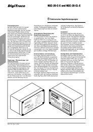
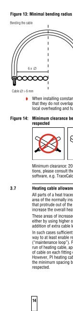
Figure 13: Minimal bending radius of cables<br />
Bending the cable<br />
Cable ∅ > 6 mm<br />
6 x ∅ 2,5 x ∅<br />
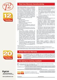
D When installing constant wattage heating cables, ensure<br />
that they do not overlap or cross. Doing so may lead to<br />
local overheating <strong>and</strong> hazard of fire.<br />
Figure 14: Minimum clearance between heating cables must be<br />
respected<br />
Minimum clearance: 20 mm. For hazardous area applications,<br />
please consult the <strong>Tyco</strong> <strong>Thermal</strong> Controls design<br />
software, e.g. TraceCalc Pro.<br />
3.7 Heating cable allowances<br />
All parts of a heat traced system that increase the surface<br />
area of the normally insulated pipe/ vessel or metallic fins<br />
that protrude out of the insulation (e.g. supports), will<br />
increase the overall heatloss.<br />
These areas of increased heat loss require compensation,<br />
either by using higher overall design safety factors or by the<br />
addition of extra cable length.<br />
In such cases sufficient cable should be added in such a<br />
way to at least enable removal of instruments, valves etc<br />
(“maintenance loop”). For pipes requiring more than one<br />
run of heating cable, apply the full allowance for each run<br />
of cable on each fitting or support as long as space allows.<br />
However, PI heating cables must not touch or overlap <strong>and</strong><br />
the minimum spacing between the heating cables must be<br />
respected.<br />
14<br />
Cable ∅ ≤ 6 mm