Installation, Maintenance and Operation Manual - Tyco Thermal ...
Installation, Maintenance and Operation Manual - Tyco Thermal ...
Installation, Maintenance and Operation Manual - Tyco Thermal ...

You also want an ePaper? Increase the reach of your titles
YUMPU automatically turns print PDFs into web optimized ePapers that Google loves.
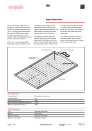
<strong>Installation</strong>, <strong>Maintenance</strong><br />
<strong>and</strong> <strong>Operation</strong> <strong>Manual</strong><br />
Polymer Insulated (PI)<br />
Series Constant Wattage<br />
Heating Cable Systems
1<br />
2<br />
3<br />
4<br />
5<br />
6<br />
7<br />
8<br />
9<br />
10<br />
General information Pg. 4<br />
Heating cable selection <strong>and</strong> storage Pg. 6<br />
Heating cable installation Pg. 7<br />
Components selection <strong>and</strong> installation Pg. 15<br />
Temperature controlling <strong>and</strong> limitation Pg. 16<br />
<strong>Thermal</strong> insulation <strong>and</strong> marking Pg. 18<br />
Power supply <strong>and</strong> electrical protection Pg. 20<br />
System testing Pg. 21<br />
<strong>Operation</strong>, maintenance <strong>and</strong> pipe repairs Pg. 22<br />
Trouble Shooting Pg. 23<br />
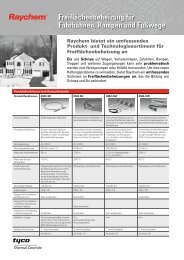
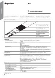
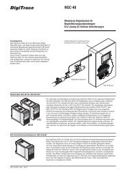
PI heating cable<br />
Splice kit<br />
Junction box<br />
Circuit identification label<br />
PI cold lead cable<br />
Insulation entry kit<br />
2 3<br />
Connection kit with one heating cable<br />
Typical set up of PI-heating cable circuit
1<br />
General information<br />
Use of the manual<br />
The <strong>Installation</strong> <strong>and</strong> <strong>Maintenance</strong> manual is for <strong>Tyco</strong><br />
<strong>Thermal</strong> Controls series resistance heating cable systems<br />
on thermally insulated pipes, vessels <strong>and</strong> associated equipment<br />
only. In particular it refers to polymer insulated (PI)<br />
series heating cable systems, which feature a specific<br />
power output, varying with design parameters, mostly with<br />
cable length <strong>and</strong> voltage. This manual provides general<br />
information <strong>and</strong> shows an overview of the most common<br />
installations <strong>and</strong> applications on PI. In any case, the<br />
information provided for specific projects will take precedence<br />
over this manual.<br />
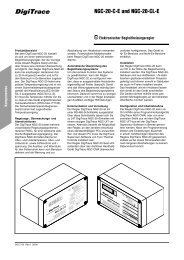
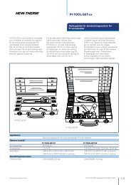
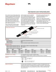
Figure 1: Typical cable construction<br />
Refer to applicable product datasheet for more detailed<br />
information.<br />
Figure 2: Typical heating element set up<br />
Earth leads<br />
Connection leads<br />
For information regarding other applications contact your<br />
<strong>Tyco</strong> <strong>Thermal</strong> Controls representative.<br />
d Important<br />
For the <strong>Tyco</strong> <strong>Thermal</strong> Controls warranty to apply, the<br />
instructions that are included in this manual <strong>and</strong> product<br />
packages must be followed. The installation must also<br />
be in accordance with local National requirements appli-<br />
4<br />
Cable gl<strong>and</strong><br />
Cold leads<br />
Heating cable<br />
Outer jacket PTFE<br />
Protective braid of nickel plated<br />
copper str<strong>and</strong>s (max. 18 Ω/km)<br />
PTFE/high temperature fluoropolymer s<strong>and</strong>wich<br />
High temperature resistance heating conductor<br />
Cable joint between heating cable <strong>and</strong> cold lead
cable to electrical heat tracing systems, as well as the<br />
requirements of other International St<strong>and</strong>ards, such as<br />
IEC 62086.<br />
Personal involved in the installation, testing <strong>and</strong> maintenance<br />
of electric heat tracing systems must be suitably<br />
trained in all special techniques required, as well as in<br />
general electrical installation work. All work should be<br />
monitored by supervisors, experienced in heat tracing applications,<br />
<strong>and</strong> all installations must be carried out using the<br />
appropriate tools as described in the <strong>Tyco</strong> <strong>Thermal</strong> Controls<br />
literature <strong>and</strong> installation instructions.<br />
Area Classification – Ordinary<br />
XPI-NH<br />
Area Classification - Hazardous,<br />
Zone 1 or Zone 2<br />
Special conditions for safe use in hazardous area:<br />
Please refer to relevant Hazardous area certifications<br />
Certificate No. Approvals coding<br />
XPI (system)<br />
PTB 03 ATEX 1218 X II 2 G/D EEx e II T6-T2<br />
XPI (bulk cable)<br />
PTB 05 ATEX 1060 U II G/D EEX e II Tp 260°C<br />
XPI-S (system)<br />
PTB 03 ATEX 1218 X II 2 G/D EEx e II T6-T2<br />
XPI-S (bulk cable)<br />
PTB 05 ATEX 1060U II 2 G/D EEx e II Tp 260°C<br />
Other national approvals:<br />
Please contact <strong>Tyco</strong> <strong>Thermal</strong> Controls<br />
5
2<br />
Heating cable selection <strong>and</strong> storage<br />
The selection of the proper heating cable <strong>and</strong> components,<br />
best suited for the application must be checked against<br />
the relevant product literature <strong>and</strong> the product properties,<br />
of which the most important are summarized in following<br />
table:<br />
Table 1: List of heating cable properties<br />
Heating cable type XPI-NH XPI XPI-S<br />
Maximum voltage U0/U (V AC) 300/500 450/750 450/750<br />
Maximum Withst<strong>and</strong><br />
Temperature (°C)<br />
260 260 260<br />
Short term temperature exposure<br />
(°C)<br />
260 300 300<br />
Temperature Classification n/a T2-T6 T2-T6<br />
Minimum Clearance (mm)(*) 20 20 20<br />
Impact Resistance (J) n/a 4 7<br />
Minimum <strong>Installation</strong><br />
Temperature (°C)<br />
–60 –70 –70<br />
Minimum Bending Radius 2,5 x ∅ 2,5 x ∅ ( ∅< 6mm) 2,5 x ∅ ( ∅< 6mm)<br />
@ –25 °C (mm)<br />
/ 6 x ∅ ( ∅≥ 6mm) / 6 x ∅ ( ∅≥ 6mm)<br />
Minimum Bending Radius 6 x ∅ 2,5 x ∅ ( ∅< 6mm) 2,5 x ∅ ( ∅< 6mm)<br />
@ –60 °C (mm)<br />
/ 6 x ∅ ( ∅≥ 6mm) / 6 x ∅ ( ∅≥ 6mm)<br />
Maximum Power Output (W/m) See table below or use <strong>Tyco</strong> <strong>Thermal</strong> Controls Software<br />
Chemical resistance (*) high high high<br />
(*) - please check against individual datasheet or contact<br />
<strong>Tyco</strong> <strong>Thermal</strong> Controls for further details.<br />
Table 2: Typical cable limits of power output<br />
The typical cable power output is shown above in table 2,<br />
depending on application. The maximum cable power<br />
output is directly dependent on the application <strong>and</strong> control<br />
method used. The actual limits of PI heating cables in a<br />
specific application are given in <strong>Tyco</strong> <strong>Thermal</strong> Controls<br />
Engineering Software (e.g. TraceCalc Pro design software).<br />
Contact <strong>Tyco</strong> <strong>Thermal</strong> Controls for more details.<br />
D Ensure that the heating cable voltage rating is suitable for<br />
the service voltage available <strong>and</strong> that the temperature rating<br />
6<br />
Maintain temperature (°C)<br />
Typ. max. cable load (W/m)<br />
good contact poor contact<br />
≤ 10 30 25<br />
+ 11...30 25 20<br />
+ 31...50 21 18<br />
+ 51...75 18 15<br />
+ 76...100 15 12<br />
+ 101...125 12 10<br />
+ 126...150 10 8<br />
+ 151...200 8 5
3<br />
of the heating cable defined by the design is suited for the<br />
application.<br />
Changing any major design parameters like voltage<br />
or cable length will result in power output other than<br />
designed, which may require a redesign of the entire<br />
system. To prevent overload of the heating cable, fire or<br />
explosion in hazardous areas, verify that the maximum<br />
sheath temperature of the heating cable is below T-class<br />
or auto-ignition temperature of the gases <strong>and</strong>/or dusts<br />
possibly present in those areas. For further information,<br />
see design documentation<br />
(e.g. TraceCalc Pro reports).<br />
Check the design specification to ensure the proper<br />
heating cable is installed on each pipe or vessel.<br />
Refer to <strong>Tyco</strong> <strong>Thermal</strong> Controls product literature to select<br />
an appropriate heating cable for each thermal, chemical,<br />
electrical <strong>and</strong> mechanical environment.<br />
Heating cable storage<br />
D Store the heating cable in a clean, dry place<br />
D Temperature range: –40°C to +60°C<br />
D Protect the heating cable from moisture or mechanical<br />
damage<br />
Heating cable installation<br />
Warning<br />
As with any electrical equipment or wiring installation<br />
that operates at line voltages, damage to heating cable<br />
<strong>and</strong> components, or incorrect installation that allows the<br />
penetration of moisture or contamination can lead to<br />
electrical tracking, arcing <strong>and</strong> potential fire hazard.<br />
Any unconnected heating cable end, exposed to the<br />
environment, must be sealed appropriately.<br />
3.1 Pre-installation checks<br />
Check design recommendations:<br />
D Verify that you have all required engineering documents<br />
supporting the installation.<br />
D Check for any special instructions in engineering documentation<br />
(e.g. fixation method, use of metal mesh etc...).<br />
D Verify that the hazardous area information given in the<br />
engineering documentation is compatible with the area classification<br />
the material will be installed in.<br />
7
Check materials received:<br />
D Inspect heating cable <strong>and</strong> components for in-transit damage.<br />
D Review the heating cable design <strong>and</strong> compare the list of<br />
designed materials to the catalog numbers of heating cables<br />
<strong>and</strong> electrical components received to confirm that proper<br />
materials have been received on site. The heating cable type<br />
<strong>and</strong> hazardous area marking is printed on the outer jacket.<br />
The application related hazardous area details <strong>and</strong> relevant<br />
design data for each individual heating circuit are recorded<br />
on a hazardous area label. (see 7.3)<br />
D Measure <strong>and</strong> note down the electrical resistance <strong>and</strong> the<br />
insulation resistance of the cable. Compare these values to<br />
those in the design documents (see section 8).<br />
Check equipment to be traced:<br />
D Check identification, dimensions of pipework /vessel, actual<br />
temperatures <strong>and</strong> insulation properties against the design<br />
documents.<br />
D Ensure all pressure testing of pipework/vessel is complete<br />
<strong>and</strong> final paint <strong>and</strong> pipe/vessel coatings are dry to touch.<br />
D Walk the system <strong>and</strong> plan the routing of the heating cable<br />
on the pipe, including tracing of heatsinks. e.g. valves,<br />
flanges, supports, drains etc.<br />
D Inspect piping for burrs, rough surfaces, sharp edges etc.<br />
which could damage the heating cable. Smooth off or cover<br />
with layers of glass cloth tape, aluminium foil or rubber<br />
profiles (e.g. G-02).<br />
3.2 Heating cable pulling <strong>and</strong> laying<br />
Heating cable pulling tips:<br />
D Use a reel holder that pays out smoothly with little tension.<br />
Figure 3: Importance of cable pulling direction<br />
3<br />
7<br />
D Avoid distortion of the cable <strong>and</strong> kinking.<br />
D When pulling the heating cable, avoid:<br />
d sharp edges<br />
8
9<br />
d excessive pulling force<br />
d kinking <strong>and</strong> crushing<br />
d walking on it, or running over it with equipment.<br />
D Keep heating cable strung loosely but close to the pipe<br />
being traced, to avoid interference with supports <strong>and</strong> other<br />
equipment.<br />
D Add additional heating cable to trace the fittings,<br />
supports <strong>and</strong> other accessories as required by the design<br />
specification.<br />
D Leave the appropriate amount of heating cable at all power<br />
connection, splice <strong>and</strong> tee locations. (Refer to component<br />
installation instructions)<br />
D Pay out designed length <strong>and</strong> mark (i.e. with fixing tape) on<br />
cable while remainder of cable still on reel (XPI: use printed<br />
metermarks for orientation).<br />
3.3 Heating cable attachment<br />
d Do not use metal b<strong>and</strong>ings, tie wire, vinyl electrical tape<br />
or duct tape, as heating cable damage may result. Fix<br />
in place with a minimum of two wraps of the appropriate<br />
self-adhesive glass cloth tape, metal mesh or fixing strip at<br />
300 mm intervals <strong>and</strong> additionally where necessary. Other<br />
attachments (like aluminium tape) may be specified in the<br />
design documentation.<br />
D Cable must be installed <strong>and</strong> fixed as such, that movement<br />
of cable during its heating up cycles is permitted, but not<br />
to allow the cable to move freely under its own weight.<br />
The heating cables may be installed in straight, multiple<br />
runs as required by the design specification<br />
D On horizontal pipes fix on lower quadrant as shown below<br />
<strong>and</strong> not on bottom of pipe.<br />
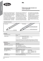
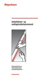
Figure 4: Cable orientation on pipe<br />
Pipe<br />
Sensor<br />
Pipe<br />
Sensor<br />
Heating cable Heating cable<br />
Read the design documents, in particular concerning the<br />
need for cable allowances <strong>and</strong> regard the location of junction<br />
boxes/ controllers before permanently attaching the<br />
cable to the pipe.<br />
D <strong>Installation</strong> on tanks might require additional fixation devices<br />
as prepunched steel strips as shown on the next page:
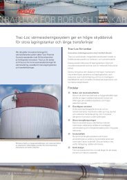
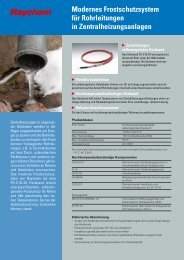
Figure 5: Typical cable layout on bigger surfaces as tank walls<br />
Prepunched<br />
strapping<br />
Temperature<br />
sensor<br />
Temperature<br />
controller<br />
Figure 6: Fixation device: prepunched steel strap<br />
D Use insulation entry kits, where cable penetrates the metallic<br />
insulation cladding by design. In all other places, where<br />
cable passes through metal sheet like cladding front disks<br />
(e.g. on valves) protective rubber profiles G-02 should be<br />
used to mechanically protect the cable.<br />
3.4 Cutting the heating cable<br />
D Before cutting it, confirm the minimum required length <strong>and</strong><br />
tracing allowances.<br />
D Any change to designed circuit length will change power<br />
output <strong>and</strong> design must be reconfirmed.<br />
D Cut the heating cable to length after it is attached to the<br />
pipe.<br />
10<br />
Cold leads<br />
Heating cable<br />
Junction<br />
box
3.5 Attachment tapes<br />
GT-66 Glass cloth tape for attaching heating cable to pipe.<br />
Not for stainless-steel pipes or for installation temperatures<br />
below 5°C.<br />
GS-54 Glass cloth tape for attaching heating cable to pipe.<br />
For stainless-steel pipes or for any installation below 5°C.<br />
ATE-180 Aluminium tape for attaching the cable to vessels.<br />
For all surfaces <strong>and</strong> installations above 0°C.<br />
D At long straight lengths, expansion loops may be needed to<br />
allow for thermal expansion of the pipe without exposing<br />
cable to excess of strain. Other attachment methods could<br />
be specified. In that case, please refer to the design documentation.<br />
3.6 Typical installation details<br />
D Typical installation details for fixing heating cable to pipe fittings<br />
are shown hereafter.<br />
Figure 7: Typical cable allowance on pipe shoe<br />
PI heating cable<br />
Pi heating cables must not be overlapped <strong>and</strong> the minimum<br />
clearance must be respected. Refer to the design documentation<br />
for more info or contact <strong>Tyco</strong> <strong>Thermal</strong> Controls for<br />
assistance.<br />
Figure 8: Typical cable allowance on valve<br />
11<br />
See design documentation<br />
for specific heating cable<br />
length needed<br />
Pipe
Pi heating cables must not be overlapped <strong>and</strong> the minimum<br />
clearance must be respected. Refer to the design documentation<br />
for more info or contact <strong>Tyco</strong> <strong>Thermal</strong> Controls for<br />
assistance.<br />
Figure 9: Typical cable routing on pipe elbows<br />
Figure 10: Typical cable routing on flanges<br />
Pi heating cables must not be overlapped <strong>and</strong> the minimum<br />
clearance must be respected. Refer to the design documentation<br />
for more info or contact <strong>Tyco</strong> <strong>Thermal</strong> Controls for<br />
assistance.<br />
General note:<br />
D Trace pipe fittings as shown to allow easy maintenance.<br />
Alternatively wire mesh cages might be used.<br />
12<br />
PI heating cable<br />
Glass tape<br />
Pipe<br />
Apply glass tape to hold<br />
heating cable in place<br />
Glass tape (every 0,3 m)<br />
PI heating cable is applied to<br />
outside radius of elbow<br />
Flange<br />
Heating cable
Figure 11-12: Cable applied on wire mesh<br />
D Consult the design specification for the heat tracing requirements<br />
for fittings <strong>and</strong> supports.<br />
D Follow the instructions for cutting <strong>and</strong> stripping of heating<br />
cables; they are included in the individual component installation<br />
instructions.<br />
D The heating cable’s minimum bend radius must be respected<br />
(refer to Table 1), together with the minimum clearance.<br />
Refer to the design documentation for more info or contact<br />
<strong>Tyco</strong> <strong>Thermal</strong> Controls for assistance.<br />
13
Figure 13: Minimal bending radius of cables<br />
Bending the cable<br />
Cable ∅ > 6 mm<br />
6 x ∅ 2,5 x ∅<br />
D When installing constant wattage heating cables, ensure<br />
that they do not overlap or cross. Doing so may lead to<br />
local overheating <strong>and</strong> hazard of fire.<br />
Figure 14: Minimum clearance between heating cables must be<br />
respected<br />
Minimum clearance: 20 mm. For hazardous area applications,<br />
please consult the <strong>Tyco</strong> <strong>Thermal</strong> Controls design<br />
software, e.g. TraceCalc Pro.<br />
3.7 Heating cable allowances<br />
All parts of a heat traced system that increase the surface<br />
area of the normally insulated pipe/ vessel or metallic fins<br />
that protrude out of the insulation (e.g. supports), will<br />
increase the overall heatloss.<br />
These areas of increased heat loss require compensation,<br />
either by using higher overall design safety factors or by the<br />
addition of extra cable length.<br />
In such cases sufficient cable should be added in such a<br />
way to at least enable removal of instruments, valves etc<br />
(“maintenance loop”). For pipes requiring more than one<br />
run of heating cable, apply the full allowance for each run<br />
of cable on each fitting or support as long as space allows.<br />
However, PI heating cables must not touch or overlap <strong>and</strong><br />
the minimum spacing between the heating cables must be<br />
respected.<br />
14<br />
Cable ∅ ≤ 6 mm
4<br />
For some applications, it may be physically impossible to<br />
install all of the recommended allowance directly on the<br />
fitting or support. In this case, install the excess heating<br />
cable on the pipe on either side of the fitting or support,<br />
or distribute the additional heater length along the entire<br />
circuit length if a lower local temperature is acceptable. If<br />
required, contact <strong>Tyco</strong> <strong>Thermal</strong> Controls for assistance.<br />
For further details on individual allowances please refer to<br />
the design documentation or the <strong>Tyco</strong> <strong>Thermal</strong> Controls<br />
design software (e.g. TraceCalc Pro reports).<br />
Components selection <strong>and</strong><br />
installation<br />
General notes:<br />
Use the Design Specification to select required<br />
components.<br />
<strong>Tyco</strong> <strong>Thermal</strong> Controls component kits must be used to<br />
satisfy St<strong>and</strong>ards <strong>and</strong> Approval Body requirements <strong>and</strong> the<br />
<strong>Tyco</strong> <strong>Thermal</strong> Controls warranty to apply.<br />
<strong>Installation</strong> instructions included in the kit must be<br />
followed, including those for preparation of the heating<br />
cable connections.<br />
Before assembly, use the guide given in the instructions,<br />
to ensure that the kit is correct for the heating cable <strong>and</strong><br />
environment.<br />
4.1 Components required<br />
D For installation of all components refer to the relevant<br />
component installation instructions.<br />
D Required for each heating cable end: Cold lead connection<br />
<strong>and</strong> insulation entry kit<br />
D As required: Splice kits <strong>and</strong> accessories (fixing tape, support<br />
brackets, pipe straps, labels, etc)<br />
4.2 Component installation hints<br />
D On horizontal pipes locate junction boxes below pipe<br />
wherever possible.<br />
D Locate junction boxes for easy access, but not exposed to<br />
mechanical abuse.<br />
D Try to position junction boxes such, that power cable <strong>and</strong><br />
heating cable entries point downwards, to minimize water<br />
ingress in the insulation.<br />
15
D Confirm junction box gl<strong>and</strong>s <strong>and</strong> stopping plugs are correct<br />
for application <strong>and</strong> fixed firmly in place.<br />
D Route heating cable between junction box <strong>and</strong> place where<br />
it enters the insulation cladding such, that the risk of<br />
mechanical damage is minimized.<br />
d Do not strain heating cable as it exits/enters junction boxes<br />
<strong>and</strong> insulation entries.<br />
D Ensure heating cable is fixed over pipe straps such as<br />
used for junction box support brackets to avoid potential<br />
mechanical damage.<br />
Figure 15: Cable layout over clamps <strong>and</strong> straps<br />
5<br />
D Cable joints (splices) should be placed only in places,<br />
where cable is not bent or mechanically stressed.<br />
Temperature control <strong>and</strong><br />
limitation<br />
5.1 General rules<br />
<strong>Tyco</strong> <strong>Thermal</strong> Controls PI series heating cables are constant<br />
power output heaters <strong>and</strong> as such typically require<br />
temperature control, unless otherwise explicitely specified.<br />
Good practice <strong>and</strong> local regulations may require additionally<br />
independent temperature limitation devices. The selection<br />
of such devices also depends on environmental conditions<br />
(non-haz. or haz. area)<br />
D For applications in hazardous areas either a stabilised<br />
design or a thermostat control with temperature limiter<br />
complying with the requirements of clause 5.8.10 of<br />
EN 50019: 2000 (or EN 60079-30-1) can be used to limit<br />
the surface temperature of the heating cable.<br />
16<br />
Pipe<br />
Bar hanger<br />
glass tape
D In cases where stabilised design is not applied, a control<br />
thermostat ensures that under normal conditions, the heating<br />
system will be switched off, as soon as maintain temperature<br />
is reached.<br />
An additional, independent temperature limiter ensures<br />
that if the control thermostat fails, the surface temperature<br />
of the heating cable will not exceed the maximum allowed<br />
temperature for hazardous area by switching off the heating<br />
cable.<br />
General features of such a limiting device:<br />
d A lockout function ensures that the heating cable remains<br />
switched off, until failure has been eliminated <strong>and</strong> normal<br />
conditions are restored.<br />
The lockout function is manually re-armed. Reset<br />
requires a tool (e.g. a key to open a panel or a password<br />
for software).<br />
d Value of setpoint has to be secured against unintended<br />
change.<br />
d Limiter must permanently switch off in case of sensor<br />
malfunction.<br />
d The limiter function is tested against relevant st<strong>and</strong>ards<br />
(e.g. EN60730 or DIN3440 etc.).<br />
D Follow the installation instructions supplied with the thermostat<br />
<strong>and</strong>/or the limiter.<br />
D Use a proper wiring diagram for the heating cable layout<br />
<strong>and</strong> control method desired.<br />
D The limiter must be set to ensure that the maximum<br />
temperature of the surface of the cable does not exceed<br />
neither T-class nor maximum working temperature of the<br />
heater for a given output under worse case conditions.<br />
d Warning<br />
As with any temperature measurement equipment, possible<br />
falsification of true temperatures due to increased<br />
heatloss caused by the sensor itself might lead to inaccurate<br />
temperature readings or unsafe tripping of safety<br />
limiters. The setpoint might need to be adjusted<br />
accordingly<br />
Contact <strong>Tyco</strong> <strong>Thermal</strong> Controls or the supplier of the<br />
limitation device in order to obtain detailed information<br />
concerning offsetting of limitation devices.<br />
5.2 Sensor placement: Temperature control device<br />
The choice of the right location for the controller sensor<br />
depends on, but is not limited to following aspects:<br />
D Flow direction of the fluid, best location: downstream.<br />
D Impact of heatsinks such as supports etc, best: close to<br />
heatsink.<br />
17
D Chimney effect on large size vertical pipes, best: on the<br />
bottom.<br />
D Accessibility for maintenance purposes, best: at ground<br />
level.<br />
D Impact of other heat sources, sun etc, best: at cold side.<br />
For details please refer to the engineering documentation.<br />
5.3 Sensor placement: limitation device<br />
6<br />
Typically the sensor is being placed on a length of cable,<br />
that is separated from the pipe by means of insulating<br />
material,in order to create an “artificial hotspot”.<br />
The choice of the right location for the limiter sensor<br />
depends on, but is not limited to following aspects:<br />
D Flow direction of the fluid, best location: upstream.<br />
D Impact of heatsinks such as supports etc, best: away from<br />
heatsinks.<br />
D Accessability for maintenance purposes, best: at ground<br />
level.<br />
D Chimney effect on large size vertical pipes, best: at the top.<br />
D Impact of other heat sources, sun etc, best: at hot side of<br />
pipe.<br />
D It is the responsibility of the installer to ensure that these<br />
conditions are met in the most appropriate way.<br />
For details please refer to the engineering documentation.<br />
<strong>Thermal</strong> insulation <strong>and</strong> marking<br />
6.1 Pre-insulation checks<br />
D Visually inspect the heating cable <strong>and</strong> components for correct<br />
installation <strong>and</strong> possible damage. (See Section 10 if<br />
damaged.)<br />
D Insulation resistance testing (as per Section 8) is strongly<br />
recommended prior to covering the pipe with thermal insulation.<br />
18
6.2 Insulation related requirements<br />
D Correct temperature maintenance requires properly installed<br />
<strong>and</strong> dry thermal insulation.<br />
D Check that all pipework, including fittings, wall penetrations<br />
<strong>and</strong> other areas are completely insulated<br />
D <strong>Thermal</strong>ly insulate <strong>and</strong> weatherproof to design specification.<br />
D Polymeric heating cables need to be protected against<br />
mechanical damage. Metallic insulation cladding is<br />
considered as sufficient mechanical protection.<br />
D Ensure that heating cable is not damaged during installation<br />
of cladding by drills, self tapping screws <strong>and</strong> sharp edges of<br />
cladding etc.<br />
d In all stabilised design cases, the characteristics of the<br />
installed thermal insulation (material <strong>and</strong> thickness)<br />
must comply with the design requirements <strong>and</strong> be<br />
verified <strong>and</strong> confirmed in the documentation, to ensure<br />
compliance with approvals requirements.<br />
d Make sure, that under no circumstances any insulation<br />
material is being placed between heated surface <strong>and</strong><br />
cable, thus disabling intended heat flow to the substrate,<br />
which may result in possible overheating of the cable.<br />
D Good practise requires wrapping of the installed heating<br />
system with an appropriate metal foil prior to installation of<br />
the thermal insulation. This is especially so at places where<br />
intimate contact between trace heating cable <strong>and</strong> heated<br />
surface is not possible, such as valves or flanges where a<br />
suitable heat sink of temperature rated metal foil may be<br />
used.<br />
Details may be described in local insulation st<strong>and</strong>ards.<br />
D Check that all insulation entry kits are fitted correctly or that<br />
other alternative protective devices (such as rubber profiles<br />
G-02) are used, where appropriate.<br />
D Ensure that all places are sealed where thermostat capillaries,<br />
sensor cables or support brackets etc. exit the cladding.<br />
6.3 Marking<br />
D Install "Electric Traced" signs on the insulation cladding<br />
along piping at suitable intervals (3-5 m intervals recommended)<br />
on alternate sides as a warning.<br />
D Mark on outside of insulation the location of any heating<br />
cable components like connection points, splices etc.<br />
19
7<br />
Power supply <strong>and</strong><br />
electrical protection<br />
d Do not energize cable when it is coiled or on the reel.<br />
7.1 Electrical loading<br />
Size overcurrent protective devices according to the design<br />
specification <strong>and</strong>/or local st<strong>and</strong>ard practises.<br />
7.2 Residual current (earth fault) protection<br />
<strong>Tyco</strong> <strong>Thermal</strong> Controls requires the use of a 30 mA<br />
residual current device to provide maximum safety <strong>and</strong> protection.<br />
When design results in a higher leakage current,<br />
a maximum 300 mA RCD may be used. All safety aspects<br />
need to be proven. Also refer to local st<strong>and</strong>ards.<br />
For any heating cables installed in a hazardous area, the use<br />
of residual current devices is m<strong>and</strong>atory by the electrical<br />
codes <strong>and</strong> st<strong>and</strong>ards.<br />
7.3 Circuit marking<br />
For all hazardous area installations make sure, that system<br />
is properly marked with a Haz area label such as<br />
CW-LAB-EX-KIT or PI-LABEL-EX, which needs to be completed<br />
with design data by the responsible installer. Results<br />
of design documentation (TraceCalc Pro) may be used.<br />
20
8<br />
System testing<br />
WARNING: Fire hazard in hazardous locations.<br />
Megger tests can produce sparks. Be sure there are no<br />
flammable vapors in the area before performing this test<br />
(hot work permit).<br />
8.1 Testing of insulation resistance <strong>and</strong> conductor resistance<br />
<strong>Tyco</strong> <strong>Thermal</strong> Controls recommends insulation resistance<br />
test<br />
D before installing heating cable<br />
D before installing thermal insulation<br />
D prior to initial start-up/ after completion of thermal<br />
insulation<br />
D as part of the periodic maintenance. (see Section 9.2).<br />
The heating circuit electrical resistance needs to be measured<br />
<strong>and</strong> compared to the design documentation before<br />
initial startup.<br />
8.2 Test method for insulation resistance testing<br />
After completing heating cable installation, the insulation<br />
resistance between the conductor <strong>and</strong> the braid has to be<br />
tested (see Section 6.1).<br />
All polymer insulated heating cables: using a testing<br />
voltage of 2500 Vdc.<br />
Minimum readings should be 20 MΩ regardless of the<br />
heating cable length.<br />
The installer should record the values for each circuit<br />
on the installation record sheet.<br />
Tip: Discharge heating cable before disconnecting from the<br />
Megger<br />
21
9<br />
<strong>Operation</strong>, maintenance <strong>and</strong><br />
pipe repairs<br />
WARNING: Heating cables are capable of reaching<br />
high temperatures during operation <strong>and</strong> can cause burns<br />
when touched. Avoid contact when cables are powered.<br />
Insulate the pipe before energizing the cable. All work<br />
needs to be carried out by properly trained personnel.<br />
9.1 Heating cable operation<br />
d Temperature exposure of the cable must be within the<br />
range specified in the product literature. Exceeding the<br />
limitations will shorten the service life <strong>and</strong> may<br />
permanently damage the heating cable.<br />
D Pipe insulation must be complete <strong>and</strong> dry to maintain the<br />
required temperature.<br />
9.2 Inspection <strong>and</strong> maintenance<br />
D Visual inspection: exposed heating cable should be checked<br />
periodically to make sure that no mechanical damage has<br />
occured.<br />
D Insulation resistance testing: The system should be tested<br />
regularly. Check in advance, whether hazardous area<br />
conditions allow insulation resistance testing. A hot work<br />
permit might be required.<br />
D When measuring the insulation resistance from the main<br />
supply panel, the test is performed between L <strong>and</strong> PE.<br />
Optional testing could be performed between braid <strong>and</strong><br />
pipe (disconnect heating cable ends).<br />
D Functionality test of electrical protection: Circuit breaker<br />
<strong>and</strong> residual current device should be tested at least once a<br />
year or according to manufacturer’s instructions.<br />
D Functionality test of temperature control systems:<br />
Depending on how essential temperature control is<br />
regarding process requirements <strong>and</strong> how critical temperature<br />
limitation is for fulfillment of hazardous area requirements,<br />
tests should be carried out at regular intervals.<br />
D The <strong>Installation</strong> Record Sheet on the following pages<br />
should be completed during maintenance of each circuit in<br />
your system.<br />
Freeze protection systems should be tested before the<br />
winter months each year (see section 8).<br />
Temperature maintenance systems should be tested at<br />
least twice a year.<br />
22
9.3 Piping systems repair <strong>and</strong> maintenance<br />
10<br />
D Isolate heating cable circuit <strong>and</strong> protect the heating cable<br />
from mechanical or thermal damage during pipe repair<br />
work.<br />
D Check heating cable installation after pipe repairs <strong>and</strong><br />
make sure that thermal insulation is restored according to<br />
the recommendations in Section 6. Check correct functioning<br />
of all relevant electrical protection systems.<br />
Trouble Shooting<br />
WARNING: Damage to cables or components can<br />
cause sustained electrical arcing or fire. Do not energize<br />
heating cables that have been damaged. Damaged<br />
heating cable, splices or connections must be repaired or<br />
replaced. Damaged cable should be repaired by a qualified<br />
person.<br />
D It should be carefully evaluated, whether the severity of the<br />
damage allows on-site repair or whether the entire<br />
heating cable needs to be replaced.<br />
Also refer to the Troubleshooting guide on the following<br />
pages. If the problem persists after following the guidelines,<br />
contact <strong>Tyco</strong> <strong>Thermal</strong> Controls.<br />
23
24 25 26<br />
MONOPHASED INSTALLATION RECORD SHEET<br />
Date:<br />
<strong>Installation</strong> company: Installer:<br />
Project / Site name:<br />
Area name:<br />
Average pipe temperature when measuring loop resistance: °C<br />
1 Visual inspection<br />
Heating circuit no.:<br />
P & ID -no.:<br />
Drawing no.:<br />
Panel/Circuit breaker no.:<br />
Cable type:<br />
Total Cable length (m): m<br />
Required value Actual value Signature<br />
1a Minimal allowed spacing mm* mm<br />
1b Minimal bending radius mm* mm<br />
1c Temperature sensor properly installed on the pipe/vessel & control temperature is set yes:<br />
1d Sensor of temperature limiter properly installed <strong>and</strong> set according to design specification yes:<br />
2 Before commencing of thermal insulation works<br />
2a Insulation resistance test voltage (V dc) ≥ 2500 Vdc Vdc<br />
2b Insulation resistance of cable > 20 MΩ MΩ<br />
2c Cable resistance: Ω Ω<br />
2d Cable covered with aluminium foil at flanges & cable on valves with wire mesh cages yes:<br />
3 After finalization of thermal insulation works<br />
3a Cables entries are sealed <strong>and</strong> cable protected at entries into insulation cladding yes:<br />
3b <strong>Thermal</strong> insulation material meets design requirements * yes:<br />
3c <strong>Thermal</strong> insulation thickness meets design requirements mm* yes:<br />
3d Warning labels installed on cladding every 5 m/ at components yes:<br />
3e Insulation resistance test voltage (Vdc) ≥ 2500 Vdc Vdc<br />
3f Insulation resistance of cable > 20 MΩ MΩ<br />
4 Prior to energizing of the cable<br />
4a Circuit feeding box marked properly yes:<br />
4b Control temperature set to setpoint °C* °C<br />
4c Limiter set to trip value <strong>and</strong> protected against damages °C* °C<br />
4d Insulation resistance test voltage (Vdc) ≥ 2500 Vdc Vdc<br />
4e Insulation resistance at commissioning of cable > 20 MΩ MΩ<br />
4f Circuit voltage at feeding box Vac L-N* Vac L-N<br />
Remarks: (fill in what is applicable)<br />
(*1) Value to be taken from design documentation.<br />
General note: Local / national rules <strong>and</strong> st<strong>and</strong>ards need to be respected where applicable.<br />
Vac L-L* Vac L-L
27 28 29<br />
TRIPHASED INSTALLATION RECORD SHEET<br />
Date:<br />
<strong>Installation</strong> company: Installer:<br />
Project / Site name:<br />
Area name:<br />
Average pipe temperature when measuring loop resistance: °C<br />
1 Visual inspection<br />
Heating circuit no.:<br />
P & ID -no.:<br />
Drawing no.:<br />
Panel/Circuit breaker no.:<br />
Cable type:<br />
Cable length first segment: m<br />
Cable length second segment: m<br />
Cable length third segment: m<br />
Configured in: DELTA / STAR (cross out what is not applicable)<br />
Required value Actual value Signature<br />
1a Minimal allowed spacing mm* mm<br />
1b Minimal bending radius mm* mm<br />
Temperature sensor properly installed on the pipe/vessel & control temperature is set yes:<br />
Sensor of temperature limiter properly installed <strong>and</strong> set according to design specification yes:<br />
2 Before commencing of thermal insulation works<br />
2a Insulation resistance test voltage (Vdc) ≥ 2500 Vdc Vdc<br />
2b Insulation resistance segment 1 > 20 MΩ MΩ<br />
Insulation resistance segment 1 > 20 MΩ MΩ<br />
Insulation resistance segment 1 > 20 MΩ MΩ<br />
2c Segment 1 resistance: Ω* Ω<br />
Segment 2 resistance: Ω* Ω<br />
Segment 3 resistance: Ω* Ω<br />
2d Cable covered with aluminium foil at flanges & cable on valves with wire mesh cages yes:<br />
3 After finalization of thermal insulation works<br />
3a Cables entries are sealed <strong>and</strong> cable protected at entries into insulation cladding yes:<br />
3b <strong>Thermal</strong> insulation material meets design requirements * yes:<br />
3c <strong>Thermal</strong> insulation thickness meets design requirements mm* yes:<br />
3d Warning labels installed on cladding every 5 m/ at components yes:<br />
3e Insulation resistance test voltage (Vdc) ≥ 2500 Vdc Vdc<br />
3f Insulation resistance segment 1 > 20 MΩ MΩ<br />
Insulation resistance segment 1 > 20 MΩ MΩ<br />
Insulation resistance segment 1 > 20 MΩ MΩ<br />
4 Prior to energizing of the cable<br />
4a Circuit feeding box marked properly yes:<br />
4b Control temperature set to setpoint °C* °C<br />
4c Limiter set to trip value <strong>and</strong> protected against damages °C* °C<br />
4d Insulation resistance test voltage (Vdc) ≥ 2500 Vdc Vdc<br />
4e Insulation resistance at commissioning segment 1 > 20 MΩ MΩ<br />
Insulation resistance at commissioning segment 1 > 20 MΩ MΩ<br />
Insulation resistance at commissioning segment 1 > 20 MΩ MΩ<br />
4f Circuit voltage at feeding box 3 x Vac L-N* 3 x Vac L-N<br />
Remarks: (fill in what is applicable)<br />
(*1) Value to be taken from design documentation.<br />
General note: Local / national rules <strong>and</strong> st<strong>and</strong>ards need to be respected where applicable.<br />
3 x Vac L-N* 3 x Vac L-N<br />
Vac L-L* Vac L-L
Trouble Shooting Guide<br />
A Symptom: Overcurrent protection trips.<br />
Probable Causes<br />
1 Electrical fault at:<br />
a damaged heating cable<br />
b faulty splices<br />
c cold lead connections<br />
2 Circuit oversized<br />
3 Defective electrical protection<br />
4 Start-up below minimum design temperature<br />
(copper conductor only)<br />
B Symptom: RCD trips.<br />
Probable Causes<br />
1 Earth fault at:<br />
a damaged heating cable<br />
b faulty splices<br />
c cold lead connections<br />
2 Excessive moisture in:<br />
a junction boxes<br />
b splices <strong>and</strong> cold lead connections<br />
3 High leakage currents due to a combination of excessive<br />
lengths of power cable <strong>and</strong> heating cable.<br />
4 Defective RCD<br />
5 Mains borne disturbances<br />
30 31<br />
Corrective actions<br />
1 Investigate <strong>and</strong> remedy<br />
2 Resize or redesign<br />
3 Replace<br />
4 a redesign for lower startup temperatures.<br />
b preheat pipe from alternative heat source to<br />
temperatures considered in electrical design<br />
c employ soft start techniques of control system to<br />
smoothly heat up system.<br />
Corrective actions<br />
1 Investigate <strong>and</strong> remedy<br />
2 Dry out <strong>and</strong> reseal or remake immediately <strong>and</strong><br />
perform insulation resistance test.<br />
3 Redesign<br />
4 Replace<br />
5 Redesign distribution
C Symptom: No power output.<br />
Probable Causes<br />
1 Temperature limiter is tripped<br />
2 Loss of supply voltage due to:<br />
a overcurrent protection or residual current protection<br />
operating<br />
b loose terminals in junction box, bad splice<br />
c loss of supply cable continuity (open circuited from damage)<br />
3 Temperature controller defect<br />
D Symptom: Low pipe temperature.<br />
Probable Causes<br />
1 Wet thermal insulation<br />
2 Incorrect setting or operation of temperature controls e.g.,<br />
thermostats.<br />
3 Design error<br />
Note:<br />
Locate faults by the following steps:<br />
1 Visually inspect the power connections <strong>and</strong> splices for correct<br />
installation.<br />
2 Look for signs of damage at:<br />
a) Valves, pumps, flanges <strong>and</strong> supports.<br />
b) Areas where repairs or maintenance work has been carried out<br />
recently.<br />
3 Look for crushed or damaged insulation <strong>and</strong> cladding along the pipe.<br />
32 33<br />
Corrective Actions<br />
1 Investigate causes, restore normal conditions <strong>and</strong> re-arm<br />
2 Restore supply voltage<br />
a following A <strong>and</strong> B<br />
b re-tighten terminals, replace splice connection<br />
NB: If excessive heating has occured due to high<br />
resistance, replace terminals or crimps<br />
c locate damage <strong>and</strong> repair<br />
3 Investigate causes, replace equipment<br />
Corrective Actions<br />
1 Remove <strong>and</strong> replace with dry insulation of correct<br />
specification <strong>and</strong> ensure complete weatherproofing<br />
2 Repair or reset to correct level of operation<br />
3 Check with competent authority for design conditions <strong>and</strong><br />
modify to meet <strong>Tyco</strong> <strong>Thermal</strong> Controls recommendations<br />
4 If after 1, 2 <strong>and</strong> 3 above the fault has not been located,<br />
then either:<br />
a) Consult <strong>Tyco</strong> <strong>Thermal</strong> Controls for further assistance.<br />
b) Where local practices <strong>and</strong> conditions allow (e.g., non-hazardous<br />
areas) isolate one section of heating cable from another by cutting in<br />
half <strong>and</strong> testing (e.g., insulation resistance) both halves until<br />
general area of damage is found.<br />
Remove insulation <strong>and</strong> expose fault.
HEW-THERM is a trademark of <strong>Tyco</strong> <strong>Thermal</strong> Controls, LLC or its affiliates<br />
All of the above information, including illustrations, is believed to be re li a ble. Users how ev er, should independently evaluate<br />
the suit a bil i ty of each product for their ap pli ca tion. <strong>Tyco</strong> <strong>Thermal</strong> Controls makes no warranties as to the accuracy or<br />
completeness of the in for ma tion <strong>and</strong> disclaims any liability re gard ing its use. <strong>Tyco</strong> <strong>Thermal</strong> Controls’s only ob li ga tions are<br />
those in the St<strong>and</strong> ard Terms <strong>and</strong> Conditions of Sale for this product <strong>and</strong> in no case will <strong>Tyco</strong> <strong>Thermal</strong> Controls be liable for<br />
any incidental, indirect or con se quen tial dam ag es arising from the sale, re sale, use or misuse of the product. <strong>Tyco</strong> <strong>Thermal</strong><br />
Controls Spec i fi ca tions are subject to change without notice. In addition <strong>Tyco</strong> <strong>Thermal</strong> Controls re serves the right to make<br />
changes in materials or process ing, with out notification to the Buyer, which do not affect com pli ance with any ap pli ca ble<br />
specification.<br />
European Headquarters<br />
<strong>Tyco</strong> <strong>Thermal</strong> Controls<br />
Romeinse Straat 14<br />
3001 Leuven<br />
Belgium<br />
Tel. (32) 16 213 511<br />
Fax (32) 16 213 610<br />
info@tycothermal.com<br />
België / Belgique<br />
<strong>Tyco</strong> <strong>Thermal</strong> Controls<br />
Romeinse Straat 14<br />
3001 Leuven<br />
Belgium<br />
Tel. (32) 16 213 511<br />
Fax (32) 16 213 610<br />
Bulgaria<br />
ERZET Engineering<br />
Kompl. Bratja Miladinovi/bl57/vch.4A<br />
BG-8000 Burgas<br />
Tel./fax (56) 86 68 86<br />
Mobile (88) 86 39 903<br />
Fax (UK) +44 8701368787<br />
Çeská Republika<br />
Raychem HTS s.r.o.<br />
Pražská 636<br />
252 41 Dolní Břežany<br />
Tel. 241 911 911<br />
Fax 241 911 100<br />
Danmark<br />
<strong>Tyco</strong> <strong>Thermal</strong> Controls Nordic AB<br />
Flöjelbergsgatan 20B<br />
SE-431 37 Mölndal<br />
Tel. 70 11 04 00<br />
Fax 70 11 04 01<br />
Deutschl<strong>and</strong><br />
<strong>Tyco</strong> <strong>Thermal</strong> Controls GmbH<br />
Birlenbacher Strasse 19-21<br />
57078 Siegen-Geisweid<br />
Tel. (0271) 35600-0<br />
Fax (0271) 35600-28<br />
salesDE@tycothermal.com<br />
España<br />
<strong>Tyco</strong> <strong>Thermal</strong> Controls N.V.<br />
Ctra. De la Coruña, km. 23,500<br />
Edificio ECU I<br />
28290 Las Rozas, Madrid<br />
Tel. (902) 125 307<br />
Fax (91) 640 29 90<br />
France<br />
<strong>Tyco</strong> <strong>Thermal</strong> Controls SAS<br />
B.P. 90738<br />
95004 Cergy-Pontoise Cedex<br />
Tél. 0800 906045<br />
Fax 0800 906003<br />
salesFR@tycothermal.com<br />
Hrvatska<br />
ELGRI d.o.o.<br />
S. Mihalica 2<br />
10000 Zagreb<br />
Tel. (1) 6050188<br />
Fax (1) 6050187<br />
Italia<br />
<strong>Tyco</strong> <strong>Thermal</strong> Controls SPA<br />
Centro Direzionale Milanofiori<br />
Palazzo F1<br />
20090 Assago, Milano<br />
Tel. 02 5776151<br />
Fax 02 577615528<br />
Lietuva/Latvija/Eesti<br />
<strong>Tyco</strong> <strong>Thermal</strong> Controls BV Atstovybe<br />
Smolensko g. 6<br />
LT-03201 Vilnius<br />
Tel. +370 5 2136633<br />
Fax +370 5 2330084<br />
Magyarország<br />
Szarka Ignác<br />
Maroshévísz u. 8<br />
1173 Budapest<br />
Tel. (1) 253 76 17<br />
Fax (1) 253 76 18<br />
Nederl<strong>and</strong><br />
<strong>Tyco</strong> <strong>Thermal</strong> Controls b.v.<br />
Van Heuven Goedhartlaan 121<br />
1181 KK Amstelveen<br />
Tel. 0800 0224978<br />
Fax 0800 0224993<br />
Norge<br />
<strong>Tyco</strong> <strong>Thermal</strong> Controls Norway AS<br />
Postboks 146<br />
1441 Drøbak<br />
Tel. +47 66 81 79 90<br />
Fax +47 66 80 83 92<br />
Österreich<br />
<strong>Tyco</strong> <strong>Thermal</strong> Controls<br />
Division of <strong>Tyco</strong> Fire &<br />
Integrated Solutions GmbH<br />
Office Wien<br />
Brown-Boveri Strasse 6/14<br />
2351 Wiener Neudorf<br />
Tel. (0 22 36) 86 00 77<br />
Fax (0 22 36) 86 00 77-5<br />
Polska<br />
<strong>Tyco</strong> <strong>Thermal</strong> Controls Polska Sp. z o.o.<br />
ul. Cybernetyki 19<br />
02-677 Warszawa<br />
Tel. 0800 800 114<br />
Fax 0800 800 115<br />
Republic of Kazakhstan<br />
<strong>Tyco</strong> <strong>Thermal</strong> Controls<br />
4 Khakimov St.<br />
Atyrau, 060002<br />
Tel. +7 7122 32 56 51<br />
Fax +7 7122 32 56 38<br />
Romania<br />
<strong>Tyco</strong> <strong>Thermal</strong> Controls<br />
Strada Sinaii nr 3<br />
100357 Ploiesti, Prahova<br />
Tel. +40 34 480 21 44<br />
Fax +40 34 480 21 41<br />
РОССИЯ и другие страны СНГ<br />
OOO « Тайко Термал Контролс »<br />
141407, Mосковская обл., г. Химки<br />
ул. Панфилова, 19, 11 этаж,<br />
Деловой Центр Кантри Парк<br />
Тел. +7 (495) 926 18 85<br />
Факс +7 (495) 926 18 86<br />
Serbia <strong>and</strong> Montenegro<br />
Keying d.o.o.<br />
Vuka KaradΩiça 79<br />
23300 Kikinda<br />
Tel. (230) 401 770<br />
Fax (230) 401 790<br />
Schweiz / Suisse<br />
<strong>Tyco</strong> <strong>Thermal</strong> Controls N.V.<br />
Office Baar<br />
Haldenstrasse 5<br />
Postfach 2724<br />
6342 Baar<br />
Tel. (041) 766 30 80<br />
Fax (041) 766 30 81<br />
Suomi<br />
<strong>Tyco</strong> <strong>Thermal</strong> Controls Nordic AB<br />
Flöjelbergsgatan 20B<br />
SE-431 37 Mölndal<br />
Puh. 0800 11 67 99<br />
Telekopio 0800 11 86 74<br />
Sverige<br />
<strong>Tyco</strong> <strong>Thermal</strong> Controls Nordic AB<br />
Kanalvägen 3 A<br />
SE-194 61 Uppl<strong>and</strong>s Väsby<br />
Tel. 08-590 094 60<br />
Fax 08-590 925 70<br />
Türkiye<br />
SAMM Dış Ticaret A.Ş.<br />
Yeniyol Sk. Etap İş Merkezi C<br />
Blok No : 10 Kat : 6<br />
34722 Acıbadem - Kadıköy<br />
İSTANBUL<br />
Tel . +0216-325 61 62 (Pbx)<br />
Faks +0216-325 22 24<br />
United Kingdom<br />
<strong>Tyco</strong> <strong>Thermal</strong> Controls (UK) Ltd<br />
3 Rutherford Road,<br />
Stephenson Industrial Estate<br />
Washington, Tyne & Wear<br />
NE37 3HX<br />
Tel. 0800 969013<br />
Fax 0800 968624<br />
salesUK@tycothermal.com<br />
Worldwide Headquarters<br />
<strong>Tyco</strong> <strong>Thermal</strong> Controls<br />
2415 Bay Road<br />
Redwood City, CA 94063-3032<br />
USA<br />
Tel. (1)(650) 216-1526<br />
Fax (1)(650) 474-7711<br />
info@tycothermal.com<br />
www.tycothermal.com<br />
© 2001 <strong>Tyco</strong> <strong>Thermal</strong> Controls DOC-517 PCN 1244-001034 Rev.4 04/08 Printed in Belgium on chlorine-free bleached paper