SERVICE MANUAL
SERVICE MANUAL
SERVICE MANUAL

Create successful ePaper yourself
Turn your PDF publications into a flip-book with our unique Google optimized e-Paper software.
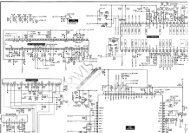
2-3. SERVO SYSTEM Adjustment<br />
2-3-1. RF Switching Position Adjustment<br />
(RP-230 Board)<br />
Purpose:<br />
Adjust the interval between A ch and B ch of tape playback output.<br />
Improve the interchangeability with other tapes and sets.<br />
When it is out of order, the interval appears on the screen, the<br />
screen is disturbed.<br />
Mode PB<br />
Signal Alignment tape SP mode<br />
color bar<br />
Measurement Point CH1: VIDEO LINE OUT<br />
CH2: Pin 2 of CN261 (RP-<br />
230 board) (RF SWP)<br />
Measuring Instrument Oscilloscope<br />
Specified Value 6.5 ± 0.5 H (416 ± 32 µsec)<br />
Adjusting Method:<br />
1) Connect RP-230 board Pin 5 of CN261 to the GND for about<br />
1 secont to activate the RF switching position adjustment mode.<br />
2) Check appear “A P” on FL display.<br />
3) Using the channel + and – buttons, adjust to 416 ± 32 µsec<br />
(6.5 ± 0.5 H).<br />
4) Press the pause button.<br />
CH1<br />
CH2<br />
CH1<br />
CH2<br />
enargement<br />
6.5 ± 0.5 H<br />
(416 ± 32 µsec)<br />
Fig. 7-2-3.<br />
V<br />
Approx. 1 Vp-p<br />
Approx. 5 Vp-p<br />
Vertical sync. signal<br />
7-3<br />
2-4. VIDEO SYSTEM ADJUSTMENT<br />
Adjust the video system in the following sequence as a rule. The<br />
color video signal supplied from the pattern generator is used as a<br />
video input signal for video system adjustment in the recording<br />
mode.<br />
Make sure that sync. and color burst signals meet requirements<br />
specified at set up of adjustment shown in Fig. 7-2-1.<br />
[Adjustment Sequence]<br />
2-4-1. Playback Y Signal Level Check<br />
2-4-2. Recording Chroma Level Check<br />
2-4-3. Sync. AGC Check<br />
2-4-4. X’tal Oscillation Frequency Check<br />
2-4-1. Playback Y Signal Level Check<br />
(MA-315 Board)<br />
Purpose:<br />
Confirm that the playback Y signal level is correct.<br />
Mode PB<br />
Signal Alignment tape SP color bar<br />
Measurement point Pin #• IC201<br />
Measurement equipment Oscilloscope<br />
Specified value 2.10 ± 0.18 Vp-p<br />
Confirmation Method:<br />
1) Confirm that the play Y level is 2.10 ± 0.18 Vp-p.<br />
H<br />
White (100%)<br />
Fig. 7-2-4.<br />
2.10 ± 0.18 Vp-p