Microlino Instruction Manual

Create successful ePaper yourself
Turn your PDF publications into a flip-book with our unique Google optimized e-Paper software.
MICROLINO<br />
INSTRUCTION MANUAL
INTRODUCTION<br />
CONGRATULATIONS ON YOUR MICROLINO!<br />
In 2015, we launched the project with one goal: to<br />
bring a new<br />
product category on the market that could be an alternative<br />
to the car, without much loss of comfort.<br />
We are a family business founded in 1999, which invented<br />
the<br />
first kick-boardscooter as the ideal vehicle for the last<br />
mile.<br />
Often copied, we have always focused on our three<br />
values: quality, sustainability and innovation. The result<br />
is over 50 innovations in the mobility sector, from the<br />
most compact stroller to the <strong>Microlino</strong>.<br />
We hope you enjoy your <strong>Microlino</strong>.<br />
Wim, Merlin und Oliver Ouboter
CONTENTS<br />
SAFETY 4<br />
Safety instructions 4<br />
Special features of the electric vehicle 4<br />
Secure the vehicle against rolling 5<br />
Emergency card 5<br />
Passenger safety 5<br />
Putting on the bench seat belts Child restraint systems 6<br />
Unbuckling the seat belt 6<br />
Child restraint system 6<br />
Safety of the parked vehicle 7<br />
Weight and accessories 7<br />
OPERATION 7<br />
Locking 7<br />
Vehicle key 7<br />
Remote control door 7<br />
Mechanically locking and unlocking the door 8<br />
Tailgate 9<br />
Seat Bench 9<br />
Adjusting the exterior mirrors 10<br />
Windows 10<br />
Sunroof 10<br />
Display of the dashboard 10<br />
Central control element 10<br />
The following functions are available for setting the driver display: 12<br />
Lightning 13<br />
Hazard warning lights 14<br />
USB-ports 15<br />
Charging the 48 V drive battery 15<br />
Charging cable for household sockets (Schuko) 16<br />
Vehicle loaded 17<br />
DRIVING 18<br />
Messages and warnings 19<br />
Handbrake 20<br />
Dial for gear selection 20<br />
State of charge of the drive battery 21<br />
Overheating at maximum continuous load 21<br />
Parking the vehicle 22<br />
MAINTENANCE AND REPAIR 22<br />
Check brake fluid level 22<br />
Backup overview 23<br />
Changing the battery of the remote control 24<br />
Replacing the illuminant 24<br />
Flat tire 24<br />
Lifting points for the vehicle for lifting platform or car jack 24<br />
Care 25<br />
Maintenance interval 25<br />
Parking the vehicle for a longer period of time 25<br />
TECHNICAL DATA 26<br />
WARRANTY 27<br />
Warranty exclusions 28<br />
INDEX 29<br />
3
SAFETY<br />
Safety instructions<br />
In order to draw your attention to situations in which you could endanger yourself and others,<br />
safety instructions are included in this manual aswell as other safety instructions are attached to<br />
the vehicle.<br />
The severity of the danger is shown as follows:<br />
DANGER<br />
Indicates a dangerous situation in which death or serious injury may occur if not<br />
avoided.<br />
Electric motor<br />
The electric motor already has its maximum torque from the beginning. This gives the microlino<br />
a faster acceleration than vehicles with combustion engines of the same power class. Adjust<br />
your driving behaviour accordingly.<br />
Gearbox<br />
The <strong>Microlino</strong> requires neither a conventional gearbox nor a conventional clutch for its electric<br />
motor. The drive has gears similar to those of a conventional automatic transmission.<br />
Driving noise<br />
An electric motor has a very low noise level. Noise that would be generated by a<br />
engine due to the exhaust system, etc., are perceptible when driving. The <strong>Microlino</strong> is also<br />
barely audible from the outside, especially when driving slowly. Bear in mind that other road<br />
users will hardly notice your vehicle acoustically or only at a late stage. Expect unexpected<br />
reactions from pedestrians. Adjust your driving behaviour accordingly.<br />
WARNING<br />
Indicates a dangerous situation that can lead to minor to moderate bodily injury if not<br />
avoided.<br />
IMPORTANT<br />
Indicates a situation in which the product or the environment may be damaged.<br />
Special features of the electric vehicle<br />
Range<br />
The range can vary greatly depending on:<br />
• The driving behaviour<br />
• Charging status<br />
• Number of electrical equipment used (heating, windscreen wipers, etc.)<br />
• Traffic conditions<br />
• Road conditions<br />
• Tyre pressure<br />
• Use of sport mode<br />
• Weather conditions<br />
Always observe the relevant instrument readings and adjust your driving accordingly.<br />
When selecting destinations, plan for local charging local charging possibilities and charging<br />
times.<br />
Compared to vehicles with a combustion engine, the <strong>Microlino</strong> with electric drive has some<br />
noticable differences.<br />
4
Secure the vehicle against rolling<br />
WARNING<br />
If the parking brake is not properly applied when the vehicle is parked, the vehicle may<br />
roll away. This can lead to property damage, traffic accidents and personal injury. Make<br />
sure that the handbrake is always fully applied when you leave the the vehicle. Even on<br />
a downhill slope, the vehicle must be held securely by the handbrake. Before leaving the<br />
vehicle make sure that the handbrake is strong enough to hold the vehicle in position. If necessary,<br />
underlay the wheels with a suitable wedge to prevent the vehicle from rolling away.<br />
IMPORTANT<br />
DANGER<br />
Damaged bench seat belts do not provide adequate protection. Bench belts that are damaged,<br />
worn out or subjected to severe wear and tear increase the risk of serious or fatal<br />
injuries in the event of an accident.<br />
• Regularly check the bench seat belts in the vehicle for damage to the fabric (e.g. cuts,<br />
etc.) and for dirt or rust.<br />
• Regularly check the fastening points and the seat belt buckles for their proper functioning.<br />
• Make sure that the bench seat belts are completely rolled up after use this prevents<br />
soiling and damage.<br />
• Make sure that damaged seat belts or seat belts that have been subjected to a heavy<br />
load in an accident and their anchorage points by a qualified specialist workshop<br />
and replace them if necessary.<br />
• If the seat belt tensioners have been triggered, have the bench seat belts and the<br />
anchorage points checked by a qualified specialist workshop.<br />
When the handbrake is applied, this is indicated visually in the dashboard.<br />
Emergency card<br />
A digital copy of the rescue card is available on the corresponding online platforms.<br />
Passenger safety<br />
The <strong>Microlino</strong> has bench seat belts for all passengers with a seat belt warning system for the<br />
driver. Please note that the <strong>Microlino</strong> does not have safety systems such as airbags, ABS and<br />
ESP and other passive safety features.<br />
Unfastened and incorrectly fastened seat belts increase the risk of serious or fatal injuries in the<br />
event of an accident.<br />
• Wear your bench seat belt correctly every time you drive and make sure, that all other<br />
occupants are wearing their seat belts correctly.<br />
• Never wear a bench seat belt for more than one person at a time.<br />
• Never wear a seat belt around a child sitting on the lap of a passenger.<br />
• Make sure that the seat belts are correctly positioned and that the buckle tongue is in the<br />
correct buckle. Make sure that the seat belt is as tight as possible.<br />
• Remove loose, bulky clothing (e.g. jacket). Do not run the seat belt over objects on your<br />
body (e.g. pens, mobile phones, glasses, etc.).<br />
• Make sure that the seat belt is not twisted or loose.<br />
• Do not make any changes to the bench seat belts and their components.<br />
Observe the following points even if the seat belts are not fastened:<br />
• The bench seat belts must be fully rolled up and not twisted.<br />
• Make sure that the belts, belt guides, belt buckles and other components are not are not<br />
damaged when getting in and out, loading and unloading.<br />
5
Putting on the bench seat belts Child restraint systems<br />
Note that the bench seat belts are for adult vehicle occupants only.<br />
If the bench seat belt locks, this may be due to the following:<br />
• The bench seat belt was pulled out with a jerk.<br />
• The vehicle is on an incline.<br />
• The vehicle is in motion and accelerating or slowing down, going through a curve or on<br />
an incline.<br />
1. Grasp the seat belt by the buckle tongue and guide it slowly and evenly across the<br />
chest and hips.<br />
2. Insert the buckle tongue into the corresponding buckle on the inside of your seat until<br />
you hear it click into place.<br />
3. Make sure that the seat belt is not pinched or twisted and that it does not run over<br />
sharp edges.<br />
Child restraint system<br />
DANGER<br />
Risk of serious or fatal injuries due to improper use of child restraint systems.<br />
Child restraint systems that are not suitable for the vehicle type or are not properly installed<br />
in the vehicle do not provide adequate protection in the event of an accident and increase<br />
the risk of serious or fatal injuries.<br />
Child restraint systems / ISOFIX<br />
The bench seat in your <strong>Microlino</strong> is not designed for child restraint systems because it does<br />
not provide sufficient lateral support.<br />
The bench seats in your <strong>Microlino</strong> are NOT equipped with ISOFIX child restraint<br />
systems.<br />
4. Make sure that the shoulder belt fits snugly against the upper body and runs across<br />
the middle of the shoulder. Adjust your sitting position if necessary.<br />
5. Pull the shoulder belt upwards so that the pelvic belt is tight against your pelvis.<br />
During pregnancy, guide the pelvic belt so that it is as low on the pelvis as possible<br />
and does not press on the abdomen.<br />
6. Make sure that the lap belt remains tightly fastened by repeatedly pulling on the<br />
shoulder belt while driving.<br />
Unbuckling the seat belt<br />
1. Hold the tongue of the seat belt buckle and press the red button on the seat belt<br />
buckle to release the seat belt.<br />
2. Guide the belt by the buckle tongue in the direction of the belt outlet until the belt is<br />
retracted.<br />
Make sure that the belt does not get caught or twisted anywhere.<br />
6
Safety of the parked vehicle<br />
Your <strong>Microlino</strong> is equipped, among other things, with the following devices for the safety of<br />
the parked vehicle:<br />
Radio remote locking<br />
Your <strong>Microlino</strong> is equipped with a radio remote locking system. This allows you to, lock the<br />
door and open the tailgate from the outside.<br />
OPERATION<br />
Locking<br />
Your <strong>Microlino</strong> is locked via the central locking system. To lock the vehicle completely the door<br />
and the tailgate must be closed.<br />
Vehicle key<br />
Press the button on the remote control to unlock the key bit. The key bit is spring-loaded into the<br />
use position and locks when you release the button.<br />
Press and hold the button on the remote control and fold the key manually back to its original<br />
position.<br />
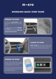
Remote control door<br />
Key for mechanical opening<br />
Emergency release Fig. 1<br />
Emergency release<br />
Should the electronic door opening no longer function, an emergency release is fitted. Pull the<br />
loop and the door will unlock mechanically.<br />
Weight and accessories<br />
This vehicle is designed to carry up to two people and luggage.<br />
Observe the permissible total weight of the vehicle and the permissible axle loads.<br />
The <strong>Microlino</strong> is not intended for use with a trailer.<br />
The <strong>Microlino</strong> is not intended for operation with a roof rack.<br />
The <strong>Microlino</strong> is not designed for towing other vehicles.<br />
Fig.2 Vehicle key<br />
Unlocking button key<br />
Central locking<br />
Opener tailgate<br />
From the outside with the radio remote control unlocking<br />
Unlocking button door and charging socket<br />
To unlock the doors, press the unlock button on the remote control (button 5).<br />
The locking mechanism audibly disengages. The indicator lights flash twice briefly to confirm<br />
unlocking.<br />
7
Locking<br />
Press the locking button on the remote control to lock the doors (button 3). The locking mechanism<br />
audibly engages. The indicator lights flash once to confirm that the doors are locked.<br />
Mechanically locking and unlocking the door (Only if the remote control fails)<br />
From the outside with the key If necessary, press the button on the remote control to open the<br />
key bit (button 2). The lock cylinder is located on the A-pillar at the front right.<br />
Mechanical unlocking<br />
Insert the key into the lock cylinder of the driver‘s door. Press the door lightly against the against<br />
the vehicle during unlocking. Turn the key clockwise at the same time.<br />
Opening the door from the outside<br />
Press the square button under the headlights on the passenger side of the car. This opens the<br />
door by means of the gas strut until it is fully open.<br />
WARNING<br />
Due to slopes, cold temperatures or<br />
other circumstances the door may<br />
open less than a hand. In this case,<br />
do not reach into the the gap, as the<br />
door‘s soft-close mechanism close<br />
mechanism of the door can close the<br />
door again. In such circumstances,<br />
use the protruding metal handle so<br />
that you do not have to reach into the<br />
gap to open the door fully by hand.<br />
Fig.4 Metal handle<br />
Fig.3 Door outside<br />
Opening the door from the inside<br />
Press the switch behind the centre strip of the dashboard. This activates the pop-up spring, and<br />
the door should open a crack so that it opens fully with light pressure.<br />
IMPORTANT<br />
Press the front door lightly against the vehicle to ensure that there is not too much tension on<br />
the lock cylinder. Turn the key in the locking cylinder approx. 90° clockwise. The locking<br />
mechanism audibly unlocks. Fig.3 Door outside<br />
IMPORTANT<br />
It is not possible to drive off with the<br />
door open. The message „Please<br />
close door“ and a red symbol with an<br />
open bonnet is displayed.<br />
8<br />
Fig.5 Door inside
Closing the door from the inside<br />
Pull the front door slowly towards you by the handle strap against the resistance of the spring<br />
up to the seal. As soon as the closing pin has reached the lock, the door will automatically close<br />
in its final position by means of the soft close mechanism.<br />
WARNING<br />
Be careful not to trap your fingers or<br />
objects in the closing door.<br />
Unlocking from the outside<br />
Press the tailgate button on the radio remote control for approx. 3 seconds. The tailgate is<br />
released for opening.<br />
Opening the tailgate<br />
Grasp the lower edge of the tailgate in the centre and swing it upwards to open it fully.<br />
Closing and locking the tailgate<br />
Swing the tailgate down and press it into the latch in the centre of the lower section. The tailgate<br />
audibly engages and is locked.<br />
WARNING<br />
Do not pull the door closed at the edge but only<br />
by the handle strap. There is a danger of pinching<br />
your fingers.<br />
IMPORTANT<br />
Fig.6 Door handle inside<br />
No swing or great effort is required. The door closes easily and automatically.<br />
Seat Bench<br />
Adjusting the seat<br />
1. Pull the bracket in front of the<br />
seat upwards and hold it.<br />
2. Move the seat to the desired<br />
position.<br />
3. Release the bracket<br />
and make sure that the seat<br />
properly locks into place.<br />
Tailgate<br />
Fig.7 Seat Bench<br />
Unlocking and opening the tailgate<br />
The tailgate can be opened from the inside via the central control panel and from the outside<br />
via the remote control.<br />
From a vehicle speed of 3 km/h the unlocking of the tailgate is disabled. The tailgate cannot<br />
be opened again until the vehicle has come to a standstill.<br />
WARNING<br />
While the seat is being adjusted, it may move unpredictably. This may cause you to lose control<br />
of the vehicle while driving and the risk of an accident causing serious or even fatal injuries<br />
to the occupants and other road users. Only adjust the seat when the vehicle is stationary.<br />
Unlocking from the inside<br />
Swipe to the right and press the button with the symbol<br />
tailgate opens.<br />
displayed. Within seconds, the<br />
9
Adjusting the exterior mirrors<br />
Display of the dashboard<br />
WARNING<br />
Adjustments to the mirrors can distract from the traffic scene. This may cause you to lose control<br />
of the vehicle while driving, creating the risk of accidents and serious or fatal injuries to<br />
passengers and other road users.<br />
Adjust the mirrors only when the vehicle is stationary.<br />
Adjust the mirrors by hand. Simply move the mirror to the desired position.<br />
1. Open the window.<br />
2. Adjust the mirror by pressing any side and tilting it in the desired direction.<br />
The dashboard displays all relevant information,<br />
such as:<br />
• Speed<br />
• Battery charge level<br />
• Power required<br />
• Recovered power<br />
• Driving mode (D, N, R or Sport)<br />
• All signals (indicators, warning signals,<br />
etc.)<br />
• Time, date<br />
• Total distance and Trip meter<br />
Windows<br />
Fig.8 Window<br />
Open window<br />
1. Press the sliding device on<br />
the window.<br />
2. Push the window back into<br />
the desired position.<br />
Closing the window<br />
1. Press the sliding device on<br />
the window.<br />
2. push the window forward to<br />
close it completely.<br />
Fig.10 Dashboard<br />
Central control element<br />
The dashboard display has no touch function<br />
and no input function.<br />
Sunroof<br />
Fig.9 Sunroof<br />
10<br />
Open the sunroof<br />
1. Grasp the handle of the sunroof and pull it<br />
down and back at the same time.<br />
2. Push the sunroof all the way back.<br />
Closing the sunroof<br />
1. Grab the rear handle and push the roof<br />
first forwards and then downwards.<br />
2. As soon as the sunroof is closed<br />
a loud click is noticeable.<br />
Fig.11 Central control element<br />
The functions of the central control element can be called up by swiping to the right or left.<br />
WARNING<br />
Operating the central touch screen while driving can lead to accidents and serious damage<br />
to the occupants, other persons outside the vehicle and objects. Do not operate the central<br />
control while driving.
The screen reacts to touches with the finger in the area of a button.<br />
Tap the corresponding button briefly to trigger the desired function. Activated symbols<br />
change their size, deactivated functions are displayed in normal size.<br />
The following functions are available in the central operating element:<br />
Switching the heated rear window on and off<br />
Press the symbol to heat the rear window. The symbol enlarges when activated. The heating<br />
function switches off automatically after a while to avoid increased power consumption. The<br />
symbol returns to its normal size.<br />
Press the symbol again. The heating function of the rear window is switched off. Then the symbol<br />
returns to its normal size.<br />
Switch on fan level 1<br />
Switching on the windscreen fan (defrosting)<br />
Switch on fan level 2<br />
Switch on fan level 3<br />
Defrost activates the heating and sets the ventilation fan to the highest level. It is used to defrost/mist<br />
the windscreen. To activate press the defrost symbol.<br />
To increase the airflow to the windscreen and speed up defrosting, close the two air vents in the<br />
car door. To deactivate, press the heating symbol a second time.<br />
The ventilation conveys fresh air from outside into the vehicle cabin. It is activated as follows:<br />
Press the ventilation symbol. Press the ventilation symbol one or two more times to increase<br />
ventilation. To deactivate, press the ventilation symbol a fourth time.<br />
Open tailgate<br />
Switching the interior lighting on and off, changing the brightness<br />
Heat interior on / off<br />
The heater enables the ventilation system not only to use outside air, but also to heat it and raise<br />
the temperature inside the vehicle. It is activated as follows:<br />
Press the heater icon to start heating the interior, via the fan speeds to regulate the air flow. To<br />
switch off, press the the heating symbol a second time.<br />
11
The following functions are available for setting the driver display:<br />
Open the submenu with Settings<br />
Reset trip meter<br />
Adjusting the air vents<br />
Open the air vents by pressing lightly on the recess in the slat. Turn the diffuser and the fins to<br />
the desired position.<br />
Close the air vents:<br />
Press the air outlets closed.<br />
Ventilation of the head area is<br />
not possible when the air vents<br />
are closed.<br />
Modern digital display<br />
or /<br />
Classic display round instruments<br />
Fig.12 Air vents passenger compartment<br />
Setting language<br />
Conversion mph / kmh<br />
Defrosting/misting the windows<br />
For maximum effect of this function: Close all blower vents for the passenger compartment.<br />
Set the highest blower level by clicking the symbol several times. Switch on the heated rear<br />
window.<br />
Date setting<br />
Setting the name for the greeting<br />
Fig.13 Air vents windshield<br />
12
Lightning<br />
The corresponding indicator light in the dashboard goes out and the indicator lever returns to<br />
its original position.<br />
1<br />
2<br />
4<br />
3<br />
5<br />
If one of your <strong>Microlino</strong>‘s indicators has a defect, the flashing frequency of the other indicators<br />
on the affected vehicle will increase, the other indicators on the affected side of the vehicle.<br />
Switching on daytime running lights<br />
The daytime running lights are activated on the first position of the setting ring (0) when the<br />
ignition is switched on. The daytime running light is integrated into the headlights as a light<br />
ring. By the type of lighting or when the ignition is switched off, the daytime running lights are<br />
switched off again.<br />
Fig.14 Frontlights of the microlino<br />
1. Low beam, daytime running light<br />
2. Indicator, parking light<br />
Steering column controls<br />
Fig.15<br />
Fig.14 Backlights of the microlino<br />
3. Tail light, brake light, indicator<br />
4. High-mounted brake light<br />
5. Reflectors<br />
Switching on the left indicator<br />
Push the indicator lever all the way<br />
down. The indicator lamp in the dashboard<br />
flashes.<br />
Switching on the right indicator.<br />
Press the indicator lever upwards.<br />
The indicator lamp in the dashboard<br />
flashes.<br />
Switching on the parking lights<br />
The parking light is activated by turning the adjusting ring to the middle position when the ignition<br />
is switched on. The indicator lamp in the dashboard lights up. The parking light is visible in<br />
the form of a continuous light strip at the front and rear of the vehicle. It also lights up when the<br />
low beam is switched on. By turning the adjusting ring to position 0 (daytime running light) or<br />
by switching off the ignition.<br />
Switching on the low beam<br />
Turn the adjusting ring on the indicator lever until the symbol is on the mark. The indicator lamp<br />
in the dashboard lights up. The front and rear parking lights also illuminate in the low beam<br />
position. The low beam goes out when the type of lighting is changed or the ignition is switched<br />
off.<br />
Switching off the lights<br />
The vehicle lights go out automatically as soon as the ignition is switched off.<br />
Switching the high beam on/off<br />
With the low beam switched on:<br />
Pull the indicator lever towards you beyond the resistance and release it again. The low beam<br />
is switched to the main beam and the indicator lamp in the dashboard changes to blue. The<br />
indicator lever returns to its position.<br />
Switching off the indicator<br />
Push the indicator lever back to the centre starting position. The corresponding indicator lamp<br />
in the dashboard turns off.<br />
Fig.15 Bedienelement Blinker und Hupe<br />
Pull the indicator lever towards you until you feel resistance and release it. The main beam is<br />
switched back to low beam and the indicator lamp in the low beam dashboard changes to<br />
green. The indicator lever returns to its original position.<br />
Automatic deactivation of the indicator. If the steering wheel is turned beyond a certain point<br />
when cornering and the corresponding indicator is on, the indicator is automatically switched<br />
off when the steering wheel is turned back straight ahead.<br />
13
Using the flasher<br />
Pull the indicator lever towards you briefly until you feel resistance and release it. The high<br />
beam is switched on as long as you hold the indicator lever and is switched off again when you<br />
release the lever. The indicator light in the dashboard lights up briefly accordingly.<br />
Operating the horn<br />
To operate the horn, press the button at the end of the indicator lever.<br />
Switching off the windscreen wipers<br />
Push the wiper lever back down to the starting position (0).<br />
Washing the windscreen<br />
Pull the wiper lever towards the steering wheel and hold it. The windscreen washer system<br />
sprays washer fluid over the wiper blade onto the windscreen. The windscreen washer system<br />
is in operation as long as you hold the wiper lever in position. Release the wiper lever to stop<br />
the windscreen washer system from operating.<br />
Windscreen wiper<br />
The wiper lever can be moved from<br />
from the basic position 0 to three upwards:<br />
Intermittent, continuous operation<br />
1 and 2.<br />
When the wiper lever is moved downwards,<br />
the windscreen wiper is activated<br />
once. It then moves back to the<br />
home position after being released.<br />
Hazard warning lights<br />
The hazard warning lights function<br />
regardless of whether the vehicle is<br />
is switched on or off. Press the switch<br />
in the centre of the door. The flashing<br />
lights on both sides are switched on.<br />
Both indicator lights in the dashboard<br />
flash. Press the switch again to switch<br />
off the hazard warning ligh.<br />
Fig.16 Windscreen wiper control element<br />
Fig.17 Switch for hazard warning lights<br />
Switch on interval operation<br />
Push the wiper lever up to the first detent position (Int). The windscreen wipers wipe and pause<br />
between each wipe.<br />
Continuous operation 1<br />
Press the wiper lever up to the second detent position. The windscreen wipers wipe at normal<br />
speed.<br />
Continuous operation 2.<br />
Press the wiper lever up to the third detent position. The windscreen wipers wipe at high speed.<br />
This position is suitable for strong This position is suitable for heavy downward wiping.<br />
Interior lighting<br />
The interior lighting can be switched on<br />
and off via the central switch.Brightness<br />
can be adjusted in two stages.<br />
Fig.18 Interior light<br />
14
USB-ports<br />
Charging the 48 V drive battery<br />
WARNING<br />
Using the USB connection while driving<br />
distracts you from the traffic. This<br />
can lead to loss of control of the vehicle<br />
while driving and with serious<br />
or even fatal injuries of the occupants<br />
and other road users.<br />
DANGER<br />
Improper charging, disregarding generally applicable safety precautions and improper<br />
handling of the high-voltage system can lead to hazards for people and material. There is<br />
a risk of fatal injuries, serious injuries due to burns, short circuits fire and explosion. When<br />
charging the high-voltage battery, adhere to the specified sequence of work steps.<br />
End the charging process before unplugging the charging cable from the socket. Observe<br />
the safety instructions on the charging plug and the charging cable. Ensure that no work is<br />
carried out in or on the vehicle during the charging process.<br />
Fig.19 USB connection center<br />
Fig.20 USB connector right<br />
The first USB port is located in the in the<br />
driver‘s door below the control panel.<br />
A second USB port is located in the in the<br />
door shelf at the front right.<br />
Bluetooth® connection to the <strong>Microlino</strong><br />
Speaker (accessory)<br />
IMPORTANT<br />
To prolong the life of the battery, the vehicle cannot be charged at a continuous ambient<br />
temperature of -5 degrees or less. We recommend to drive a little to warm up the battery to<br />
be able to start the charging process.<br />
If possible, do not allow the battery capacity to drop below 20%. When you<br />
park the vehicle, connect it to a charging station.<br />
Fig.21 Speaker (accessories)<br />
To connect a new Bluetooth device, proceed<br />
as follows:<br />
Press the power button for 2 seconds to<br />
switch on the speaker. The white control<br />
LED starts flashing.<br />
The <strong>Microlino</strong> 2.0 speaker can now be found and selected from the Bluetooth device list on<br />
your smartphone.<br />
To charge the Bluethooth speaker, it can be connected to the enclosed charging cable via the<br />
USB socket.<br />
DANGER<br />
The use of unsuitable or damaged sockets or charging cables may result in danger to life,<br />
serious injury from burns, short circuits, fires and explosions. Only use charging cables that<br />
are intended for charging a battery of electric vehicles and are approved for this purpose.<br />
Observe the manufacturer‘s instructions. Never use a damaged charging cable. Check the<br />
charging cable for damage (e.g. cracks, bends, damaged insulation) before each use. (e.g.<br />
cracks, bends, damaged insulation).<br />
Replace a damaged charging cable immediately.<br />
→<br />
If you have already established a connection to your <strong>Microlino</strong> speaker, you will be automatically<br />
connected every time the vehicle is switched on.<br />
15
Only connect the charging cable to a professionally installed socket. Ensure that the socket<br />
is clean and undamaged. Do not make any changes or repairs to the electrical components.<br />
Never use extension extension cords, cable drums, multiple sockets or travel adapters as this<br />
will increase the resistance and can lead to short circuits, fires and explosions.<br />
The charging socket on the rear of the<br />
vehicleopens by pressing on the recessed<br />
area on the charging cover.<br />
Charging cable for household sockets (Schuko)<br />
WARNING<br />
The charging cable is intended for charging the vehicle at a suitable infrastructure. Other use<br />
than specified is not permitted.<br />
Use of other charging cables than intended increases the risk of damage to property and<br />
health.Avoid the following at all costs:<br />
• Modifying/manipulating the charging cable<br />
• Connecting the charging cable to unsuitable plugs<br />
• Using a broken charging cable<br />
• Bending, dropping or running over the charging cable<br />
DANGER<br />
Fig.22 Charging socket at the rear right<br />
Charging at household sockets (Schuko sockets)<br />
Please note that household sockets each have a maximum current rating, as well as a maximum<br />
current for continuous operation. The vehicle may only be charged at the maximum amperage<br />
specified for continuous operation, which is at 8A.<br />
Have the connection checked by a qualified electrician before the first charging process. Have<br />
it checked again at regular intervals. For further information, please contact an authorised<br />
service partner. Use a Mode 2 charging cable with an integrated control unit in thecable for<br />
charging at a suitable household socket. With the <strong>Microlino</strong> chargers, the current intensity can<br />
be selected by pressing a button on the control unit.<br />
Improper use of the charging cable may result in danger to life, danger of serious injury due<br />
to burns, short circuits, fires, arcing and explosions.<br />
Make sure that no children use the charging cable. Keep animals away from the charging<br />
cable. Connect the charger cable only to the plugs provided for this purpose.<br />
Do not use adapter plugs, multiple sockets, extension cables or cable reels.<br />
Do not use the charging cable in a potentially explosive environment where flammable liquids,<br />
gases or dust are present.<br />
Charging at public charging stations or<br />
Wallboxes<br />
Charging is only possible at alternating current<br />
(AC) charging stations or wallboxes. Observe<br />
the instructions on the charging station or wallbox<br />
or with the supllied instructions. To charge<br />
at a charging station/wallbox, use a charging<br />
cable with a type 2 plug.<br />
Fig.21 Charging cable<br />
16
Ensure that the charging cable is not pinched, bended or held/laid under tension.<br />
Protect the charging cable from moisture (also e.g. from wet hands, high-pressure cleaners,<br />
etc.)<br />
Always clean the charging cable dry.<br />
Do not use compressed air for cleaning.<br />
Do not carry out any repairs on the charging cable.<br />
Charging procedure<br />
• Switch off the <strong>Microlino</strong>.<br />
• Select drive mode N.<br />
• Apply the handbrake.<br />
• Switch off all electrical equipment.<br />
• Turn the start switch to position 0 and remove the vehicle key.<br />
• Connect the charging cable to the power source.<br />
• Once charging has started, a moving charging bar is displayed in the dashboard.<br />
Emergency release of the charging cable<br />
Fig.22 Emergency release of charging cable<br />
Start the charging process<br />
IMPORTANT<br />
In the event of danger or a technical defect,<br />
the charging cable can be unlocked via an<br />
emergency lock in the rear of the vehicle at<br />
the luggage compartment. If the lock does<br />
not unlock automatically after the charging<br />
process. The power supply to the charger<br />
must always be disconnected beforehand!<br />
IMPORTANT<br />
It is recommended to contact an authorised<br />
service partner.<br />
IMPORTANT<br />
If a charging error occurs, the signet in the dashboard lights up red. Check the connections for<br />
correct connection and possible damage. Contact a specialist workshop if problems occur.<br />
End charging process<br />
During the charging process:<br />
- The charging process is terminated when you unlock the vehicle. If the charging cable is<br />
not unplugged, the charging process continues after a short time. Unlocking the vehicle<br />
again also ends the charging process.<br />
- During the charging process, you can use the vehicle key to turn the start switch to<br />
position 1 and connect or switch on electrical equipment. This prolongs the charging<br />
process.<br />
- The charging process is terminated when you turn the start switch to position 2 with<br />
the vehicle key. Readiness to drive cannot be established as long as the charging cable<br />
is connected to the vehicle. A corresponding text message appears on the screen.<br />
Disconnect the charging cable from the power source and stow it safely in the vehicle.<br />
Vehicle loaded<br />
Charge the vehicle immediately after driving in cold ambient temperatures (0 °C or below).<br />
If the battery temperature drops too much, charging will not start. First connect the charging<br />
cable to the charging infrastructure (e.g. household socket) and then to the vehicle. Please<br />
also observe the manufacturer‘s guidance of the charging cable used. The charging socket<br />
has a locking pin that prevents unintentional insertion or removal of the charging plug. If the<br />
locking pin is disengaged before charging and you cannot insert the plug, it can be retracted<br />
again by successfully unlocking it. The locking pin is automatically extended when charging<br />
is started. The locking pin is retracted when the vehicle is locked and unlocked. The vehicle<br />
has a manual emergency release, see Fig. 22.<br />
WARNING<br />
Risk of injury due to unsecured and incorrectly positioned load. During braking maneuvers,<br />
heavy acceleration, sudden changes of direction and in accidents, unsecured or incorrectly<br />
positioned cargo can slip or be thrown around. This can result in injuries to the occupants.<br />
Do not transport any objects unsecured in the interior.Do not transport heavy objects in open<br />
compartments.Observe the permissible total weight and do not overload the vehicle.<br />
17
Storage and stowage<br />
The <strong>Microlino</strong> has the following storage options in the interior: Storage in the sides, storage<br />
compartment under the luggage compartment floor<br />
The storage compartment under the<br />
luggage compartment floor offers<br />
space for storing of:<br />
- Charging cable<br />
- Towing eye<br />
- Additional charging cable<br />
(from accessories)<br />
- Warning triangle and warning<br />
vest (optional extra)<br />
- Luggage net (optional extra))<br />
Position 0 - vehicle switched off<br />
The key can only be inserted and removed in this position. The vehicle is switched off and the<br />
steering wheel lock engages. Never remove the key while driving. Stop the vehicle completely<br />
before turning the key back to position 0.<br />
Position 1+2 - Onboard electrical system Switched on<br />
The dashboard is switched on and the electrical equipment are ready for operation. The steering<br />
wheel lock is inactive. The message displayed in the dashboard (see Fig. 25) indicates that<br />
the vehicle is ready for operation.<br />
WARNING<br />
Fig.23 Trunk storage compartment<br />
When the start switch is turned from position 1 and pulled off, the vehicle systems are shut<br />
down and the steering wheel lock may engage. This can lead to loss of control of the control<br />
of the vehicle while driving, with the risk of an accident and serious or even fatal injury to the<br />
occupants and other road users.<br />
DRIVING<br />
Switching the vehicle on/off<br />
Position 0 Starting position<br />
Position 1+2 Vehicle electrical<br />
system switched on<br />
Ready for operation to move the start<br />
switch to the desired position with the<br />
vehicle key.<br />
Never turn the starter switch back from position 1 to position 0 while driving. Never remove<br />
the vehicle keys while driving. Stop the vehicle completely before turning the vehicle key<br />
back or removing it. The brake pedal must be pressed to be ready to drive. Turning the start<br />
switch to position 1 or 2 makes the vehicle ready to drive. The vehicle can then be driven and<br />
is fully switched on.<br />
WARNING<br />
The starting process is not accompanied by noises from the starter and the running en-gine,<br />
as is the case with vehicles with an internal combustion engine. Turn the ignition switch for<br />
operational readiness to position 1 or 2.<br />
Fig.24 Ignition lock<br />
18
The green READY indicator appears<br />
when the vehicle is ready to drive.<br />
A red STOP indicator appears when the<br />
ignition is switched on, if the vehicle is<br />
vehicle is not ready to drive.<br />
Fig.26 Displays in the dashboard<br />
Fig.25 READY display in the dashboard<br />
Warning and indicator lights in the dashboard<br />
Red symbol: Immediate action required.<br />
Stop the vehicle as soon as possible, as soon as the driving situation and traffic conditions<br />
allow. There is an urgent need for action, please contact a specialist workshop.<br />
IMPORTANT<br />
The following warning and indicator lights inform you about the operating status of your<br />
<strong>Microlino</strong>:<br />
Yellow symbol: Safety-relevant information.<br />
You can continue driving with restrictions and may have to visit a specialist workshop at the<br />
next opportunity.<br />
Green symbol: Information about the operating status.<br />
You can continue the journey in compliance with the instructions<br />
Messages and warnings<br />
All safety-relevant electronic components are electronically monitored for correct functioning<br />
before and during the journey. If a fault occurs, the corresponding warning lamp lights up.<br />
Since some warning lights require a reaction from the driver, they light up when the vehicle is<br />
started (key from Pos. 0 to Pos.1), so that the driver can check whether the display of the corresponding<br />
warning light is working and that a fault can be displayed correctly.<br />
If these selected warning lights do not light up or go out after starting, have the vehicle checked<br />
at an authorised specialist workshop, as either the display itself is defective or there is a fault in<br />
the system. Please observe the instructions for the respective indicator light.<br />
19<br />
Hazard warning lights<br />
Parking light<br />
Low beam<br />
High beam<br />
Indicator left<br />
Indicator right<br />
Electric motor ready for operation<br />
Brake system error.<br />
Please contact a specialist workshop<br />
Door open at the front<br />
Drive battery fault. Please contact a<br />
specialist workshop<br />
Drive battery fault. Stop the vehicle<br />
immediately. Please contact<br />
a specialist workshop<br />
Drive train temperature too high.<br />
Please contact a specialist workshop
The following light must come on temporarily at start-up.*<br />
Error 12V battery. Please<br />
contact a specialist workshop.<br />
Handbrake applied.<br />
Apply the handbrake<br />
Pull the lever as far as it will go to apply<br />
the handbrake.<br />
The indicator light in the auxiliary display<br />
of the dashboard lights up.<br />
Drive train fault. Please<br />
contact a specialist workshop.<br />
Overheating in<br />
continuous operation,<br />
power is reduced *<br />
Fig.23 Trunk storage compartment<br />
Handbrake<br />
WARNING<br />
If the parking brake is not properly applied when the vehicle is parked, the vehicle may roll<br />
away. This can lead to property damage, traffic accidents and personal injury.<br />
Always make sure that the handbrake is sufficiently applied when leaving the vehicle.<br />
Apply the handbrake<br />
Pull the lever as far as it will go to apply the handbrake. The indicator light in the auxiliary<br />
display of the dashboard lights up.<br />
Dial for gear selection<br />
WARNING<br />
Even on a downhill slope, the vehicle must be held securely by the handbrake.<br />
If necessary, place a suitable wedge under the wheels to prevent the vehicle from rolling<br />
away.<br />
IMPORTANT<br />
When the handbrake is applied, this is indicated visually in the dashboard and from 4km/h<br />
you will hear an acoustic feedback.<br />
The <strong>Microlino</strong> is in running condition.<br />
Selecting the driving gear<br />
With the rotary switch you can select<br />
both the driving level as well as the<br />
driving mode.<br />
To change the driving levels, the brake<br />
must be pressed. (message in the display)<br />
Fig.28 Gear selection lever<br />
20<br />
N - Neutral (idling) Use driving level N /- to park the vehicle / - to switch the vehicle on and<br />
off. To change from N to R, turn the rotary switch to the left. Or To change from N to D, turn the<br />
rotary switch to the right. The gear indicator changes to the respective driving gear.
WARNING<br />
R - Reverse gear: Do not engage reverse gear until the vehicle has come to a complete stop.<br />
Keep the brake pedal pressed. If necessary, shift to drive mode N and then turn the selector<br />
lever to the left. The gear indicator changes to R.<br />
Regenerative braking (brake function)<br />
The regenerative braking function causes an engine braking effect that slows the vehicle without<br />
using the brake. When the driver reduces the accelerator, the vehicle slows down faster.<br />
The recovered energy is partly used to recharge the battery. It is shown in the right bar of the<br />
display.<br />
Sport Mode (Rocket Button)<br />
Your <strong>Microlino</strong> is equipped with a Sport<br />
mode. This allows you to increase the<br />
drive power for a zippy ride. Sport<br />
mode can be activated or deactivated<br />
via the pushbutton on the gear selection<br />
rotary switch after starting and is shown<br />
to you via the display. (Rocket Drive<br />
center bottom)<br />
WARNING<br />
In certain situations, such as with a fully charged battery or temperatures below freezing<br />
point, regenerative braking may be limited and the braking effect may be less. This prolongs<br />
the life of the battery. The driver must always always be ready to press the brake pedal.<br />
State of charge of the drive battery<br />
The battery‘s state of charge is indicated by the left bar in the display. When the battery‘s<br />
state of charge decreases, it changes colour from blue to orange at 15%. If it continues to<br />
drop without the vehicle being charged, it changes colour from orange to red. The vehicle<br />
will now switch to its emergency programme with reduced power.<br />
Fig.29 Sport mode display<br />
Sport mode is automatically deactivated after 5 minutes to optimize energy consumption. If<br />
necessary, the sport mode can be reactivated manually.<br />
IMPORTANT<br />
Immediately find a place to charge the vehicle.<br />
IMPORTANT<br />
When Sport mode is on, the range of the vehicle is reduced.<br />
Overheating at maximum continuous load<br />
If the electric drive is continuously overloaded, the unit may overheat. This is indicated in the<br />
display by the yellow warning light. The vehicle switches to its emergency programme with<br />
reduced power.<br />
IMPORTANT<br />
Do not drive any further. Park the vehicle and let it cool down. If the warning light does<br />
not light up again when you restart, you can continue driving as usual. If you ignore this<br />
message, it may not be possible to continue driving!<br />
21
IMPORTANT<br />
If the warning light does not go out, please consult a specialist workshop.<br />
Parking the vehicle<br />
After completing the journey and before leaving the vehicle:<br />
Apply the handbrake as far as it will go. Select driving gear N. Turn the start switch to position<br />
0 and remove the vehicle key.<br />
WARNING<br />
If the parking brake is not properly applied when the vehicle is parked, the vehicle may roll<br />
away. This can lead to property damage, traffic accidents and personal injury. When leaving<br />
the vehicle, make sure that the handbrake is always applied firmly enough. Even on a slope,<br />
the vehicle must be held securely by the handbrake.<br />
MAINTENANCE AND REPAIR<br />
Refill windscreen washer fluid<br />
Fig.31 Container for windshield washer system<br />
Check brake fluid level<br />
Open the flap at the front left behind the<br />
behind the rotary switch for gear selection.<br />
Fill the container with a mixture of water<br />
and a suitable water additive.<br />
This increases the cleaning effect and<br />
can serve as frost protection in cold<br />
conditions. Observe the manufacturer‘s<br />
instructions on the mixing ratio and frost<br />
protection.<br />
The liquid level in the tank must be between<br />
the MIN and MAX. The brake fluid reservoir<br />
is located under a cover in the front<br />
right footwell.<br />
IMPORTANT<br />
Risk of damage due to incorrect charger. Consequential damage to the 12 V battery may<br />
occur. Never use a starting aid („power booster“) to charge the 12 V battery. Never use<br />
a charger with a quick-charge function for the 12 V battery.<br />
IMPORTANT<br />
If the fluid level is below the MIN mark,<br />
contact a Specialist workshop.<br />
The 12 V battery is located under the<br />
luggage compartment cover at the rear<br />
left. Always consult a specialist workshop<br />
when the 12 V battery to a specialist<br />
workshop.<br />
Fig.31 Container for windshield washer system<br />
22<br />
Fig.30 12 V battery
Backup overview<br />
IMPORTANT<br />
If possible, have the fuses replaced only by qualified personnel. There is a risk of permanently<br />
damaging the electronic components. It is recommended to contact an authorised service<br />
partner.<br />
Fig.33 Trunk fuses<br />
Fig.32 Front door locks<br />
TYPE Number VALUE - A FUNCTION TYPE SUPPLY TYPE POSITION<br />
FSD 1 5 Debug Port Mini Battery 1<br />
FSD 2 15 Wiper Mini Battery 2<br />
FSD 3 20 Blower Mini Battery 3<br />
FSD 4 5 Fuse Relay Coil Mini KEY 5<br />
FSD 5 7.5 USB Mini KEY 6<br />
FSD 6 5 TouchScreen Logic Mini Battery 4<br />
RLD 1 25 Wiper ON/OFF Mini BLK/Double Cont KEY R1<br />
RLD 2 25 Wiper Slow/Fast Mini BLK/Double Cont KEY R4<br />
RLD 3 25 Blower Slow Mini BLK KEY R2<br />
RLD 4 25 Blower Medium Mini BLK KEY R5<br />
RLD 5 25 Blower Fast Mini BLK KEY R3<br />
TYPE Number VALUE - A FUNCTION TYPE SUPPLY TYPE POSITION<br />
FSH 1 7.5 Horn Mini Battery 1<br />
FSH 2 30 VCU Mini Battery 2<br />
FSH 3 4 Stop Lamp Mini VCU 17<br />
FSH 4 5 IPC Logic Mini Battery 6<br />
FSH 5 3 Gear shift Mini KEY 15<br />
FSH 6 15 Defrost Mini KEY 14<br />
FSH 7 4 Position Right Mini VCU 7<br />
FSH 8 4 Position Left Mini VCU 8<br />
FSH 9 4 DRL Mini VCU 9<br />
FSH 10 10 Trunk Latch Actator Mini VCU 16<br />
FSH 11 5 Turn Left Mini VCU 10<br />
FSH 12 5 Turn Right Mini VCU 20<br />
FSH 13 7.5 VCU Logic Mini Battery 3<br />
FSH 14 5 LowBeam Mini RLU4 19<br />
FSH 15 7.5 HighBeam Mini RLU5 18<br />
FSH 16 5 Fuse Relay Coil & HV Battery Key Mini KEY 13<br />
FSH 17 10 Control Door Lock ECU & HV Battery Sup & Charger Mini Battery 4<br />
FSH 18 10 SoftCloseLatch_ChargerLock_Motor Mini Battery 5<br />
FSH 19 7.5 Washer Pump Mini KEY 12<br />
FSH 20 15 Seat Heater Mini KEY 11<br />
FSB 1 50 LV BATTERY MAXICOMPACT DC/DC F1<br />
FSB 2 60 FUSE FUSEBOX BODY MAXICOMPACT BATT F3<br />
FSB 3 35 FUSE FUSEBOX DOOR MAXICOMPACT BATT F2<br />
RLU 1 70 KEY KL_15 STANDARD/Maxi Battery R1<br />
RLU 2 20 Charging Pluge Lock Minni BLK/Double Cont Battery R2<br />
RLU 3 20 Charging Pluge UnLock Mini BLK/Double Cont Battery R3<br />
RLU 4 20 LowBeam Mini BLK Battery R4<br />
RLU 5 20 HighBeam Mini BLK Battery R1<br />
RLU 6 20 Horn Mini BLK<br />
RLU 7 20 Washer Pump Mini BLK KEY R2<br />
RLU 8 20 SeatHeat Mini BLK KEY R6<br />
RLU 9 20 Defrost Mini BLK KEY R3<br />
23
Changing the battery of the remote control<br />
Open the key housing as shown to remove the battery. Battery required: CR 2032 3 Volt<br />
DANGER<br />
Incorrect tightening torque or improperly handled wheel bolts can lead to loss of vehicle<br />
control, accidents and serious injuries..<br />
• Always keep all wheel bolts and threads in the wheel hubs clean and free of oil andgrease.<br />
• The wheel bolts must run smoothly and be tightened to the prescribed torque.<br />
• If the wheel bolts are tightened with a too low tightening torque, the wheel bolts and rims<br />
may come loose while driving.<br />
• A greatly increased tightening torque can damage the rims, wheel bolts and threads.<br />
• Check the tightening torque regularly with a torque spanner.<br />
Fig.34 Battery change key<br />
Replacing the illuminant<br />
LED luminaires cannot be replaced. In this case, the complete luminaire unit must be replaced. In<br />
the event of a defect, please contact a specialist workshop.<br />
Flat tire<br />
Wheel bolt tightening torque steel rims: 40 Nm<br />
WARNING<br />
Have the wheel change carried out only by qualified personnel of a specialist workshop with<br />
a suitable lifting device. Otherwise there is a risk of damage to the vehicle or personal injury.<br />
It is recommended that you contact an authorised service partner.<br />
The <strong>Microlino</strong> does not have a spare wheel or a puncture kit as standard.<br />
IMPORTANT<br />
In the event of a flat tyre, please contact a specialist workshop.<br />
Lifting points for the vehicle for lifting platform or car jack<br />
IMPORTANT<br />
Risk of damage due to incorrect towing. If the wheels of the drive axle touch the ground<br />
during towing, damage may occur to the drive unit. Only tow the vehicle with the rear axle<br />
raised. If possible, have the vehicle transported with both axles on a tow truck, car transporter<br />
or trailer.<br />
WARNING<br />
Only allow the <strong>Microlino</strong> to be operated by<br />
qualified personnel and with a suitable lifting<br />
device. There is a risk of damaging the drive<br />
battery. It is recommended that you contact<br />
an authorised service partner.<br />
IMPORTANT<br />
Never pull the vehicle onto a towing vehicle by the rear cross members. The <strong>Microlino</strong> isn’t<br />
allowed to be towed with a tow rope or bar. The <strong>Microlino</strong> is not designed for towing other<br />
vehicles and therefore does not have a rear towing eye.<br />
24
Attaching the towing eye at the front<br />
You will find the towing eye in the<br />
luggage compartment under the<br />
luggage compartment floor. Pull off<br />
the cover on the front bumper. Insert<br />
the towing eye through the the hole<br />
in the thread and turn it clockwise to<br />
tighten it (right-hand thread).<br />
Parking the vehicle for a longer period of time<br />
Fig.36 Towing eye<br />
Care<br />
IMPORTANT<br />
Risk of damage from steam jet or high-pressure cleaner. When using steam jets or high-pressure<br />
cleaners, the vehicle‘s electrical system can be damaged by the water penetrating the<br />
system. Never use steam jets or high-pressure Contact an authorised service partner if you<br />
have any questions about the care and maintenance of the vehicle.<br />
Risk of damage due to underbody washing. During an underbody wash, the vehicle‘s<br />
electrical system may be damaged by penetrating water. Never apply a car wash programme<br />
with underbody washing.<br />
Due to its different track width, the <strong>Microlino</strong> is not suitable for washing vehicles in automatic<br />
car washes. It is best to wash your <strong>Microlino</strong> gently by hand. Do not use any pointed or<br />
sharp-edged objects to clean the glass and mirrors.<br />
Do not use any cleaning agent that has a mechanical effect or contains alcohol.Always follow<br />
the cleaning agent manufacturer’s instructions for use.Use a dry, soft cloth or a microfiber<br />
cloth and suitable cockpit care.<br />
Maintenance interval<br />
The maintenance interval is one year or 10,000 km, whichever comes first. Make sure that<br />
the maintenance instructions of <strong>Microlino</strong> AG are observed. (see the service booklet supplied).<br />
Fig.37 Voltage interruption<br />
If the vehicle is not used for a longer period of time (more than 2 weeks), we recommend to<br />
disconnect the 12V power supply with the rotary switch at the rear left of the luggage compartment.<br />
This prevents discharge due to quiescent current. To restart the vehicle, turn the switch<br />
back to its original position. It will engage perceptibly.<br />
IMPORTANT<br />
After switching off the 12V power supply, the vehicle can only be unlocked manually! (see<br />
chapter mechanical unlocking)<br />
IMPORTANT<br />
Store the vehicle dry and with the drive battery charged.<br />
IMPORTANT<br />
When restarting the vehicle after flipping the switch, wait approx. 5min. before driving off<br />
to ensure full function of all electronic displays.<br />
IMPORTANT<br />
To maintain the warranty, you must comply with the maintenance intervals.<br />
25
TECHNICAL DATA<br />
BATTERY & CHARGE SHORT RANGE MEDIUM RANGE<br />
Battery capacity (kWh) 6 10.5<br />
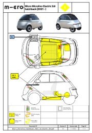
Notes on the vehicle<br />
• Chassis number; In the right-hand footwell<br />
punched into the sheet metal under the carpet<br />
• On the engine: Engine type plate<br />
• Rear tailgate: Tyre pressure sticker<br />
• On the lower edge of the side sill; Marking<br />
for lifting points (on both sides of the sides of<br />
the vehicle)<br />
Battery technology Li Ion NMC / NCA Technology Li Ion NMC / NCA Technology<br />
Reichweite (ca. KM*) 91 177<br />
Ladezeit an Haushaltsteckdose SOC<br />
80% (ca.h)<br />
3,5 3,5<br />
Ladeleistungen OBC (kW) 1,35 2,6<br />
BATTERY & CHARGE SHORT RANGE MEDIUM RANGE<br />
Power (kW) 12,5 12,5<br />
Dimension<br />
max. torque (Nm) 89 89<br />
Overall length<br />
Overall width<br />
Total height<br />
Edge distance<br />
Track width front<br />
Track width rear<br />
Turning circle<br />
2519 mm<br />
1473 mm<br />
1501 mm<br />
1566 mm<br />
1250 mm<br />
930 mm<br />
7400 mm<br />
Power consumption driving mode<br />
according to WMTC (approx.<br />
kWh/100km)<br />
Electricity consumption incl. charging<br />
losses (kWh/100 km)<br />
Gasoline equivalent calculated (approx.l/100<br />
km)<br />
5.93 6.59<br />
13,9 13,9<br />
1,5 1,5<br />
DRIVING PERFORMANCE SHORT RANGE MEDIUM RANGE<br />
Acceleration 0-50 km/h (s) 5 5<br />
Wheels and tyres<br />
- Steel rim 4.5 J x 13H offset 30 with tyres summer or winter 145/70 R13<br />
- Steel rims: 40Nm wheel bolt tightening torque<br />
- Tyre pressure front and rear 1.8 bar<br />
Maximum speed (km/h) 90 90<br />
WEIGHT SHORT RANGE MEDIUM RANGE<br />
Unloaded weight without battery (kg) 435 435<br />
Unloaded weight incl. battery** (kg) 596 613<br />
Permitted total weight (kg) 750 750<br />
Load capacity (kg) *** 154 137<br />
26<br />
* depending on driving style, distance, temperature and number of electrical equipment switched on<br />
** including full equipment for a driver of 75kg<br />
*** payload for passenger and luggage for a driver of 75kg
WARRANTY<br />
The two-year <strong>Microlino</strong> new vehicle warranty without mileage limit applies. The warranty<br />
period begins on the day of the actual handover of the new vehicle to the first customer or on<br />
the day of the first registration, whichever comes first.<br />
The drive battery installed in each case is guaranteed for 6 years or 2500 charging cycles.<br />
The buyer is entitled to the repair of faults and damage caused by these to other parts of the<br />
parts of the vehicle (rectification). The warranty obligation is not affected by change of ownership<br />
of the automobile. The warranty expires if:<br />
• The purchaser does not report a fault immediately and an authorised service partner is<br />
not given the opportunity to rectify the fault.<br />
• The vehicle has been improperly handled or overused, e.g. during competitions, off-road<br />
driving, etc.<br />
• The vehicle has not been repaired or maintained in accordance with the maintenance,<br />
repair guidelines and care of the vehicle (e.g. operating instructions or properly kept<br />
service booklet) or if the defect is due to an - even if only temporary - vehicle overload/<br />
overloading, technical manipulation or operating errors on the part of the driver‘s operating<br />
errors.<br />
• Surface damage occurs which is due to external influences (e.g. stone chips, state ofcare,<br />
environmental influences, etc.).<br />
• The defect that occurs is causally related to the fact that during previous maintenance,<br />
repairs or installations were not carried out using original parts were used.<br />
• The defect that occurs is causally related to the fact that the vehicle has been fully or<br />
partially wrapped.<br />
Natural wear and tear is excluded from the warranty. This applies to all parts of the vehicle,<br />
which are subject to constant wear and tear as part of their normal function (such as z. e.g.<br />
fuses, filters, brake discs, brake pads, shock absorbers, tyres, windscreen wiper blade, lamps,<br />
upholstery, floor coverings and the like).<br />
The same applies to damage to windows after the vehicle has been taken over by the buyer.<br />
Warranty services do not extend the warranty period and do not initiate a new warranty<br />
period. Defects claimed within the warranty period but not remedied are covered by the<br />
warranty until they have been remedied; in the case of this defect, the warranty period is<br />
suspended. However, it ends at the latest three months after the authorised service partner<br />
declares that the defect has been eliminated or that there is no defect.<br />
27
The following are excluded from the warranty (warranty exclusions):<br />
• Replacement of wear parts (e.g. tyres, brake pads and discs, cabin filters, windscreenwipers).<br />
• Elimination of vibrations and noises resulting from the operation of the vehicle operation<br />
of the vehicle.<br />
• Elimination of colour deviations, changes or deformations of the parts due to their normal<br />
ageing.<br />
• Elimination of damage caused by use and consequences of non-compliance with regulations,<br />
of non-compliance with regulations listed in the operating instructions or which have<br />
been neglect duties of care.<br />
• Elimination of damage and consequential damage caused by the use of liquids, substitute<br />
not approved by the manufacturer, spare parts or accessories, lubricants or additives. or<br />
additives not approved by the manufacturer.<br />
• Elimination of damage and consequential damage caused by natural forces (e.g. hail,<br />
flooding, lightning, storms or other atmospheric phenomena), accidental damage (e.g.<br />
fire, water, falling rocks, broken glass, etc.) or other external influences (e.g. war, civil war,<br />
riots, vandalism, theft, rodents, pets, bird droppings, etc.).<br />
IMPORTANT<br />
<strong>Microlino</strong> AG complies with the legal warranty framework and regulations of the countries<br />
in which it carries out its activity. The new car warranty is granted voluntarily by the brand: it<br />
is granted in addition to the existing legal provisions.<br />
It grants the customer, within the limits previously established (in particular territorial, time and<br />
mileage related), the right to free repair or replacement of parts of his vehicle recognized by<br />
the brand as defective, provided that the corresponding work is carried out within the brand’s<br />
network of authorized contractors. An overview of the authorized contractors can be found<br />
on the manufacturer’s website.<br />
The territorial areas refer to the mainland of the delivering country.The performance of warranty<br />
work in overseas territories and on islands will be carried out by case-by-case decisions<br />
of the manufacturer at reasonable distances.<br />
28
INDEX<br />
Bluetooth Speaker 15<br />
Brake Fluid 22<br />
Brakes 13, 21<br />
Central control 10, 11, 12<br />
Charging 5,15, 16, 17, 21, 22, 25<br />
Controls 8, 10, 13, 14, 20, 25<br />
Dashboard 4,10, 12, 13,14, 17, 18, 19<br />
Drive battery 15, 16, 17<br />
Driving Level 4, 20, 22<br />
Driving levels 4, 20, 24<br />
Electric vehicle 4<br />
Emergency release 7,17<br />
Exterior Mirrors 10, 25<br />
Failure controls 19, 20<br />
Flat tyre 24<br />
Fuses 23<br />
Gear selection 20, 21<br />
Handbrake 5, 7, 17, 20, 22<br />
Hazard warning lights 14,19<br />
Heater 4,11<br />
Heating windscreen 11<br />
Horn 13,14<br />
Horn 14<br />
Indicator 10, 13, 14<br />
Indicators 10, 11, 12, 19, 20, 21<br />
Interior lighting 11, 14<br />
Key 7,8,17,18, 22, 24<br />
Lifting Points 24<br />
Lighting 11, 13, 14<br />
Locking system 7,8,9,17<br />
Low beam 13, 19<br />
Maintenance 22, 23, 24, 25<br />
Maintenance 25<br />
Maintenance interval 25<br />
Parking 5, 15, 22, 25<br />
Parking the vehicle 5, 15, 22<br />
Rear window heating 11,12<br />
Regenerative braking 21<br />
Replacing the key battery 24<br />
Safety 4,5,7,15,19<br />
Seat 5,6,9<br />
Seat Belts 5, 6<br />
Seat belts 5,6<br />
Settings 25<br />
Sliding roof 10<br />
Sport mode 4, 10, 21<br />
Starting Switch 18<br />
Storage 17, 18<br />
Symbols 10, 11, 12, 19, 20, 21<br />
Tailgate 7,9,11<br />
Towing 7, 24<br />
Towing Eye 18, 24<br />
Tyre pressure 26<br />
USB connection 15<br />
Vehicle key 7, 8, 17, 18, 19, 22, 24<br />
Ventilation 11,12<br />
Warning messages 4, 19, 20<br />
Warranty 27<br />
Wheel bolt tightening torque 24, 26<br />
Windows 10<br />
Windscreen washer water 22<br />
Windscreen wiper 4,14<br />
12V battery 22, 23, 25<br />
12V disconnector 25<br />
29
30<br />
For more information about the vehicle,<br />
refer to your manual. The language can be<br />
changed on the website.<br />
Watch the instruction video.<br />
© <strong>Microlino</strong> AG 2023.<br />
All rights reserved, including those of sale, exploitation, duplication,<br />
processing, distribution and establishment of proprietary rights, and the<br />
creation of property rights are reserved. The data provided is for product<br />
description purposes only. A statement about a certain or suitability for a<br />
particular purpose can be derived from our information. The information<br />
does not release the user from his or her own tests and trials. It should be<br />
noted that our products are subject to a natural process of wear and tear<br />
and ageing. An example configuration is shown on the cover page.<br />
The vehicle delivered may therefore differ from the illustration.<br />
<strong>Microlino</strong> AG<br />
Bahnhofstrasse 10, 8700 Küsnacht<br />
Switzerland<br />
info @microlino-car.com<br />
www.microlino-car.com<br />
microlino-car<br />
microlino-car