Development of a Cold Gas Propulsion System for the ... - SSL - MIT
Development of a Cold Gas Propulsion System for the ... - SSL - MIT Development of a Cold Gas Propulsion System for the ... - SSL - MIT
4.1.1 Flight Profiles Hopper flight profiles were entered into in the MATLAB model in terms of varying vertical and horizontal thrust. As discussed in section 3.1.3, the vertical thrust requirements throughout a hop of the desired dimensions were fairly well defined. Because the hopper would constantly lose mass during a hop as it expended nitrogen propellant, the vertical thrust levels for each phase of the hop were defined in terms of T/W, with a new vehicle weight calculated at each timestep of the solution based on previous gas usage. It was assumed that all four vertical thrusters would fire together to provide the total vertical thrust needed from the CGSE. There was more variation possible in defining the horizontal thrust for the transit phase of the hop. For all flight profiles, it was assumed that horizontal thrusters would fire in pairs, to accelerate or decelerate the hopper in the direction parallel to its Z axis (see Figure 3-2), with no steering or other rotation. However, the hopper could have short periods of acceleration and deceleration with a longer cruise at relatively low constant velocity, or longer periods of acceleration and deceleration resulting in a shorter cruise at higher velocity. In the limit, the hopper would accelerate horizontally for the entire first half of the transit phase and then decelerate over the second half, with no constant-velocity cruise in between. Several different horizontal acceleration profiles were modeled in order to judge their effect on CGSE design requirements. It should be noted that throughout all phases of the hop, attitude control was known to be necessary but not modeled. Possible sources of disturbances were identified to include gusts of wind (though it was planned to operate the TALARIS hopper indoors if possible to mitigate this), misalignments in the CGSE (i.e. a thruster mounted at a slight angle to its primary direction of force), and torques or lateral forces caused by the EDF weight relief propulsion system. The magnitude of these disturbances was not known at the time the model was written, so it was not possible to make an accurate estimate of the total amount of impulse necessary for attitude control, but it was assumed that it would be much smaller than the impulse required to perform the major planned vehicle maneuvers. Therefore, flight profiles were only considered feasible if the model indicated there was surplus gas available in the tanks at the end of a hop. It was assumed that this additional margin would be used for attitude control during a real hop. 48
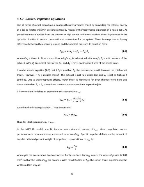
4.1.2 Rocket Propulsion Equations Like all forms of rocket propulsion, a cold gas thruster produces thrust by converting the internal energy of a gas to kinetic energy in an exhaust flow by means of thermodynamic expansion in a nozzle [28]. As propellant mass is ejected from the thruster at high speeds in the exhaust flow, thrust is produced in the opposite direction to ensure conservation of momentum for the system. Thrust is also produced by any difference between the exhaust pressure and the ambient pressure. In equation form:
- Page 1: Development of a Cold Gas Propulsio
- Page 5: Abstract The TALARIS (Terrestrial A
- Page 9 and 10: Table of Contents List of Figures .
- Page 11: 7 Ongoing and Future Work .........
- Page 14 and 15: Figure 6-6. Identification of thrus
- Page 17 and 18: Notation Acronyms and Abbreviations
- Page 19 and 20: N newton Pa pascal psi pounds per s
- Page 21 and 22: 1 Introduction The TALARIS (Terrest
- Page 23 and 24: the idea of hopping was born, and i
- Page 25 and 26: However, as stated before, this doe
- Page 27 and 28: Figure 2-3. Diagram of ACAT lander
- Page 29 and 30: An alternate approach to resolving
- Page 31 and 32: accurate conditions for testing GNC
- Page 33 and 34: Ballistic hops tend to use less pro
- Page 35 and 36: 2.3.2 Comparison of Cold Gas and Mo
- Page 37 and 38: Handling propellant There are sever
- Page 39 and 40: and if the cold gas system was foun
- Page 41 and 42: 3 TALARIS CGSE Design Framework Aft
- Page 43 and 44: Figure 3-1. Scaling of TALARIS terr
- Page 45 and 46: (3) Providing attitude control Ther
- Page 47 and 48: Figure 3-2 also shows the body coor
- Page 49: 4 Modeling and Flow Control Compone
- Page 53 and 54: variables in equation (4-8) deal wi
- Page 55 and 56: equations. Equation (4-10) was then
- Page 57 and 58: that of helium (0.227 MPa = 32.9 ps
- Page 59 and 60: thruster solenoid valve, and chambe
- Page 61 and 62: where
- Page 63 and 64: discussed later in section 6.3.4, t
- Page 65 and 66: The flight profile begins with maxi
- Page 67 and 68: hop, any given valve or regulator o
- Page 69 and 70: esponse time was an important perfo
- Page 71 and 72: directly opens and closes the main
- Page 73 and 74: If 1D isentropic flow is assumed, t
- Page 75 and 76: 5 Single-Stream Component Testing A
- Page 77 and 78: the solenoid valve, and a pressure
- Page 79 and 80: As indicated in Figure 5-3, initial
- Page 81 and 82: Figure 5-5. CGSE high side as const
- Page 83 and 84: Figure 5-7 illustrates several aspe
- Page 85 and 86: 6 Full Eight-Thruster Flight System
- Page 87 and 88: Figure 6-2. TALARIS CGSE assembled
- Page 89 and 90: stream tests revealed that changes
- Page 91 and 92: Figure 6-5. Original CGSE control c
- Page 93 and 94: other constraints. This was difficu
- Page 95 and 96: variables (such as number of thrust
- Page 97 and 98: One solution to this problem would
- Page 99 and 100: One of the characterization tests w
4.1.2 Rocket <strong>Propulsion</strong> Equations<br />
Like all <strong>for</strong>ms <strong>of</strong> rocket propulsion, a cold gas thruster produces thrust by converting <strong>the</strong> internal energy<br />
<strong>of</strong> a gas to kinetic energy in an exhaust flow by means <strong>of</strong> <strong>the</strong>rmodynamic expansion in a nozzle [28]. As<br />
propellant mass is ejected from <strong>the</strong> thruster at high speeds in <strong>the</strong> exhaust flow, thrust is produced in <strong>the</strong><br />
opposite direction to ensure conservation <strong>of</strong> momentum <strong>for</strong> <strong>the</strong> system. Thrust is also produced by any<br />
difference between <strong>the</strong> exhaust pressure and <strong>the</strong> ambient pressure. In equation <strong>for</strong>m:


