You also want an ePaper? Increase the reach of your titles
YUMPU automatically turns print PDFs into web optimized ePapers that Google loves.
www.elcometerndt.com Flaw Detection Gauges<br />
1
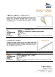
FD700+ & FD700DL+<br />
These small powerful hand-held<br />
flaw detectors combine<br />
state-of-the-art flaw detection<br />
with advanced material<br />
thickness capabilities.<br />
With all the functionality of the top of the range<br />
material thickness gauge, the FD700+ series, when in<br />
flaw detection mode offers a variety of tool kits which<br />
enable fast and accurate flaw detection, ideal for weld<br />
inspection, forgings or composite material testing.<br />
Tool kits include:<br />
� TRIG enabling location of flaws in both surface<br />
distance and depth.<br />
� DAC for the creation of DAC curves which are<br />
used to inform the operator of the size of any<br />
given flaw at any depth.<br />
� AWS function provides automatic defect<br />
sizing in accordance with AWS D1.1 structural<br />
welding code.<br />
� AVG/DGS allows automatic defect sizing using<br />
probe data, storing up to 64 custom setups.<br />
� TCG (time corrected gain) increases gain as<br />
distance increases, in order to achieve an over<br />
all level of sensitivity for the same flaw/reflector<br />
at different distances.<br />
2<br />
www.elcometerndt.com
Flaw Detection Gauges<br />
Advantages<br />
� Exceptional visibility in sunlight (AMOLED)<br />
colour VGA display (320x240 pixels)<br />
� Sizing Toolkits: DAC, AWS, TCG, DGS<br />
� P.R.F. - 8 to 333 Hz, adjustable<br />
� Screen Refresh Rate: Adjustable 60 & 120 Hz<br />
� Detection: Z-Cross, Flank & Peak<br />
� Automatic: probe zero, probe recognition, and<br />
temperature compensation<br />
� Measurement: Variety of modes to address a<br />
number of applications<br />
� Large data storage with multiple formats:<br />
Alpha numeric grid and sequential w/auto<br />
identifier<br />
� Up to 12 hours of battery life<br />
� <strong>Data</strong> management software<br />
www.elcometerndt.com<br />
3
FD700+ & FD700DL+<br />
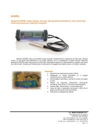
TRIG<br />
TRIG enabling location<br />
of flaws in both surface<br />
distance and depth.<br />
Trigonometric display of<br />
beam path, depth, surface<br />
distance, and curved<br />
surface correction.<br />
Used with angle beam<br />
transducers.<br />
DAC<br />
Distance amplitude<br />
correction for the creation<br />
of DAC curves which are<br />
used to inform the operator<br />
of the size of any given<br />
flaw at any depth.<br />
AWS<br />
The American Weld<br />
Standard function provides<br />
automatic defect sizing in<br />
accordance with AWS D1.1<br />
structural welding code.<br />
TCG<br />
Time corrected gain<br />
increases gain as distance<br />
increases, in order to<br />
achieve an over all level<br />
of sensitivity for the same<br />
flaw/reflector at different<br />
distances.<br />
4<br />
Model & Part Number FD700+ & FD700DL+<br />
Display Mode:<br />
Material thickness digits display<br />
B-Scan cross sectional display<br />
B-Scan with digits display<br />
Scan bar display<br />
Coating thickness display<br />
A-Scan display<br />
Flaw detection modes<br />
www.elcometerndt.com<br />
●<br />
●<br />
●<br />
●<br />
●<br />
+ Rectified, - Rectified, Full Waveform (RF)<br />
TRIG, DAC, AWS, TCG,<br />
Zero Crossing, Flank, Peak<br />
Measurement Mode¹ PE, PETP (Temp Compensation),<br />
EE (ThruPaint), EEV, CT (Coating) & PECT<br />
Measurement Rate (Thickness Mode)<br />
Manual:<br />
Scan mode<br />
Scan bar display<br />
4 readings per second<br />
32 readings per second<br />
6 readings per second<br />
Measuring Range² PE: 0.63 - 30480mm (0.025 - 12,000 inches)<br />
PETP: 0.63 - 30480mm (0.025 - 12,000 inches)<br />
EE: 1.27 - 102mm (0.050 - 4.000 inches)<br />
EEV: 1.27 - 25.4mm (0.050 - 1.000 inches)<br />
CT: 0.01 - 2.54mm (0.0005 - 0.100 inches)<br />
PECT: 0.63 - 30480mm (0.025 - 12,000 inches)<br />
PECT: 0.01 - 2.54mm (0.0005 - 0.100 inches)<br />
Measurement Accuracy² ±0.01mm (±0.001 inches)<br />
Measurement Resolution 0.01mm (0.001 inches)<br />
Velocity Calibration Range 256 - 16,000m/s (0.0100 - 0.6300in/ms)<br />
Additional Features:³<br />
High speed scan mode<br />
Differential mode<br />
Limit alarm mode<br />
B-Scan display speed adjustable display speed<br />
Calibration Setups 6 factory & 64 user-definable setups<br />
transferrable to and from a PC archive<br />
Gates 3 fully adjustable gates:<br />
start, stop, width & threshold<br />
Damping adjustable; impedance matching for<br />
optimising transducer performance<br />
Pulser Type dual 200 volt square wave pulsers with<br />
adjustable pulse width (spike, thin, wide)<br />
and 50 volt cut/boost for greater penetration<br />
Gain manual, automatic gain control (AGC)<br />
with 110dB range with 0.2dB resolution<br />
Timing precision 25MHz TCXO with single shot<br />
100MHz 8bit ultra low power 8 bit digitizer<br />
<strong>Data</strong> Logging<br />
Material Thickness Features<br />
●<br />
●<br />
●<br />
� 8,000 with A/B-scan image & gauge settings<br />
� 210,000 - coating, material, min, max thickness<br />
� sequential and grid logging<br />
� Alpha numeric batch identification<br />
� OBSTRUCT indicates inaccessible locations<br />
Calibration Options single, two point, velocity & material type<br />
Transducer Recognition automatic<br />
V-path / dual path error correction automatic<br />
Probe Zero automatic<br />
¹ PE: Pulse-Echo Mode, EE: Echo-Echo (ThruPaint) Mode;<br />
See page 3 for further information<br />
² Measuring range & accuracy depends on material, surface conditions and<br />
the transducer selected<br />
³ See page 5 for a full explanation of the features
Flaw Detection Mode Features<br />
Automatic<br />
Calibration:<br />
Flaw Detection Features<br />
Longitudinal (straight),<br />
or Shear (angle)<br />
Probe Types: Single Contact, Dual, Delay & Angle<br />
Material Velocity Table: Contains longitudinal and shear<br />
velocities for a variety of material types<br />
TRIG Trigonometric display of beam path,<br />
depth, surface distance, and curved surface<br />
correction. Used with angle beam transducers<br />
DAC Up to 8 points may be entered and used to digitally<br />
draw a DAC curve. Reference -2, -6, -10, (-6/-12),<br />
(-6/-14), (-2/-6/-10) dB. Amplitude displayed in<br />
%DAC, dB, or %FSH<br />
AWS Automatic defect sizing in accordance with AWS<br />
D1.1 structural welding code.<br />
AVG/DGS Automatic defect sizing using probe<br />
data. Stores up to 64 custom setups<br />
TCG Time corrected gain. 50 dB dynamic range, 20 dB<br />
per microsecond, up to 8 points for curve definition<br />
Detection Modes Zero Crossing, Flank and Peak<br />
Display Freeze Hold current waveform on screen<br />
Peak Memory Captures peak signal amplitude.<br />
P.R.F 8 to 333Hz in selectable steps (8, 16, 32, 66, 125,<br />
250, 333Hz)<br />
Pulse Width 40 to 400 ns. Selectable step<br />
options 40, 80 & 400 ns (labeled spike, thin &<br />
wide)<br />
Frequency Bands FD700+ & FD700DL+: Broadband 1.8 - 19 MHz<br />
(-3dB). FD700DL+: Three<br />
narrow bands at 2MHz, 5MHz, 10MHz<br />
Horizontal Linearity +/- 0.4% FSW<br />
Vertical Linearity +/- 1% FSH<br />
Amplifier Linearity +/- 1 dB<br />
Amplitude Measurement 0 to 100% FSH, with 1% resolution<br />
Delay 0 - 999in (25,375mm) at steel velocity<br />
Display 1/4 VGA AMOLED colour display<br />
57.6 x 43.2mm (2.27 x 1.78inches)<br />
viewable area<br />
Display Refresh Rate 120Hz<br />
Units (selectable) mm or inches<br />
Backlight adjustable brightness<br />
Repeatability / Stability Indicator ●<br />
Battery Type 3 x AA alkaline<br />
Battery Life<br />
(approximate)<br />
12 hours<br />
Low Battery Indicator ●<br />
Battery Save Mode auto<br />
Operating Temperature -10 to 60ºC (14 to 140ºF)<br />
Size (w x h x d) 63.5 x 165.0 x 31.5mm<br />
(2.5 x 6.5 x 1.24 inches)<br />
Weight (including batteries) 397g (14oz)<br />
Case Design Aluminium case design with gasket sealed end<br />
caps, waterproof membrane keypad<br />
Transducer Connector Type LEMO<br />
RS232 Interface Bi-directional<br />
Packing List Elcometer NDT FD700+ or FD700DL+ gauge,<br />
couplant, carry case, user manual, test certificate,<br />
3 x AA batteries, software, transfer cable<br />
www.elcometerndt.com<br />
Specifications<br />
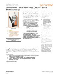
Zero Crossing<br />
The gate detects the<br />
flank of the pulse, but the<br />
measurement is taken at<br />
the next crossing of the<br />
x axis. This is the most<br />
common type of detect in<br />
ultrasonic measurement.<br />
Flank<br />
The gate is triggered by<br />
the flank (or side) of the<br />
pulse on the graph and the<br />
measurement taken at this<br />
exact point.<br />
Peak<br />
The gate is triggered by the<br />
intersection with the A-scan<br />
pulse and the detection is<br />
taken from the next peak<br />
in the signal (when it stops<br />
rising and starts falling).<br />
5
ENGLAND<br />
Elcometer Limited<br />
Manchester M43 6BU<br />
Tel: +44 (0)161 371 6000<br />
Fax: +44 (0)161 371 6010<br />
e-mail: sales@elcometer.com<br />
FRANCE<br />
Elcometer Sarl<br />
45430 BOU<br />
Tel: +33 (0)2 38 86 33 44<br />
Fax: +33 (0)2 38 91 37 66<br />
e-mail: fr_info@elcometer.com<br />
6<br />
Corrosion Gauges<br />
Velocity Gauges<br />
USA<br />
Elcometer Inc<br />
Rochester Hills Michigan 48309<br />
Tel: +1 248 650 0500<br />
Toll Free: 800 521 0635<br />
Fax: +1 248 650 0501<br />
e-mail: inc@elcometer.com<br />
GERMANY<br />
Elcometer Instruments GmbH<br />
D-73431 Aalen<br />
Tel: +49(0)7361 52806 0<br />
Fax: +49(0)7361 52806 77<br />
e-mail: de_info@elcometer.de<br />
Precision Gauges<br />
Sonic Gauges<br />
www.elcometerndt.com<br />
REPUBLIC OF SINGAPORE<br />
Elcometer (Asia) Pte Ltd<br />
Singapore 589472,<br />
Tel: +65 6462 2822<br />
Fax: +65 6462 2860<br />
e-mail: asia@elcometer.com<br />
BELGIUM<br />
Elcometer SA<br />
B-4681 Hermalle /s Argenteau<br />
Tel: +32 (0)4 379 96 10<br />
Fax: +32 (0)4 374 06 03<br />
e-mail: be_info@elcometer.com<br />
www.elcometerndt.com<br />
Flaw Detection<br />
Bolt Gauges<br />
JAPAN<br />
Elcometer KK<br />
Minato-ku, Tokyo<br />
Tel: +81 (0)3-4530-9714<br />
Fax: +81 (0)3-4530-9713<br />
e-mail: jp_info@elcometer.com<br />
THE NETHERLANDS<br />
Elcometer NL<br />
3584 BH Utrecht<br />
Tel: +31 (0)30 210.7005<br />
Fax: +31 (0)30 210.6666<br />
email: nl_info@elcometer.com<br />
© Elcometer Limited, 2011. SLI0047 Issue 1<br />
All rights reserved. No part of this document may be reproduced, transmitted, stored (in a retrieval system or otherwise), or translated into any language, in any form, or by any means, without the prior written<br />
permission of Elcometer Limited.<br />
Elcometer is a registered trademark of Elcometer Limited. ThruPaint is a trademark of Elcometer Limited. All other trademarks are acknowledged. Due to our policy of continuous improvement,<br />
Elcometer Limited reserves the right to change specifications without notice.